

Page 1

Plasma Monitor
User’s Guide
Changing Entertainment. Again.
PHD42600
Page 2

Important Information
CAUTION
RISK OF ELECTRIC
SHOCK DO NOT OPEN
Caution: To reduce the risk of electric shock, do not
remove cover (or back). No user serviceable parts
inside. Refer servicing to qualified service personnel.
WARNING
To reduce the risk of fire or electric
shock, do not expose this product
to rain or moisture.
The apparatus should not be
exposed to dripping or splashing
and no objects filled with liquids,
such as vases, should be placed on
the apparatus.
Refer to the identification/rating label located on the back panel of your
product for its proper operating voltage.
FCC Regulations state that unauthorized changes or modifications to this
equipment may void the user’s authority to operate it.
Caution: Using video games or any external accessory with fixed
images for extended periods of time can cause them to be permanently
imprinted on the picture tube (or projection TV picture tubes, or
plasma panel). ALSO, some network/program logos, phone numbers,
etc. may cause similar damage. This damage is not covered by your
warranty.
Cable TV Installer: This reminder is provided to call your attention to Article
820-40 of the National Electrical Code (Section 54 of the Canadian Electrical
Code, Part 1) which provides guidelines for proper grounding and, in
particular, specifies that the cable ground shall be connected to the grounding
system of the building as close to the point of cable entry as practical.
This symbol indicates important instructions
accompanying the product.
This symbol indicates "dangerous voltage"
inside the product that presents a risk of
electric shock or personal injury.
Product Registration
Please fill out the product registration card (packed separately) and return it immediately. For U.S. customers: Your RCA
Consumer Electronics product may also be registered at www.rca.com/productregistration. Registering this product
allows us to contact you if needed.
Product Information
Keep your sales receipt to obtain warranty parts and service and for proof of purchase. Attach it here and record the
serial and model numbers. These numbers are located on the product.
Model No. ____________________ Serial No. __________________ Purchase Date: ______________
Dealer/Address/Phone: _________________________________________________________________
Page 3

Table of Contents
Chapter 1: Connections & Setup
Things to Consider Before You Connect ........................................................................................ 3
Protect Against Power Surges.................................................................................................. 3
Protect Components from Overheating.................................................................................. 3
Important Stand and Base Safety Information ....................................................................... 3
Position Cables Properly to Avoid Audio Interference........................................................... 3
Use Indirect Light...................................................................................................................... 3
Connection Illustrations ........................................................................................................... 3
Receiving Channels ................................................................................................................... 3
Check Supplied Parts ................................................................................................................ 3
Installation of the Monitor ............................................................................................................. 4
Installation using a stand or wall mount bracket................................................................... 4
Mounting or Removing the Table Stand ................................................................................. 4
The Front of Your Monitor .............................................................................................................. 5
Explanation of Jacks ........................................................................................................................ 6
Choose Your Connection ................................................................................................................. 8
Connection to audio/video components ................................................................................. 8
Connection to a personal computer...................................................................................... 10
Connection to an external monitor....................................................................................... 11
Connecting speakers .............................................................................................................. 11
Plug in the Monitor ....................................................................................................................... 12
Put batteries in the remote........................................................................................................... 12
Turn on the Monitor ...................................................................................................................... 12
Set up Your Monitor ...................................................................................................................... 12
Choose the Menu Language .................................................................................................. 12
Chapter 2: Using the Remote Control
Button Descriptions for Monitor Mode ....................................................................................... 13
Button Descriptions for Other Components................................................................................ 14
Using the INPUT Button ......................................................................................................... 15
Programming the Remote to Operate Other Components ........................................................ 15
Find Out If You Need to Program the Remote ..................................................................... 15
Programming the Remote ..................................................................................................... 15
How to Use the Remote After You’ve Programmed It ......................................................... 16
Remote Control Codes .................................................................................................................. 17
Chapter 3: Using the Monitor’s Features
About the Status Display .............................................................................................................. 19
Why You Should Use the Autotuning Feature ............................................................................ 19
How to Set Up the Autotuning Feature................................................................................ 19
Zoom Modes .................................................................................................................................. 20
Remote Control Buttons for Zoom Modes............................................................................ 21
Auto Set ......................................................................................................................................... 21
Chapter 4: Using the Menu System
Menus, On-screen Help and Control Panels ................................................................................ 22
Exiting a menu ........................................................................................................................ 22
Controls ................................................................................................................................... 22
Picture Menu .................................................................................................................................. 23
Picture Menu (when using DVI or RGB inputs) ..................................................................... 24
Picture Geometry .................................................................................................................... 24
Advanced Settings .................................................................................................................. 25
Sound Menu................................................................................................................................... 26
Preferences Menu .......................................................................................................................... 26
(continued on next page)
1
Page 4

Table of Contents
Chapter 5: Other Information
Troubleshooting ............................................................................................................................. 27
Care and Cleaning ......................................................................................................................... 28
Specifications ................................................................................................................................. 29
FCC Declaration of Conformity and Industry Canada Information............................................ 33
Limited Warranty........................................................................................................................... 34
Accessory Information .................................................................................................................. 36
How to Order .......................................................................................................................... 36
2
Page 5

Chapter 1: Connections and Setup
Things to Consider Before You Connect
Protect Against Power Surges
• Connect all components before you plug any of their power cords into the wall outlet or power strip. NEVER plug your
monitor into an outlet that is controlled by a wall switch.
•Turn off the monitor and/or component(s) before you connect or disconnect any cables.
• Make sure all antennas and cables are properly grounded. Refer to the Important Safeguards sheet packed with your
monitor.
Protect Components from Overheating
• Don’t block ventilation holes on any of the components. Arrange the components so that air can circulate freely.
• Don’t stack components.
•When you place components in a stand, make sure you allow adequate ventilation.
• If you connect an audio receiver or amplifier, place it on the top shelf so the heated air from it won’t flow around
other components.
Important Stand and Base Safety Information
If a stand or base is used insure that it is of adequate size and strength to prevent the TV from being accidentally tipped
over, pushed off, or pulled off. This could cause personal injury and/or damage the TV. Refer to the Important Safety
Instructions packed separately.
Position Cables Properly to Avoid Audio Interference
• Insert each cable firmly into the designated jack.
Use Indirect Light
Don’t place the monitor where sunlight or room lighting will be directed toward the screen. Use soft or indirect lighting.
Connection Illustrations
The components used in the connection illustrations are for representation only.
Receiving Channels
In order for your Plasma Monitor to display television programming, you must connect a component than can receive
programming (e.g. satellite receiver, HD receiver, or cable box).
ON•OFF
VCR1
MONITOR
SAT•CABLE
AUX
VCR2
Check Supplied Parts
Check that the following parts were
packed with your product.
DVD
MUTE
L
O
V
A
AUTO SET
GUIDE
MENU
1
4
7
INPUT
RECORD
REPEAT
u n i v e r s a l
2
5
8
0
AUDIO
H
+
C
C
–
H
OK
Z
O
O
M
PLAY FORWARDREVERSE
STOP PAUSE
ANGLE OPEN
DVD
CINEMA
V
O
L
GO BACK
INFO
CLEAR
3
6
9
ANTENNA
2 AA batteries
Power cord
Remote Control
Chapter 1 3
Graphics contained within this publication are for representation only.
Page 6

Connections and Setup
Installation of the Monitor
Installation using a stand or wall mount bracket
• Please be sure to request installation or mounting of this unit or the installation bracket by the dealer where
purchased.
•When installing, be sure to use the bolts provided with the stand or installation bracket.
• For details concerning installation, please refer to the instruction manual provided with the stand or installation
bracket.
Installation using accessories other than the stand or installation bracket (sold separately)
•When possible, please install using parts and accessories manufactured by Thomson. Thomson will not be held
responsible for accident or damage caused by the use of parts and accessories manufactured by other companies.
• For custom installation, please consult the dealer where the unit was purchased.
Note for U.S. customers: If you prefer, we can provide you with the name of an Authorized Service
Representative who will visit your home for a fee to install your electronic entertainment system and to instruct you
in its operation. For details about this service, call 1-888-206-3359.
For additional assistance while using your RCA product, please visit www.rca.com/customersupport.
CAUTIONS
To avoid malfunction, overheating of this unit, and possible fire hazard, make sure that the vents on the main unit
are not blocked when installing. Also, as hot air is expelled from the air vents, be careful of dust build up on rear
surface wall, etc.
This monitor unit is very heavy and has little front-to-back depth, making it very unstable when stood on edge. The
monitor should either be attached to the table stand or mounted on the wall. No other mounting method is
recommended. As a result, two or more persons should cooperate when unpacking, moving, or installing the
monitor.
This unit incorporates a thin design. To ensure safety if vibrated or shaken, please be sure to take measures to
prevent the unit from tipping over.
Mounting or Removing the Table Stand
To mount the monitor to the stand:
1. Lift the plasma monitor and insert the 4
mounting posts on the back of the unit
into the mounting holes on the table
stand.
2. Make sure all the posts are fully inserted,
then let the monitor slide down into the
smaller notches until the posts fit firmly
into place.
3. Insert the screws into the holes on the
back of the stand (as shown) and tighten
them into place.
To remove the monitor from the stand:
Remove the screws, and follow the above
steps in reverse order.
Stand holes for
the monitor’s
mounting posts
4 Chapter 1
Graphics contained within this publication are for representation only.
Page 7

Connections and Setup
INPUT
POWER /
MENU
– VOLUME +
ZOOM
The Front of Your Monitor
If you can’t locate your remote, you can use the front panel of your monitor to operate many of the monitor’s features.
MENU Brings up the Main menu. When the menu system is displayed, pressing MENU selects highlighted items.
VOL
Decreases the volume. In the menu system, it acts like the left arrow button on the remote (moves highlight
left).
VOL
Increases the volume. In the menu system, it acts like the right arrow button on the remote (moves highlight
right).
INPUT Toggles through the available Video Input Channels. In the menu system, it acts like the up arrow button on
the remote (moves highlight up).
ZOOM Toggles through the zoom modes. In the menu system, it acts like the down arrow button on the remote
(moves highlight down).
POWER Turns the monitor on and off. The indicator next to the button lights when monitor is on.
Chapter 1 5
Graphics contained within this publication are for representation only.
Page 8

Connections and Setup
Explanation of Jacks
This section describes the jacks and cables you might use to make connections. There are
several ways to connect components to your monitor.
Different jacks and cables provide a different level of performance. It’s important to remember
the different degrees of picture improvement for comparison. The component jacks (Y, Pb, Pr)
are considered excellent; and S-Video and composite jacks are considered very good.
Note: The illustration below shows how your monitor’s jacks are labeled and where they
are located. The jacks might vary slightly depending on your model.
SUBWOOFER
VID 1
VIDEO
S-VIDEO
R
AUDIO
L
The jack panel is found on the back of the monitor at the bottom part of the raised area.
VIDEO
S-VIDEO
VID 2
R
AUDIO
L
Y
Y
COMPONENT 1
P
B
P
R
P
R
P
B
COMPONENT 2
R
R
– AUDIO –
– AUDIO –
L
L
Back Panel
VID1 and VID2
• S-VIDEO In The S-Video (separate video) jack provides better picture quality than the
regular video jacks because the color (chrominance, also called chroma) part of the signal
is separated from the black and white (luminance) part of the picture.
If a component you’re connecting to your monitor (like a DVD player) has an S-VIDEO
jack and composite video, connect the DVD player to the monitor with an S-Video cable
(not provided) for better quality picture.
AUDIO OUT
L
R
Note: Remember to connect the left and right audio cables to the Audio In jacks because
the S-Video cable carries only the picture signal, not the sound.
• AUDIO In L Provides left audio connection. The left audio connector is usually white.
• AUDIO In R Provides right audio connection. The right audio connector is usually red.
Note: If your component has only one output for audio (mono), connect it to the left
(white) audio jack on the monitor and don’t connect the right (red) audio part of the
cable.
• VIDEO In Provides composite video connection. The video connector is usually yellow.
• SUBWOOFER Provides a connection for your subwoofer for improved bass effects.
6 Chapter 1
Graphics contained within this publication are for representation only.
Page 9

Speaker
jacks
Connections and Setup
Back of the monitor
Raised area (jack panel is
on the bottom)
COMPONENT 1 / COMPONENT2
• YPbPr For connection of components that have component output jacks (Y, Pb, Pr) such
as a personal computer, HD receiver, or DVD player.
The YPbPr jack provides excellent picture quality because the video is separated into three
signals.
• AUDIO In Use to obtain sound when a component is connected to the COMPONENT 1
or 2 jacks.
AUDIO OUT
• AUDIO OUT Use to output the audio of the selected source component connected to this
unit to an AV amplifier or similar component.
SPEAKERS
• For connection of external speakers.
DVI / RGB
• DVI IN For connection of components that have DVI output jacks, such as an HD
receiver.
• Audio In (L and R) Use to obtain sound when a component is connected to the DVI IN
jacks.
• RGB IN / OUT For connection of components that have RGB output or input jacks, such
as a personal computer, HD receiver, or DVD player.
• Audio In (L and R) Use to obtain sound when a component is connected to the RGB IN
jacks.
Chapter 1 7
Graphics contained within this publication are for representation only.
Page 10

Connections and Setup
Choose Your Connection
There are several ways to connect your plasma monitor, depending on the components you
want to connect and the quality of the signal you want to achieve. The following are general
connection examples. Choose the connection which is best for you.
Note: If you prefer, we can provide you with the name of an Authorized Service
Representative who will visit your home for a fee to install your electronic entertainment
system and to instruct you in its operation. For details about this service, call 1-888-206-
3359. For additional assistance while using your RCA product, please visit www.rca.com/
customersupport.
Connection to audio/video components
Using the VID1 and VID2 jacks
Connect a component, such as a VCR, DVD player or satellite receiver, to the monitor using the
VID1 or VID2 jacks. Connect an S-Video cable to the S-VIDEO In jack and to the S-Video Out
jack on the component. Then connect audio cables to the Audio In L and R jacks on the back
of the monitor and to the Audio Output jacks on the component.
Notes:
• If S-Video and composite video are connected at the same time, S-Video takes priority.
• If the component you are connecting only has a video jack, connect the component to
the monitor’s VID1 VIDEO jack using a standard video cable.
VIDEO
S-VIDEO
VID 1
R
AUDIO
L
AV component
8 Chapter 1
Graphics contained within this publication are for representation only.
Page 11

Connections and Setup
ˇ˝ˇ˝ˇ˝ˇ˝ ˇ˝ˇ˝
ˇ˝ˇ˝ˇ˝ˇ˝ˇ˝ ˇ˝ˇ˝ˇ˝ˇ˝ ˇ˝ˇ˝ˇ˝ˇ˝ˇ˝ ˇ˝ˇ˝ˇ˝ˇ˝ˇ˝
Using the Component Video jacks (Y, Pb, Pr)
Connect a component, such as a DVD player or digital cable box, to the monitor using the Y,
Pb, Pr jacks. Connect a component video cable to the Y, Pb, Pr jacks on the back of the
monitor and to the component video jacks (Y, Pb, Pr) on the component. Then connect the
COMPONENT1 AUDIO In (L and R) jacks on the monitor to the Audio Out jacks on the back
of the component using audio cables.
COMPONENT 1
P
B
P
Y
R
L
R
AV component
Using the DVI IN jack
Connect a component using DVI, such as an HD receiver, using the DVI IN jack. Connect one
end of the DVI cable (not supplied) to the DVI Out jack on the back on the component and
the other end to the DVI IN jack on the back of the monitor. Then connect the Audio In jacks
(L and R) next to the DVI IN jack on the monitor to the Audio Out jacks on the back of your
component.
DVI IN
R
L
HD receiver (RCA Scenium ATSC21, for example)
Chapter 1 9
Graphics contained within this publication are for representation only.
Page 12
Connections and Setup
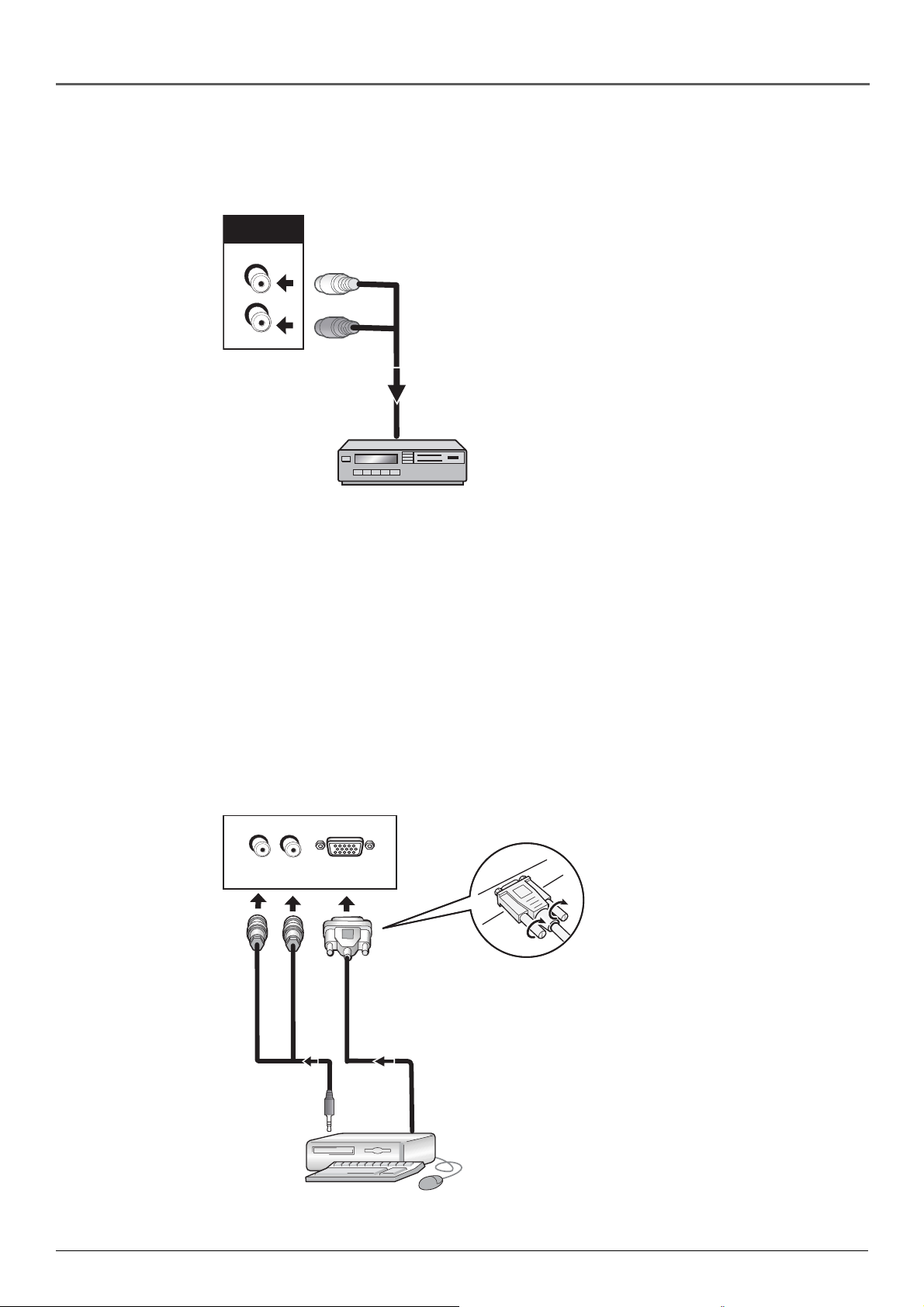
Using the AUDIO OUT jacks
Connect your audio receiver to the monitor using the AUDIO OUT jacks. Connect the Audio
OUT jacks (L and R) on the monitor to the Audio In jacks on the back of your receiver.
AUDIO OUT
L
R
Audio receiver
Connection to a personal computer
Using the RGB IN jack
Connect your computer to the RGB IN jack. Connect one end of a 15-pin monitor cable to the
computer and the other end to the RGB IN jack on the back of the monitor. For sound, you can
connect the Audio In jacks (L and R) next to the RGB IN jack on the monitor to the Audio Out
jack (usually a stereo headphone jack) on the back of your computer using a stereo mini to
RCA plugs cable (not supplied).
R
L
RGB IN
Computer
10 Chapter 1
Graphics contained within this publication are for representation only.
Page 13

Connections and Setup
Connection to an external monitor
This monitor is able to output video signal to an external monitor or other component from the
RGB OUT jack. Connect one end of a 15-pin monitor cable to the external monitor or
component and the other end to the RGB OUT jack on the back of the monitor. Then connect
the Audio OUT jacks (L and R) on the monitor to the Audio In jacks on the back of your
external monitor.
Note: A video signal will not be ouput from the RGB OUT jack when the main power of
this unit is off or in standby.
RGB OUT
To an external monitor
Connecting speakers
Before making connections, be sure to check that the audio component’s power and the unit’s
main power is off. Speaker cords, 1 for each speaker, are needed for connection. Twist the
stripped ends of speaker cord about 2/3 inch (15 mm). Press down on the tab to open the
terminal and insert the wire. Let go to close the tab.
10 mm
Twist exposed wire
strands together.
Push tab to the open
position, and insert the
wire. Then, let go of the
tab to secure the wire
in place.
Note: When making speaker connections, be sure to match the polarities (+ and –) of the
speaker terminals on this unit and the corresponding terminals on the speakers. If the
polarity is reversed, the sound will be unnatural and lack bass.
Chapter 1 11
Graphics contained within this publication are for representation only.
Page 14

Connections and Setup
Plug in the Monitor
Plug the flat end of the cable into the power jack on the back of the
monitor. Then plug the end of the power cord into an appropriate
wall outlet. Be sure to insert the plug completely. Do not plug into an
outlet controlled by a light switch.
Put batteries in the remote
• Remove the battery compartment cover from the back of the
• Insert 2 fresh “AA” batteries. Make sure the polarities (+ and -) are
• Replace the cover.
Turn on the Monitor
remote by pushing down on and sliding off the cover.
aligned correctly.
The back of the monitor
Main power button
1. Push in the main power button on the back of the monitor
(located on the lower-left side).
2. Press MONITOR on the remote, or press POWER on the monitor’s
front panel.
Note: Pressing the MONITOR button turns on the monitor and
puts the remote into monitor mode. “Monitor mode” means
that the buttons on the remote control operate the monitor’s
functions.
Set up Your Monitor
The first thing you need to do after turning on your plasma monitor is
to tune it to the Video Input Channel which corresponds to how it is
connected to the video source signal from the HD receiver, satellite
receiver, or cable box. Make sure the remote is in the monitor mode
by pressing the MONITOR button, then press the INPUT button
repeatedly until the signal appears for the input you have connected.
Remember, the monitor is dependent on an external source for
programming (HD receiver, cable box, etc); it can’t receive channels
on its own.
Choose the Menu Language
If want to change the language of the on-screen displays, follow the
steps below. The default language is English.
1. Press the MENU button on the remote control (the MAIN MENU
appears).
2. Press the down arrow button to highlight Preferences, then press
OK (the Preferences menu appears with Language highlighted).
3. The default language is English. To select French or Spanish, press
the right arrow button.
12 Chapter 1
Graphics contained within this publication are for representation only.
Page 15

Chapter 2: Using the Remote Control
VCR
DVD
MUTE
AUTO SET
GUIDE
MENU
1
4
7
INPUT
RECORD
1
L
O
V
A
Indicator
ON•OFF
AUX
VCR
2
H
+
C
C
H
OK
Z
O
O
M
2
5
8
0
PLAY FORWARDREVERSE
STOP PAUSE
–
MONITOR
SAT•CABLE
CINEMA
V
O
L
GO BACK
INFO
CLEAR
3
6
9
ANTENNA
Button Descriptions for Monitor Mode
In addition to operating your Plasma Monitor, the remote that came
with it can operate your other components. However, this page only
describes the buttons on the remote that you will use with your
monitor.
For descriptions of remote control buttons to be used with your other
components, go to the next page.
In alphabetcial order
(0-9) Number buttons Access the Video Input Channels in the follow
order: 1– Vid1, 2–Vid2, 3–CMP1, 4–CMP2, 5–RGB, 6–DVI.
Arrow buttons Use the arrows to navigate through the menu screens
and make adjustments. When no on-screen menus are displayed, use
the left and right arrow buttons to toggle to the next and previous
zoom modes.
AUTO SET Automatically reverts the picture preset settings to the ones
you chose for the current selected video input.
Backlight ( ) Lights up some of the remote buttons in the dark.
CH +/- Tunes the monitor to the next or previous input. If the
monitor is off, pressing one of these buttons turns on the monitor to
the last used input.
CINEMA Changes the zoom mode to Cinerama no matter which zoom
mode is selected.
CLEAR Clears on-screen displays and returns you to normal viewing.
GO BACK Changes the video input to the last one used.
ANGLE OPEN
AUDIO
REPEAT
DVD
u n i v e r s a l
Note: This remote operates most RCA,
GE, and Proscan products.
Tip
To turn off the RCA, GE, and Proscan
components that are connected to the TV, press
ON•OFF twice within two seconds.
This feature only works with most RCA, GE, and
Proscan products.
INFO Brings up the status display.
INPUT Changes the Video Input Channel. Press the INPUT button
repeatedly until the input channel for the component you have
connected is displayed.
MENU Brings up the on-screen menu.
MONITOR Turns the monitor on and puts the remote in Monitor
mode so the remote operates the monitor.
MUTE Reduces sound to an inaudible level.
OK/ZOOM When menus are on the screen, selects the highlighted
choice. When there are no on-screen menus displayed, press OK/
ZOOM to toggle the available zoom modes.
ON•OFF Turns the monitor off.
VOL< and > buttons Adjust the volume.
Chapter 2 13
Graphics contained within this publication are for representation only.
Page 16

Using the Remote Control
Button Descriptions for Other Components
This remote operates most brands of other components (VCRs, DVD players, satellite receivers,
etc). The following list (in alphabetical order) provides basic information about how these
buttons will operate in these modes.
(0-9) Number buttons Enter channel numbers for a compatible component.
ANGLE Accesses various camera angles when using a compatible RCA, GE, or Proscan DVD
player (if available on the DVD disc).
ANTENNA In VCR mode, functions as the TV/VCR button for compatible VCRs. In satellite
receiver mode, functions as the TV/receiver button.
AUDIO In DVD mode, brings up the Audio language info display on a compatible RCA, GE,
or Proscan DVD player.
AUX (auxiliary) You can program this button to control any one of the following: a cable box;
audio components; a laserdisc player; a VCR; or a satellite receiver; a DVD player; or a DVD/
VCR combo. Press this button to operate the component you’ve programmed to work with the
AUX button.
CH+/CH– buttons Change channels on a compatible component. In DVD mode, changes
next or previous chapters or tracks on a compatible RCA, GE, or Proscan DVD player.
DVD Turns on a compatible RCA, GE, or Proscan DVD player and sets the remote to control
the DVD player. Also used with the ON•OFF button to turn on other compatible DVD players.
FORWARD Fast forwards a tape or searches forward on a DVD disc on a compatible VCR or
DVD player.
GO BACK Returns you to the previous channel on a compatible component.
GUIDE Brings up the on-screen program guide on a compatible component.
ON•OFF Toggles power on and off for the components that you have programmed. For
example, if you are in VCR mode, turns VCR on and off.
OPEN Opens and closes the DVD disc tray on a compatible DVD player.
PAUSE Pauses playback or recording on a compatible VCR. Pauses a DVD disc on a DVD
player.
PLAY Plays a tape or DVD disc on a compatible VCR or DVD player.
RECORD Starts recording on a compatible VCR.
REPEAT Brings up the Repeat info display on a compatible RCA, GE, or Proscan DVD player.
You can repeat part or all of a title, chapter, or track.
REVERSE Rewinds a tape or searches backward on a DVD disc on a compatible VCR or DVD
player.
SAT•CABLE Turns on a compatible RCA, GE, or Proscan satellite receiver, puts the remote in
satellite receiver or cable box mode, and can also be programmed to operate some compatible
satellite receivers or cable boxes.
STOP Stops the current function (play, record, reverse, etc.) on a compatible VCR or DVD
player.
VCR1 and VCR2 buttons Turn on a compatible RCA, GE, or Proscan VCR and set the remote
to control the VCR. Also used with the ON•OFF button to turn on other compatible VCRs.
14 Chapter 2
Graphics contained within this publication are for representation only.
Page 17

Using the Remote Control
Using the INPUT Button
Use the INPUT button to scroll through the available video input channels and view
components you have connected to the monitor.
1. Make sure the component you want to view is turned ON.
2. Press INPUT to tune to the video input channel that corresponds to the jack on the
monitor you used to connect the component.
3. To return to the previous channel, continue pressing INPUT.
Component
buttons
REVERSE
and PLAY
buttons
VCR1
VCR2
DVD
MUTE
L
O
V
A
AUTO SET
GUIDE
MENU
2
1
4
5
7
8
INPUT
0
RECORD
AUDIO
REPEAT
u n i v e r s a l
ON•OFF
AUX
H
+
C
C
–
H
OK
Z
O
O
M
3
6
9
ANTENNA
PLAY FORWARDREVERSE
STOP PAUSE
ANGLE OPEN
DVD
MONITOR
SAT•CABLE
CINEMA
V
O
L
GO BACK
INFO
CLEAR
ON•OFF
button
CLEAR
button
STOP
button
Programming the Remote to Operate Other Components
The universal remote can be programmed to operate most brands of
remote controllable components. The remote is already programmed
to operate most RCA, GE, and Proscan components.
Note: The MONITOR button can’t be programmed on this
remote.
Find Out If You Need to Program the Remote
To determine whether the universal remote needs to be programmed
for your component, turn the component ON. For example, to
program the remote for a VCR, turn on the VCR. Point the remote at
the VCR, and press the VCR1 button. Then press ON•OFF or CH +
(channel up) or CH – (channel down) to see if the VCR responds to
the remote commands. If the component does not respond, the remote
needs to be programmed.
Programming the Remote
There are two ways to program the remote control:
You’ll use these buttons when programming
the remote.
Important: The remote may not be
compatible will all models of all brands
of components. It may also not operate
all functions of the remote that came
with your component.
• automatic code search
• direct entry
Using Automatic Code Search
The following instructions can be used to program the remote to
operate each of your components. If you want to stop the automatic
code search without programming any of your components, press
CLEAR until the indicator on the remote turns off.
1. Turn on the component you want to operate (VCR, DVD player,
etc.)
2. Press and hold the component button you want to program (VCR
or DVD, etc.). While holding the component button, press and
hold ON•OFF until the indicator on the remote turns on, then
release both buttons.
Note: You can also use Automatic Code Search to program the
AUX button for audio components.
3. Point the remote at the component. Press and release PLAY, then
wait 5 seconds or until the indicator on the remote stops flashing.
continued on next page
Chapter 2 15
Graphics contained within this publication are for representation only.
Page 18

Using the Remote Control
At this point the remote is searching for the correct code to program. If, after 5 seconds, the
component you want to operate does not turn off, press PLAY again to tell the remote to
search the next set of codes.
Continue pressing PLAY until the component turns off or you have searched through all of
the codes. There are 20 total sets of codes. If the component does not turn off after
pressing PLAY 20 times, then the remote can’t be programmed to operate that component.
Note: To cancel Code Search, press CLEAR at any time.
If the component you want to operate does turn off:
1. Press and release REVERSE, then wait 2 seconds. Repeat this step until the device turns
back ON.
2. To finish, press and hold STOP until the indicator on the remote turns off.
Using Direct Entry
1. Turn on the component to be programmed.
2. Look up the brand and code number(s) for the component on the code list in this section.
3. Press and hold the component button you want to program on the remote.
4. Enter the code from the remote control code list on the following pages. If the indicator
flashes, you have either entered an invalid code or the button isn’t programmable.
5. Release the component button.
6. Point the remote at the component. Press ON•OFF to see if the component responds to the
command. If it doesn’t, try pressing the component button and then ON•OFF again.
• If you get no response, repeat these steps using the next code listed for your brand, until
the component responds to the remote commands.
• If you try all the codes for your component brand and none work, try the automatic code
search method. If automatic code search doesn’t find the code, the remote is not
compatible with your component.
How to Use the Remote After You’ve Programmed It
Because this universal remote can operate several different components it uses operational
modes triggered by the component buttons. For example, if you want the remote to operate the
monitor, you would press the MONITOR button to put the remote into Monitor mode before
you could operate the unit.
1. Press the appropriate component button (DVD, MONITOR, VCR1, etc.) to set the remote to
operate the component.
2. Press ON•OFF to turn the component ON or OFF.
3. Use the remote buttons that apply to that component.
Notes:
• The remote may not be compatible with all brands and models of components. It also
may not operate all functions of the remote that came with your component.
• If you keep pressing buttons and nothing happens, the remote is probably in the
wrong mode. You must press the component button that matches the component
you want to operate (i.e., if you want to operate the VCR, press VCR1 on the remote
control to put the remote in VCR mode.)
16 Chapter 2
Graphics contained within this publication are for representation only.
Page 19

VCR
Using the Remote Control
Remote Control Codes
Programmable for VCR1, VCR2,
and AUX buttons.
Admiral ......................................... 2132
Adventura ..................................... 2026
Aiko .............................................. 2027
Aiwa ............................................. 2026
Akai ............... 2003, 2004, 2005, 2007,
....................... 2008, 2111, 2112, 2113
American High ............................. 2021
Asha ............................................. 2013
Audio Dynamics ................. 2009, 2010
Audiovox ...................................... 2014
Beaumark ..................................... 2013
Bell & Howell ............................... 2011
Broksonic ........................... 2012, 2025
Calix ............................................. 2014
Candle ........... 2013, 2014, 2015, 2016,
................................. 2017, 2018, 2019
Canon ....................... 2021, 2022, 2114
Capehart ............................. 2020, 2110
Carver ........................................... 2062
CCE .................................... 2027, 2061
Citizen ..................... 2013, 2014, 2015,
............. 2016, 2017, 2018, 2019, 2027
Colortyme .................................... 2009
Colt ............................................... 2061
Craig ............... 2013, 2014, 2023, 2061
Curtis Mathes ................... 2000, 2009,
...................... 2013, 2016, 2018, 2021,
....................... 2022, 2024, 2115, 2131
Cybernex ...................................... 2013
Daewoo ................... 2015, 2017, 2019,
............. 2025, 2026, 2027, 2028, 2110
Daytron ........................................ 2110
DBX .................................... 2009, 2010
Dimensia ............................ 2000, 2131
Dynatech ...................................... 2026
Electrohome ....................... 2014, 2029
Electrophonic ............................... 2014
Emerson .................. 2012, 2014, 2015,
............ 2021, 2024, 2025, 2026, 2029,
............ 2030, 2031, 2032, 2033, 2034,
............ 2035, 2036, 2037, 2038, 2039,
............ 2040, 2041, 2042, 2044, 2045,
............ 2046, 2047, 2065, 2113, 2116,
........................................... 2117, 2130
Fisher ............ 2011, 2023, 2048, 2049,
....................... 2050, 2051, 2052, 2118
Fuji ..................................... 2021, 2119
Funai ............................................ 2026
Garrard ......................................... 2026
GE ............. 2000 (VCR1), 2001 (VCR2),
...................... 2013, 2021, 2022, 2053,
................................. 2115, 2120, 2131
Goldstar .......... 2009, 2014, 2018, 2054
Gradiente ..................................... 2026
Harley Davidson ........................... 2026
Harman Kardon ............................ 2009
Harwood ...................................... 2061
Headquarter ................................. 2011
Hi-Q .............................................. 2023
Hitachi ........... 2055, 2056, 2057, 2107,
................................. 2111, 2120, 2122
Instant Replay .............................. 2021
JCPenney ...... 2009, 2010, 2011, 2013,
............ 2014, 2021, 2022, 2055, 2056,
............. 2058, 2059, 2060, 2107, 2118
JCL ............................................... 2021
Jensen ..................... 2055, 2056, 2111
JVC .................. 2009, 2010, 2011, 2018,
............................................ 2111, 2123
Kenwood .................. 2009, 2010, 2011,
......................... 2016, 2018, 2111, 2123
KLH .............................................. 2061
Kodak ................................. 2014, 2021
Lloyd ............................................ 2026
Logik ............................................ 2061
LXI ................................................ 2014
Magnavox ..... 2021, 2022, 2062, 2063,
....................... 2104, 2105, 2108, 2124
Magnin ......................................... 2013
Marantz ......... 2009, 2010, 2011, 2016,
....................... 2018, 2021, 2062, 2064
Marta ............................................ 2014
Masushita .................................... 2021
MEI .............................................. 2021
Memorex ...... 2011, 2013, 2014, 2021,
....................... 2023, 2026, 2104, 2132
MGA ......................... 2029, 2065, 2113
MGN Technology ......................... 2013
Midland ........................................ 2053
Minolta ..................... 2055, 2056, 2107
Mitsubishi ..... 2029, 2055, 2056, 2065,
...................... 2066, 2067, 2068, 2069,
...................... 2070, 2071, 2072, 2073,
....................... 2074, 2106, 2113, 2123
Montgomery Ward ............. 2075, 2132
Motorola ............................. 2021, 2132
MTC ................................... 2013, 2126
Multitech ................. 2013, 2016, 2026,
........................................... 2053, 2061
NEC ............... 2009, 2010, 2011, 2016,
...................... 2018, 2064, 2076, 2078,
................................. 2079, 2111, 2123
Nikko ............................................ 2014
Noblex .......................................... 2013
Olympus ....................................... 2021
Optimus ............................. 2014, 2132
Optonica ....................................... 2096
Panasonic ...... 2021, 2022, 2109, 2125,
........................................... 2126, 2127
Pentax ..................... 2016, 2055, 2056,
........................................... 2107, 2120
Pentex Research .......................... 2018
Philco ................................ 2021, 2022,
........................................... 2062, 2063
Philips ............. 2021, 2062, 2096, 2124
Pilot .............................................. 2014
Pioneer .................... 2010, 2055, 2080,
........................................... 2081, 2123
Portland .......... 2016, 2017, 2019, 2110
Proscan ..... 2000 (VCR1), 2001 (VCR2),
..................................................... 2131
Protec ........................................... 2061
Pulsar ........................................... 2104
Quarter ......................................... 2011
Quartz .......................................... 2011
Quasar ...................... 2021, 2022, 2125
Radio Shack/Realistic ........ 2011, 2013,
................................ 2014, 2021, 2022,
................................ 2023, 2026, 2029,
................................ 2049, 2050, 2096,
..................................................... 2132
Radix ............................................ 2014
Randex ......................................... 2014
RCA ........... 2000 (VCR1), 2001 (VCR2),
...................... 2003, 2013, 2021, 2055,
...................... 2056, 2082, 2083, 2084,
....................... 2085, 2086, 2087, 2088,
....................... 2089, 2090, 2091, 2107,
................................ 2115, 2120, 2125,
........................................... 2131, 2133
Ricoh ............................................ 2128
Runco ........................................... 2104
Samsung ................. 2005, 2013, 2015,
................................. 2033, 2053, 2112
Sanky ................................. 2104, 2132
Sansui ............ 2010, 2092, 2111, 2123
Sanyo ....................... 2011, 2013, 2023
Scott .............. 2012, 2015, 2025, 2032,
....................... 2038, 2065, 2093, 2116
Sears ............. 2011, 2014, 2021, 2023,
...................... 2048, 2049, 2050, 2051,
....................... 2055, 2056, 2107, 2118
Sharp ............. 2017, 2029, 2094, 2095,
................................. 2096, 2097, 2132
Shintom .......... 2004, 2056, 2061, 2098
Shogun ......................................... 2013
Signature ...................................... 2132
Singer ....................... 2021, 2061, 2128
Sony ............... 2004, 2098, 2099, 2119
STS ..................................... 2021, 2107
Sylvania ................... 2021, 2022, 2026,
....................... 2062, 2063, 2065, 2124
Symphonic ................................... 2026
Tandy............................................ 2011
Tashiko ......................................... 2014
Ta tung .......................................... 2111
Teac .......................... 2026, 2085, 2111
Te chnics ............................. 2021, 2109
Teknika .................... 2014, 2021, 2026,
........................................... 2100, 2129
TMK ......................... 2013, 2024, 2047
Toshiba .................... 2015, 2049, 2051,
....................... 2055, 2065, 2093, 2116
Totevision ........................... 2013, 2014
Unitech ......................................... 2013
Vector Research ................ 2009, 2010,
........................................... 2015, 2016
Victor ............................................ 2010
Video Concepts ................. 2009, 2010,
................................. 2015, 2016, 2113
Videosonic .................................... 2013
Wards ............ 2013, 2014, 2015, 2021,
...................... 2023, 2026, 2029, 2055,
...................... 2056, 2061, 2096, 2101,
................................ 2102, 2103, 2107,
........................................... 2116, 2132
XR-1000 ................... 2021, 2026, 2061
Yamaha .................... 2009, 2010, 2011,
........................................... 2018, 2111
Zenith ...................... 2004, 2098, 2104,
........................................... 2119, 2128
continued on next page
Chapter 2 17
Graphics contained within this publication are for representation only.
Page 20

Using the Remote Control
Cable Box
Programmable for AUX or
SAT•CABLE button.
ABC ...... 5002, 5003, 5004, 5006, 5053
Antronix .............................. 5008, 5009
Archer ...................... 5008, 5009, 5010
Cabletenna ................................... 5008
Cableview .................................... 5008
Colour Voice ....................... 5012, 5013
Comtronic .................................... 5014
Contec .......................................... 5016
Eastern ......................................... 5017
GC Electronics ............................. 5009
GE ...................................... 5000, 5001
Gemini ................................ 5018, 5019
General Instrument ...................... 5003
Hamlin ........... 5020, 5021, 5022, 5028,
........................................... 5035, 5045
Hitachi .......................................... 5003
Jerrold ........... 5003, 5018. 5023, 5024,
........................................... 5046, 5053
Magnavox .................................... 5025
Memorex ..................................... 5026
Movie Time .................................. 5027
NEC .............................................. 5005
NSC .............................................. 5027
Oak ..................................... 5016, 5029
Panasonic ........................... 5048, 5052
Philips ............ 5011, 5012, 5013, 5015,
............. 5019, 5025, 5030, 5031, 5032
Pioneer ............................... 5033, 5034
Proscan .............................. 5000, 5001
RCA ................ 5007, 5047, 5049, 5052
Realistic ........................................ 5009
Regal .................................. 5022, 5035
Regency ....................................... 5017
Rembrandt ................................... 5003
Samsung ...................................... 5034
Scientific Atlanta ............... 5006, 5036,
........................................... 5037, 5038
Signal ........................................... 5018
Signature ...................................... 5003
Sprucer ......................................... 5052
Standard Components ....... 5039, 5044
Starcom .............................. 5018, 5053
Stargate ........................................ 5018
Starquest ...................................... 5018
Tocom ................................ 5004, 5023
Tusa .............................................. 5018
TV86 ............................................. 5027
Unika .................................. 5008, 5009
United Cable ................................ 5053
Universal .................. 5008, 5009, 5010
Viewstar ............................. 5025, 5027
Zenith ................................. 5050, 5051
Satellite Receiver
Programmable for SAT•CABLE
or AUX button.
Alphastar ...................................... 5079
Chapparal ........................... 5056, 5057
Dishnet ......................................... 5078
Drake .................................. 5058, 5059
Echostar ....................................... 5089
GE ................ 5000 (SAT1), 5001 (SAT2)
General Instruments ......... 5060, 5061,
..................................................... 5062
Hitachi ................................ 5083, 5084
Hughes Network ................ 5077, 5090
JVC ............................................... 5082
Panasonic ..................................... 5075
Philips ........................................... 5085
Primestar ...................................... 5076
Proscan ........ 5000 (SAT1), 5001 (SAT2)
RCA .............5000 (SAT1), 5001 (SAT2),
................................. 5071, 5080, 5081
Realistic ........................................ 5063
Sony ............................................. 5072
STS1 ............................................. 5064
STS2 ............................................. 5065
STS3 ............................................. 5066
STS4 ............................................. 5067
Toshiba ............................... 5068, 5073
Uniden ................................ 5069, 5086
DVD
Programmable for DVD or
AUX button.
Aiwa ............................................. 3009
Apex ................................... 3023, 3057
Daewoo ........................................ 3024
Emerson ............................. 3025, 3026
Funai ............................................ 3026
GE ........................... 3000, 3001, 3027,
................................. 3036, 3038, 3049
.................................... (Portable), 3055
Go Video ...................................... 3054
Hitachi ................................ 3008, 3058
JVC ................. 3002, 3010, 3031, 3051
Kenwood ...................................... 3059
Konka ................................. 3011, 3012
Magnavox .......................... 3003, 3028
Memorex ..................................... 3029
Mintek .......................................... 3030
Mitsubishi 3004 ...................................
NAD ............................................. 3025
Onkyo ........................................... 3032
Oritron .......................................... 3037
Panasonic ........................... 3013, 3033
Philips ............. 3003, 3019, 3021, 3022
Pioneer ..................... 3005, 3034, 3035
Proscan ................... 3000, 3001, 3027,
................................. 3036, 3038, 3049
.................................... (Portable), 3055
Qwestar ....................................... 3037
RCA ......................... 3000, 3001, 3027,
................................. 3036, 3038, 3049
.................................... (Portable), 3055
Samsung ........ 3056, 3060, 3061, 3062
Sansui .......................................... 3044
Sanyo ................................. 3014, 3052
Sharp ........................ 3039, 3041, 3050
Sony ........................ 3006, 3015, 3016,
................................. 3040, 3042, 3043
Sylvania ........................................ 3026
Toshiba .............................. 3007, 3017,
....................... 3020, 3045, 3046, 3047
Zenith ....................... 3018, 3048, 3053
DVD/VCR Combo
Programmable for DVD or AUX
button for DVD; VCR1, VCR2, or AUX
button for VCR.
Go Video ........ (DVD) 3054, (VCR) 2134
JVC ................. (DVD) 3051, (VCR) 2135
RCA ................. (DVD) 3055, (VCR)2136
Samsung ........ (DVD) 3056, (VCR) 2137
Sanyo ............. (DVD) 3052, (VCR) 2138
Zenith ............. (DVD) 3053, (VCR) 2139
LaserDisc
Programmable for VCR1, VCR2, and
AUX buttons.
RCA .............................................. 2133
Audio
Programmable for AUX button only.
RCA and Dimensia
AM/FM ..................................... 4003
Aux ........................................... 4004
Phono ....................................... 4005
CD ............................................ 4007
Tape ......................................... 4006
Receivers
Aiwa .......... 4261, 4262, 4263, 4264,
................... 4265, 4266, 4267, 4277
Denon ...................................... 4283
Harman Kardon ........................ 4276
JBL ........................................... 4276
JVC .......................................... 4268
Kenwood .................................. 4269
Onkyo ...................................... 4278
Optimus ................................... 4284
Panasonic ....................... 4279, 4280
Pioneer ..................................... 4275
RCA .......................................... 4270
Sherwood ................................ 4282
Sony ...................... 4271, 4272,4281
Te chnics ......................... 4279, 4380
Wards....................................... 4275
Yamaha ................ 4273, 4274, 4275
18 Chapter 2
Graphics contained within this publication are for representation only.
Page 21

Chapter 3: Using the Monitor’s Features
About the Status Display
The Status Display appears when you press the MONITOR or INFO
button on the remote. The following list describes the items on the
Status Display. Other displays that are not described here are selfexplanatory.
The icons change appearance to show the item’s status or availability.
DVI, CMP1, VID1, etc. The current video input selected.
16:9, 4:3, etc. The current zoom mode.
720P, 480i, 1080i, etc. The current signal resolution.
Mute Icon The sound is muted.
Sleep Timer 00:30 The amount of time remaining before the monitor
turns off if you have set the sleep timer.
Why You Should Use the Autotuning Feature
The autotuning feature tunes the monitor to the correct Video Input Channel for different components you have
connected to your monitor (like a VCR, DVD Player, etc.). The Video Input Channel corresponds to the input jacks you
used to connect a component to the montior. When you set up autotuning in the menu system you don’t have to
remember to change your monitor to VID1, for example, when you want to watch the tape in your VCR.
How to Set Up the Autotuning Feature
The way you set up the autotuning feature in the monitor’s menu
corresponds to the component buttons on the remote and the way you
have each component connected to your monitor. When you set up
auto tuning, you’re telling the monitor which Video Input Channel to
tune to when you press the VCR or DVD button on the remote control.
1. Press MENU (the MAIN MENU appears).
2. Highlight Preferences and press OK (the PREFERENCES menu
appears.
3. Highlight Autotuning and press OK (the AUTOTUNING menu
appears).
4. Choose which channel you want to set:
Set VCR1 input Sets the Video Input Channel the monitor tunes
to when you press the VCR1 button.
Set VCR2 input Sets the Video Input Channel the monitor tunes
to when you press the VCR2 button.
Set DVD input Sets the Video Input Channel the monitor tunes to
when you press the DVD button.
Set SAT-CAB input Sets the Video Input Channel the monitor
tunes to when you press the SAT•CABLE button.
5. Press the right arrow button to select the choice that matches the
way you have the component connected to this monitor. The
choices and a brief explanation follow:
N/A Choose this if you don’t have this particular component
connected to the monitor, or if you don’t want the monitor to
automatically tune to the correct input when you’re using this
component.
Chapter 3 19
Graphics contained within this publication are for representation only.
Page 22

Using the Monitor’s Features
VID1 Component is connected to the VID1 VIDEO In or S-VIDEO In jack.
VID2 Component is connected to the VID2 VIDEO In or S-VIDEO In jack.
CMP1 Component is connected to the COMPONENT 1 jacks (YPbPr).
CMP2 Component is connected to the COMPONENT 2 jacks (YPbPr).
RGB Component is connected to the RGB IN jacks.
DVI Component is connected to the DVI IN jack.
Zoom Modes
Many DVD titles are “anamorphic” (widescreen). There are two predominant “anamorphic” (widescreen) aspect ratios:
2.35:1 and 1.85:1. When 2.35:1 is displayed on this 16:9 widescreen monitor, there will be small black bars on the top
and bottom of the screen. When a 1.85:1 content is displayed, the black bars on the top and bottom will be slimmer
than those of 2.35:1.
This plasma monitor is capable of displaying a widescreen image on its native 16:9 aspect ratio. However, not all
available broadcast or video contents fit perfectly on widescreen (16:9) format, resulting in unused screen space. Use
the following guidelines to determine the most suitable widescreen viewing mode.
4:3 — 4:3 image is centered on the display, black bars are added to the extra space on the left and right
16:9 — 4:3 image is proportionally stretched to fill the entire screen.
Zoom 14:9 —Stretch 1.85:1 content to full screen, eliminating black bars on the sides.
Zoom 16:9 — Stretch 2.35:1 content to full screen, eliminating the black bars on the sides.
Zoom 16:9 Subtitle — Stretches and shifts the image up to facilitate display of subtitles.
Cinerama — 4:3 image is expanded in the horizontal and vertical directions. The center of the picture is almost normal
while the edges are expanded.
Notes: When using the RGB and DVI inputs, the only available zoom options are 16:9 and 4:3.
Cinerama is not available when using component video (Y Pb Pr).
20 Chapter 3
Graphics contained within this publication are for representation only.
Page 23

Using the Monitor’s Features
Remote Control Buttons for Zoom Modes
Arrow
buttons
VCR
DVD
MUTE
AUTO SET
GUIDE
MENU
1
4
7
INPUT
RECORD
REPEAT
1
L
O
V
A
ON•OFF
VCR
2
H
C
C
H
OK
Z
O
O
M
2
5
8
0
PLAY FORWARDREVERSE
STOP PAUSE
ANGLE OPEN
AUDIO
DVD
AUX
+
–
MONITOR
SAT•CABLE
CINEMA
V
O
L
GO BACK
INFO
CLEAR
3
6
9
ANTENNA
CINEMA
button
OK/ZOOM
button
The Zoom modes can be accessed a couple of different ways: through
the menu system or through buttons on the remote. This section
focuses on the remote control methods, but for information on how to
access the zoom options through the menu system, go to pages 24-25.
Arrow buttons
When there are no on-screen menus displayed, use the left and right
arrow buttons to toggle the next and previous zoom modes.
OK/ZOOM button
When there are no on-screen menus displayed, press OK/ZOOM to
toggle the next and previous zoom modes.
CINEMA button
No matter what zoom mode is selected, pressing CINEMA changes the
zoom mode to Cinerama.
Auto Set
You can have the monitor automatically revert the picture preset
settings to the ones you chose for this input by pressing the AUTO SET
button.
u n i v e r s a l
Chapter 3 21
Graphics contained within this publication are for representation only.
Page 24

Chapter 4: Using the Menu System
Menus, On-screen Help and Control Panels
This section explores menus of your monitor beginning with some information on using menus and control panels.
Each menu is outlined and detailed to help you get the most from your monitor.
The first menu you see when you press the MENU button on the
remote is called the MAIN MENU.
1. Press the MENU button (the MAIN MENU appears).
2. Use the arrow buttons (left, right, up, down) to move through the
menu items.
3. Press the OK button or right arrow button to select a highlighted
item in the menu.
Note: The Picture, Sound, and Preferences menus are available
and can be customized for each input. If an option within a
menu isn’t available for an input it will be noted.
Exiting a menu
There are two ways to exit a menu:
•Press MENU until on-screen menus disappear.
•Press CLEAR. The on-screen displays are cleared from the screen
and you return to monitor viewing.
Controls
Controls let you adjust the default settings of your monitor. You can choose a setting or adjust a level such as tint or
brightness. There are four types of controls: sliders, choice lists (check boxes, icon selections), numeric choices, and
choice fields.
Brightness
Film Mode
Check Box List
Sliders
Sliders are used to select a specific point of a control that has
continuous levels. To make adjustments:
1. Press the up or down arrow button to select the slider control for
the feature you want to adjust.
2. Press the left or right arrow button to adjust the indicator on the
slider.
Choice Lists
Check boxes are used to select options from a list of choices. Check
boxes allow you to turn on or off an option.
Press the left or right arrow button or press OK to turn on or off an
option.
Numeric Choices
Numeric choices are used to toggle values. The arrow buttons on the
remote or the OK button can be used to make adjustments.
22 Chapter 4
Graphics contained within this publication are for representation only.
Page 25

Using the Menu System
Choice Fields
A choice field cycles through two or more choices. Press the left or
right arrow button or OK to select the next entry in the choice field.
Picture Menu
The Picture menu options apply to the video for the main monitor
and video input selections. The Picture menu displays five slider
controls for adjusting the way the picture looks.
Note: Some menu items and options may not appear depending
on the input the monitor is tuned to and the incoming
resolution (for example, 480i, 720p, or 1080i).
To access the Picture menu:
1. Press MENU on the remote control (the MAIN MENU appears).
2. Picture is already highlighed, so just press OK (the PICTURE
menu appears).
Pict. Preset Allows you to adjust the picture settings depending on
the lighting in your home. You can choose from Vibrant (bright
lighting), Natural (normal lighting), Standard (soft lighting), and
Personal. Personal lets you adjust the settings to your personal
preference and can save them as a default. Different settings can be
saved for each input.
Brightness Adjusts the brightness of the picture.
Contrast Adjusts the difference between the light and dark areas of
the picture.
Saturation Adjusts the richness of color.
Tint Adjusts the balance between the red and green levels.
Sharpness Adjusts the crispness of the edges in the picture.
Adv. Settings Allows you to set more advanced picture settings. This
menu is described in detail on page 25.
Reset Resets all picture settings to their original factory settings.
Highlight Reset and press OK for 5 seconds to reset picture settings.
Chapter 4 23
Graphics contained within this publication are for representation only.
Page 26

Using the Menu System
Picture Menu (when using DVI or RGB inputs)
Pict. Preset Allows you to adjust the picture settings depending on
the lighting in your home. You can choose from Vibrant (bright
lighting), Natural (normal lighting), Standard (soft lighting), and
Personal. Personal lets you adjust the settings to your personal
preference and save them as a default. Different settings can be saved
for each input.
Brightness Adjusts the brightness of the picture.
Contrast Adjusts the difference between the light and dark areas of
the picture.
Color Warmth Automatically adjusts the color temperature of the
picture. Press the right arrow to scroll through the color adjustments:
Cool for a more blue palette of picture colors; Normal; and Warm for
The PICTURE menu when DVI or RGB
video signal is being used.
a more red palette of picture colors. The 6500D setting is used by
technicians and is not recommended for normal use.
High Contrast Adjusts the amount of light the picture emits for the
darkest areas of an image. Press OK to check the box.
Tip
You can also change the Zoom modes using ZOOM,
CINEMA, and the arrow buttons.
Zoom Mode Allows you to zoom the picture ratio using these
options: 4:3 and 16:9.
Note: When using the RGB and DVI inputs, the only available
zoom options are 16:9 and 4:3.
Pict. Geometry Allows you to set the picture geometry when using
DVI or RGB inputs. This menu is described in detail below.
Reset Resets all picture settings to their original factory settings.
Highlight Reset and press OK for 5 seconds to reset picture settings.
Picture Geometry
Near the bottom of the PICTURE menu for RGB or DVI inputs is the
Pict. Geometry menu choice, which allows you to adjust more specific
settings, such as horizontal and vertical size and position.
Auto Size Automatically adjusts the picture to fit the screen for the
chosen input.
Vertical Position Adjusts the picture’s position upward or downward.
Horizontal Size Adjusts the horizontal size of the picture.
Horizontal Position Adjusts the picture’s position left or right.
Reset Resets all picture settings to their original factory settings.
Highlight Reset and press OK for 5 seconds to reset picture settings.
24 Chapter 4
Graphics contained within this publication are for representation only.
Page 27

The ADVANCED SETTINGS menu
when standard video signal is being
used.
Using the Menu System
Advanced Settings
Near the bottom of the PICTURE menu is the Adv. Settings menu choice,
which allows you to adjust more specific settings, such as color warmth,
high contrast, and the comb filter.
Note: Some menu items and options may not appear depending on
the input the monitor is tuned to and the incoming resolution (for
example, 480i, 720p, or 1080i).
Color Warmth Automatically adjusts the color temperature of the picture.
Press the right arrow to scroll through the color adjustments: Cool for a
more blue palette of picture colors; Normal; and Warm for a more red
palette of picture colors. The 6500D setting is used by technicians and is
not recommended for normal use.
High Contrast Adjusts the amount of light the picture emits for the
darkest areas of an image. Press OK to check the box.
Comb Filter Separates the chrominance from the luminance to produce a
more accurate color. If a component is connected to the monitor using the
composite video or S-Video and the picture lacks detail, press OK to
check the box.
Tip
You can also change the Zoom modes using ZOOM,
CINEMA, and the arrow buttons.
Noise Reduction Reduces the picture “static” or any type of interference.
Press OK to check the box.
Film Mode Detects and converts film content for better display with
minimal artifacts. If you’re watching a movie, press OK to check the box.
Zoom Mode Allows you to zoom the picture ratio using these options:
4:3, 16:9, Zoom 16:9, Zoom 16:9 Subtitles, Zoom 14:9, and Cinerama.
Notes: When using the RGB and DVI inputs, the only available
zoom options are 16:9 and 4:3.
Cinerama is not available when using component video
(Y Pb Pr).
Reset Resets all picture settings to their original factory settings. Highlight
Reset and press OK for 5 seconds to reset picture settings.
Advanced Settings (when using CMP1 or CMP2 inputs and the
signal source is 2H)
Color Warmth Automatically adjusts the color temperature of the picture.
Press the right arrow to scroll through the color adjustments: Cool for a
more blue palette of picture colors; Normal; and Warm for a more red
palette of picture colors.
High Contrast Adjusts the amount of light the picture emits for the
darkest areas of an image. Press OK to check the box.
Auto Size Automatically adjusts the picture to fit the screen for the
chosen input.
Vertical Position Adjusts the picture’s position upward or downward.
Horizontal Size Adjusts the horizontal size of the picture.
Horizontal Position Adjusts the picture’s position left or right.
The ADVANCED SETTINGS menu
when a 2H component video signal is
being used.
Chapter 4 25
Graphics contained within this publication are for representation only.
Zoom Mode Allows you to zoom the picture ratio using these options:
4:3, 16:9, Zoom 16:9, Zoom 16:9 Subtitles, Zoom 14:9, and Cinerama.
Note: Cinerama is not available when using component video
(Y Pb Pr).
Reset Resets all picture settings to their original factory settings. Highlight
Reset and press OK for 5 seconds to reset picture settings.
Page 28

Using the Menu System
Sound Menu
The Sound menu lets you adjust audio output. To access the Sound
menu, press MENU on the remote, and then select Sound from the
main menu.
Volume Increases or decreases the volume coming from the monitor’s
speakers.
Treble Increases or decreases the treble.
Bass Increases or decreases the bass.
Balance Press the right arrow button to increase the audio output in
the right speaker; press the left arrow button to increase the audio
output in the left speaker.
Sound Type Press the right arrow button to scroll through the
available audio types, which control the way the sound comes through
your speakers: Mono and Stereo.
Mono plays the sound in mono only. Use this setting when
receiving broadcasts with weak stereo signals.
Use Stereo to split the incoming stereo audio signal into left and
right channels. Most monitor programs and recorded materials
have stereo audio.
Mute Press the right arrow button to turn on or off the volume to the
monitor speakers.
Speakers Press the right arrow button toggle between Internal and
External speakers.
Preferences Menu
Language Select your preferred language for the menus.
Menu Background Select the appearance of menu background:
Opaque for a solid background; Translucent for a see-through
background.
Sleep Timer Lets you set the monitor to turn off after a given time.
Press the right arrow button to add 30 minutes to the clock (up to 2
hours).
Auto Power Off Allows the unit to automatically switch to powersaving mode when no sync signal is detected. After 8 minutes, the unit
turns off. Press OK to check the box.
Autotuning Automatically tunes the monitor to the correct channel for
different components you have connected to your monitor (like a VCR,
DVD Player, etc.) Autotuning is described in Chapter 3.
Clock Phase Allows you to fine tune the monitor to perfectly
synchronize the video’s signal source. This is especially useful in
reducing picture flickering.
26 Chapter 4
Graphics contained within this publication are for representation only.
Page 29

Chapter 5: Other Information
Troubleshooting
Most problems you encounter with your monitor can be corrected by consulting the following
troubleshooting list.
Note: If you prefer, we can provide you with the name of an Authorized Service
Representative who will visit your home for a fee to install your electronic entertainment
system and to instruct you in its operation. For details about this service, call 1-888-206-
3359. For additional assistance while using your RCA product, please visit www.rca.com/
customersupport.
Monitor Problems
Monitor won’t turn on
•Press the MONITOR button.
• Make sur e the monitor is plugged in.
• Check the wall r eceptacle (or extension cor d) to make sur e it is “live” by plugging
in something else.
• Something might be wr ong with your r emote contr ol. Press the POWER button on
the fr ont of the monitor . If the monitor tur ns on, check the r emote contr ol solutions
on page 28.
• Maybe batteries in r emote ar e weak, dead, or installed incorr ectly . Put new
batteries in the r emote. (Note, if you r emove the batteries, you may have to
reprogram the r emote to operate other components.)
Buttons don’t work
• If you’r e using the r emote contr ol, press the MONITOR button first to make sur e
the r emote is in monitor mode.
• Unplug the monitor for two minutes and then plug it back in. T urn the unit on and
try again.
Monitor turns off unexpectedly
• Sleep timer might have been activated. Go to page 26 for instructions.
• Electr onic pr otection cir cuit may have been activated because of a power surge.
Wait 30 seconds and then tur n on again. If this happens fr equently , the voltage in
your house may be abnormally high or low .
• Unplug monitor . Wait five minutes. Plug it in again.
• Auto Power Of f may be tur ned on. Go to page 26.
Blank screen
• Make sur e the component connected to the MONITOR is tur ned on.
•Try another channel.
No sound, picture okay
• Maybe the sound is muted. T ry pr essing the volume up button to r estor e sound.
• If using S-V ideo or Y , Pb, Pr, remember to also connect the component’ s left and
right audio output jacks to the monitor’s AUDIO IN jacks.
• Make sur e the Volume option in the Sound menu is tur ned up.
Noisy stereo reception
• May be a weak station. Access the SOUND menu, highlight Sound Type and then choose
Mono.
No picture, no sound but TV is on
• The monitor may be on the wr ong V ideo Input Channel. Pr ess INPUT repeatedly
to toggle thr ough the available video inputs.
Chapter 5 27
Graphics contained within this publication are for representation only.
Page 30

Other Information
Sound okay, picture poor
•Try adjusting sharpness function to impr ove weak signals. Go to page 23 for mor e
instructions.
Picture is flickering
•Try adjusting the clock phase function to r educe flickering. Go to page 26 for mor e
instructions.
The Remote Control Doesn’t Work
• Maybe batteries in r emote ar e weak, dead, or installed incorr ectly . Put new
batteries in the r emote. (Note, if you r emove the batteries, you may have to
reprogram the r emote to operate other components.)
• Something might be between the r emote and the r emote sensor on the component.
Make sur e ther e is a clear path.
• Maybe the r emote isn’ t aimed dir ectly at the component (DVD, Monitor , VCR) that
you’r e trying to operate.
•Maybe r emote is not in monitor Mode. Pr ess the MONITOR button so r emote will
contr ol the monitor .
•You might need to r eset the r emote: r emove batteries and pr ess the number 1
button for at least 60 seconds. Release the 1 button, r eplace the batteries, and (if
necessary) pr ogram the r emote again.
Care and Cleaning
CAUTION: Turn OFF your monitor before cleaning.
You can clean the unit as required, using a soft lint-free cloth. Be sure to occasionally dust the
ventilation slots in the cabinet to help assure adequate ventilation.
The monitor’s screen may be cleaned with a soft, lint-free cloth as well. Take care not
to scratch or mar the screen. If necessary, you may use a cloth dampened with warm
water. Never use strong cleaning agents, such as ammonia-based cleaners, or abrasive
powder. These types of cleaners will damage the monitor.
While cleaning do not spray liquid directly on the screen, or allow liquid to run down the
screen and inside the unit. Also, never place drinks or vases with water on top of the unit. This
could increase the risk of fire or shock hazard or damage to the product.
Caution: Using video games or any external accessory with fixed images for extended periods
28 Chapter 5
Graphics contained within this publication are for representation only.
Page 31

Other Information
Specifications
Display panel
Screen size Diagonal 42 inch
Aspect ratio 16:9 wide
Resolution 1024(Horizontal, RGB Trio ) x 1024(Vertical)pixels
Pixel pitch 0.9mm x 0.51mm
Luminance 1000cd/m2, ( at 1% white window pattern )
Power Source
Input voltage 100 ~ 240 Vac , 50 / 60 Hz
Input current 3.5A
Inrush current 60 A p-p/20ms Max.
Power consumption 380±10% Watts ( at 110Vac/color bar pattern)
Stand-by & DPMS 6 Watts Max. (at 110Vac)
Connection
Connector Type: RCA Jack for audio, video and Y/PB/PR
4 pin Din S-terminal
9 pin D-SUB
15 pin D-SUB
24 pin DVI
Video/S-Video Signal
Amplitude Video 1Vp-p, S-Video Y=1Vp-p C=0.286Vp-p
Frequency H: 15.734KHz V: 60Hz(NTSC)
H: 15.625KHz V: 50Hz(PAL)
Input impedance 75 ohms
Y/PB/PR Signal
Amplitude Y: 1Vp-p (with sync)
PB: 0.7±0.1Vp-p
PR: 0.7±0.1Vp-p
Frequency
Y/PB/PR: HDTV H: 31KHz V: 60Hz (480P)
H: 45KHz V: 60Hz (720P)
H: 33KHz V: 60Hz(1080I)
RGB Signal
Amplitude RGB: 0.7Vp-p
Frequency H: support to 31K~91KHz
V: support to 50~85Hz
DVI Signal
Frequency H: support to 31K~63KHz
V: support to 50~85Hz
Audio Signal Analog 500mV rms /more than 22Kohm
Chapter 5 29
Graphics contained within this publication are for representation only.
Page 32

Other Information
Pin Assignments For D-SUB Connector (In / Loop Out)
Pin Signal Assignment Pin Signal Assignment Pin Signal Assignment
1 RED 6 RED GND 11 GND
2 GREEN 7 GREEN GND 12 SDA
3 BLUE 8 BLUE GND 13 H-SYNC
4 GND 9 NC 14 V-SYNC
5 GND 10 GND 15 SCL
Pin Assignments For 24 Pin DVI Connector(Digital Only)
Pin Signal Assignment Pin Signal Assignment Pin Signal Assignment
1 TMDS Data 2- 9 TMDS Data 1- 17 TMDS Data 02 TMDS Data 2+ 10 TMDS Data 1+ 18 TMDS Data 0+
3 TMDS Data 2/4 Shield 11 TMDS Data 1/3 Shield 19 TMDS Data 0/5 Shield
4 TMDS Data 4- 12 TMDS Data 3- 20 TMDS Data 55 TMDS Data 4+ 13 TMDS Data 3+ 21 TMDS Data 5+
6 DDC Clock 14 +5V Power 22 TMDS Clock Shield
7 DDC Data 15 Ground (For +5V) 23 TMDS Clock +
8 No Connect 16 Hot Plug Detect 24 TMDS Clock -
RGB/DVI
Mode No Resolution Refresh Horizontal Vertical Vertical Horizontal Sync Dot rate
Rate Frequency Frequency Sync Polarity Sync Polarity
(Hz) (K Hz) (Hz) (TTL) (TTL) (MHz)
1 640(VGA)_480 60 31.469 59.940 - - 25.175
2 640(VGA)_480 72 37.861 72.809 - - 31.500
3 640(VGA)_480 75 37.500 75.000 - - 31.500
4 640(VGA)_480 85 43.269 85.008 - - 36.000
5 800(SVGA)_600 56 35.156 56.250 + + 36.000
6 800(SVGA)_600 60 37.879 60.317 + + 40.000
7 800(SVGA)_600 72 48.077 72.188 + + 50.000
8 800(SVGA)_600 75 46.875 75.000 + + 49.500
9 800(SVGA)_600 85 53.674 85.061 + + 56.250
10 1024(XGA)_768 60 48.364 60.004 - - 65.000
11 1024(XGA)_768 70 56.476 70.069 - - 75.000
12 1024(XGA)_768 75 60.023 75.029 + + 78.750
13 1024(XGA)_768 85 68.677 84.997 + + 94.500
14 1280(SXGA)_1024 60 63.981 60.020 + + 108.00
15* 1280(SXGA)_1024 75 79.976 75.025 + + 135.00
16* 1280(SXGA)_1024 85 91.146 85.024 + + 157.50
18 720(DOS)_400 70 31.469 70.087 + - 28.320
19 640(VGA)_480 50 31.469 50.030 - - 25.175
30 Chapter 5
Graphics contained within this publication are for representation only.
Page 33

Other Information
RGB/DVI (continued)
Mode No Resolution Refresh Horizontal Vertical Vertical Horizontal Sync Dot rate
Rate Frequency Frequency Sync Polarity Sync Polarity
(Hz) (K Hz) (Hz) (TTL) (TTL) (MHz)
20* 1280(HDTV)_720P 60 45.000 60.000 + + 74.250
21* 1920(HDTV)_1080I 60(I) 33.750 60.000 + + 74.250
22 640(VGA)_350 70 31.469 70.087 - + 25.175
23 852(WGA)_480 60 31.413 59.835 - - 30.00
* DVI is not supported.
RGB/DVI For Apple Standard
Mode No Resolution Refresh Horizontal Vertical Vertical Horizontal Sync Dot rate
Rate Frequency Frequency Sync Polarity Sync Polarity
(Hz) (K Hz) (Hz) (TTL) (TTL) (MHz)
24 640 x 480 67 35.000 66.667 - - 30.240
25 832 x 624 75 49.725 74.550 - - 57.283
26 1152 x 870 75 68.681 75.062 - - 100.000
Maximum Resolution Up to 1280 x 1024
Dimensions Without Stand With Stand
Width 1210mm 1210mm
Height 652mm 715.5mm
Depth 94.5mm 310mm
Package Dimensions
Width 1370 mm
Height 950 mm
Depth 450 mm
Weight
Net weight 79.8 lbs / 36.2 Kgs (without stand) 88.2 lbs / 40 Kgs (with stand)
Gross weight 112.2 lbs / 50.9 Kgs
Operating
Temperature 0~40_(32~104_)
Relative humidity 20~80%
Pressure 800~1114hpa
Chapter 5 31
Graphics contained within this publication are for representation only.
Page 34

Other Information
Non-Operating
Temperature -5~45_
Relative humidity 20~80%
Pressure 700~1114hpa
Vibration X/Y/Z, 0.7G/30~50Hz(sweep), 15 minutes
Acoustics
(IHF A-weighted 1meter) 40dB Max.
Sound
Residual hum (at volume max) 500_W Max.
Practical max. Audio output (at 10% THD max.)
1.0vp-p 1K Hz input 5W +5W Max. / 4 ohm
Sound distortion (at 250 mw 1K Hz) 1% Max.
Audio output (input at 1.4V
) _1.0 V
P-P
P-P
Reliability Requirement
The MTBF needs 20000hrs under operation 25±5_(half luminosity, motion picture)
Emission Requirement
The unit shall meet the EMI limits in all screen modes. For EMI testing, the unit must be failed
with the screen pattern consisting of scrolling capital “H” characters also the brightness contrast
will be adjusted to max. level.
FCC class B part 15
Power Management
Mode H-sync V-sync Video Power dissipation
Normal Pulse Pulse Active Normal power
Stand-by No pulse No pulse No video Power off
Power Pulse No pulse blanked Less than 6 watts
saving No pulse Pulse
This Plasma display is Energy star compliant when used with a computer equipped with
DPMS.
Note: The power indicator LED color is green in normal state, yellow in stand-by and
power saving state.
32 Chapter 5
Graphics contained within this publication are for representation only.
Page 35

Other Information
FCC Declaration of Conformity and Industry Canada Information
This device complies with Part 15 of the FCC rules. Operation is subject to the following two
conditions: (1) This device may not cause harmful interference, and (2) this device must accept
any interference received, including interference that may cause undesired operation.
Product: Cinema Screen Monitor
Equipment Classification: Class B Computer Peripheral
Model: PHD42600
We hereby declare that the equipment specified above conforms to the technical standards as
specified in the FCC rules.
Thomson Inc.
10330 N. Meridian St.
Indianapolis, IN 46290
Phone: (580) 634-0151
This equipment has been tested and found to comply with the limits for a Class B digital
device, pursuant to Part 15 of the FCC Rules.
These limits are designed to provide reasonable protection against harmful interference in a
residential installation. This equipment generates, uses, and can radiate radio frequency energy
and, if not installed and used in accordance with the instructions, may cause harmful
interference to radio communications. However, there is no guarantee that interference will not
occur in a particular installation. If this equipment does cause harmful interference to radio or
television reception, which can be determined by turning the equipment off and on, the user is
encouraged to try to correct the interference by one or more of the following measures:
• Reorient or relocate the receiving antenna.
• Increase the separation between the equipment and receiver.
• Connect the equipment into an outlet on a circuit different from that to which the receiver
is connected.
• Consult the dealer or an experienced radio/TV technician for help.
Industry Canada Compliance Notice
This Class B digital apparatus complies with Canadian ICES-003.
Cet appareil numérique de la classe B conforme à la norme NMB-003 du Canada.
Chapter 5 33
Graphics contained within this publication are for representation only.
Page 36

Other Information
of time can cause them to be permanently imprinted on the picture tube (or projection TV picture tubes, or plasma
panel). ALSO, some network/program logos, phone numbers, etc. may cause similar damage. This damage is not
covered by your warranty.
Limited Warranty
What your warranty covers:
• Defects in materials or workmanship.
For how long after your purchase:
• One year from date of purchase for labor.
• One year from date of purchase for parts.
• The warranty period for rental units begins with the first rental or 45 days from date of shipment to the rental firm,
whichever comes first.
What we will do:
• Pay an Authorized Service Center the labor charges to repair your unit.
• Pay an Authorized Service Center for the new, or at our option, refurbished replacement parts required to repair
your unit.
How you get service:
• Call 1-800-433-8974 and have your unit’s date of purchase and model/serial number ready.
•A representative will troubleshoot your problem over the phone.
• If the representative determines that you should receive service, they will provide you with the name(s) of the
Authorized Service Center in your area.
• Contact the Service Center and arrange for home or pick up, repair, and return service, provided that your unit is
located within the geographic territory covered by an Authorized Service Center. If not, you must take your unit to
the Service Center location at your own expense, or pay for the cost the Service Center may charge to transport
your unit to and from your home.
• Proof of purchase in the form of a bill of sale or receipted invoice which is evidence that the product is within the
warranty period must be presented to obtain warranty service. For rental firms, proof of first rental is also required.
What your warranty does not cover:
• Customer instruction. (Your Owner’s Manual describes how to install, adjust, and operate your unit. Any
additional information should be obtained from your dealer.)
• Installation and related adjustments.
• Damage resulting from non-approved installation methods.
• Signal reception problems not caused by your unit.
• Damage from misuse or neglect.
•Images burnt onto the screen.
• Batteries.
•A television that has been modified or incorporated into other products.
•A unit purchased or serviced outside the U.S.A.
• Acts of nature, such as but not limited to lightning damage.
34 Chapter 5
Graphics contained within this publication are for representation only.
Page 37

Other Information
Product Registration:
• Please complete the online Product Registration on www.rca.com/productregistration or complete and mail the
Product Registration Card packed with your unit. It will make it easier to contact you should it ever be necessary.
The return of the card is not required for warranty coverage.
Limitation of Warranty:
• THE WARRANTY STATED ABOVE IS THE ONLY WARRANTY APPLICABLE TO THIS PRODUCT. ALL OTHER
WARRANTIES, EXPRESS OR IMPLIED (INCLUDING ALL IMPLIED WARRANTIES OF MERCHANTABILITY OR
FITNESS FOR A PARTICULAR PURPOSE) ARE HEREBY DISCLAIMED. NO VERBAL OR WRITTEN
INFORMATION GIVEN BY THOMSON INC., ITS AGENTS OR EMPLOYEES SHALL CREATE A GUARANTY OR IN
ANY WAY INCREASE THE SCOPE OF THIS WARRANTY.
• REPAIR OR REPLACEMENT AS PROVIDED UNDER THIS WARRANTY IS THE EXCLUSIVE REMEDY OF THE
CONSUMER. THOMSON INC. SHALL NOT BE LIABLE FOR INCIDENTAL OR CONSEQUENTIAL DAMAGES
RESULTING FROM THE USE OF THIS PRODUCT OR ARISING OUT OF ANY BREACH OF ANY EXPRESS OR
IMPLIED WARRANTY ON THIS PRODUCT. THIS DISCLAIMER OF WARRANTIES AND LIMITED WARRANTY
ARE GOVERNED BY THE LAWS OF THE STATE OF INDIANA. EXCEPT TO THE EXTENT PROHIBITED BY
APPLICABLE LAW, ANY IMPLIED WARRANTY OF MERCHANTABILITY OR FITNESS FOR A PARTICULAR
PURPOSE ON THIS PRODUCT IS LIMITED TO THE APPLICABLE WARRANTY PERIOD SET FORTH ABOVE.
How State Law relates to warranty:
• Some states do not allow the exclusion nor limitation of incidental or consequential damages, or limitations on how
long an implied warranty lasts, so the above limitations or exclusions may not apply to you.
• This warranty gives you specific legal rights, and you also may have other rights that vary from state to state.
If you purchased your unit outside the United States:
• This warranty does not apply. Contact your dealer for warranty information.
Service calls which do not involve defective materials or workmanship are not covered by this warranty.
Costs of such service calls are the sole responsibility of the purchaser.
Chapter 5 35
Graphics contained within this publication are for representation only.
Page 38

Other Information
b
u
s
y
p
r
o
t
e
c
t
e
d
w
i
r
i
n
g
r
e
s
e
t
o
ff
Accessory Information
Below are accessories available to compliment your product. Prices are subject to change without notice. All accessories
are subject to availability.
A shipping and handling fee will be charged upon ordering, and we are required by law to collect the appropriate sales
tax for each individual state, county and locality to which the merchandise is being sent.
How to Order
To place an order by phone, have your Visa, MasterCard or Discover Card ready and call the toll-free number listed
below. Use this number only to place an order for accessory items.
1-800-338-0376
Some of these accessories are also available on-line at
www.rca.com
Prices are subject to change without notice. All accessories are subject to availability.
ON•OFF
VCR
1
MONITOR
Remote Control: This is the remote
SAT•CABLE
AUX
VCR
2
S-Video Cable: has multi-pin
connectors on each end for
connecting S-Video
components to your TV.
VH976 (6-ft) $7.95
V H913 (12-ft) $14.95
DVD
MUTE
A
AUTO SET
GUIDE
MENU
1
4
7
INPUT
RECORD
REPEAT
u n i v e r s a l
CINEMA
control that came packed with your
H
+
C
V
L
O
O
L
V
C
–
H
product. Replacements or spares can be
GO BACK
INFO
ordered as needed.
OK
Z
O
O
M
CLEAR
3
2
5
8
0
AUDIO
RCR160TKLM1 $28.25
6
9
ANTENNA
PLAY FORWARDREVERSE
STOP PAUSE
ANGLE OPEN
DVD
Standard Audio/Video
cable with RCA-type phono
plugs.
VH83 (3-ft) $3.95
Component Video
Cables Triple cable used
to connect a video source
withY, Pb, Pr jacks to the
TV.
DT6DC (6-ft) $24.95
DT12DC (12-ft $34.95
Stereo VCR Dubbing Cable: Triple
cable that lets you connect the VIDEO and
AUDIO jacks of stereo components.
VH84 (6-ft) $9.95
Surge Protector provides eight outlets,
coaxial and telephone line protection.
Audible alarm for surge failure.
SCTV4000C $49.95
36 Chapter 5
Graphics contained within this publication are for representation only.
Page 39

Other Information
ˇ˝
ˇ˝
ˇ˝
ATSC21 HDTV set-top box receives
ATSC high-definition digital signal
ˇ˝ˇ˝ˇ˝ˇ˝ˇ˝ˇ˝ˇ˝ˇ˝ˇ˝ˇ˝ˇ˝
ˇ˝ˇ˝ˇ˝ˇ˝ˇ˝ˇ˝ˇ˝ˇ˝ˇ˝
ˇ˝ˇ˝ˇ˝ˇ˝ˇ˝ˇ˝ˇ˝ˇ˝ˇ˝ˇ˝ˇ˝ˇ˝ˇ˝ˇ˝ˇ˝ˇ˝ˇ˝ˇ˝ˇ˝ˇ˝ˇ˝ˇ˝ˇ˝ˇ˝ˇ˝ˇ˝ˇ˝
broadcasts (check with your dealer for
availability).
PLWM42J2 Plasma monitor wall
mount hardware allows you to securely
mount your monitor to the wall (check
www.rca.com or your dealer for
availability).
Chapter 5 37
Graphics contained within this publication are for representation only.
Page 40

Visit the RCA web site at www.rca.com
Please do not send any products to the Indianapolis address listed in this manual or on the carton. This will only add
delays in service for your product.
Thomson Inc.
10330 North Meridian Street
Indianapolis, IN 46290
©2003 Thomson Inc.
Trademark(s)® Registered
Marca(s) Registrada(s)
TOCOM 16287090
THOMSON
 Loading...