

Page 1
fl at panel solutions
Wall Mount for LCD, Plasma, and
LED Displays
Installation Manual
MAF75BKR
Fits TVs 26”- 40”
Maximum Load
Capacity – 100 lb (45 kg)
Thank you for choosing the RCA MAF75BKR Universal Flat Panel
TV Wall Mount. This mount can be used for all major brands of
26" - 40" fl at panel TVs, 100 lbs (45 kg) or under. This wall mount
features a 0-15-degree tilt for easy viewing. Before attempting
to mount your television set, please remove all parts from this
package and read the installation instructions carefully.
WARNING: Use of this mount with a TV weighing over 100
lbs. or with a screen larger than 40" could cause the mount
to fail causing property damage and/or personal injury.
CAUTION:
This wall mount is intended for use
only with the maximum weight of
45 kg/100 lbs. Use with heavier
than the maximum weights
indicated may result in instability
causing possible injury. Follow
the installation and operation
instructions carefully.
Safety precautions
Follow these precautions to ensure safe installation and mounting of your fl at panel TV.
1. Read these instructions carefully before you begin.
If you are unsure of any part of the process, contact
a professional contractor or installer for assistance.
Improper installation can result in injury or damage.
2. The wall or mounting surface must be capable of
supporting the combined weight of the mount and
the display; if not, the structure must be reinforced.
3. Safety gear and proper tools must be used. Failure
to do so can result in injury and/or damage. A
minimum of two people are required for installation.
Do not attempt to install this mount alone under any
circumstances.
4. Follow all instructions and recommendations
regarding adequate ventilation and suitable
locations for mounting your display. Consult the
owner‘s manual for your particular display for more
information.
5. For drywall installation, it is essential for the
wall mount plate to be attached to wall studs.
(Use a stud fi nder.)
6. Use the included hardware for mounting purposes.
This hardware has been provided to ensure a safe
and secure mount.
7. Hire a licensed electrician to relocate an electrical
outlet, if needed.
8. Be sure to purchase wires long enough to connect
the TV to the audio and video components in your
installation.
Keep your sales receipt to obtain warranty parts and
service and for proof of purchase. Attach it here and
record the model number. This number is located on
the product.
Model No. ____________________________________
Purchase Date _________________________________
Dealer/Address/Phone _________________________
Preparing to install
Before beginning the installation process, verify that you have all the necessary tools on hand. The following
tools are required for proper installation:
Tools
Phillips Head Screwdriver
Ratchet or Driver with 13 mm (1/2”) Socket
Electric or Portable Drill
3/16” (4.8 mm) Drill Bit and Stud Finder for Drywall
Installation
3/8” (10 mm) Masonry Bit for Concrete Installation
Package Contents
Wall Plate (x1)
Mount Arm (x2)
Tilt Adjustment Rod (x1)
Safety Bar (x1)
Instruction Manual (x1)
Hardware Kit (x1)
Continues on next page...
Pour des instructions
en français, se
reporter à la page 6.
Para obtener
instrucciones en
español, consulte la
página 11.
Page 2
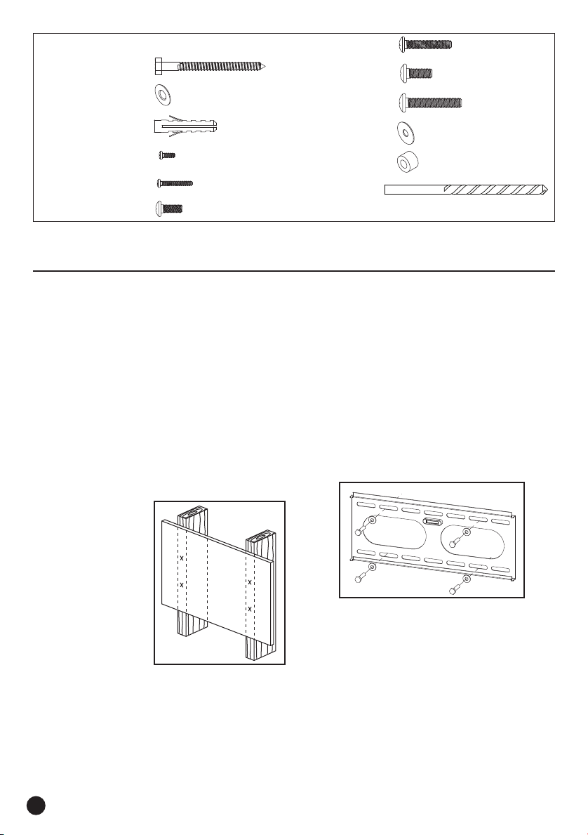
Hardware Kit
(A) M8 x 63 Lag Bolt (x4)
(B) Lag Bolt Washer (x4)
(C) Concrete Anchor (x4)
(D) M4 x 12 Bolt (x4)
(E) M4 x 20 Bolt (x4)
(F) M6 x 12 Bolt (x4)
(G) M6 x 30 Bolt (x4)
(H) M8 x 12 Bolt (x4)
(I) M8 x 30 Bolt (x4)
(J) M6 Washer (x4)
(K) Spacer (x8)
(L) 3/16” Drill Bit
Mounting the wall plate
Drywall Installation
Important! For safety reasons, this mount must be secured to at least two wood studs no less than 16” apart.
The studs must be capable of supporting the combined weight of the mount and display.
1. Use a high quality stud fi nder to locate two adjacent
studs where you wish to install your mount. Mark
both edges of each stud to help identify the exact
center.
NOTE: You must use the center of each stud
to avoid cracking or splitting the wood during
installation.
2. Place the wall plate against the wall and level it
using the integrated bubble level.
3. While another
person holds
the wall plate in
position, mark four
locations (two per
stud) for securing
the mount to the
wall (see Fig.1).
Fig.1
4. Set the wall plate aside and drill a 3/16” pilot hole at
each marked location.
5. Place the wall plate back against the wall and
attach it using the lag bolts (A) and lag bolt washers
(B) (see Fig. 2). Do not over-tighten these bolts
and do not release the wall plate until all bolts
are in place. Ensure that the wall plate remains
level after all bolts are secured.
Fig.2
2
Page 3

Concrete/Brick Installation
IMPORTANT! For safety reasons, the concrete wall must be capable of supporting the combined weight of
the mount and the display. The manufacturer takes no responsibility for failure caused by walls of insuffi cient
strength.
1. Place the wall plate against the wall in the desired
location and level it using the integrated bubble
level.
2. While another
person holds the
wall plate in place,
mark four evenly
spaced locations on
the wall for securing
the mount (see Fig.
3).
Fig.3
3. Set the wall plate aside and drill a 10 mm (3/8”) hole
at each marked location. Remove any excess dust
from the holes.
4. Insert a Concrete
Anchor (C) into each
hole so that it is fl ush
with the concrete
surface (see Fig. 4).
A hammer can be
used to lightly tap
the anchors into
place if necessary.
Fig.4
5. Place the wall plate back against the wall and
attach it using the lag bolts (A) and lag bolt washers
(B) (see Fig. 2). Do not over-tighten these bolts and
do not release the wall plate until all bolts are in
place. Ensure that the wall plate remains level after
all bolts are secured.
Attaching the Arms to the TV
IMPORTANT! Use extra care during this part of the installation. If possible, avoid placing your display facedown
as it may damage the viewing surface.
NOTE: This mount comes with a selection of different screw diameters and lengths to accommodate a wide
variety of display models. Not all of the hardware in the kit will be used.
1. Determine the correct length of screw to use by
examining the back of your display:
A. If the back of your display is fl at and the
mounting holes are fl ush with the surface, you
will use the shorter screws (D, F, or H) from the
hardware kit.
B. If the back of your display is curved, has
a protrusion, or if the mounting holes are
recessed, you will need to use the longer screws
(E, G, or I) and spacers (K).
2. Determine the correct diameter of screw to use
by carefully trying one of each size (M4, M6, and
M8) from the hardware kit. Do not force any
of the screws – if you feel resistance stop
immediately and try a smaller diameter screw.
3. Find the tilt adjustment rod and remove one the tilt
adjustment knobs using a screwdriver (see Fig.5).
Place the knob and screw in a safe location.
4. Pass the tilt adjustment rod through both arms
as shown in Fig.6. Make sure the long part of the
tilt adjustment knob faces downwards, exactly as
shown. Replace the missing tilt adjustment knob
using a screwdriver. The fi nal assembly should
match Fig.7.
Fig.6
Continues on next page...
English
Fig.5
3
Page 4

Fig.7
1
2
3
1
2
5. Remove the clips located towards the top of each
arm and take out the pins (see Fig.8). Then push
down and hold both tilt adjustment rod knobs
simultaneously. Lift both sides of the rod together
and open both arms completely as shown in Fig.9.
Fig.8 Fig.9
7. Attach the mount arms to the back of your display
using the screws identifi ed in Steps 1 and 2 (see
Fig.11):
A. If you are using the M4 or M6 screws you will
also need to use the M6 washers (J). M8 screws
do not require washers.
B. If you are using the longer screws on a display
with a curved or recessed back, you will also
need to use the spacers (K). Use one spacer or
two spacers stacked as needed. You should
only use a spacer if necessary.
For displays
with flat backs.
For displays with
curved or
recessed backs.
Fig.11
8. Close the mount arms by returning them to the
original position. Insert the pin and replace the
clip on both arms (see Fig.12). Make sure the tilt
adjustment rod is turned to the locked position
by rotating the knobs away from the display. The
mount arms must be fully closed and locked
before moving on to the next part.
6. Place the opened
arms over the back
of your display. Adjust
the arms along the
length of the tilt
adjustment rod so
that they line up with
the mounting holes
on back of your
display. The hinges on
the arms should be
located towards the
bottom of the display
(see Fig.10).
4
Fig.12
Fig.10
Page 5

Final Installation
1. With the help of another person, carefully lift your display and place it on the wall plate. Do not release the
display until the mount arms have securely hooked onto the wall plate.
2. Insert the safety bar at the bottom of the mount to
prevent the display from being lifted from the wall
plate. A padlock can be inserted into the end of the
bar to help prevent theft of your display (see Fig.13).
IMPORTANT! The safety bar must be used at all
times to prevent the display from being accidentally
knocked from the mount.
Fig.13
Padlock (optional,
not included)
Safety Bar
Operation and Adjustment
To change the tilt angle of your display: Hold the display fi rmly with one hand and rotate one of the tilt
adjustment knobs towards the display to unlock the tilt. Carefully move the display to the desired position and
return the knob to its original position to lock it in place. Do not release the display until the tilt is locked in
place.
Periodically clean your mount with a dry cloth. Inspect all screws and hardware at regular intervals to ensure that
no connections have become loose over time. Re-tighten as necessary.
Specifi cations
Display Size: 26” to 40”
Maximum Load: 45 kg (100 lbs)
Universal VESA Mounting Pattern: 400 mm x 400 mm
(15.7” x 15.7“) max
Tilt Range: 15° down
Profi le: 4.5 cm (1.8”)
English
5
Page 6

Limited Lifetime Warranty
Audiovox Elect ronics Corporat ion (the “Company”) warran ts to you the origi nal retail pu rchaser of th is product that sho uld it, under norma l use and
conditi ons, be proven defec tive in materia l or workmanship du ring its life time while you ow n it, such defect(s) wil l be repaired or r eplaced (at the
Company’s option) w ithout charge fo r parts and repa ir labor.
To obtain repa ir or replacement w ithin the te rms of this Warra nty, the product is to be de livered with proo f of warranty coverag e (e.g. dated bi ll of sale),
specifi cat ion of defect(s), transp ortation prepa id, to the Company at th e address shown below. Do not re turn thi s product to the Reta iler.
This Warra nty does not cover produc t purchased, s erviced or used out side the United State s or Canada.
This Warra nty is not tran sferable and does not ex tend to costs inc urred for inst allation, remov al or reinstal lation of the produc t. This Warranty do es not
apply if in t he Company’s opinion, t he product has been da maged throug h alteration, improp er install ation, mishand ling, misu se, neglect, or accident.
THE EXTEN T OF THE COMPANY’S LIABILITY UNDER T HIS WARRA NTY IS LIMITED TO T HE REPAIR OR REPL ACEMENT PROVIDE D ABOVE
AND, IN NO EVENT, SHALL THE COM PA NY’S LIABILITY EXCEED THE PU RCHASE PR ICE PAID BY PURCHASE R FOR THE PRODUCT.
This Warra nty is in lieu of a ll other expres s warranties or l iabilities. A NY IMPLIED WARRANTIE S, INCLUDING ANY IMPLIED WARRANT Y OF
MERCHANTABILIT Y OR FITNESS FOR A PARTICULAR PUR POSE SHALL BE LIMITED TO DURATION OF TH IS WARRA NTY. IN NO CASE SHALL
THE COMPANY BE LIABLE FOR ANY CONSEQU ENTIAL OR INCIDENTAL DAMAGES WHATSOEVER . No person or repre sentative is author ized to
assume f or the Company any li ability othe r than expres sed herein in co nnection wit h the sale of th is product.
Some state s/provinces do no t allow limitat ions on how long an impl ied warranty la sts or the exclusi on or limitation of i ncidental or con sequential da mage
so the above l imitation s or exclusions may not apply to yo u. This Warranty g ives you specifi c legal rights an d you may also have other r ights which var y
from state/province to state/province.
U.S.A .: Audiovox Electron ics Corporation, 150 Ma rcus Blvd., Hauppauge, New York 11788
CANADA: Audiovox Retu rn Center, c/o Genco, 668 5 Kennedy Road, Unit 3, Door 16, Mis sissauga, Onta rio L5T 3A5
Garantie à vie limitée
Audiovox Elect ronics Corporat ion (l’« Entrep rise ») vous garantit en t ant qu’acheteur de déta il d’orig ine du présent produ it que, s’il présente de s défauts
de matièr e ou de fabrication da ns des condition s d’util isation norma les pendant sa dur ée de vie alors que vou s en êtes propriét aire, ce/ces défaut (s) feront
l’objet d’une répara tion ou d’un remplacement (à la d iscrétion de l’E ntreprise) san s frais pour le s pièces et pour les h eures de main- d’œuvre.
Pour obten ir une réparat ion ou un remplacement e n vertu des terme s de la présente gara ntie, le produit doit êt re livré à l’Entre prise avec preuve de
couvert ure de garantie (c’est-à-d ire une preuve d’achat daté e), une des cription du ou des déf auts, et les frais de t ransport payés d’avance, à l’adres se
indiqué e ci-dessous. Ne pa s retourner ce pr oduit chez le déta illant.
La présen te garantie ne couv re pas de produit ache té, réparé ou util isé à l’extérieur des Ét ats-Unis ou du Cana da.
La présent e garantie ne peut pa s être trans férée et ne couvre pa s les frais encou rus pour l’inst allation, l’enlèveme nt ou la réinsta llation du produit. La
présent e garantie ne s’applique pas si , selon l’avis de l’Entrepr ise, le produit a été endo mmagé suite à une mod ifi cation, u ne install ation incorrec te, une
manipu lation incorre cte, une mauvaise ut ilisation , une négligence ou u n accident.
L’ÉTENDUE DE LA RESPONSABILITÉ DE L’ENTREPR ISE EN VERTU DE LA PRÉSENTE GA RANTIE EST LIMI TÉE À LA RÉPARATION OU AU
REMPLACEMENT I NDIQUÉS CI-DESSUS ET, EN AUCUN CAS, LA RESPONSABILI TÉ DE L’ENTREPR ISE NE PEUT DÉPASSER LE PRIX D’ACHAT
PAYÉ PAR L’ACHETEU R POUR LE PRODUIT.
Cette ga rantie remplace tout e autre garantie ou r esponsabil ité expresse. TOUTE G ARANTIE IMPLICI TE, INCLUANT TOUTE GARANTI E IMPLICITE DE
QUALITÉ MARCHAN DE OU D’ADAPTATION À UN USAGE PARTICULIER EST LIM ITÉE À LA DURÉE DE LA PRÉSENT E GARANTIE. EN AUCUN
CAS L’ENTREPRISE NE PE UT ÊTRE RESPONSABLE POUR UN QU ELCONQUE DOMMAGE CONSÉCUTIF OU IN DIRECT. Aucune person ne ou aucun
représ entant n’est autorisé à ass umer pour l’entrepri se une quelconque r esponsabil ité autre que celle ex primée dans le s présentes en re lation avec la vente
de ce produit.
Certa ines juridic tions n’autorisent pas de l imites quant à la du rée d’une garantie i mplicite ou quant à l’exclusi on ou la limitatio n de dommages indir ects ou
conséc utifs; les li mitations et exc lusions indiqué es dans les pré sentes pourra ient donc ne pas s’appliquer à votre c as. Cette gara ntie vous donne de s droits
légaux spécifi q ues et vous pourr iez également jou ir d’autres d roits qui varie nt d’une ju ridiction à l’autre.
É-U : Audiovox El ectronics Cor poration, 150 Marc us Blvd., Hauppauge, New York 11788
CANADA : Audiovox R eturn Center, c/o Genco, 6685 Kenn edy Road, Unit 3, Door 16, Missis sauga, Ontario L5T 3A5
Garantía Limitada Durante la Vida Útil del Producto
Audiovox Elect ronics Corporat ion (la “Compañía”) le gara ntiza a usted, el c omprador original d e este producto que si, baj o condiciones y uso n ormales,
se encont rara que presenta d efectos materi ales o de mano de obra dur ante su vida útil m ientras sea de su pro piedad, tales defe ctos serán repa rados o
reempla zados (a opción de la Compañ ía) sin cargo alg uno por las piezas y l abores de reparac ión.
Para obtene r los servicios de r eparación o reempla zo dentro de los tér minos de esta Gar antía, el producto s e entregará con pr ueba de cubierta de garantía
(por ejemplo, fac tura fechada de ve nta), especifi ca ción de los defectos , transporte p repagado, a la Compañía a la d irección ind icada abajo. No devuelva e ste
producto al Distribuidor.
Esta Gara ntía no cubre un pr oducto adquirido, ma ntenido o utili zado fuera de los Estados Un idos o Canadá.
Esta Gara ntía no es tran sferible y no incluye los c ostos incur ridos en la insta lación, remoci ón o reinstalac ión de este producto. Es ta Garantía no aplic a si, es
opinió n de la Compañía que, est e producto ha sufr ido daños debido a alterac iones, insta lación inadec uada, abuso, uso ind ebido, negligencia o acc idente.
EL ALCANCE DE LA RESP ONSABILIDAD DE LA COMPAÑÍA BAJO ESTA GARANT ÍA ESTÁ LIMITADO A LA REPARACIÓN O EL REEMPLAZO
PROVISTO ARRI BA Y, EN NINGÚN CASO, DEBERÁ L A RESPONSABILIDAD DE LA COMPAÑÍA EXCEDER EL PRECIO DE COMPRA PAGADO POR
EL COMPRADOR DE ESTE PRODUCTO.
Esta Gara ntía reemplaza c ualesquiera o tras respons abilidades o gara ntías expres as. CUALESQUIERA GARA NTÍAS IMPLÍCITAS, INCLUYE NDO
CUALQUIER GARA NTÍA IMPLÍCITA DE COMERCIABILI DAD O ADAPTABILIDAD PARA UN PROPÓSITO EN PARTICULA R ESTARÁN LIMITADAS
A LA DURACIÓN DE ESTA GARANT ÍA. EN NINGÚN CASO LA COMPAÑÍA SER Á RESPONSABLE POR DAÑOS EMERGENTES O INCIDEN TALES.
Ningu na persona ni re presentante e stá autorizado a asu mir, a nombre de la Compañ ía, ningu na responsabi lidad salvo la expr esada aquí en conexión con
la venta de este p roducto.
Algun os estados/provincias no pe rmiten lim itaciones sobre la du ración de una gara ntía implícit a o la exclusión o la lim itación de daños incident ales
o emergente s, de modo que es posible qu e las limitaci ones o exclusiones a nteriores no aplique n en su caso. Esta Gar antía le confi ere derechos legales
específi cos; se gún el estado/provincia, p uede disfruta r además de otros de rechos.
EE.UU.: Audiovox Electro nics Corporatio n, 150 Marcus Blvd., Hauppauge, New York 11788
CANADÁ:: Audiovox Retur n Center, c/o Ge nco, 6685 Kennedy Road, Un it 3, Door 16, Mississauga, O ntario L5T 3A5
© 2010 Audiovox Accessories Corporation
Trademark (s) Registered, Marqu es Déposées, Ma rcas Registradas.
All other brands and product names a re trademarks or registered trademarks of their respective owners. / Toutes les autres marques et tous les autres
noms de produits sont des marques de commerce ou des marques de commerce déposées de leu rs propr iétaires respe ctifs. / Todas las demás marcas
y nombres de productos son marcas com ercial es o marcas comerciales registradas de sus respec tivos dueños.
www.rcaaccessories.com MAF75BKR_US_IB_02
 Loading...