

Page 1
Follow these precautions to ensure safe installation and mounting of your fl at panel TV.
1. Be sure you have purchased the correct wall mount for your TV. Recheck the
size and weight constraints.
2. Gather all necessary tools before you begin installation. You will need a #3 bit
Phillips screwdriver, electric drill, drill bit (included), level (integrated level on
product), stud fi nder, and hammer (for brick and concrete installations).
3. It is essential for the wall mount plate to be attached to wall studs.
(Use a stud fi nder.)
4. Use the included hardware for mounting purposes. This hardware has been
provided to ensure a safe and secure mount.
5. Hire a licensed electrician to relocate an electrical outlet, if needed.
6. Be sure to purchase wires long enough to connect the TV to the audio and
video components in your installation.
7. We recommend you hire a professional installer, if you have any concerns
about installing the TV wall mount yourself.
Keep your sales receipt to obtain warranty parts and service and for proof of
purchase. Attach it here and record the model number.
Model No. _____________________________________________________________
Purchase Date: _________________________________________________________
Dealer/Address/Phone __________________________________________________
Safety precautions
Attaching wall mount plate
Drywall Installation
1. Use a stud fi nder to locate a wood stud where you want to install the mount.
NOTE: It is required that the wall mount plate be attached to wall studs.
2. Locate center of stud.
3. Place the wall mount plate against the wall, with the cord management
channel towards the bottom. Level it using the bubble guide. Mark the
locations on the wall where the mount is to be installed.
4. Drill holes at each marked location using the enclosed wood drill bit.
5. Secure the wall mount plate to the wall, using one drywall screw, but do not
completely tighten it yet.
6. Using the integrated bubble level, carefully adjust the wall mount plate until it
is level.
7. Insert the remaining screws and tighten all three screws completely.
Concrete/Brick Installation
1. Place the wall mount plate against the wall with the cord management
channel towards the bottom.
2. Using the integrated bubble level, mark off the position of the holes that will be
used for securing the mount.
3. Place the wall mount plate aside.
4. Using an electric drill and a 5/16" (8mm) masonry bit, drill holes in the marked
locations.
5. Remove any excess dust from the holes.
6. Insert a concrete anchor into each hole. If necessary, use a hammer to lightly
tap each anchor into place so they are fl ush with the wall.
7. Once both anchors are in place, place the wall mount plate back into position.
Using the integrated bubble level, carefully adjust the wall mount plate until it
is level.
8. Attach the wall mount plate, using the drywall screws provided.
9. Make sure all screws are tightened and secure.
1. Unplug your fl at panel TV before starting this step of the installation.
IMPORTANT: NEVER lay the TV face down as this may cause damage to the
viewing surface.
2. Before attaching the TV mount plate to the TV, determine which hardware to
use. Examine the back of your TV. If the back is fl at, use the M4x12mm bolts.
If your TV has a recessed back, use the longer M4x30mm bolts and 1/2"
spacers.
3. After you have determined which bolts to use, attach the TV mount plate to
the back of your TV.
NOTE: Be careful not to over-tighten the bolts.
Attaching the TV mount plate
Attaching the TV mount plate to the wall
mount plate
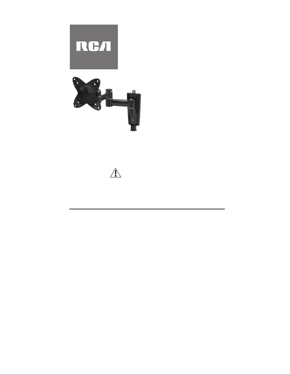
Thank you for choosing a Universal
Flat Panel TV Wall Mount from RCA.
This mount can be used for all major
brands of 13" - 27" fl at panel TVs,
40 lbs (18 kg) or under. This wall
mount features a 0-15-degree tilt,
180-degree pan and swivel, and
double swing arm extension for easy
viewing. Before attempting to mount
your television set, please remove
all parts from this package and read
the installation instructions carefully.
MAF40BKR
WARNING: Use of this mount with a TV weighing over 40 lbs. or with a
screen larger than 27" could cause the mount to fail causing property
damage and/or personal injury.
fl at panel solutions
LCD TV Wall Mount
Installation Manual
Fits TVs 13"- 27"
Maximum Load Capacity – 40 lbs. (18 kg)
CAUTION:
This wall mount is intended for use only with the maximum weight of
18 kg/40 lbs. Use with heavier than the maximum weights indicated may
result in instability causing possible injury. Follow the installation and
operation instructions carefully.
Page 2
Dealer/Address/Phone __________________________________________________
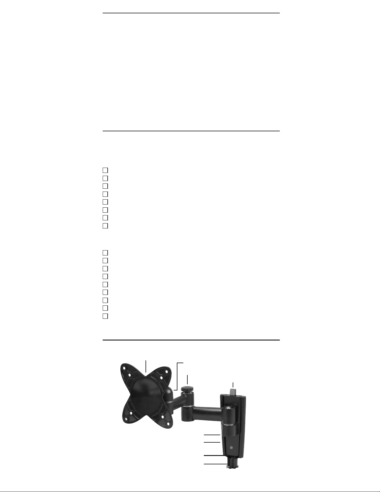
Product diagram
1. To complete the installation, slide the TV mount plate with your TV attached
into the wall mount plate.
2. The retainer clip on the top of the wall mount plate should click, indicating that
the mount is secure.
3. To remove the TV, push in on the clip and slide the TV mount plate up.
4. For additional security and stability, insert the security bolt into the hole
located at the base of the unit.
5. Tighten, using the Allen Wrench provided.
Attaching the TV mount plate to the wall
mount plate
Model: MAF40BKR
Two-piece, low-profi le design
Description: RCA Universal LCD TV Wall
Mount with Swing Arm Extension
TV Size Range: 13" – 27"
Max. Load: 40 lbs. (18kg)
Min. Profi le: 2.7" (6.9 cm)
Max. Extension: 9.6" (24.4 cm)
Tilt: +/- 0-15°
Swivel: 180°
VESA Compliant: 100/100
Integrated Bubble Level / Cord Management System
Specifi cations
You r RCA Flat Pa nel T V Wal l Mount fe atu res an ad jus tabl e 15 -de gree til t a nd
180 -degree pan and sw ivel acti on for e asy viewing.
To adj ust the til t:
1. Locate the adjustment knob directly behind the TV mounting point.
2. Loosen the knob by turning it counter-clockwise.
3. Adjust the tilt to the desired level and re-tighten the knob to lock the
adjustment in place.
To adj ust the sw ive l:
1. Simply move the extension arm into the desired position.
2. If the joint is too tight or too loose, adjust the tightness of the joint.
3. Locate the knob closest to the wall.
4. Turn the knob counter-clockwise to loosen and clockwise to tighten.
Operation and adjustment
TV Mount Plate
Before beginning the installation process, verify that you have all the necessary tools
on hand. The following tools are required for proper installation:
Too ls
#3 bit Phillips screwdriver
Stud fi nder
Electric drill
Drill bit (included)
5/16" (8mm) masonry drill bit for concrete/brick installation
Level (integrated level on product)
Allen Wrench (included)
Hammer (for concrete installations)
Package Contents
Make sure all the hardware has been included with your mount.
(1) Drill Bit
(3) 1-7/8" Drywall Screws
(3) Concrete Anchors
(2) Allen Wrenches
(4) M4x12mm Bolts
(4) M4x30mm Bolts
(4) 1/2" Spacers
(1) Security Bolt
(1) Phillips-Head Driver
Preparing to install
Adjustment Knob
Double Swing Arm Extension
Wall Mount Plate
Integrated Bubble Level
Retainer Clip
Security Bolt Position
Cord Management Channel
Limited Lifetime Warranty
Audiovox Electronics Corporation (the “Company”) warrants to you the original
retail purchaser of this product that should it, under normal use and conditions,
be proven defective in material or workmanship during its lifetime while you own
it, such defect(s) will be repaired or replaced (at the Company’s option) without
charge for parts and repair labor.
To obta in repa ir or rep laceme nt w ith in the te rms of this Warrant y, th e p rod uct is to
be delivered with proof of warranty coverage (e.g. dated bill of sale), specifi cation
of defect(s), transportation prepaid, to the Company at the address shown below.
Do not return this product to the Retailer.
This Warranty does not cover product purchased, serviced or used outside the
United States or Canada.
This Warranty is not transferable and does not extend to costs incurred for
installation, removal or reinstallation of the product. This Warranty does not apply
if in the Company’s opinion, the product has been damaged through alteration,
improper installation, mishandling, misuse, neglect, or accident.
THE EXTENT OF THE COMPANY’S LIABILITY UNDER THIS WARRANTY IS
LIMITED TO THE REPAIR OR REPLACEMENT PROVIDED ABOVE AND, IN NO
EVENT, SHALL THE COMPANY’S LIABILITY EXCEED THE PURCHASE PRICE
PAID BY PURCHASER FOR T HE PRODUCT.
This Warranty is in lieu of all other express warranties or liabilities. ANY IMPLIED
WARRANTIES, INCLUDING ANY IMPLIED WARRANTY OF MERCHANTABILITY
OR FITNESS FOR A PARTICULAR PURPOSE SHALL BE LIMITED TO DURATION
OF THIS WARRANTY. IN NO CASE SHALL THE COMPANY BE LIABLE FOR ANY
CONSEQUENTIAL OR INCIDENTAL DAMAGES WHATSOEVER. No person or
representative is authorized to assume for the Company any liability other than
expressed herein in connection with the sale of this product.
Some states/provinces do not allow limitations on how long an implied warranty
lasts or the exclusion or limitation of incidental or consequential damage so the
above limitations or exclusions may not apply to you. This Warranty gives you
specifi c legal rights and you may also have other rights which vary from state/
province to state/province.
U.S.A.: Audiovox Electronics Corporation, 150 Marcus Blvd.,
Hauppauge, New York 11788
CANADA: Audiovox Return Center, c/o Genco, 6685 Kennedy Road, Unit 3, Door
16, Mississauga, Ontario L5T 3A5
Trademark(s) Registered
All other brands and product names are trademarks or registered trademarks of
their respective owners.
© 2010 Audiovox Accessories Corporation
www.rcaaccessories.com MAF40BKR_US_IB_03
Page 3

Attaching wall mount plate
Drywall Installation
1. Use a stud fi nder to locate a wood stud where you want to install the mount.
NOTE: It is required that the wall mount plate be attached to wall studs.
2. Locate center of stud.
3. Place the wall mount plate against the wall, with the cord management
channel towards the bottom. Level it using the bubble guide. Mark the
locations on the wall where the mount is to be installed.
4. Drill holes at each marked location using the enclosed wood drill bit.
5. Secure the wall mount plate to the wall, using one drywall screw, but do not
completely tighten it yet.
6. Using the integrated bubble level, carefully adjust the wall mount plate until it
is level.
7. Insert the remaining screws and tighten all three screws completely.
Concrete/Brick Installation
1. Place the wall mount plate against the wall with the cord management
channel towards the bottom.
2. Using the integrated bubble level, mark off the position of the holes that will be
used for securing the mount.
3. Place the wall mount plate aside.
4. Using an electric drill and a 5/16" (8mm) masonry bit, drill holes in the marked
locations.
5. Remove any excess dust from the holes.
6. Insert a concrete anchor into each hole. If necessary, use a hammer to lightly
tap each anchor into place so they are fl ush with the wall.
7. Once both anchors are in place, place the wall mount plate back into position.
Using the integrated bubble level, carefully adjust the wall mount plate until it
is level.
8. Attach the wall mount plate, using the drywall screws provided.
9. Make sure all screws are tightened and secure.
1. Unplug your fl at panel TV before starting this step of the installation.
IMPORTANT: NEVER lay the TV face down as this may cause damage to the
viewing surface.
2. Before attaching the TV mount plate to the TV, determine which hardware to
use. Examine the back of your TV. If the back is fl at, use the M4x12mm bolts.
If your TV has a recessed back, use the longer M4x30mm bolts and 1/2"
spacers.
3. After you have determined which bolts to use, attach the TV mount plate to
the back of your TV.
NOTE: Be careful not to over-tighten the bolts.
Attaching the TV mount plate
Suivez ces précautions pour installer et la fi xer au téléviseur à écran plat en toute sécurité.
1. Assurez-vous que la fi xation murale achetée convient à votre téléviseur. Vérifi ez
de nouveau les limites de dimensions et de poids.
2. Rassemblez les outils nécessaires avant d'entreprendre l'installation. Vous
aurez besoin d'un tournevis Phillips à lame no 3, d'une perceuse électrique,
d'une mèche (incluse), d'un niveau (intégré au produit), d'un localisateur de
montants et d'un marteau (pour les installations sur brique et béton).
3. Vous devez absolument fi xer la fi xation murale aux montants du mur. (Utilisez
un localisateur de montants.)
4. Utilisez le matériel fourni pour la fi xation. Ce matériel garantit une installation
sûre et sécuritaire.
5. Demandez à un électricien compétent de déplacer une prise de courant
au besoin.
6. N'oubliez pas d'acheter des fi ls suffi samment longs pour raccorder le téléviseur
aux appareils audio et vidéo dans votre installation.
7. Nous recommandons de faire appel aux services d'un installateur professionnel
si vous craignez de ne pouvoir installer la fi xation murale du téléviseur seul.
Conservez votre coupon de caisse pour obtenir les pièces et le service sous
garantie et comme preuve d'achat. Fixez-le ici et inscrivez le numéro de modèle.
Mesures de précaution
Merci d'avoir choisi une fi xation
murale pour téléviseur à écran plat
universelle RCA. Cette fi xation est
compatible avec toutes les grandes
marques de téléviseurs à écran
plat de 13 à 27 po, de 40 lb (18
kg) et moins. Cette fi xation murale
comprend un dispositif d'inclinaison
de 0-15 degrés et de panoramique
et de pivotement de 180 degrés
qui facilite le visionnement. Avant
de tenter de fi xer le téléviseur en place, retirez toutes les pièces de
l'emballage et lisez attentivement les instructions d'installation.
AVERTISSEMENT : Toute utilisation de ce support avec un téléviseur d’un
poids supérieur à 40 lb (18 kg), ou dont la taille de l’écran est supérieure à
27 po, peut provoquer une défaillance du support et par conséquent des
dommages matériels et (ou) des blessures corporelles.
MAF40BKR
solutions écran plat
Support mural pour TV LCD
Manuel d'installation
Pour téléviseurs de 13 à 27 po
Capacité de charge maximale – 40 lb (18 kg)
Ce support mural est conçu pour supporter un poids maximal de
18 kg/40 lb. Son utilisation avec un poids supérieur au maximum
indiqué pourrait causer de l’instabilité et des blessures. Respectez
soigneusement les instructions d’installation et d’utilisation.
MISE EN GARDE :
Page 4

NOTE: Be careful not to over-tighten the bolts.
1. To complete the installation, slide the TV mount plate with your TV attached
into the wall mount plate.
2. The retainer clip on the top of the wall mount plate should click, indicating that
the mount is secure.
3. To remove the TV, push in on the clip and slide the TV mount plate up.
4. For additional security and stability, insert the security bolt into the hole
located at the base of the unit.
5. Tighten, using the Allen Wrench provided.
Attaching the TV mount plate to the wall
mount plate
You r R CA F lat Pa nel TV Wa ll Mo unt fe atu res an a dju stab le 15-d egre e t ilt an d
180 -degree p an and swi vel ac tion for e asy vi ewing.
To ad jus t t he ti lt :
1. Locate the adjustment knob directly behind the TV mounting point.
2. Loosen the knob by turning it counter-clockwise.
3. Adjust the tilt to the desired level and re-tighten the knob to lock the
adjustment in place.
To ad jus t t he sw ive l:
1. Simply move the extension arm into the desired position.
2. If the joint is too tight or too loose, adjust the tightness of the joint.
3. Locate the knob closest to the wall.
4. Turn the knob counter-clockwise to loosen and clockwise to tighten.
Operation and adjustment
Modèle : MAF40BKR
Design en deux pièces surbaissé
Description : Fixation murale pour téléviseur à écran plat universelle
RCA à bras d'extension pivotant
Dimensions de téléviseur : 13 à 27 po
Charge maximale : 40 lb (18 kg)
Profi l min. : 2,7 po (6,9 cm)
Extension max. : 9,6 po (24,4 cm)
Inclinaison : +/- 0-15 °
Pivotement : 180 °
Conforme VESA : 100/100
Niveau à bulle intégré / Système guide-cordon
Fiche technique
si vous craignez de ne pouvoir installer la fi xation murale du téléviseur seul.
Conservez votre coupon de caisse pour obtenir les pièces et le service sous
garantie et comme preuve d'achat. Fixez-le ici et inscrivez le numéro de modèle.
No de modèle ___________________________________________________________
Date d'achat : ___________________________________________________________
Détaillant/adresse/téléphone ______________________________________________
Schéma du produit
Plaque de fi xation du téléviseur
Bouton d'ajustement
Bras d'extension pivotant double
Plaque de fi xation murale
Niveau à bulle intégré
Bague de maintien
Position de boulon de sécurité
Guide-cordon
Avant d'entreprendre l'installation, assurez-vous d'avoir tous les outils nécessaires en
main. Les outils suivants sont nécessaires pour réaliser une installation appropriée :
Outils
Tournevis Phillips à lame no 3
Localisateur de montants
Perceuse électrique
Mèche (incluse)
Mèche à maçonnerie de 5/16 po (8 mm) pour béton/brique
Niveau (intégré au produit)
Clé Allen (incluse)
Marteau (pour installations sur béton)
Contenu de l'emballage
Assurez-vous que tout le matériel est inclus avec la fi xation.
(1) Mèche
(3) Vis à placoplâtre de 1 7/8 po
(3) Ancrages de béton
(2) Clé Allen
(4) Boulons M4 x 12 mm
(4) Boulons M4 x 30 mm
(4) Entretoises de 1/2 po
(1) Boulon de sécurité
(1) Outil pour vis Phillips
Préparation pour l'installation
Limited Lifetime Warranty
Audiovox Electronics Corporation (the “Company”) warrants to you the original
retail purchaser of this product that should it, under normal use and conditions,
be proven defective in material or workmanship during its lifetime while you own
it, such defect(s) will be repaired or replaced (at the Company’s option) without
charge for parts and repair labor.
To obt ain re pa ir or re plac em ent wi thi n t he ter ms of th is War rant y, t he pro duct is to
be delivered with proof of warranty coverage (e.g. dated bill of sale), specifi cation
of defect(s), transportation prepaid, to the Company at the address shown below.
Do not return this product to the Retailer.
This Warranty does not cover product purchased, serviced or used outside the
United States or Canada.
This Warranty is not transferable and does not extend to costs incurred for
installation, removal or reinstallation of the product. This Warranty does not apply
if in the Company’s opinion, the product has been damaged through alteration,
improper installation, mishandling, misuse, neglect, or accident.
THE EXTENT OF THE COMPANY’S LIABILIT Y UNDER THIS WARRANTY IS
LIMITED TO THE REPAIR OR REPLACEMENT PROVIDED ABOVE AND, IN NO
EVENT, SHALL THE COMPANY’S LIABILITY EXCEED THE PURCHASE PRICE
PAID BY PURCHASER FOR THE PRODUCT.
This Warranty is in lieu of all other express warranties or liabilities. ANY IMPLIED
WARRANTIES, INCLUDING ANY IMPLIED WARRANTY OF MERCHANTABILITY
OR FITNESS FOR A PARTICULAR PURPOSE SHALL BE LIMITED TO DURATION
OF THIS WARRANTY. IN NO CASE SHALL THE COMPANY BE LIABLE FOR ANY
CONSEQUENTIAL OR INCIDENTAL DAMAGES WHATSOEVER. No person or
representative is authorized to assume for the Company any liability other than
expressed herein in connection with the sale of this product.
Some states/provinces do not allow limitations on how long an implied warranty
lasts or the exclusion or limitation of incidental or consequential damage so the
above limitations or exclusions may not apply to you. This Warranty gives you
specifi c legal rights and you may also have other rights which vary from state/
province to state/province.
U.S.A.: Audiovox Electronics Corporation, 150 Marcus Blvd.,
Hauppauge, New York 11788
CANADA: Audiovox Return Center, c/o Genco, 6685 Kennedy Road, Unit 3, Door
16, Mississ auga, On tario L5T 3A5
Trademark(s) Registered
All other brands and product names are trademarks or registered trademarks of
their respective owners.
© 2010 Audiovox Accessories Corporation
www.rcaaccessories.com MAF40BKR_US_IB_03
 Loading...