

Page 1
fl at panel solutions
LCD TV Wall Mount
Installation Manual
MAF15BKR
Fits TVs 15”- 32”
Maximum Load
Capacity – 55 lb (25 kg)
Thank you for choosing the RCA MAF15BKR Universal Flat Panel
TV Wall Mount. This mount can be used for all major brands of
15" - 32" fl at panel TVs, 55 lbs (25 kg) or under. Before attempting
to mount your television set, please remove all parts from this
package and read the installation instructions carefully.
WARNING: Use of this mount with a TV weighing over 55
lbs. or with a screen larger than 32" could cause the mount
to fail causing property damage and/or personal injury.
CAUTION:
This wall mount is intended for
use only with the maximum
weight of 25 kg/55 bls. Use with
heavier than the maximum weights
indicated may result in instability
causing possible injury. Follow
the installation and operation
instructions carefully.
Safety precautions
Follow these precautions to ensure safe installation and mounting of your fl at panel TV.
1. Read these instructions carefully before you begin.
If you are unsure of any part of the process, contact
a professional contractor or installer for assistance.
Improper installation can result in injury or damage.
2. The wall or mounting surface must be capable of
supporting the combined weight of the mount and
the display; if not, the structure must be reinforced.
3. Safety gear and proper tools must be used. Failure
to do so can result in injury and/or damage. A
minimum of two people are required for installation.
Do not attempt to install this mount alone under any
circumstances.
4. Follow all instructions and recommendations
regarding adequate ventilation and suitable
locations for mounting your display. Consult the
owner‘s manual for your particular display for more
information.
5. For drywall installation, it is essential for the
wall mount plate to be attached to wall studs.
(Use a stud fi nder.)
6. Use the included hardware for mounting purposes.
This hardware has been provided to ensure a safe
and secure mount.
7. Hire a licensed electrician to relocate an electrical
outlet, if needed.
8. Be sure to purchase wires long enough to connect
the TV to the audio and video components in your
installation.
Keep your sales receipt to obtain warranty parts and
service and for proof of purchase. Attach it here and
record the model number. This number is located on
the product.
Model No. _____________________________________
Purchase Date: _________________________________
Dealer/Address/Phone __________________________
Preparing to install
Before beginning the installation process, verify that you have all the necessary tools on hand. The following
tools are required for proper installation:
Tools
Phillips Head Screwdriver
Ratchet or Driver with 13 mm (1/2”) Socket
Electric or Portable Drill
3/16” (4.8 mm) Drill Bit and Stud Finder for Drywall
Installation
3/8” (10 mm) Masonry Bit for Concrete Installation
Package Contents
Wall Plate (x1)
Mount Arm (x2)
Safety Bar (x1)
Instruction Manual (x1)
Hardware Kit (x1)
Continues on next page...
Pour des instructions
en français, se
reporter à la page 4.
Para obtener
instrucciones en
español, consulte la
página 7.
Page 2
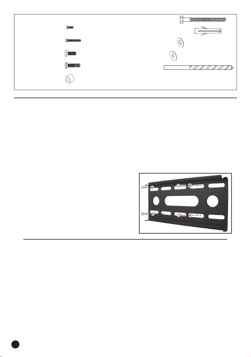
Hardware Kit
(A) M4 x 12 Screw (x4)
(F) M8 x 63 Lag Bolt (x3)
(G) Concrete Anchor (10mm, x3)
(B) M4 x 20 Screw (x4)
(C) M6 x 12 Screw (x4)
(D) M6 x 20 Screw (x4)
(E) 10mm Spacer (x4)
(H) Washer (9.5mm, x3)
(I) M6 Washer (x4)
(J) 3/16” Drill Bit
Mounting the wall plate
Drywall Installation
Important! For safety reasons, this mount must be secured to at least two wood studs no less than 16” apart.
The studs must be capable of supporting the combined weight of the mount and display.
1. Use a high quality stud fi nder to locate two adjacent
studs where you wish to install your mount. Mark
both edges of each stud to help identify the exact
center.
NOTE: You must use the center of each stud
to avoid cracking or splitting the wood during
installation.
2. Place the wall plate against the wall and level it
using the integrated bubble level.
3. While another person holds the wall plate in
position, mark four locations (two per stud) for
securing the mount to the wall.
4. Set the wall plate aside and drill a 3/16” pilot hole at
each marked location.
5. Place the wall plate back against the wall and
attach it using the lag bolts (F) and lag bolt washers
(H) (see Fig. 1). Do not over-tighten these bolts
and do not release the wall plate until all bolts
are in place. Ensure that the wall plate remains
level after all bolts are secured.
Fig.1
Concrete/Brick Installation
IMPORTANT! For safety reasons, the concrete wall must be capable of supporting the combined weight of
the mount and the display. The manufacturer takes no responsibility for failure caused by walls of insuffi cient
strength.
1. Place the wall plate against the wall in the desired
location and level it using the integrated bubble
level.
2. While another person holds the wall plate in place,
mark six evenly spaced locations on the wall for
securing the mount.
3. Set the wall plate aside and drill a 10 mm (3/8”) hole
at each marked location. Remove any excess dust
from the holes.
2
4. Insert a Concrete Anchor (G) into each hole so
that it is fl ush with the concrete surface. A hammer
can be used to lightly tap the anchors into place if
necessary.
5. Place the wall plate back against the wall and
attach it using the lag bolts (F) and lag bolt washers
(H). Do not over-tighten these bolts and do not
release the wall plate until all bolts are in place.
Ensure that the wall plate remains level after all bolts
are secured.
Page 3

Attaching the Arms to the TV
IMPORTANT! Use extra
care during this part of the
installation. If possible, avoid
placing your display facedown
as it may damage the viewing
surface.
NOTE: This mount comes
with a selection of different
screw diameters and lengths
to accommodate a wide
variety of display models. Not
all of the hardware in the kit
will be used.
Fig.2
1. Determine the correct length of screw to use by
examining the back of your display:
A. If the back of your display is fl at and the
mounting holes are fl ush with the surface, you
will use the shorter screws (A or C) from the
hardware kit.
B. If the back of your display is curved, has
a protrusion, or if the mounting holes are
recessed, you will need to use the longer screws
(B or D) and spacers (E).
Final Installation
1. With the help of another person, carefully lift your
display and place it on the wall plate. Do not
release the display until the mount arms have
securely hooked onto the wall plate.
Fig.4
2. Determine the correct diameter of screw to use by
carefully trying one of each size (M4 and M6) from
the hardware kit. Do not force any of the screws
– if you feel resistance stop immediately and try a
smaller diameter screw.
3. Attach the mount arms to the back of your display
using the M6 washers (I) and the screws identifi ed
in Steps 1 and 2 (see Fig.3)
If you are using the longer screws on a display with
a curved or recessed back, you will also need to use
the spacers (E). You should only use a spacer if
necessary.
Make sure the screws are snug, but do not
overtighten.
For displays with
flat backs.
For displays with curved or
recessed backs.
Fig.3
2. Insert the safety bar
at the bottom of the
mount to prevent the
display from being
lifted from the wall
plate. A padlock can
be inserted into the
end of the bar to help
prevent theft of your
display (see Fig.5).
IMPORTANT! The safety bar must be used at all
times to prevent the display from being accidentally
knocked from the mount.
Fig.5
English
Periodically clean your mount with a dry cloth. Inspect all screws and hardware at regular intervals to ensure
that no connections have become loose over time. Re-tighten as necessary.
Specifi cations
Display Size: 15” to 32”
Maximum Load: 25 kg (55 lbs)
Universal VESA Mounting Pattern: 230 mm x 250 mm
(9” x 9.8“) max
Profi le: 2.2 cm (0.9”)
3
Page 4

© 2010 Audiovox Accessories Corporation
Trademark(s) Registered, Marques Déposées, Marcas Registradas.
All other brands and product names are trademarks or registered trademarks of their respective owners. /
Toutes les autres marques et tous les autres noms de produits sont des marques de commerce ou des marques
de commerce déposées de leurs propriétaires respectifs. / Todas las demás marcas y nombres de productos
son marcas comerciales o marcas comerciales registradas de sus respectivos dueños.
www.rcaaccessories.com MAF15BKR_US_IB_02
 Loading...