

Page 1
User’s Guide
3922 496 30541 August 2007 v5.0
LDK 5481 + LDK 4700
SD DigiLink camera system
Page 2

LDK 5481 + LDK 4700 User’s Guide ii
Declaration of Conformity
We, Grass Valley Nederland B.V., Kapittelweg 10, 4827 HG Breda, The Netherlands, declare
under our sole responsibility that this product is in compliance with the following standards:
- EN60950-1 : Safety
- EN55103-1: EMC (Emission)
- EN55103-2: EMC (Immunity)
following the provisions of:
a. the Safety Directives 73/23//EEC and 93/68/EEC
b. the EMC Directives 89/336/EEC and 93/68/EEC
FCC Class A Statement
This product generates, uses, and can radiate radio frequency energy and if not installed and
used in accordance with the instructions, may cause interference to radio communications.
It has been tested and found to comply with the limits for a class A digital device pursuant to
part 15 of the FCC rules, which are designed to provide reasonable protection against such
interference when operated in a commercial environment.
Copyright
Trademarks
Website
Operation of this product in a residential area is likely to cause interference in which case the
user at his own expense will be required to take whatever measures may be required to correct
the interference.
Copyright Grass Valley Nederland B.V. 2007. Copying of this document and giving it to others,
and the use or communication of the contents thereof, are forbidden without express authority.
Offenders are liable to the payment of damages. All rights are reserved in the event of the grant
of a patent or the registration of a utility model or design. Liable to technical alterations in the
course of further development.
Grass Valley and Infinity are trademarks of Grass Valley, Inc. All other tradenames referenced are
service marks, trademarks, or registered trademarks of their respective companies.
Visit the Grass Valley public website to download the latest user’s guide updates and additional
information about your broadcast product:
www.thomsongrassvalley.com
Page 3

LDK 5481 + LDK 4700 User’s Guide i
Table of contents
Chapter 1 – DigiLink system
1.1 Introduction . . . . . . . . . . . . . . . . . . . . . . . . . . . . . . . . . . . . . . . . . . . . . . . . . . . . . . . . 1-1
1.2 Accessories . . . . . . . . . . . . . . . . . . . . . . . . . . . . . . . . . . . . . . . . . . . . . . . . . . . . . . . . 1-1
1.3 Compatibility . . . . . . . . . . . . . . . . . . . . . . . . . . . . . . . . . . . . . . . . . . . . . . . . . . . . . . . 1-2
1.4 Configurations . . . . . . . . . . . . . . . . . . . . . . . . . . . . . . . . . . . . . . . . . . . . . . . . . . . . . . 1-2
1.4.1 Digilink system SDI coax configuration . . . . . . . . . . . . . . . . . . . . . . . . . . . . . . 1-2
1.4.2 DigiLink system multicore configuration . . . . . . . . . . . . . . . . . . . . . . . . . . . . . 1-3
1.4.3 Stand alone SDI coax configuration . . . . . . . . . . . . . . . . . . . . . . . . . . . . . . . . . 1-4
1.4.4 Stand alone multicore configuration . . . . . . . . . . . . . . . . . . . . . . . . . . . . . . . . 1-4
1.4.5 DigiLink system hybrid fiber configuration . . . . . . . . . . . . . . . . . . . . . . . . . . . 1-5
1.4.6 DigiLink system dual fiber configuration . . . . . . . . . . . . . . . . . . . . . . . . . . . . . 1-5
1.5 Intercom . . . . . . . . . . . . . . . . . . . . . . . . . . . . . . . . . . . . . . . . . . . . . . . . . . . . . . . . . . . 1-6
Chapter 2 – DigiLink Adapter
2.1 Specifications. . . . . . . . . . . . . . . . . . . . . . . . . . . . . . . . . . . . . . . . . . . . . . . . . . . . . . . 2-5
2.2 Dimensions . . . . . . . . . . . . . . . . . . . . . . . . . . . . . . . . . . . . . . . . . . . . . . . . . . . . . . . . 2-6
2.3 Compatibility . . . . . . . . . . . . . . . . . . . . . . . . . . . . . . . . . . . . . . . . . . . . . . . . . . . . . . . 2-6
2.4 Controls . . . . . . . . . . . . . . . . . . . . . . . . . . . . . . . . . . . . . . . . . . . . . . . . . . . . . . . . . . . 2-7
2.4.1 Powering the camera. . . . . . . . . . . . . . . . . . . . . . . . . . . . . . . . . . . . . . . . . . . . 2-7
2.5 Attaching the LDK 5481 adapter to a camera head. . . . . . . . . . . . . . . . . . . . . . . . . 2-8
2.6 Mounting a script board . . . . . . . . . . . . . . . . . . . . . . . . . . . . . . . . . . . . . . . . . . . . . . 2-9
2.7 Adapter connectors . . . . . . . . . . . . . . . . . . . . . . . . . . . . . . . . . . . . . . . . . . . . . . . . . 2-10
2.7.1 SDI video output connector . . . . . . . . . . . . . . . . . . . . . . . . . . . . . . . . . . . . . . 2-11
2.7.2 SDI video input connector . . . . . . . . . . . . . . . . . . . . . . . . . . . . . . . . . . . . . . . 2-11
2.7.3 Multicore connector. . . . . . . . . . . . . . . . . . . . . . . . . . . . . . . . . . . . . . . . . . . . 2-12
2.7.4 Hybrid fiber connector . . . . . . . . . . . . . . . . . . . . . . . . . . . . . . . . . . . . . . . . . . 2-13
2.7.5 Video signal (VF) output connector . . . . . . . . . . . . . . . . . . . . . . . . . . . . . . . . 2-13
2.7.6 Video signal (CVBS) output connector . . . . . . . . . . . . . . . . . . . . . . . . . . . . . . 2-13
2.7.7 Intercom headset connector . . . . . . . . . . . . . . . . . . . . . . . . . . . . . . . . . . . . . 2-14
2.7.8 LCP / Fiber power connector . . . . . . . . . . . . . . . . . . . . . . . . . . . . . . . . . . . . . 2-14
2.7.9 DC power output socket . . . . . . . . . . . . . . . . . . . . . . . . . . . . . . . . . . . . . . . . 2-15
2.7.10 DC power input socket . . . . . . . . . . . . . . . . . . . . . . . . . . . . . . . . . . . . . . . . . 2-15
2.7.11 Script light power supply socket . . . . . . . . . . . . . . . . . . . . . . . . . . . . . . . . . . 2-16
2.8 Install menu . . . . . . . . . . . . . . . . . . . . . . . . . . . . . . . . . . . . . . . . . . . . . . . . . . . . . . . 2-17
Chapter 3 – Base unit
3.1 Specifications. . . . . . . . . . . . . . . . . . . . . . . . . . . . . . . . . . . . . . . . . . . . . . . . . . . . . . . 3-8
3.2 Dimensions . . . . . . . . . . . . . . . . . . . . . . . . . . . . . . . . . . . . . . . . . . . . . . . . . . . . . . . . 3-9
3.3 Controls and indicators . . . . . . . . . . . . . . . . . . . . . . . . . . . . . . . . . . . . . . . . . . . . . . 3-10
3.3.1 Powering the base unit . . . . . . . . . . . . . . . . . . . . . . . . . . . . . . . . . . . . . . . . . 3-10
3.3.2 Indicators . . . . . . . . . . . . . . . . . . . . . . . . . . . . . . . . . . . . . . . . . . . . . . . . . . . . 3-10
3.3.3 Set-up items . . . . . . . . . . . . . . . . . . . . . . . . . . . . . . . . . . . . . . . . . . . . . . . . . 3-10
3.4 Connecting the studio signalling . . . . . . . . . . . . . . . . . . . . . . . . . . . . . . . . . . . . . . 3-12
3.4.1 Call and On-air signals . . . . . . . . . . . . . . . . . . . . . . . . . . . . . . . . . . . . . . . . . . 3-12
Page 4

LDK 5481 + LDK 4700 User’s Guide ii
3.5 DigiLink base unit connectors. . . . . . . . . . . . . . . . . . . . . . . . . . . . . . . . . . . . . . . . . 3-14
3.5.1 Setup switches . . . . . . . . . . . . . . . . . . . . . . . . . . . . . . . . . . . . . . . . . . . . . . . 3-15
3.5.2 Audio out connector. . . . . . . . . . . . . . . . . . . . . . . . . . . . . . . . . . . . . . . . . . . . 3-15
3.5.3 External video input connector . . . . . . . . . . . . . . . . . . . . . . . . . . . . . . . . . . . 3-16
3.5.4 Reference input connector . . . . . . . . . . . . . . . . . . . . . . . . . . . . . . . . . . . . . . 3-16
3.5.5 Teleprompter input connector . . . . . . . . . . . . . . . . . . . . . . . . . . . . . . . . . . . . 3-16
3.5.6 Y, Pr, Pb output connectors. . . . . . . . . . . . . . . . . . . . . . . . . . . . . . . . . . . . . . 3-17
3.5.7 SDI Camera connectors . . . . . . . . . . . . . . . . . . . . . . . . . . . . . . . . . . . . . . . . . 3-17
3.5.8 CVBS output connector . . . . . . . . . . . . . . . . . . . . . . . . . . . . . . . . . . . . . . . . . 3-17
3.5.9 SDI video output connectors . . . . . . . . . . . . . . . . . . . . . . . . . . . . . . . . . . . . . 3-18
3.5.10 RS-232/RS-422 control connector . . . . . . . . . . . . . . . . . . . . . . . . . . . . . . . . . 3-18
3.5.11 Mains power supply input socket . . . . . . . . . . . . . . . . . . . . . . . . . . . . . . . . . 3-18
3.5.12 Auxiliary connector. . . . . . . . . . . . . . . . . . . . . . . . . . . . . . . . . . . . . . . . . . . . . 3-19
3.5.13 DC power output connector . . . . . . . . . . . . . . . . . . . . . . . . . . . . . . . . . . . . . 3-19
3.5.14 Multicore connector. . . . . . . . . . . . . . . . . . . . . . . . . . . . . . . . . . . . . . . . . . . . 3-20
3.5.15 Hybrid fiber connector . . . . . . . . . . . . . . . . . . . . . . . . . . . . . . . . . . . . . . . . . . 3-20
Page 5

LDK 5481 + LDK 4700 User’s Guide | DigiLink system 1-1
Chapter 1
DigiLink system
1.1 Introduction
The DigiLink system consists of an LDK 5481 camera adapter and an LDK 4700 base unit for
use with Grass Valley standard definition (SDTV) camera heads. The system features digital
signal processing and digital transmission of all signals between the camera head and base
unit to ensure there is no loss of quality.
As well as delivering high-quality 10-bit SDI video and audio of CD quality, the bidirectional
digital transmission system carries teleprompter, external video for viewfinder, intercom,
control and tally signals, embedded genlock and private data signals. All these signals are
embedded in the SDI signal streams.
The flexible system configuration makes DigiLink the ideal companion for Grass Valley cameras
in many environments. Depending on the application and cable lengths needed, the system
can utilize low-cost coax cables, existing multicore cables or hybrid or dual fiber connections.
Typical applications for DigiLink include educational use or small studios such as local TV
stations, continuity or announcement studios. It is also ideal for use in conference and
parliamentary systems or in high-end surveillance. The camera with DigiLink adapter can also
operate as a stand-alone unit by using its VTR output.
1.2 Accessories
The following DigiLink accessories are available:
RS-232 powerline cable LDK 8120/02, LDK 8120/10, LDK8120/25
RS-422 powerline cable LDK 8121/02, LDK 8120/10, LDK8120/25
Headset dynamic XLR-5 with double muff LDK 8111/37
DC power supply 100W (2-out) LDK 5901/00
Local Control Panel LCP 100 LDK 5201
Operational Control Panel OCP 400 LDK 4640/10
v4.0
Page 6
LDK 5481 + LDK 4700 User’s Guide | DigiLink system 1-2
1.3 Compatibility
If you wish to control your camera locally, you can connect an OCP 400 to the RS-232
connector of the camera. When an OCP 400 panel is used with the DigiLink system, C2IP
functions (e.g. file management) are not supported by the system.
Note
☞
The LDK 5481 adapter is backwards compatible with existing LDK 5480 breakout boxes and
can be connected to them as described in the LDK 5480 User’s Guide.
1.4 Configurations
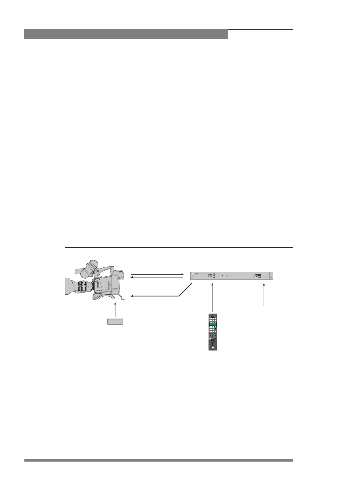
1.4.1 Digilink system SDI coax configuration
A camera head with an LDK 5481/00 adapter can be connected to the LDK 4700/00 base unit
using two coax SDI cables. The maximum length of cable that can be used is 250m (820 ft).
High quality coax cable should be used (for example, Belden 1694A). The DC power supply
for the camera is supplied directly to the adapter by an optional local power supply or by the
base unit (using a DC power cable).
Figure 1-1. DigiLink system SDI coax connection
LDK 5481/00
Soft Focus
er
Pow
on
SD Camera head
DigiLink Adapter
1
A
Clear
Clear
ND1/4
Star 4P
2
B
ND1/16
Star 6P
3
C
Smart
card
ND1/64
4
D
P wel
optional LDK 5901
DC power supply
2x coax cable
max. length 250m. (820ft.)
optional DC power cable
OCP 400/10
LDK 4700/10 DigiLink Base Unit
Ready On-air
RS-422 with
powerline LDK8121/xx
max. length 25m. (82ft.)
mains power
v4.0
Page 7
LDK 5481 + LDK 4700 User’s Guide | DigiLink system 1-3
When a DC power cable is used to power the camera from the base unit, refer to section
3.5.13 for the pin layout of the DC connector. The maximum length of the cable depends on
the type of cable and the power used by the camera. The table below is an indication of the
cable lengths that can be used.
Table 1-2. cable length indication for DC power cable
☞
listed cable
type
AWG 20 0.75 mm
AWG 18 1.0 mm
AWG 16 1.3 mm
Note
cable cross
section
2
2
2
max. length
(3A/40W)
50 m 30 m
75 m 45 m
125 m 75 m
Always use a power cable from the portable power cables category, type W, G, G-GC or PPE.
The cable must be listed in accordance with NEC article 400 of ANSI/NFPA70.
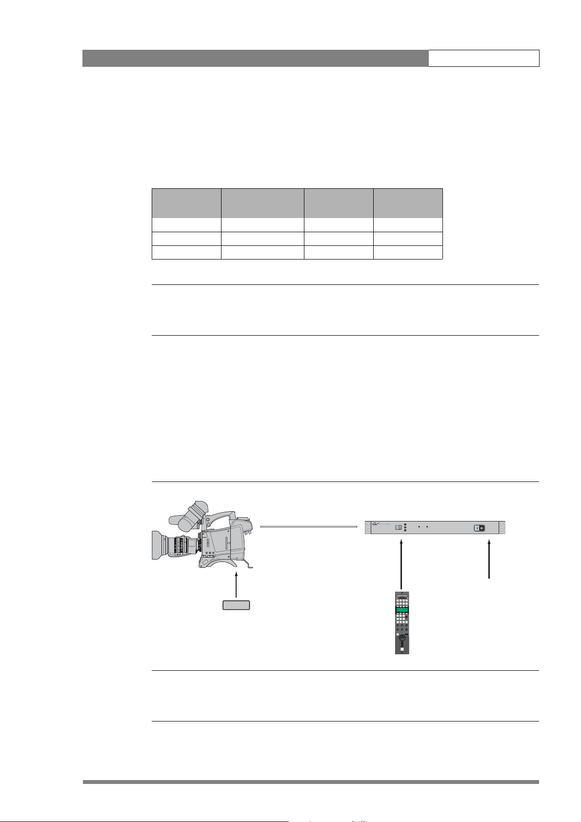
1.4.2 DigiLink system multicore configuration
A camera head with an LDK 5481/00 adapter can be connected to the LDK 4700/10 base unit
using multicore cable. The maximum length of cable that can be used is 75 m (250 ft). The
base unit can supply power for the camera via the multicore cable. The power consumption
of the camera may reduce the maximum length of cable that can be used, so alternatively, the
power for the camera can be supplied directly to the adapter from the optional LDK 5901
power supply.
Figure 1-3. DigiLink system multicore connection
max. length
(5A/60W)
LDK 5481/00
☞
SD Camera head
Note
DigiLink Adapter
1
A
Clear
Clear
ND1/4
Star 4P
2
B
ND1/16
Star 6P
3
C
Smart
card
ND1/64
Soft Focus
4
D
P wel
Power
on
optional LDK 5901
DC power supply
26-pin CCZ-A Multicore cable
max. length 75m (250ft.)
OCP 400/10
LDK 4700/00 DigiLink Base Unit
Ready On-air
RS-422 with
powerline LDK8121/xx
max. length 25m. (82ft.)
mains power
Always use a listed 26-pin CCZ-A multicore cable compliant with EBU N21 (for example, Draka
multicore camera cable type 755-2 PVC.)
v4.0
Page 8
LDK 5481 + LDK 4700 User’s Guide | DigiLink system 1-4
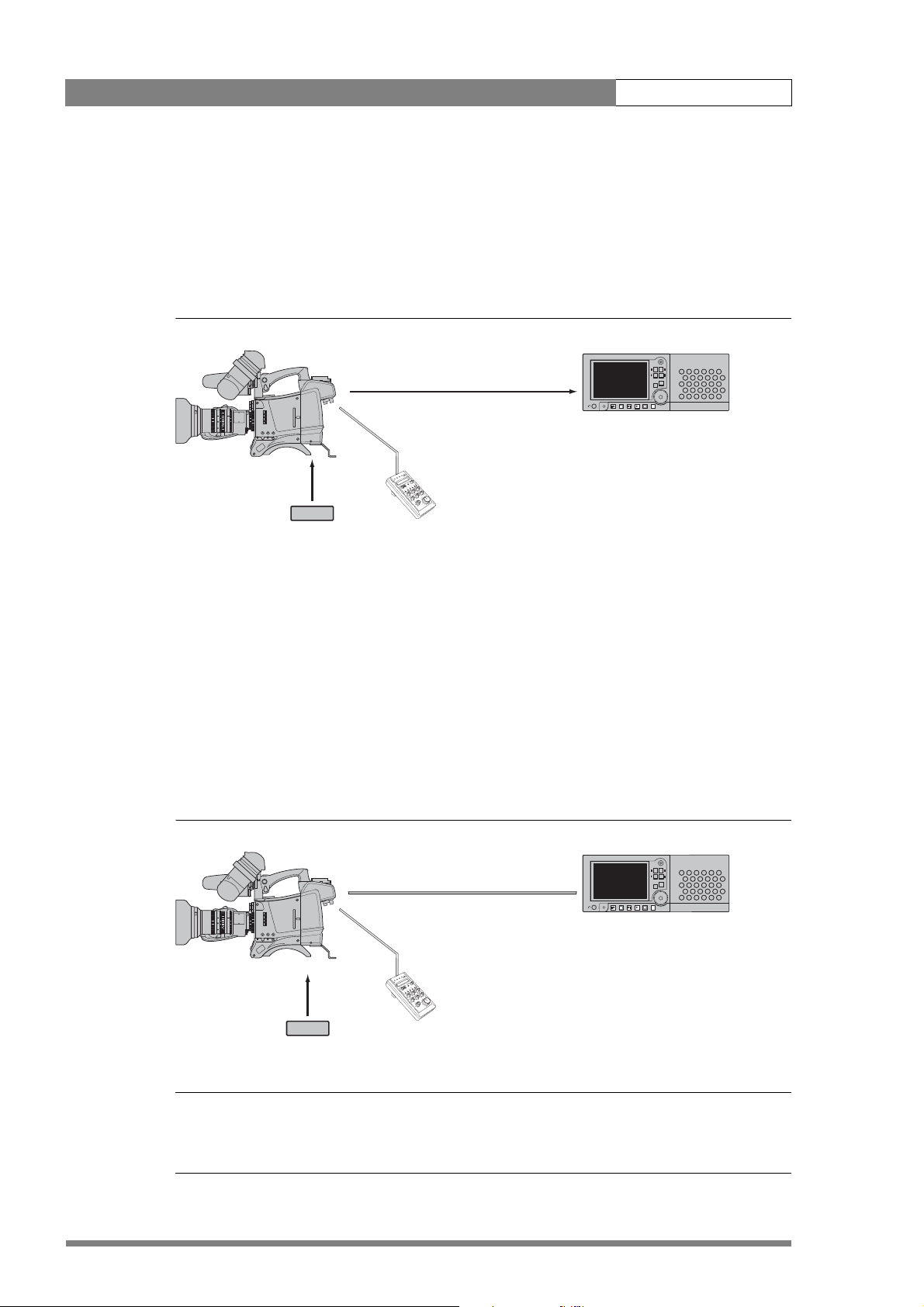
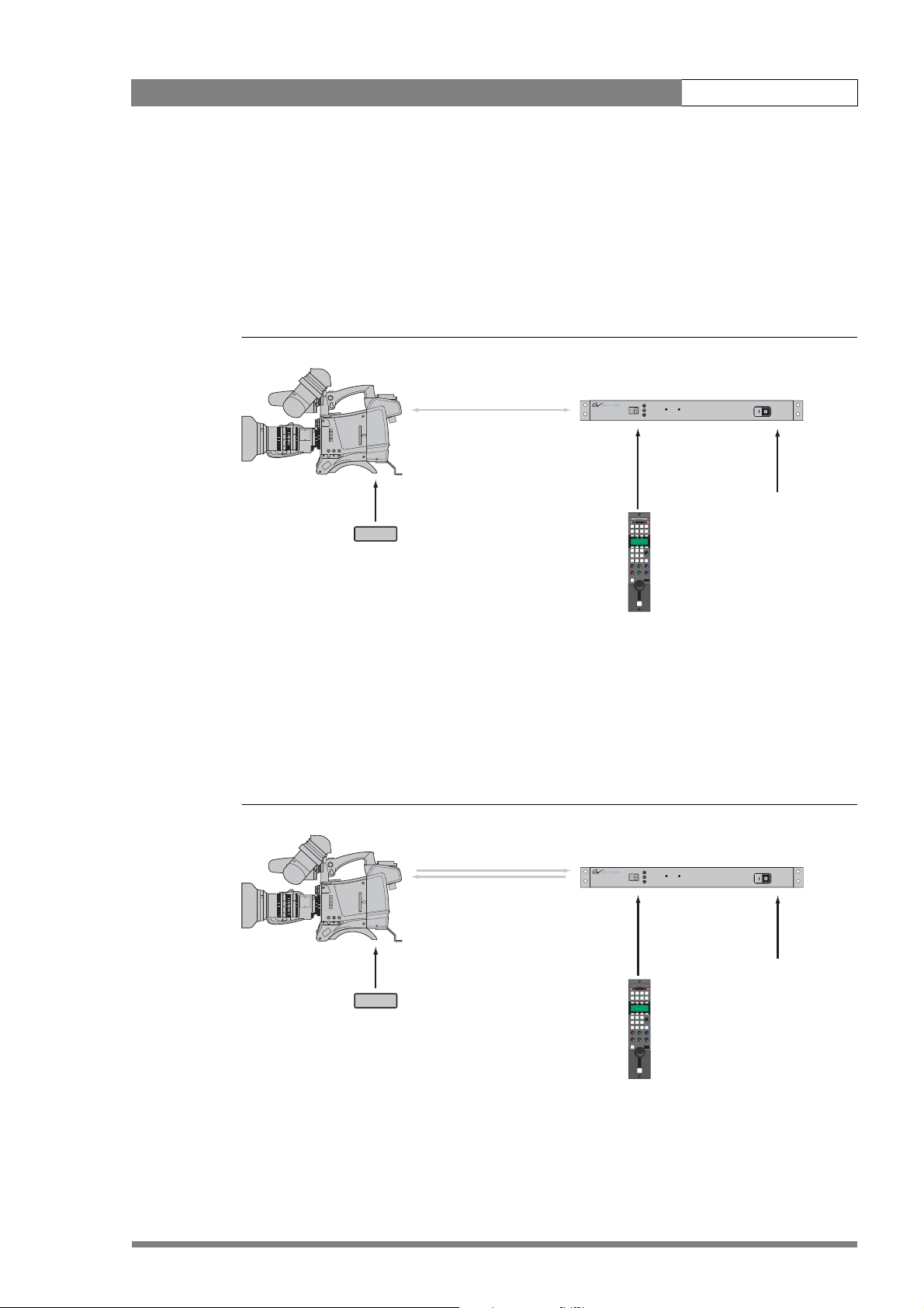
1.4.3 Stand alone SDI coax configuration
A camera head with an LDK 5481/00 adapter can be connected to a recorder unit using an
SDI coax cable. Only the SDI signal is passed via the coax cable. The maximum length of cable
that can be used is 300 m (1000 ft). High quality coax cable should be used (for example,
Belden 1694A). The DC power supply for the camera is supplied directly to the adapter.
Figure 1-4. Stand alone SDI coax configuration
LDK 5481/00
DigiLink Adapter
1
A
Clear
Clear
ND1/4
Star 4P
2
B
ND1/16
Star 6P
3
C
Smart
card
ND1/64
Soft Focus
4
D
el
P w
r
e
w
o
n
P
o
e
/r
SD Camera head
optional LDK 5901
DC power supply
d
n
e
p
a
T
LCP 100
t
at
B
!
l
e
n
f
a
f
p
l
n/o
ro
t
o
n
R
o
c
l
VT
a
c
o
l
0
0
1
P
n
LC
tio
unc
F
te
ra
Ope
stop
start/
TR
V
n
i
a
G
k
c
a
l
B
1.4.4 Stand alone multicore configuration
A camera head with an LDK 5481/00 adapter can be connected to a recorder using a
multicore cable. Power can be supplied by the recorder via the multicore cable or directly to
the adapter itself. To avoid degradation in the video signal, the maximum cable length is
restricted to 5 m (17 ft) when the component outputs are used in the recorder.
If the recorder uses the SDI signals, then the maximum length of cable depends on the ability
of the recorder unit to supply sufficient power to the camera. When the adapter is powered
directly the maximum length is 100 m (330 ft). With minimum power supplied from the
recorder unit the maximum length is 25 m (80 ft).
Video recorder
SDI coax cable
Figure 1-5. Stand alone multicore configuration
Video recorder
☞
SD Camera head
Note
LDK 5481/00
DigiLink Adapter
1
A
Clear
Clear
ND1/4
Star 4P
2
B
ND1/16
Star 6P
3
C
Smart
card
ND1/64
Soft Focus
4
D
l
e
w
P
r
e
w
o
n
P
o
optional LDK 5901
DC power supply
26-pin CCZ-A Multicore cable
/re
d
n
e
p
a
T
LCP 100
tt
a
B
!
l
e
n
f
a
p
/of
l
n
ro
t
o
n
R
o
c
T
l
V
a
c
o
l
0
0
1
P
LC
Function
erate
p
O
VTR start/stop
n
i
a
G
k
c
a
l
B
Always use a listed 26-pin CCZ-A multicore cable compliant with EBU N21 (for example, Draka
multicore camera cable type 755-2 PVC)
v4.0
Page 9
LDK 5481 + LDK 4700 User’s Guide | DigiLink system 1-5
1.4.5 DigiLink system hybrid fiber configuration
A camera head with an LDK 5481/20 fiber adapter can be connected to the LDK 4700/20
base unit using a hybrid fiber cable that carries both signal and power. The maximum cable
length that can be used is 100 m (330 ft). The power consumption of the camera may reduce
the maximum length of cable that can be used, so alternatively, the power for the camera can
be supplied directly to the adapter from the optional LDK 5901 power supply.
Figure 1-6. DigiLink system hybrid fiber connection
LDK 5481/20
SD camera head
1
A
Clear
Clear
2
B
ND1/4
Star 4P
3
C
ND1/16
Star 6P
4
D
ND1/64
Soft Focus
P wel
n
Power
o
DigiLink adapter
Smart
card
Hybrid fiber cable
max. 100 m (330 ft)
LDK 4700/20 DigiLink Base unit
Ready On-air
RS-422 with
powerline LDK8121/xx
max. 25 m (82 ft)
Mains power
optional LDK 5901
DC power supply
1.4.6 DigiLink system dual fiber configuration
A camera head with an LDK 5481/20 fiber adapter can be connected to the LDK 4700/20
base unit using a dual fiber cable. The maximum cable length that can be used is 5,000 m
(16,400 ft). The camera adapter must be powered locally by the optional LDK 5901 DC power
supply.
Figure 1-7. DigiLink system dual fiber connection
LDK 5481/20
LDK 5481/20
DigiLink adapter
DigiLink adapter
1
A
1
A
Clear
Clear
Clear
SD camera head
SD camera head
Clear
2
B
2
B
ND1/4
Star 4P
ND1/4
Star 4P
3
C
3
C
ND1/16
Star 6P
ND1/16
Star 6P
Smart
Smart
card
card
4
D
4
D
ND1/64
Soft Focus
ND1/64
Soft Focus
l
e
w
P wel
P
er
er
Pow
Pow
on
on
Hybrid fiber cable
Dual fiber cable
max. 100 m (330 ft)
max. 5,000 m (16,400 ft)
OCP 400/10
LDK 4700/20 DigiLink Base unit
LDK 4700/20 DigiLink Base unit
Ready On-air
Ready On-air
RS-422 with
RS-422 with
powerline LDK8121/xx
powerline LDK8121/xx
max. 25 m (82 ft)
max. 25 m (82 ft)
Mains power
Mains power
v4.0
optional LDK 5901
optional LDK 5901
DC power supply
DC power supply
OCP 400/10
OCP 400/10
Page 10
LDK 5481 + LDK 4700 User’s Guide | DigiLink system 1-6
1.5 Intercom
An intercom channel connects the base unit to the camera operator's headset. The operator's
intercom microphone signal is sent to the base unit. The headset can be connected to the 5
pin XLR headset connector at the back of the DigiLink adapter. For the connector and detailed
pin descriptions refer to chapter 2.7.7.
A conversation is started when the camera operator presses the VTR Start button at the front
of the camera or the VTR button on the lens. The function and behaviour of this button can be
defined in the INSTALL menu of the camera. Refer to the camera’s user’s guide.
The volume of the headset earmuffs can be adjusted by turning the audio volume knob at the
front (right side) of the camera.
Intercom configuration
The sidetone volume level (feedback signal from the microphone to the earmuffs) can be
adjusted withthe INSTALL/INTERCOM/SIDETONE function n the camera (available only when
a 4-wire connection is used).
Depending on the type of microphone the following items can be set in the INSTALL/
INTERCOM
menu in the camera:
• Microphone gain level (0 or +40 dB) with the CAM.MIC_GAIN function;
• Microphone power can be switched on or off with the CAM.MIC_POWER function.
Both 2-wire and 4-wire intercom connections can be used. On the base unit, set the setup
switch S1 in the Off-position when a 4-wire connection is used and set it in the On-position
when a 2-wire connection is used. Refer to chapter 3.5.2 for the description of the setup
switch.
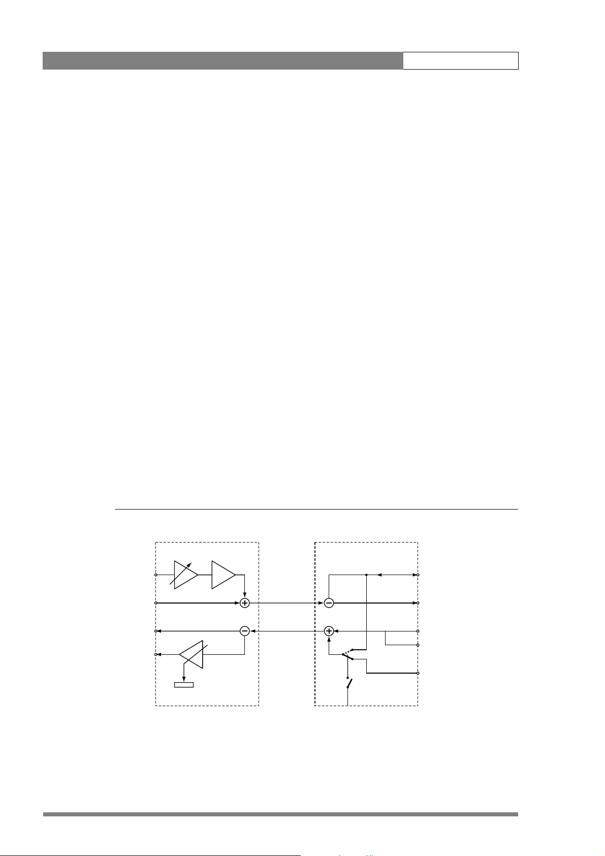
The following figure shows an overview of the routing of the intercom system. For the
connector and detailed pin descriptions refer to chapter 3.4.
Figure 1-8. Schematic overview of the intercom routing
DigiLink adapter DigiLink base unit
0 / 40 dB
Mic in
-24/-64 dBu
Cam Video
EXT/TP video
Out
0 dBu
front volume
Cam SDI OUT
Cam SDI IN
2 w.
4 w.
S1 Off = 4-wire
S1 On = 2-wire
PROD out (4-wire)
PROD in/out (2-wire)
0 dBu
pin 1,9 return
SDI
EXT
TP
PROD in (4-wire)
0 dBu
pin 5, 13 return
v4.0
Page 11

LDK 5481 + LDK 4700 User’s Guide | DigiLink Adapter 2-1
Chapter 2
DigiLink Adapter
Important information (English)
Read this information carefully before installing or servicing this equipment and retain them for
future reference. Read and comply with the warning and caution notices that appear in the
manual.
Any changes or modifications not expressly approved in this manual could void your authority
to operate this equipment.
Safety Summary
This informaton is intended as a guide for trained and qualified personnel who are aware of
the dangers involved in handling potentially hazardous electrical/electronic equipment. It is
not intended to contain a complete list of all safety precautions which should be observed by
personnel in using this or other electronic equipment.
The installation of this equipment involves risks both to personnel and equipment and must
be performed only by qualified personnel exercising due care.
During installation and operation of this equipment, local building safety and fire protection
standards must be observed.
Whenever it is likely that safe operation is impaired, the apparatus must be made inoperative
and secured against any unintended operation. The appropriate servicing authority must then
be informed. For example, safety is likely to be impaired if the apparatus fails to perform the
intended function or shows visible damage.
Warnings
Warnings indicate danger that requires correct procedures or practices to prevent death or
injury to personnel.
v4.0
• Do not modify this equipment.
• Installation of this equipment must only be performed by qualified personnel.
• Do not use any accessories other than those recommended by the manufacturer.
• In case of an emergency ensure that the power is disconnected.
Page 12

LDK 5481 + LDK 4700 User’s Guide | DigiLink Adapter 2-2
• There are no user servicable parts inside. Refer servicing to qualified personnel only or
contact your local Grass Valley representative.
Cautions
Cautions indicate procedures or practices that should be followed to prevent damage or
destruction to equipment or property.
• Always switch off the camera before changing the power supply.
• Be extremely careful with the connectors between the camera head and the adapter. Do
not allow the guide pins to damage the pins of the connector. Follow these steps in the
order given. Tightening the screws in the wrong order could result in mechanical damage
to the camera. Loosening the screws in the wrong order could result in mechanical
damage to the camera.
• To prevent risk of overheating, ventilate the units correctly.
• Do not subject the unit to severe shocks or vibration.
• Do not expose the unit to extremes of temperature.
• Do not leave the unit in direct sunlight or close to heating appliances for extended periods.
• Avoid very damp places. If the environment is wet or damp a rain cover must be used to
protect the unit.
Wichtige Hinweise (Deutsch)
Lesen Sie bitte diese Hinweise genau bevor Sie diese Apparatur installieren und erhalten Sie
Sie für künftiges Nachslagen. Beachten und Lesen Sie alle mit “Achtung” und “Vorsicht”
gekennzeichneten Warnhinweise.
Änderungen haben zur Folge, dass die Garantie ungültig wird und der Benutzer für etwaige
durch die veränderte Ausrüstung verursachte Störungen haftbar gemacht werden könnte.
Sicherheit (Zusammenfassung)
Diese Informationen sind als Leitfaden für qualifiziertes Fachpersonal gedacht, das die
Gefahren beim Umgang mit potenziell gefährlicher elektrischer/elektronischer Ausrüstung
kennt. Es handelt sich dabei nicht um eine vollständige Zusammenstellung aller
Sicherheitsvorkehrungen, die beim Gebrauch dieser oder anderer elektronischer Geräte zu
beachten sind.
Die Montage, Wartung und Instandsetzung dieser Ausrüstung ist mit Risiken für Personal und
Ausrüstung verbunden und darf nur von qualifiziertem Personal vorgenommen werden, wobei
mit der nötigen Sorgfalt vorzugehen ist.
v4.0
Mit der Montage, Bedienung, Instandhaltung oder Instandsetzung dieser Ausrüstung
betrauten Personen wird dringend geraten, sich mit der Theorie und Praxis der Ersten Hilfe
vertraut zu machen.
Beim Einbau und Betrieb dieser Ausrüstung müssen die örtlichen Gebäudesicherheits- und
Brandschutzvorschriften beachtet werden. Vor dem Anschluss der Ausrüstung an die
Stromversorgung der Anlage muss überprüft werden, ob der Schutzleiter intakt ist.
Page 13

LDK 5481 + LDK 4700 User’s Guide | DigiLink Adapter 2-3
Wenn eine Beeinträchtigung des sicheren Betriebs wahrscheinlich ist, muss das Gerät außer
Betrieb gesetzt und gegen ungewollten Betrieb gesichert werden. Dann muss der zuständige
Kundendienst benachrichtigt werden. Eine Beeinträchtigung der Sicherheit ist zum Beispiel
dann wahrscheinlich, wenn das Gerät nicht wie vorgesehen funktioniert oder einen sichtbaren
Schaden aufweist.
Vorsicht!
Mit “Vorsicht” wird auf eine Gefahr hingewiesen, die korrekte Arbeits- oder Verfahrensweisen
erfordert, um Tod oder Verletzung zu verhindern.
• An dieser Ausrüstung dürfen keine Änderungen vorgenommen werden;
• Die Montage dieser Ausrüstung darf nur von Fachpersonal vorgenommen werden;
• Es sollen nur von den Hersteller empfohlene Zubehöre verwendet werden;
• Bei Eintreten eines Notfalls unbedingt die Stromzufuhr abschalten;
• Dieses Produkt enthält keine Anwenderteile. Reparatur und Wartung nur von
qualifiziertem Fachpersonal vornehmen lassen oder nehmen Sie Kontakt auf mit Ihrem
Grass Valley Vertretene;
Achtung!
Mit “Achtung” werden Arbeitsanweisungen gekennzeichnet, die zu befolgen sind, um eine
Beschädigung oder Zerstörung der Ausrüstung bzw. von Eigentum zu verhindern.
• Die Kamera vor dem Wechsel der Stromversorgung immer ausschalten;
• Stecker zwischen Kamerakopf und Adapter mit äußerster Vorsicht handhaben. Darauf
achten, dass die Steckerstifte nicht durch die Führungsstifte beschädigt werden.
• Um einer Überhitzungsgefahr vorzubeugen, ist das Produkt korrekt zu belüften;
• Dieses Produkt darf nicht an extremen stöße oder Zittern ausgesetzt werden;
• Dieses Produkt darf nicht an extremen Temperaturen ausgesetzt werden;
• Nicht langfristig in direktem Sonnenlicht oder in der Nähe von Heizgeräte zurücklassen.
• Vermeide feuchtigen Plätze. Wenn die Umgebung nass oder feucht ist, muss ein
Regenüberzug verwendet werden um das Gerät zu schützen.
v4.0
Page 14
LDK 5481 + LDK 4700 User’s Guide | DigiLink Adapter 2-4
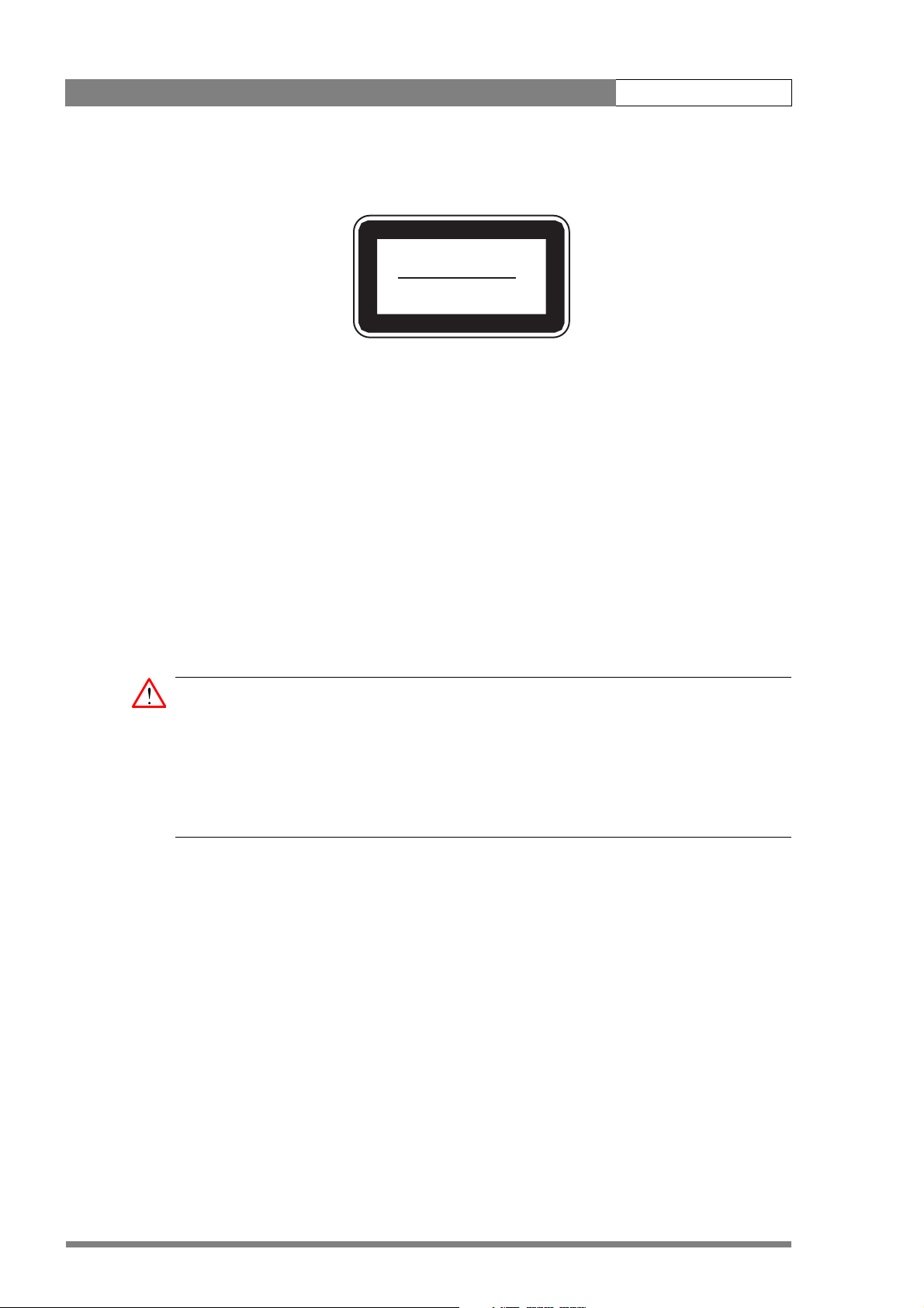
Fiber optic transmission units
CLASS 1
LASER PRODUCT
LASER KLASSE 1
PRODUKT
A yellow coloured CLASS 1 LASER PRODUCT label is located on top of the fiber optic
connector on the rear panel of the adapter.
Laser safety statement (Europe)
Fiber optic transmission units are classified as a “CLASS 1 Laser Product” according to
EN 60825-1, Safety of Laser products. Class 1 laser products are considered safe and do not
result in biological hazard if used according to the instructions.
Laser safety statement (US)
Fiber optic transmission units are classified as a “CLASS 1 Laser Product” according to
21CFR 1040.10 of the US Food and Drug Administration (FDA) Center for Devices and
Radiological Health.
WARNING
Use of controls, adjustments or performance of procedures other than those specified
herein may result in hazardous radiation exposure.
To ensure proper use of this product, please read this instruction manual carefully and
retain for future reference. Should the unit ever require maintenance, contact an
authorized service location.
Fiber optic cable precautions
Fiber optic cables and connectors are easily damaged; take the following percautions into
account:
• Do not bend the cable beyond the minimum bend range specified for the cable.
• Avoid kinks or sharp bends in the cable.
v4.0
• Avoid subjecting the cable to a high tension force.
• Do not twist the cable when connecting it to equipment.
• Insert connectors straight and fully into their corresponding sockets.
• In fiber optic cable systems always put the dust caps on cable and panel connectors
immediately after disconnecting a cable. Keep the dust caps clean.
Page 15
LDK 5481 + LDK 4700 User’s Guide | DigiLink Adapter 2-5
2.1 Specifications
The DigiLink camera adapter is available in two versions:
• The LDK 5481/00 version has a 26-pin multicore connector and two SDI coax connectors
to connect to an LDK 4700/00 or LDK 4700/10 base unit;
• The LDK 5481/20 version has a hybrid fiber connector to connect to the LDK 4700/20
DigiLink fiber adapter.
When ordering, you specify the version you require.
Item Valu e
Power requirements 12 VDC
Power consumption typical 12 W
Operating temperatures -20 to +45°C (-4 to +113°F)
Storage temperatures -20 to +60°C (-4 to +140°F)
Weight (approx.) 1.5 kg (3.3 lbs)
Dimensions 105 mm (L) x 120 mm (W) x 225 mm (H) mm without
handgrip
Power input 12 VDC XLR-4 male (or multicore cable)
Power output 12 VDC 1.5A; 4-pin Hirose
CVBS out (VF/EXT/TP) 1 Vpp; 75 Ohm; BNC
Viewfinder output (CVBS/EXT/TP) 1 Vpp; 75 Ohm; BNC
LCP connector for connecting an LCP 100 local control panel;
12-pin Hirose
LDK 5481/00 version (multicore/coax)
Multicore connection 26-pin EBU N21 multicore connector
SDI Video output SMPTE 259M, 0.8 Vpp, 270Mb/s; 75 Ohm; BNC
SDI Video input SMPTE 259M, 0.8 Vpp, 270Mb/s; 75 Ohm; BNC
LDK 5481/20 version (fiber version)
DigiLink connection Neutrik hybrid fiber optical connecotor
v4.0
Page 16

LDK 5481 + LDK 4700 User’s Guide | DigiLink Adapter 2-6
2.2 Dimensions
Figure 2-1. LDK 5481 DigiLink adapter dimension sketch
2.3 Compatibility
Before using the LDK 5481 DigiLink adapter you must ensure that it is compatible with your
camera head. Camera heads with software version v13.0 and higher are fully compatible and
do not need to be upgraded. Camera heads with software below this version must be
updated.
Older camera heads with data board no. 3922 406 84271 or LDK 100 cameras built before 2001 need to be
upgraded. For more information on upgrading your camera contact your Grass Valley service representative.
v4.0
Page 17

LDK 5481 + LDK 4700 User’s Guide | DigiLink Adapter 2-7
2.4 Controls
Figure 2-2. LDK 5481 adapter controls
2
1
DC out LCP CVBS VF
1. Power source selection switch
2. Power on indicator (green)
3. Tally indicators (red)
4. Circuit breaker button (fuse)
3
4
2.4.1 Powering the camera
The power supply for the camera and the adapter (+12 Vdc) is normally supplied either via
the multicore connector or via the DC IN socket. Set the power source selection switch (1) to
the position that corresponds to your chosen method:
• LOC: Powered via DC IN socket
• REM:Powered via multicore
The power on indicator (2) lights when power is supplied and the camera power switch is On.
If excessive current flows in the camera or adapter, the circuit breaker (4) trips and shuts off
power to all the units. If this happens, check the units for faults and if necessary take
corrective action before pressing the circuit breaker button to reset the power.
v4.0
Page 18

LDK 5481 + LDK 4700 User’s Guide | DigiLink Adapter 2-8
2.5 Attaching the LDK 5481 adapter to a camera head
The LDK 5481 adapter is shorter than a standard adapter. Before attaching the LDK 5481
adapter to a camera, the carrying handle must be re-positioned on the camera head using the
mounting bracket supplied with the adapter.
To re-position the carrying handle for a short adapter, proceed as follows:
1. Remove the viewfinder and any other adapter attached to the camera.
2. Unscrew and remove the two screws that attach the front of the carrying handle to the
camera. (For the LDK 500: tilt the carrying handle backwards and use your fingertips to
gently unplug the flat cable that connects the zoom control to the connector inside the
camera body.)
Note
☞
The digital zoom control of the LDK 500 cannot be used in combination with the LDK 5481
adapter. An optional analogue zoom control LDK 6113 can be used.
3. Remove the carrying handle from the camera.
4. Use the supplied screws and washers to attach the mounting bracket to the top of the
camera. (Use the screw holes where the handle was previously attached.)
Figure 2-1. Carrying handle replacement
(2x)
1
A
Clear
Clear
2
ND1/4
B
Star 4P
3
ND1/16
C
Star 6P
4
ND1/64
D
Soft Focus
VTR
Ext.
Std.
Save
Iris
File
r
e
w
o
P
f
f
O
r
e
w
o
n
P
O
Smart
card
5. For LDK 500: fold the flat cable away into the hollow part of the carrying handle.
6. Place the carrying handle into the recess at the front of the mounting plate and use the
two original screws to secure it in place.
7. Attach the LDK 5481 adapter to the camera (refer to section “Attaching an adapter” in the
User’s Guide of your camera for further instructions).
(2x)
(2x)
1
A
Clear
Clear
2
B
ND1/4
Star 4P
3
C
ND1/16
Star 6P
4
D
ND1/64
Soft Focus
VTR
Ext.
Std.
Save
Iris
File
Power
Off
Power
On
Smart
card
1
A
Clear
Clear
2
B
ND1/4
Star 4P
3
C
ND1/16
Star 6P
4
D
ND1/64
Soft Focus
VTR
Ext.
Std.
Save
Iris
File
Power
Off
Power
on
Smart
card
v4.0
Page 19

LDK 5481 + LDK 4700 User’s Guide | DigiLink Adapter 2-9
2.6 Mounting a script board
To attach the optional script board (LDK 6985/21) to the adapter use the special bracket and
screws delivered with the script board. To attach the bracket to the adapter, proceed as
follows:
1. Unscrew and remove the four screws attaching the viewfinder holder to the top of the
adapter.
2. Place the viewfinder holder on top of the script board bracket and align the screw holes.
3. Using the four long screws provided, attach the holder and bracket to the top of the
adapter.
4. The script board can now be mounted onto the bracket.
Figure 2-3. Script board accessory
viewfinder
holder
script board
holder bracket
v4.0
Page 20

LDK 5481 + LDK 4700 User’s Guide | DigiLink Adapter 2-10
2.7 Adapter connectors
Figure 2-4. DigiLink adapter connector locations
LDK 5481/20LDK 5481/00
Script light
output
SCRIPTLIGHT
DC power
supply input
POWER
LOC/REM
DC IN
FUSE
Multicore
connector
SDI
video out
SDI
SDI
video in
DC out LCP CVBS VF
BA
Hybrid fiber
connector
Script light
output
POWER
SCRIPTLIGHT
LOC/REM
DC IN
FUSE
DC power
supply input
Headset
connector
SDI
video out
SDI
SDI
video in
v4.0
DC power
output
LCP
connector
CVBS
output
VF
output
Page 21

LDK 5481 + LDK 4700 User’s Guide | DigiLink Adapter 2-11
2.7.1 SDI video output connector
Figure 2-5. SDI video output connector
This BNC connector supplies an SDI video output signal
(Y/Cr/Cb 4:2:2) that also includes embedded audio,
intercom and private data signals.
BNC connector: panel view (X8)
2.7.2 SDI video input connector
Figure 2-6. SDI video input connector
BNC connector: panel view (X9)
This BNC connector receives an SDI video input from
the base unit.
Reference, teleprompter and external video signals are
embedded in the stream together with intercom,
control and private data signals.
v4.0
Page 22

LDK 5481 + LDK 4700 User’s Guide | DigiLink Adapter 2-12
2.7.3 Multicore connector
Figure 2-7. Multicore connector
A.+ Battery from VTR (+10.7 to +17V)
B.- Battery Ground
A
B
4
5
6
11
17
26-pin male; panel view
Panel part number: (X6) 3922 040 02571
This multicore connector can be used to
connect either a recorder or a base unit
(LDK 4700/10).
When connected to a recorder it provides the
video outputs, control signals and the camera
microphone signal. DC power can also be
supplied to the camera via this connector.
The connector accepts a playback video signal
for display in the viewfinder. The start/stop
control signal for an external recorder is also
passed via this connector.
9
10
15
16
21
22
1
2
3
7
8
12
13
14
18
19
20
23
24
1. SDI
2. SDI Return
3. Y Return
4. Y
5. Pr: NTSC 700mV 75% saturated colour bar
Cr: PAL 525mV (EBU N10)
6. Pr/Cr Return
7. Pb: NTSC 700mV 75% saturated colour bar
Cb: PAL 525mV (EBU N10)
8. Pb/Cb Return
9. Cam. Mic. X
10. Cam. Mic. Y
11. Cam. Mic. shield
12. VTR start/stop: +5V = recording; 0V = stop
13. Batt. alarm
14. Power sense
15. Record/Tally
16. Genlock Video/BB return
17. Cable shield (Camera GND to VTR GND)
18. Playback video / Ext. VF
19. Playback video return / Ext. VF return
20. VTR Save
21. Genlock Video/BB
22. Spare
23. RXD, control
24. TXD, control
v4.0
Page 23

LDK 5481 + LDK 4700 User’s Guide | DigiLink Adapter 2-13
2.7.4 Hybrid fiber connector
Figure 2-8. Hybrid fiber connector
A Fiber IN
B Fiber OUT
BA
4
Neutrik OpticalCon® Hybrid Fiber connector
(NO2-4FD-1-R)
32
1
1. Power GND
2. Power GND sense
3. Power + sense
4. Poweer +
2.7.5 Video signal (VF) output connector
Figure 2-9. Video signal (VF) output connector
This BNC socket provides a 1.0 Vpp analog output video
signal. This signal can be assigned in the
menu of the camera. Either the VF, CVBS, EXT. or TP
signal can be selected.
By default the viewfinder signal is output. Markers and
menus similar to those in the viewfinder can be
superimposed on this signal.
BNC connector: panel view
2.7.6 Video signal (CVBS) output connector
Figure 2-10. Video signal (CVBS) output connector
This BNC socket provides a 1.0 Vpp analog output video
signal. This signal can be assigned in the
menu of the camera. Either the VF, CVBS, EXT. or TP
signal can be selected.
INSTALL
INSTALL
v4.0
By default the CVBS signal is output for viewing.
BNC connector: panel view
Page 24

LDK 5481 + LDK 4700 User’s Guide | DigiLink Adapter 2-14
2.7.7 Intercom headset connector
Figure 2-11. XLR intercom headset connector
1. Microphone return
2. Microphone
1
2
3
4
5
XLR 5-pin female; panel view (X11)
3. Telephone return
4. Telephone left
5. Telephone right
Microphone level: -64 dBu / -24 dBu switchable
Microphone impedance: >600 Ohm
Telephone level: +6 dBu nominal
Telephone output impedance: <50 Ohm
2.7.8 LCP / Fiber power connector
Figure 2-12. LCP connector
19
8
Hirose 12-pin female; panel view
Panel part number: (X5) 2422 026 04355
210
311127
46
5
This connector is used to connect an LCP control panel
(LDK 5201) to the camera.
1. -
2. RS-232 RXD
3. RS-232 TXD
4. Private data IN (Camera to base unit)
5. GND
6. -
7. Private data OUT (base unit to Camera)
8. -
9. +Batt
10. SDA
11. SCL
12. Housing
v4.0
Page 25

LDK 5481 + LDK 4700 User’s Guide | DigiLink Adapter 2-15
2.7.9 DC power output socket
Figure 2-13. DC power and tally output connector
1. Power ground
2. On air (+5V, 100 Ohm)
3. Housing
1
4
Hirose 4-pin female; panel view
Panel part number: (X3) 2422 026 04675
2
3
4. +12 Vdc (max. 18W)
Shield of cable directly to the connector housing.
The socket provides access to an internal tally switch.
When the camera is on-air, the contact of the internal
relay is closed.
2.7.10 DC power input socket
Caution
The input voltage must not exceed +17 Vdc.
Figure 2-14. DC power input connector
1
23
XLR 4-pin male: panel view (X7)
4
1. Power ground
2. -Batt sense
3. +Batt sense
4. +10.5 Vdc . . . +17 Vdc
This socket accepts a DC voltage of 12V nominal.
Maximum power consumption 60W.
v4.0
Page 26

LDK 5481 + LDK 4700 User’s Guide | DigiLink Adapter 2-16
2.7.11 Script light power supply socket
Figure 2-15. Script light power supply output connector
1. +12 Vdc (maximum dissipation 3W)
2. Power return
3. Shield
1
2
3
Fischer 3-pin female: panel view
Panel connector number: (X4) 3922 040 02881
v4.0
Page 27

LDK 5481 + LDK 4700 User’s Guide | DigiLink Adapter 2-17
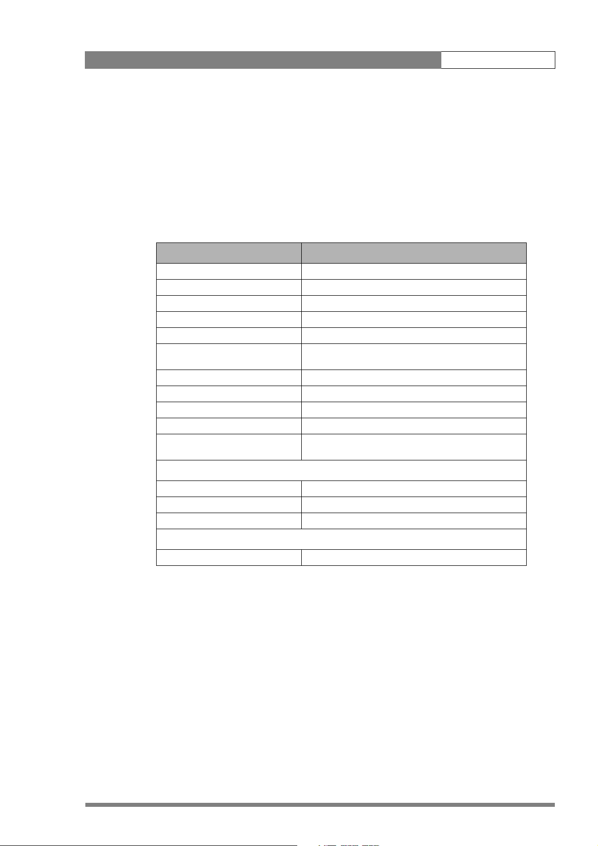
2.8 Install menu
The functions shown in the table below appear in the INSTALL menu of the camera head
when an LDK 5481 adapter is attached. Refer to the User’s Guide of the camera head for more
information on accessing this menu.
Main menu items Purpose
Disable Camera on/off
IR receiver on/off
OnAir Lamp on/off
Intercom set intercom values
Audio set gain and filter
Timing set subcarrier and h-phase
Notch on/off
Aspect ratio select aspect ratio values
Exposure set lighting and clear scan values
Gain preset set gain preset values
Quick Smart Touch on/off
Buttons assign functions to buttons
Video output assign YCrCb or RGB to VTR output
CVBS output assign CVBS, EXT, TP or VF to CVBS output
VF output assign CVBS, EXT, TP or VF to VF output
v4.0
Page 28

LDK 5481 + LDK 4700 User’s Guide | DigiLink Adapter 2-18
v4.0
Page 29

LDK 5481 + LDK 4700 User’s Guide | Base unit 3-1
Chapter 3
Base unit
Important information (English)
Read this information carefully before installing this equipment and retain them for future
reference. Read and comply with the warning and caution notices that appear in the manual.
Any changes or modifications not expressly approved in this manual could void your authority
to operate this equipment.
Safety Summary
This informaton is intended as a guide for trained and qualified personnel who are aware
of the dangers involved in handling potentially hazardous electrical/electronic equipment.
It is not intended to contain a complete list of all safety precautions which should be
observed by personnel in using this or other electronic equipment.
The installation of this equipment involves risks both to personnel and equipment and
must be performed only by qualified personnel exercising due care.
During installation and operation of this equipment, local building safety and fire
protection standards must be observed.
Before connecting the equipment to the power supply of the installation, the proper
functioning of the protective earth lead of the installation needs to be verified.
Whenever it is likely that safe operation is impaired, the apparatus must be made inoperative
and secured against any unintended operation. The appropriate servicing authority must then
be informed. For example, safety is likely to be impaired if the apparatus fails to perform the
intended function or shows visible damage.
Warnings
v4.0
Warnings indicate danger that requires correct procedures or practices to prevent death or
injury to personnel.
• Do not modify this equipment;
• Installation of this equipment must only be performed by qualified personnel;
• Do not use any accessories other than those recommended by the manufacturer;
• In case of an emergency ensure that the power is disconnected;
Page 30

LDK 5481 + LDK 4700 User’s Guide | Base unit 3-2
• Mount equipment so that power lead can be accessed to disconnect power;
• Any interruption of the protection conductor inside or outside the apparatus, or
disconnection of the protective earth terminal, is likely to make the apparatus dangerous.
Intentional interruption is prohibited;
• Use only fuses of the type and rating specified;
• To prevent fire or shock hazard, do not expose the unit to rain or moisture;
• There are no user servicable parts inside. Refer servicing to qualified personnel only or
contact your local Grass Valley representative;
• Observe local building safety, fire protection and electrical installation standards during
installation and operation of this equipment;
• Before connecting the equipment to the power supply of the installation, verify the proper
functioning of the protective earth lead;
• Whenever it is likely that safe operation is impaired, the apparatus must be made
inoperative and secured against any unintended operation.
Cautions
Cautions indicate procedures or practices that should be followed to prevent damage or
destruction to equipment or property.
• Do not subject the unit to severe shocks or vibration;
• Do not expose the unit to extremes of temperature;
• To prevent risk of overheating, ventilate the product correctly;
• Connect the product only to a power source with the specified voltage rating.
Wichtige Hinweise (Deutsch)
Lesen Sie bitte diese Hinweise genau bevor Sie diese Apparatur installieren und erhalten Sie
Sie für künftiges Nachslagen. Beachten und Lesen Sie alle mit “Achtung” und “Vorsicht”
gekennzeichneten Warnhinweise
Änderungen haben zur Folge, dass die Garantie ungültig wird und der Benutzer für etwaige
durch die veränderte Ausrüstung verursachte Störungen haftbar gemacht werden könnte.
Sicherheit (Zusammenfassung)
Diese Informationen sind als Leitfaden für qualifiziertes Fachpersonal gedacht, das die
Gefahren beim Umgang mit potenziell gefährlicher elektrischer/elektronischer Ausrüstung
kennt. Es handelt sich dabei nicht um eine vollständige Zusammenstellung aller
Sicherheitsvorkehrungen, die beim Gebrauch dieser oder anderer elektronischer Geräte zu
beachten sind.
v4.0
Die Montage, Wartung und Instandsetzung dieser Ausrüstung ist mit Risiken für Personal und
Ausrüstung verbunden und darf nur von qualifiziertem Personal vorgenommen werden, wobei
mit der nötigen Sorgfalt vorzugehen ist.
Page 31

LDK 5481 + LDK 4700 User’s Guide | Base unit 3-3
Mit der Montage, Bedienung, Instandhaltung oder Instandsetzung dieser Ausrüstung
betrauten Personen wird dringend geraten, sich mit der Theorie und Praxis der Ersten Hilfe
vertraut zu machen.
Beim Einbau und Betrieb dieser Ausrüstung müssen die örtlichen Gebäudesicherheits- und
Brandschutzvorschriften beachtet werden. Vor dem Anschluss der Ausrüstung an die
Stromversorgung der Anlage muss überprüft werden, ob der Schutzleiter intakt ist.
Wenn eine Beeinträchtigung des sicheren Betriebs wahrscheinlich ist, muss das Gerät außer
Betrieb gesetzt und gegen ungewollten Betrieb gesichert werden. Dann muss der zuständige
Kundendienst benachrichtigt werden. Eine Beeinträchtigung der Sicherheit ist zum Beispiel
dann wahrscheinlich, wenn das Gerät nicht wie vorgesehen funktioniert oder einen sichtbaren
Schaden aufweist.
Vorsicht!
Mit “Vorsicht” wird auf eine Gefahr hingewiesen, die korrekte Arbeits- oder Verfahrensweisen
erfordert, um Tod oder Verletzung zu verhindern.
• An dieser Ausrüstung dürfen keine Änderungen vorgenommen werden;
• Die Montage dieser Ausrüstung darf nur von Fachpersonal vorgenommen werden;
• Es sollen nur von den Hersteller empfohlene Zubehöre verwendet werden;
• Bei Eintreten eines Notfalls unbedingt die Stromzufuhr abschalten;
• Ausrüstung so montieren, daß das Netzkabel zum Abschalten der Stromzufuhr zugänglich
ist;
• Jede Unterbrechung des Schutzleiters innerhalb oder ausserhalb des Geräts oder
Trennung der Schutzleiter-anschlussklemme Könnte das Gerät fefährlich machen. Eine
absichtliche Unterbrechung ist untersagt;
• Es dürfen nur Sicherungen des vorgeschriebenen Typs und Nennwerts verwendet
werden;
• Um Feuer oder Schlaggefahr vorzubeugen, soll das Produkt nie an Regen oder Feucht
ausgesetzt werden;
• Dieses Produkt enthält keine Anwenderteile. Reparatur und Wartung nur von
qualifiziertem Fachpersonal vornehmen lassen oder nehmen Sie Kontakt auf mit Ihrem
Grass Valley Vertretene;
• Beim Einbau und Betrieb dieser Ausrüstung müssen die örtlichen Gebäudesicherheitsund Brandschutzvorschriften beachtet werden;
• Vor dem Anschluss der Ausrüstung an die Stromversorgung der Anlage muss überprüft
werden, ob der Schutzleiter intakt ist;
• Wenn eine Beeinträchtigung des sicheren Betriebs wahrscheinlich ist, muss das Gerät
außer Betrieb gesetzt und gegen ungewollten Betrieb gesichert werden.
Achtung!
v4.0
Mit “Achtung” werden Arbeitsanweisungen gekennzeichnet, die zu befolgen sind, um eine
Beschädigung oder Zerstörung der Ausrüstung bzw. von Eigentum zu verhindern.
• Dieses Produkt darf nicht an extremen stöße oder Zittern ausgesetzt werden;
• Dieses Produkt darf nicht an extremen Temperaturen ausgesetzt werden;
Page 32

LDK 5481 + LDK 4700 User’s Guide | Base unit 3-4
• Um einer Überhitzungsgefahr vorzubeugen, ist das Produkt korrekt zu belüften;
• Das Produkt darf nur an eine Stromquelle mit der vorgeschriebenen Nennspannung
angeschlossen werden.
Fiber optic transmission units
CLASS 1
LASER PRODUCT
LASER KLASSE 1
PRODUKT
A yellow coloured CLASS 1 LASER PRODUCT label is located at the back side of the unit, near
the hybrid fiber connector which is at the right side of the back panel.
Laser safety statement (Europe)
Fiber optic transmission units are classified as a “CLASS 1 Laser Product” according to
EN 60825-1, Safety of Laser products. Class 1 laser products are considered safe and do
not result in biological hazard if used according to the instructions.
Laser safety statement (US)
Fiber optic transmission units are classified as a “CLASS 1 Laser Product” according to
21CFR 1040.10 of the US Food and Drug Administration (FDA) Center for Devices and
Radiological Health.
WARNING
Use of controls, adjustments or performance of procedures other than those specified
herein may result in hazardous radiation exposure.
To ensure proper use of this product, please read this instruction manual carefully and
retain for future reference. Should the unit ever require maintenance, contact an
authorized service location.
Fiber optic cable precautions
v4.0
Fiber optic cables and connectors are easily damaged; take the following percautions into
account:
• Do not bend the cable beyond the minimum bend range specified for the cable.
• Avoid kinks or sharp bends in the cable.
• Avoid subjecting the cable to a high tension force.
Page 33

LDK 5481 + LDK 4700 User’s Guide | Base unit 3-5
h
Front
ir
• Do not twist the cable when connecting it to equipment.
• Insert connectors straight and fully into their corresponding sockets.
• In fiber optic cable systems always put the dust caps on cable and panel connectors
immediately after disconnecting a cable. Keep the dust caps clean.
Installation information
Ventilation
Cold air is taken in from the right side and expelled on the left side (see drawing).
ot air
• Do not block the air inlet or outlet;
• Clean the air inlet grill at least once a year.
Rack mounting instructions
Note that rack mounting is not mandatory for the unit. When the unit is mounted in a 19” rack
ensure that the following instructions are observed:
• The unit is supported at the rear;
• If installed in a closed or multi-rack assembly, the operating ambient temperature of the
rack environment may be greater than room ambient. Therefore, consideration should be
given to installing the equipment in an environment compatible with the maximum
ambient temperature (T
• Installation of the equipment in a rack should be such that the amount of air flow required
for safe operation of the equipement is not compromised;
) specified;
max
cold a
• Mounting of the equipment in the rack should be such that a hazardous condition is not
achieved due to uneven mechanical loading;
• Consideration should be given to the connection of the equipment to the supply circuit
and the effect that overloading of the circuits might have on overcurrent protection and
supply wiring. Appropriate consideration of equipment nameplate ratings should be used
when addressing this concern;
v4.0
Page 34

LDK 5481 + LDK 4700 User’s Guide | Base unit 3-6
• Reliable earthing of rack-mounted equipment should be maintained. Particular attention
should be given to supply connections other than direct connections to the branch circuit
(e.g. use of power strips).
Installation notices
For proper installation the following NEC articles should be noticed:
Regarding communication circuits:
– Installation of equipment (article 800.18).
Regarding radio and television equipment:
– Avoid contact with conductors of other systems (article 810.13);
– Provide extensive, separate clearance requirements for indoor and outdoor locations
(article 810.18).
Mains power supply chord
General
By default, a mains power supply chord is not shipped with the device. To connect the
LDK 4700 base unit to the mains the following power supply cord is advised: type H03 VVF or H03 VVH2-F flexible wire: 1 mm², 250V / 10A minimum or 16 AWG.
When the device is installed in one of the following countries the power chord must be
compliant to the indicated specifications and regulations indicated below:
For Denmark
Supply cord of single-phase equipment having a rated current not exceeding 10A shall be
provided with a plug according to the Heavy Current Regulations section 107-2-D1. Class I
equipment provided with socket-outlets with earth contact or which are intended to be
used in locations where protection against indirect contact is required according to the
wiring rules shall be provided with a plug in accordance with standard sheet DK 2-1a or
DK 2-5a.
For Ireland
Apparatus which is fitted with a flexible cable or cord and is designed to be connected to a
mains socket conforming to I.S. 411 by means of that flexible cable or cord and plug, shall
be fitted with a 13A plug in accordance with Statutory Instrument 525:1997 - National
Standards Authority of Ireland (section 28) (13A plugs and Conversion Adaptors for
Domestic Use) Regulations, 1997.
v4.0
For Spain
Supply cords of single-phase equipment having a rated current not exceeding:
– 10A shall be provided with a plug according to UNE 20315:1994
CLASS I EQUIPMENT provided with socket-outlets with earth contacts, or which are
intended to be used in locations where protection against indirect contact is required
Page 35

LDK 5481 + LDK 4700 User’s Guide | Base unit 3-7
according to the wiring rules, shall be provided with a plug in accordance with UNE
20315:1994
For Switzerland
Supply cords of equipment having a rated current not exceeding 10A shall be provided
vwith a plug complying with SEV 1011 or IEC 884-1 and the following dimension sheet:
– SEV 6534-2.1991 Plug Type 12: L+N+PE250V 10A
For the UK
Apparatus which is fitted with a flexible cable or a cord and is designed to be connected to a
mains socket conforming to BS 1363 by means of that flexible cable or cord and plug, shall be
fitted with a "standard plug" in accordance with Statutory Instrument 1786: 1994 - The Plugs
and Sockets etc. (Safety) Regulations 1994, unless exempted by those regulations.
Note: "Standard plug" is defined in SI 1786:1994 and essentially means an approved plug
conforming to BS 1363 or an approved conversion plug.
For the US
Listed, detachable, maximum 4.5 m (14.76 ft.) long; rated minimum 125V, 10A, type SJT or
type SVT flexible cord; one end terminates in NEMA 5-15P or 5-20P groundingtype attachment
plug, other end in appliance coupler.
Listed, detachable, maximum 4.5 m (14.76 ft.) long; rated minimum 250V, 10A, type SJT or
type SVT flexible cord; one end terminates in NEMA 6-15P or NEMA 6-20P grounding-type
attachment plug, other end in appliance coupler.
v4.0
Page 36

LDK 5481 + LDK 4700 User’s Guide | Base unit 3-8
3.1 Specifications
The base unit is available in three versions:
• The LDK 4700/00 version has a 26-pin multicore connector for use with a multicore cable
connection to the LDK 5481/10 DigiLink adapter;
• The LDK 4700/10 version has two SDI coax connectors and a DC power output to connect
to the LDK 5481/10 DigiLink or LDK 5481/20 DigiLink fiber adapter using coaxial cables;
• The LDK 4700/20 version has a hybrid fiber connector to connect to the LDK 5481/20
DigiLink fiber adapter.
When ordering, you specify the version you require.
Item Value
Power requirements 100 to 240 VAC (-10% / +6%) 50 to 60 Hz
Power consumption 200 VA
Operating temperature 0 to +45°C (32 to +113°F)
Storage temperature -20 to +60°C (-4 to +140°F)
Weight (approx.) 6 kg(13.2 lbs)
Dimensions 255 (L) x 483 (W) x 44 (H) mm (19-inch rack, 1 unit high)
Y, Pr, Pb output 1 Vpp; 75 Ohm; BNC
Audio output XLR-3 male
CVBS output (x2) 1 Vpp; 75 Ohm; BNC
Teleprompter input 1 Vpp; 75 Ohm; BNC looped-through
Reference input 1 Vpp; 75 Ohm; BNC looped-through
External video signal input 1 Vpp; 75 Ohm; BNC looped-through
Control unit D-sub 9-pin RS-422 connection for OCP 400
Intercom 2/4-wire via 15-pin male D-connector
Signalling On-air, call via 15-pin male D-connector
Auxiliary data Private data via 15-pin male D-connector
v4.0
LDK 4700/00 version (multicore)
DigiLink connection 26-pin multicore connector
LDK 4700/10 version (coax)
Coaxial SDI connectors (x2) SMPTE 259M, 0.8 Vpp, 270Mb/s; 75 Ohm; BNC
Auxiliary connection 12-pin Hirose connector
Power output DC output; XLR-4 female
LDK 4700/20 version (fiber)
DigiLink connection Neutrik hybrid fiber optical connecotor
Page 37

LDK 5481 + LDK 4700 User’s Guide | Base unit 3-9
3.2 Dimensions
Figure 3-1. DigiLink base unit dimension sketch
483 mm
465 mm
Ready On-air
44 mm
438 mm
255 mm
v4.0
Page 38

LDK 5481 + LDK 4700 User’s Guide | Base unit 3-10
3.3 Controls and indicators
Figure 3-1. DigiLink base unit controls
Ready
Display
indicator
Set-up
buttons
3.3.1 Powering the base unit
Set the power switch to the on position (I). The power on indicator in the switch lights
when the unit is powered.
3.3.2 Indicators
Table 3-2. Ready indicator
indication description
off no camera video signal detected.
green (OK) camera video signal detected.
flashing yellow no camera video signal detected and power failure or fan
flashing yellow/green camera video signal detected and power failure or fan
Ready
On-air
On-air
indicator
failure.
failure.
DigiLinK - BASE UNIT
LDK 4700
Mains
Power switch
and indicator
Table 3-3. On-Air indicator
indication description
On The camera is on air.
Off The camera is not on air.
3.3.3 Set-up items
There are five items that can be accessed via the set-up buttons:
• Camera number (CA)
• Subcarrier adjustment (SC)
• H-phase (HP)
•Status (ST)
• Menu Off (OF)
v4.0
Page 39

LDK 5481 + LDK 4700 User’s Guide | Base unit 3-11
Press the up or down button to display the required item. Press the select button
to select it. The display shows the abbreviation of the current item.
Camera Number (CA)
When CA is displayed, push the select button to enter the selection mode. Press the up or
down button to select an available camera number. Push the select button to set the new
camera number. The new camera number is shown in the display.
Subcarrier (SC)
When SC is displayed, push the select button to enter the Subcarrier adjustment mode.
Press the up or down button to shift the Subcarrier phase. If you continue to press a
button, the shift change occurs in bigger steps. Push the select button to leave the
Subcarrier adjustment mode.
H-Phase (HP)
When HP is displayed, push the select button to enter the H-Phase adjustment mode.
Press the up or down button to shift the H-Phase (this is the fine control and changes are
not visible on the display). If you press the button continuously, the shift change occurs in
bigger steps (this is the coarse control; changes are shown on the display). Push the
select button to leave the H-Phase adjustment mode.
Status (ST)
When ST is displayed, push the select button to enter the status mode. Press the up or
down button to select SO (the software status) or FI (the firmware status). Push the select
button to view the status number. Push the select button to leave the status mode.
Menu Off (OF)
This is the inactivity state of the menu
OCP control
The set-up buttons can be used to set up the base unit, however, it is more convenient to
use the OCP connected to the base unit. (Refer to the OCP user guide to find out how to
do this.)
v4.0
Page 40

LDK 5481 + LDK 4700 User’s Guide | Base unit 3-12
3.4 Connecting the studio signalling
Connect the studio signalling system to the rear of the base unit. The wiring of the panel
connector is shown below. Refer to the next chapter for the location of this connector.
Figure 3-4. Signalling / Intercom / Auxiliary connector
1. Intercom PROD Out (4-wire) or Intercom PROD In/Out
1
356
2
10 11 12
9
4
13
8
7
14
15
15-pin male D-connector; panel view
Panel part number: 2411 022 05292
A 4-wire (Off) or 2-wire (On) intercom system
is selected with rocker switch number 1.
On
Off
1 2 3 4 5 6
Side view of switches
(2-wire)
2. Call send (dry contact to pin 10)
3. n.c.
4. On Air send (dry contact to pin 12)
5. Intercom PROD In
6. Private data In
7. Private data Out
8. Housing
9. Camera microphone Out return
10. Call return
11. n.c.
12. On Air return
13. Intercom PROD In return (4-wire) or not connected (2-
wire)
14. n.c.
15. Common ground
3.4.1 Call and On-air signals
There are two connection methods for the Call and On-air signalling functions:
1. Dry contact
2. Voltage level
The connection method for the signalling functions is set by a jumper on the main board of the
base unit. Remove the upper lid of the base unit and locate jumper X317 at the bottom centre
of the board. The settings of the jumper are shown below:
Figure 3-5. Jumper settings for signalling
C2039
C2005
MP2000
R2022
R2023
R2024
R2019
C7516
IC7503
MP7502
C7513
+
19
26
IC9500
12
5
C9503
C9507
R9532
R9533
R9536
D
C
R9531
R9534
MP2004
X317
R6005
A
B
R5021
C
L1500
K6000
X312
A
dry contact voltage level
D
+
C1500
B
D
C
A
B
v4.0
Page 41

LDK 5481 + LDK 4700 User’s Guide | Base unit 3-13
Dry contact signalling
Figure 3-6. Dry contact signalling
base unit
signalling
External
signaling
dry contact
connector
Voltage level signalling
Figure 3-7. Voltage level signalling
+5 - 12 Vdc
+
External
signaling
with DC
output
voltage
base unit
signalling
connector
v4.0
Page 42

LDK 5481 + LDK 4700 User’s Guide | Base unit 3-14
3.5 DigiLink base unit connectors
Figure 3-2. DigiLink base unit connector locations
LDK 4700/00
Power
supply input
LDK 4700/10
Camera
audio
output
Audio
Audio
Signalling
Intercom
Aux.
connector
Auxiliary
RS422
RS-422
connector
Auxiliary
RS422
1 . . . 6
Setup
switches
1 . . . 6
External/
Reference/
Teleprompter
inputs
Ext Ref TP
External/Reference/
Teleprompter loop-
through connectors
Ext Ref TP
Y / Pb / Pr
Compontents
outputs
YPbPr
SDI outputs
Y Pb Pr
SDI
(x2)
SDI
CVBS
outputs
(x2)
CVBS
CVBS
connector
SDI Camera input
and output
Fiber aux
SDI Camera DC out
Auxiliary
Camera 26-pin
multicore
Camera
DC power
output
LDK 4700/20
Audio
Auxiliary
RS422
1 . . . 6
Ext Ref TP
Y Pb Pr
Camera
DC Out 11-24 V
SDI
CVBS
Max 120 W
Hybrid fiber
connector
v4.0
Page 43

LDK 5481 + LDK 4700 User’s Guide | Base unit 3-15
1
3.5.1 Setup switches
The rear of the base unit has six miniature rocker switches. The table below describes their
function. Switch them On or Off as follows:
Figure 3-8. Dry contact signalling
On
Off
1 2 3 4 5 6
Table 3-9. Base unit setup switches
Switch Function On Off (default)
1 Intercom system type 2-wire 4-wire
2 Video output R, G, B Y, Pr, Pb
3 (not used)
4 (not used)
5 (not used)
6 Sub-D connector control RS-232 RS-422
3.5.2 Audio out connector
Figure 3-10. Audio out connector
Side view of switches
. Audio Screen
2. Audio Out
3. Audio Return
Sensitivity range: -64 dBu to -22 dBu
v4.0
1
XLR 3-pin male; panel view
Panel part number: 2422 026 02985
2
3
Signal at pin 2 of audio output is in phase with signal at
pin 2 of audio input.
Page 44

LDK 5481 + LDK 4700 User’s Guide | Base unit 3-16
3.5.3 External video input connector
Figure 3-11. External video input connector
Apply a 1Vpp, 75 Ohm video signal to this BNC socket
for viewing in the camera viewfinder (or via the VF/
CVBS BNC output socket).
BNC connector: panel view
3.5.4 Reference input connector
Figure 3-12. Reference signal input connector
BNC connector: panel view
3.5.5 Teleprompter input connector
Figure 3-13. Teleprompter input connector
BNC connector: panel view
Apply a 1Vpp, 75 Ohm genlock signal- (C)VBS or Black
Burst) - to this BNC socket to synchronize the camera.
Apply a 1Vpp, 75 Ohm teleprompter video signal to this
BNC socket for viewing on the camera VF output. (The
signal output on the camera VF or CVBS output is
selected in the camera menu system.)
v4.0
Page 45

LDK 5481 + LDK 4700 User’s Guide | Base unit 3-17
1
3.5.6 Y, Pr, Pb output connectors
Figure 3-14. Y, Pr, Pb output connectors
These BNC sockets provides 1 Vpp Y, Pr and Pb
component video output signals from the camera.
These outputs can set to R, G and B with the rocker
switch number 2 on the rear of the unit. Off is Y, Pr and
Pb; On is R, G and B
On
BNC connector: panel view
1 2 3 4 5 6
Side view of switches
Off
3.5.7 SDI Camera connectors
Figure 3-15. SDI Camera connectors
BNC connector: panel view
3.5.8 CVBS output connector
Figure 3-16. CVBS output connector
BNC connector: panel view
. SDI (camera to base unit)
2. SDI (base unit to camera)
These two BNC sockets provide 1 Vpp CVBS analogue
output video signals for viewing.
v4.0
Page 46

LDK 5481 + LDK 4700 User’s Guide | Base unit 3-18
3.5.9 SDI video output connectors
Figure 3-17. SDI video output connectors
These two BNC connectors each supply an SDI video
output (Y/Cr/Cb 4:2:2).
BNC connector: panel view
3.5.10 RS-232/RS-422 control connector
Figure 3-18. RS-232/RS-422 control connector
54 3 21
876
9
SubD 9-pin female; panel view (X369)
RS-232 (On) or RS-422 (Off) control
protocol is selected with rocker switch
number 6.
On
Off
1 2 3 4 5 6
Side view of switches
3.5.11 Mains power supply input socket
Figure 3-19. Mains power supply input socket
1
3
2
RS-232 mode
1. nc
2. RXD
3. TXD
4. nDTR
5. DGND
6. nDSR
7. nRTS
8. nCTS
9. OCP Power
1. Neutral
2. Phase
3. Earth
Mains input voltage: 100 - 240 V
Mains frequency: 50 to 60Hz
Fuses: T2.5 AH250V
RS-422 mode
1. GND
2. nRX
3. TX
4. GND
5. GND
6. GND
7. RX
8. nTx
9. OCP Power
(auto ranging)
AC
v4.0
Euroconnector: panel view (X470)
Power consumption: 200W max.
WARNING
Use only 250V/10A power cables that conform to your local regulations.
Page 47

LDK 5481 + LDK 4700 User’s Guide | Base unit 3-19
3.5.12 Auxiliary connector
Figure 3-20. Auxiliary connector
1. -
2. RS-232 RXD
19
8
5
Hirose 12p type HR10A-10R-12SB
service part: 2422 026 04355
mating connector: Hirose HR10A-10P-12P
210
311127
46
3. RS-232 TXD
4. Private data (base unit to camera)
5. GND
6. -
7. Private data (camera to base unit)
8. -
9. + Batt
10. SDA
11. SCL
12. Housing
3.5.13 DC power output connector
Figure 3-21. DC power output connector
1
23
XLR 4-pin female: panel view
4
1. Power ground
2. -Batt sense
3. +Batt sense
4. +12 Vdc
Maximum power consumption 60W.
v4.0
Page 48

LDK 5481 + LDK 4700 User’s Guide | Base unit 3-20
3.5.14 Multicore connector
Figure 3-22. Multicore connector
5. Pr: NTSC 700mV 75% saturated colour bar
Cr: PAL 525mV (EBU N10)
6
11
17
16
22
26-pin female; panel view
Panel part number: T1001017
A.+ Battery from VTR (+10.7 to +17V)
B.- Battery Ground
B
5
10
15
21
20
24
23
A
4
3
2
9
14
19
1
8
7
13
12
18
1. SDI
2. SDI Return
3. Y Return
4. Y signal
6. Pr/Cr Return
7. Pb: NTSC 700mV 75% saturated colour bar
Cb: PAL 525mV (EBU N10)
8. Pb/Cb Return
9. Cam. Mic. X
10. Cam. Mic. Y
11. Cam. Mic. shield
12. -
13. -
14. -
15. Record/Tally
16. Genlock Video/BB return
17. Cable shield (Camera GND to VTR GND)
18. Playback video / Ext. VF
19. Playback video return / Ext. VF return
20. -
21. Genlock Video/BB
22. -
23. RXD, control
24. TXD, control
3.5.15 Hybrid fiber connector
Figure 3-23. Hybrid fiber connector
BA
4
Neutrik OpticalCon® Hybrid Fiber
connector type: NO2-4FD-1-R
32
1
A: Fiber IN
B: Fiber OUT
1. Power GND
2. Power GND sense
3. Power + sense
4. Power +
v4.0
 Loading...