

Page 1
Changing Entertainment. Again.
LCD ide
1665105Bindb 1 4_ 2/I7/06 6:31:29PM
Page 2
Caution: To reduce the risk of electric shock, do not remove cover (or
back). No user serviceable parts inside. Refer servicing to qualified service
personnel.
_i, This symbol indicates "dangerous
voltage" inside the product that
presents a risk of electric shock or
personal injury.
This symbol indicates important
instructions accompanying the product.
WARNING
To r_'cluce the' risk of fir(, or _,k,ctric shock, c/o not
expose this product to rain or moisture. The apparatus
shall not be exposed to dripping or sp]ashing. No ob-
jects filled with liquids, such as vases, shall be placed
on the apparatus.
WARNING
Th(' T\.' is unstabk' until it is prop(My attached to th('
base or mounted to the wail. Please follow the base
or wal] mounting instructions provided in the User's
Guicle to ensure your safety.
This svmb//] indicates that this product contains mercury. Special disposal of this pr/K/uct for emir/mmenta]
reasons may be required under the laws applicable to y//ur jurisdicti/m. For disposal or recycling
inf{/rniati//n, p]ease c/intact y//ur ]oca] authorities//r the E]ectr(/nic Industries Alliance: www.eiae.//rg.
Refer t//the iclentiflcati/m,rating ]abe] located /in the back pane] /if v//ur product for its proper//perating vii]rage.
FCC Regulati//ns state that unauthorized changes//r m//diflcati//ns t//this equipment may v/lid the user's auth{/rity t//
//perate it.
Cable TV Installer: This remind er is provided to call you r attention to Article 820-40 of th e Nation a] Electrical Cocle
(Section 54 of the Canadian Electrical Code, Part 1) which provides guidelines for proper grounding and, in particular,
specifies that the cable ground shall be connected to the grounding system of the buikling as close to the point of cable
entry as practical
Important: This television is a table mode] and is designed to sit/m a firm, flat, surface. Don't place the TV/m soft
carpeting or similar surface because the xenti]ati/m skits/m the b//tt/im/d the unit wi]] be blocked resulting in reduced
lifetime from oxedleating. To assure aclequate ventilation for this product, maintain a spacing of 4 inches fr(iu1 ill(2 t/) D
and sides /if the T\; receiver and 2 inches from the rear/d the TV receiver and other surfaces.
Also, make sure the stand or base you use is/d adequate size and strength to prevent the TV from being accidentally
tipped //vet, pushed off, //r l)u]]ed off. This could cause pets/real injury andor damage the T\. Ref_r to the Imp//rtant
Safety Instructi/ms/m the next page.
®
Product Registratio.
Pk'ase fill out the' product registration ca_cl (packed separately) and r_,turn it immecliat<qy. For US customers: Your RCA
Consumer E]ectronics product may a]so be registered at www 7c_ co n.te]evisi/m. Registering this product a]]ows us t//
contact y(//1 if needed.
Procluct Informatio.
K_x'p your sak's receipt to obtain warranty parts and s_,rvic_, and for p]o/d/d purchase. Attach it hero and retold the
seria] and nl/K]e] nunll)ers in case you n(_(x] t]lelll. These ntlnibers are ]ocated on file Dro(]UCt.
Model No. Serial No. Purchase Date
Dealer/Address/Phone
1665105Bindb 2 4_ 2/17/06 6:31:38PM
Page 3
important Safety instructions
Import:rot Safety Instructions
1. Read these instructions.
2. Keep these instructions.
3. Heed all warnings.
4. Follow all instructions.
5. Do not use this apparatus near water.
6. Clean only with dW cloth.
7.
8.
Do not b]ock any ventilation openings. Instal] in accordance with tile manufacturA,r's instructions.
Do not install near any heat sources such as radiators, heat registers, stoves, or ()tiler apparatus (inc]u(ling
amplifiers) that produce heat.
9. Do not def_,at the safety purpose of the polarized or grounding-type plug. A polarized plug has two blades with
one wider than tile ()tiler. A grounding type plug has two blades and a third grounding prong. Tile wide blade or
tile third prong is provided for your satbty. If tile provided plug does not fit into your outlet, consult an electrician
for replacement of tile obsolete outlet.
10. Protect tile power cord flom being walked on or pinched particularly at p]ugs, convenience receptacles, and tile
point where they exit flom the apparatus.
11. Only use attachn_entsiaccessories specified by tile manufi_cturer.
12. Use on]y with the cart, stand, tripod, bracket, or tab]e specified by tile manufacturer, or sold with the
apparatus. \_."]l(2n a cart is use(], /1se caution \\qlen moving the c/Tt,/13 p lltus combination to avoi(I K_
injury/]7(m_ tip-ox er.
13 17np]ug this apparatus during lightning storms or w]len unused for long periods of time.
14. Retbr all servicing to qualified service personnel.
Servicing is required when the apparatus has been damaged in any way, such as power-supply cord or plug is
damaged, liquid has been spilled or objects have fid]en into the apparatus, tile apparatus has been exposed to rain
or moisture, does not operate normally, or has been dropped.
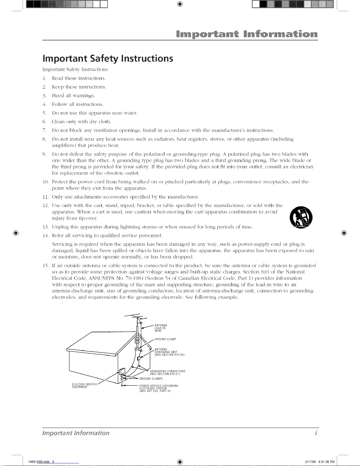
15. If an outside antenna or cane system is connected to tile product, be sure tile antenna or cable system is grounded
so as to provide some protection against voltage surges and built-up static charges. Section 810 of tile National
Electrical Code, ANSIiNFPA No. 70-1984 (Section 54 of Canadian Electrical Code, Part 1) provides information
with respect to proper grounding of the mast and supporting structure, grounding of tile ]eadqn wire to an
antenna-discharge unit, size of grounding conductors, location of antenna</ischarge unit, connection to grounding
electrodes, and requilv,ments for tile grounding electrode. See following example.
@
LEAD IN
WIRE
GROUND CLAMP
ANTENNA
UNIT
(NEC SECTION 810-20)
GROUNDING CONDUCTORS
(NEC SECTION 810-21)
ELECTRIC POWER SERVICE GROUNDING
EQUIPMENT ELECTRODE SYSTEM
(NEC ART 250, PART H)
fmporf_ant fnformaffon
1665105Bindb 3 4_ 2/I7/06 6:31:38PM
Page 4
Important Safety Instructions ....................................... i
Chapter I: Connections and Setup
Things to Consider Before You Connect ..................... 5
Protect Against Power Surges ................................ 5
Protect Devices from Overheating ........................ 5
Position Cables Properly to Avoid Audio
Interference .......................................................... 5
Use Indirect Light .................................................... 5
Check Supplied Parts .............................................. 5
Get the Picture .............................................................. 6
Getting Digital Channels ......................................... 6
Getting Regular (Analog) Channels ...................... 6
Choose Your Connection .............................................. 7
Video (Basic) Connection ....................................... 8
Component Video (Advanced) Connection .......... 8
HDMI/DVI Connection .......................................... 10
VGA Connection ................................................... 12
Plug in the TV .............................................................. 13
Put Batteries in the Remote ....................................... 13
Turn on the TV ............................................................. 13
How to Use the Remote Control to Complete the
Initial Setup ................................................................. 13
Complete the Initial Setup ......................................... 14
Set the Menu Language ....................................... 14
Complete Channel Setup ..................................... 14
What To Expect ........................................................... 15
Watching TV.......................................................... 15
Changing Channels ............................................... 15
Explanation of Jacks (in alphabetical order) ............. 16
Buttons and Other Jacks On Your TV ........................ 17
Front Panel Buttons .............................................. 17
Right Side Input Jacks (when facing back of TV) 17
The Buttons on the Remote Control .......................... 18
Chapter 2: Using the TV's Features
Channel Banner ........................................................... 19
Parental Controls and V-Chip ..................................... 20
How V-Chip Works for USA and Canada ............. 20
Lock/Unlock Parental Controls ............................. 20
US V-Chip TV Ratings ............................................ 21
Blocking Canadian V-Chip Ratings ...................... 22
V-Chip Movie Rating Limit ................................... 23
Block Channels ...................................................... 23
Block Digital Channels .......................................... 23
Front Panel Block .................................................. 23
Lock Time Menu .................................................... 24
Blocking Unrated/Exempt Programs ................... 24
Future Rating Region ........................................... 24
Additional Features .................................................... 24
MultiTask Audio .................................................... 24
Calendar ................................................................ 25
Screen Formats ...................................................... 25
Chapter 3: Using the TV's Menu System
Using the Menu System ............................................. 26
Channel Guide Menu .................................................. 26
Sound Menu ................................................................ 26
Picture Menu ............................................................... 28
Setup Menu ................................................................. 30
Parental Control Menu ............................................... 33
Time Menu ................................................................... 33
Chapter 4: Other Information
Frequently Asked Questions (FAQs) .......................... 34
Troubleshooting .......................................................... 35
Mounting Your TV to the Wall ................................... 38
V-Chip Rating Explanations ........................................ 39
USV-Chip Rating System ...................................... 39
Canadian English V-Chip Rating System .............. 39
Canadian French V-Chip Rating System .............. 40
Autotuning .................................................................. 41
How to Set Up the Autotuning Feature .............. 41
Limited Warranty ........................................................ 42
Care and Cleaning ....................................................... 43
4
1665105Bindb 4 4_ 2/I7/06 6:31:38PM
Page 5
Things to Consider Before You Connect
Protect Against Power Surges
,, Connect all dcvic'es b_'fore you p]ug any of th_'ir pow¢,r cords into th<' wall outk't or pow_,r
strip. NEVER p]ug your TV into an outlet that is control]ed by a wal] switch.
,, Turn <)ftthe T\i and/or device(s) before you connect or disconnect any canes.
,, Make sure all antennas and canes are properly grounded. Re_br to the Important Saf_'ty
Instructions at the beginning of the User's Guide.
Protect Devices from Overheating
', I)on't block ventilation holes on any of the clcvic'cs. Arrange, the dcviccs so that air can
circulate freely.
,, I)on't stack devices.
,, If you place devices in a stand, make sure you allow adequate ventilation.
• If you connect an audio receiver or amplifier, place it on the top shelf so the heate(I air
from it won't flow around other devices.
Position Cables Property to Avoid Audio interference
• Insert each c'ab]c firmly into the designated jack.
,, If you place devices above the T\", route all cables down the side of the back of the T\"
instead of straight down the middle.
• If your antenna uses 300-ohm twin lead canes, do not coil the canes. Also, keep the twin
lead cables away from audio/video cables.
Use indirect Light
Don't p]acc the TV where sun]ight or room lighting wJl] be directed towald the screen. Use so_t
or indirect lighting.
Check Supplied Parts
Check that the following palts were packed witll yore product.
Remote control
Part # R130A1
2 AA batteries Power cord
#'hapter_
Gr(#)bics conl_zin_'d u,ilbin lbis pz/blicalion ar_</'or r(>!)r_>x_nl_zlion on!)<
1665105Bindb 5 4_ 2/I7/06 6:31:39PM
Page 6
ANTENNA/CABLE
ANALOG INPUT
ANTENNA/CABLE
DIGITAL INPUT
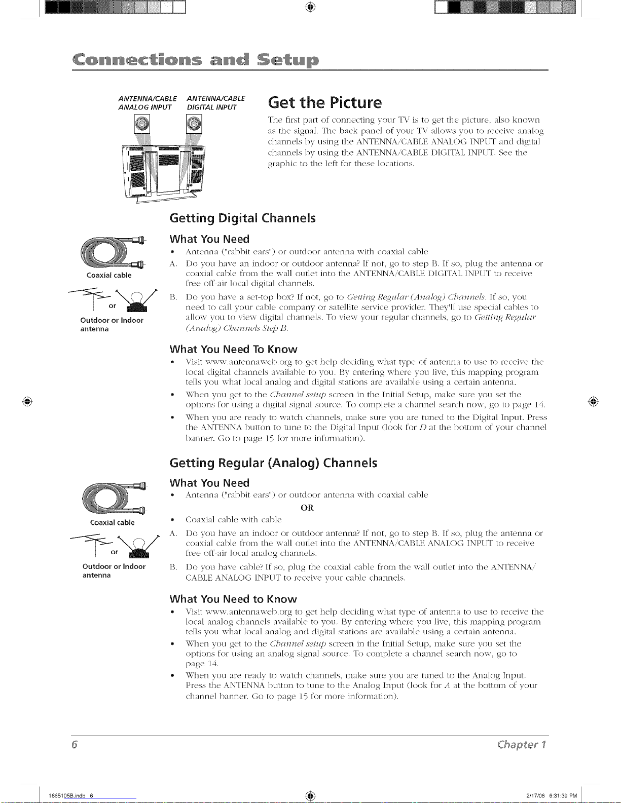
Get the Picture
Tile first p;u-t of connecting your TV is to get the picture, also known
as tile signal. Tile back panel of your T\.' allows you to receive analog
channels by using the ANTENNA,CABLE ANALOG INPUT and digital
channels by using the ANTENNA,(_ABLE I)IGITAL INPUT. See the
graphic to the ]eft for these locations.
Coaxial cable
Outdoor or indoor
antenna
Coaxial cable ®
Outdoor or indoor [3.
antenna
Getting Digital Channels
What You Need
• Antenna ("rabbit cm_s'') or outdoor antenna with coaxb] cable
A. I)o you have an indoor or outdoor antenna? If not, go to step B. If so, plug tile antenna or
coaxial came _iom the wall outlet into the ANTENNA/CABLE {)IGITALINPITT to receive
fis,e oft_air local digital channels.
B. I)o you have a set-top box? If not, go to G'#ttin2 R<_Uar (Anal(4_) CT_a_?t?els.If so, you
need to call your came company or satellite service provider. They'll use special cables to
allow you to view digital channels. To view your regular channels, go to (,:(,t/in2 R<g_Uar
(AJlal(4_) CT?aJnml.s"_STg])1_.
What You Need To Know
- Visit \v\v\v.antcnna\vcb.org to get help dccicling what type of antenna to use to rcc'(qvc the
local digital channels available to you. By entering where you live, this nmpping progran_
tells you what local anaklg and digital stations are available using a certain antenna.
• When you get to tile CT?anJwl.s(>/z@screen in tile Initial Setup, make sure you set tile
options for using a digital signal source. To complete a channel search now, go to {)age 14.
• When you arc ready to watch channels, make sure you alt, tuned to tile Digital Input. Press
the ANTENNA button to tune to the Digital Input (look for/) at rile botton_ of your channel
banner. Go to page 15 for more infornmtion).
Getting Regular (Analog) Channels
What You
® Antenna
Need
("rabbit em's") or outdoor antenna with c'oaxia] c'ab]c
OR
Coaxial cable with cable
I)o you have an indoor or outdoor antenna? If not, go to step P;. If so, plug tile antenna or
coaxial came from tile wall outlet into the ANTENNAiCAI$LE ANALOG INPI TTto receive
free off-air local analog channels.
I)o you have cable? If so, plug tile coaxial cable from tile wall outlet into rile ANTENNA/
CAI$LEANALOG INPI TTto receive your came channels.
What You Need to Know
• Visit \v\v\v.ant(,nna\v(q).org to g(,t help deciding what type of antenna to c]s(' to r(,c'(,ivc the
local analog channels available to you. P;y entering where you live, this mapping progran_
tells you what klcal anaklg and digital stations are available using a certain antenna.
• When you get to tile CT?a,nwl.s_>tz@screen in the Initial Setup, make sure you set tile
options for using an analog signal source. To coral)]ere a channel search now, go to
[)age 14.
- When you are ready to watch channels, make sure you are tuned to the Anak)g Input.
Press the ANTENNA button to tune to the Anak)g Input (k)ok for A at the botton_ of your
channel banner. Go to [)age 15 for more infornmtion).
ChaSetl
1665105Bindb 6 4_ 2117106 6:31:39PM
Page 7
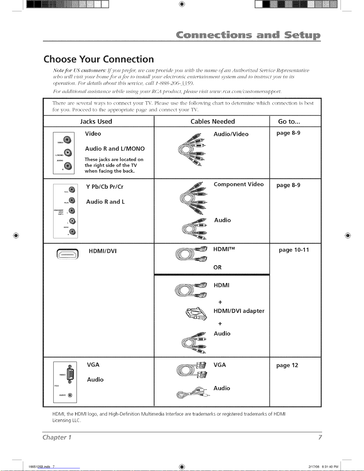
Choose Your Connection
Note for {L_"customenq: Ijvo_ p_'e/_< u e ca_z p_'oz'icle yoz_ u i/b /be name cJcln A z_/borized &'mice Represen/clH_'e
zl bo l_ ill z,#i/ yozlr bomej'o_" a /'_>e/o install )'oz/_" eldc/ronic eJT/e_'lainmen/ ._Fs/en_ and/o ins/?7/c/ yoz_ in ils
c,pe_'a/ion. I:o_" ch>/ails aboz_/ /Dis .s_lT'icd, call /-,S%%'-20d-.-_.7 59.
Fo_" additional assistance zl bil_" z_sin_ yoz/_" RCA p_'odzm/, please z,isit zl zuzl ._'ca.com/k;z_s/on_e_'sztppo_<
There are severn] ways to connect your T\,'. Please use the following chart to determine which connection is best
for you. Proceed to the appropriate [)age and connect your TV.
Go to...
page 8-9
vloEo_
L/_ONO0
_U_IO
o@
L@
AUDIO
Jacks Used
Video
Audio R and L/MONO
These jacks are located on
the right side of the TV
when facing the back.
Y Pb/Cb Pr/Cr
Audio R and L
HDMI/DVl
VGA
Audio
Cables Needed
Audio/Video
Component Video
Audio
HDMI T_
OR
HDMI
+
HDMIIDVI adapter
+
Audio
VGA
_>, Audio
page 8-9
page 10-11
page 12
HDMI, the HDMI logo, and High-Definition Multimedia Interface are trademarks or registered trademarks of HDMI
Licensing LLC.
C'hapeerl
7
1665105Bindb 7 4_ 2/I7/06 6:31:40PM
Page 8
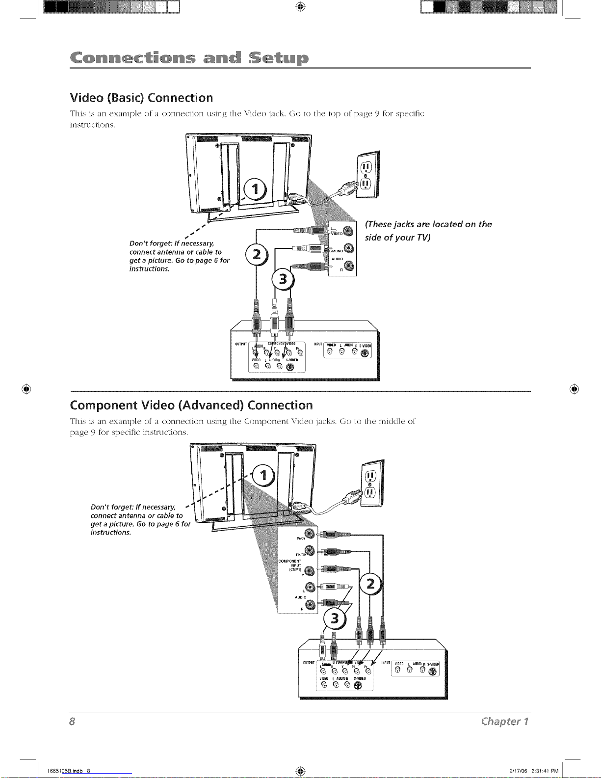
Video (Basic) Connection
This is an cxamp]e of a connecthm using the \,,'idco jack. Go to the top of page 9 fol specific
in str u ction s.
S
4*
S
Don't forget: ff necessary,
connect antenna or cable to
get a picture. Go to page 6 for
instructions.
(These jacks are located on the
side of your TV)
Component Video (Advanced) Connection
This is an example of a connection using the Component Video jacks. Go to the middle of
page 9 for specific instructions.
Don't forget: If necessary,
connect antenna or cable to
get a picture. Go to page 6 for
instructions.
<hapterI
1665105Bindb 8 4_ 2/I7/06 6:31:41 PM
Page 9
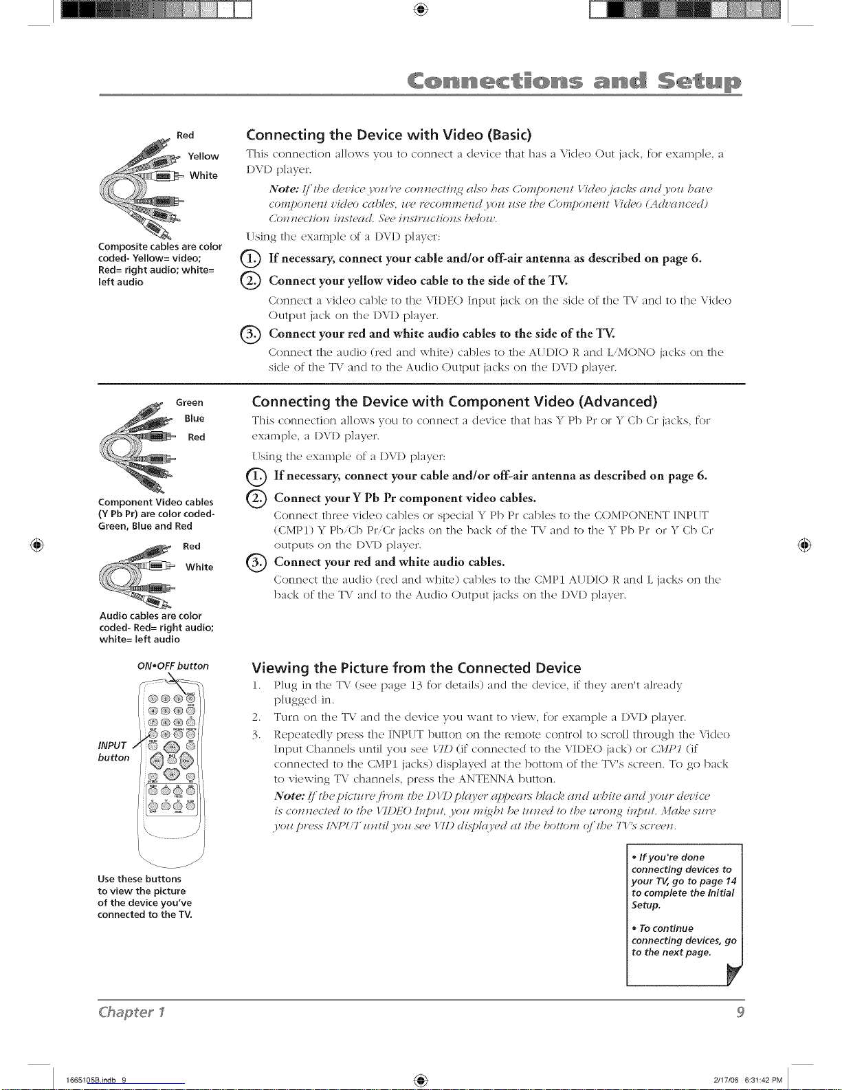
Red
Yellow
White
Composite cables are color
coded- Yellow= video;
Red= right audio; white=
left audio
Connecting the Device with Video (Basic)
This connection a]Jows you to connect a device that has a Video (:)Litjack, for exampJe a
DVI) player.
Note: (i lhm d_?vicmj,ozz _"mconnmclhz 2 (_/so ht_s O)rHponmnl 17dmo jg_cks and.Fozz hnz,m
COI'I/[;OII_?Ill z,idmo cah/e.< _ze r(?col'nn/_?l/(l j<)I/ zls_?I/?_?Cnl'npOll_izl 17d(?o (Advaucmd)
(]O]I]_CCIIOH IIZNI_?(I(!. ,_'(?(? [IZS/EILCIIOllS I)C/O_I'.
Using the cxaml)]e of a D\l) l)]ayer:
Q If necessary, connect your antenna as on page
cable and/or off-air described 6.
Q Connect video cable the side of the TV.
yellow
your
to
Conn(wt a xideo cab](, to th(, VIDEO Input jack on the skle of the TV and to the Vkleo
Output jack on the I)VD p]ayer.
Q Connect red and white audio cables to the side of the TV.
your
Conncct tfx(, audio (led and white) cables to the AUDIO 1,' and L,M()N() jacks on the
si(le of the T\ and to the Au(lio Output jacks on the I)VD p]ayer.
Green
Blue
Red
Component Video cables
(Y Pb Pr) are color coded-
Green, Blue and Red
Red
White
Audio cables are color
coded- Red= right audio;
white= left audio
Connecting the Device with Component Video (Advanced)
This connection allows vou to connect a device that ha, _* Pb Pr or _* Cb CI jacks, re1
cxan_p]e, a I)\"1) p]aycl.
(Tsing file exmnp]e of a DVI) player:
Q If connect cable rand/or off-air antenna as described on 6.
necessary, your
page
Q Connect Y Pb Pr video cables.
your component
Conncc't t]lrcc xideo c'ab]cs ol spcc'ia] Y Pb P_ c'ab]es to the COMPONENT INP_ TT
(CMPI) Y Pb,Cb Pl"'Cr jacks on the back of file TV and to file Y Pb 1)1"or Y Cb Cr
OLItDLItSon the {)\l) ]_)]ay(n'.
Q Connect red and white audio cables.
your
Connect the audio (Ted and whir(,) cables to the CMPI AUDIO R and L jacks on the
back of file TV an(I to file ALl(lie (1)tltput jacks on the I)VI) p]ayel.
ON*OFF button
I
\.
Usethese buttons
to view the pkture
of the device you've
connected to the TV.
Viewing the Picture from the Connected Device
1. P]ug in the TV (scc page 13 for (Ictails) and the (kwic'c, if they m'cn't a]rcacly
plugged in.
2. Turn on the T\; and the device you want to view, for exmnp]e a I)VI) player.
3. Repeated]y press the INPUT button on the remote control to scroll through the Video
Input Channels until you see /TD (if connected to the VII)EO jack) or C.1IP1 (if
connected to the CMPI jacks) (lisp]ayed at the bottom of the TV's screen. To go back
to viewing T\; channels, press the ANTENNA button.
Note: I/I/?epictz_r<fi'om t/?e DI T) plco,er (q)!)('<l_>blclck and z_hite and yoz_r clcz'ice
is conn(,c/ed lo t/_e 17I)EO hzpHt .Vozl n!{ght/)e tzzn('d to the z_ro_z2 inpzzt. .lhzke szz*'(,
3,o17pr(>.<s"L\7"UT z_tztil.I,oz_.<,(,e/71.)ULSt)I<o'(>Uat the botlom (?/'the T1".<,"so'¢(,*z.
• Ifyou're done
connecting devices to
your TV, go to page 14
to complete the Initial
Setup.
• 7"0 continue
connecting devices, go
to the next page.
C'haSer
1665105Bindb 9 4_ 2117106 6:31:42PM
Page 10
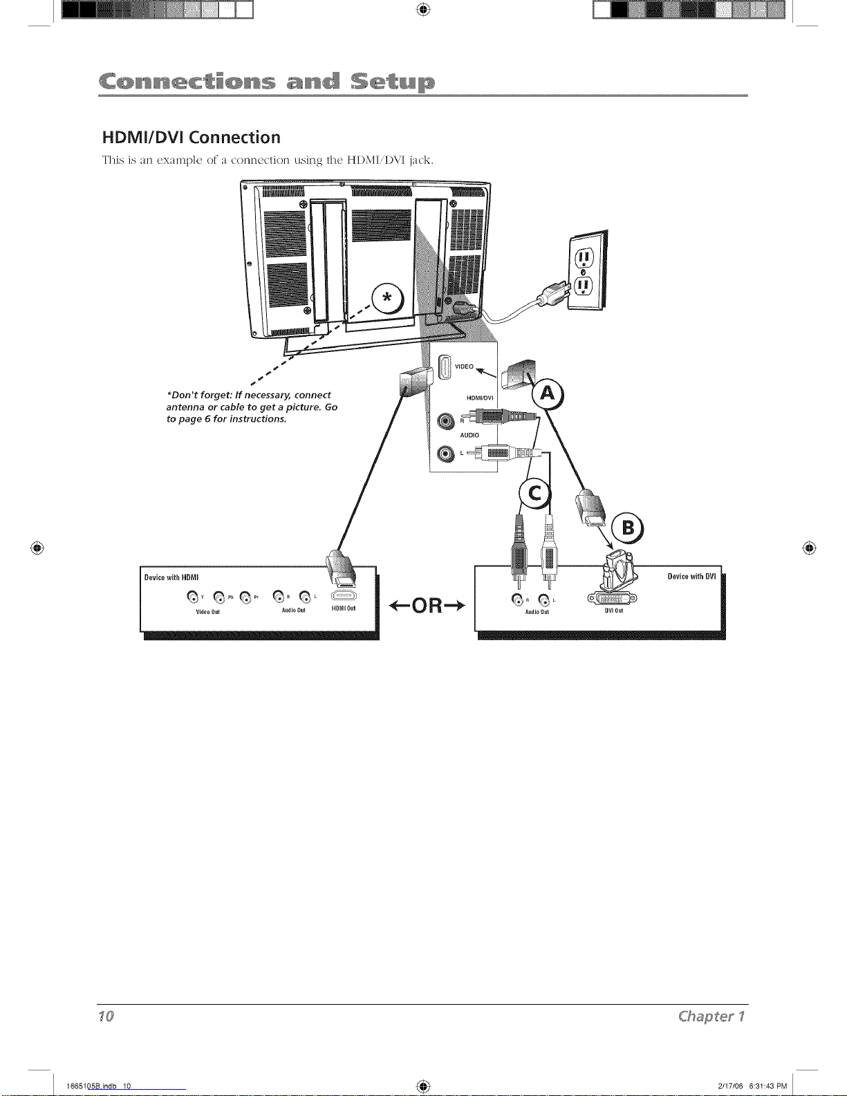
HDMI/DVI Connection
This Js nn exmnl)]e or _ cormccfion using tile HDMI,I)\,'I j_(k.
i
*Don't forget: If necessary, connect
antenna or cable to get a picture. Go
to page 6 for instructions.
HDMI/OVI
@
AUDIO
@
DevicewithHDMI
Video Out Audio Out HD_II Out
DevicewithDVm
Audio Dut [JVIOut
<hapterI
1665105Bindb 10 4_ 2/I7/06 6:31:43PM
Page 11
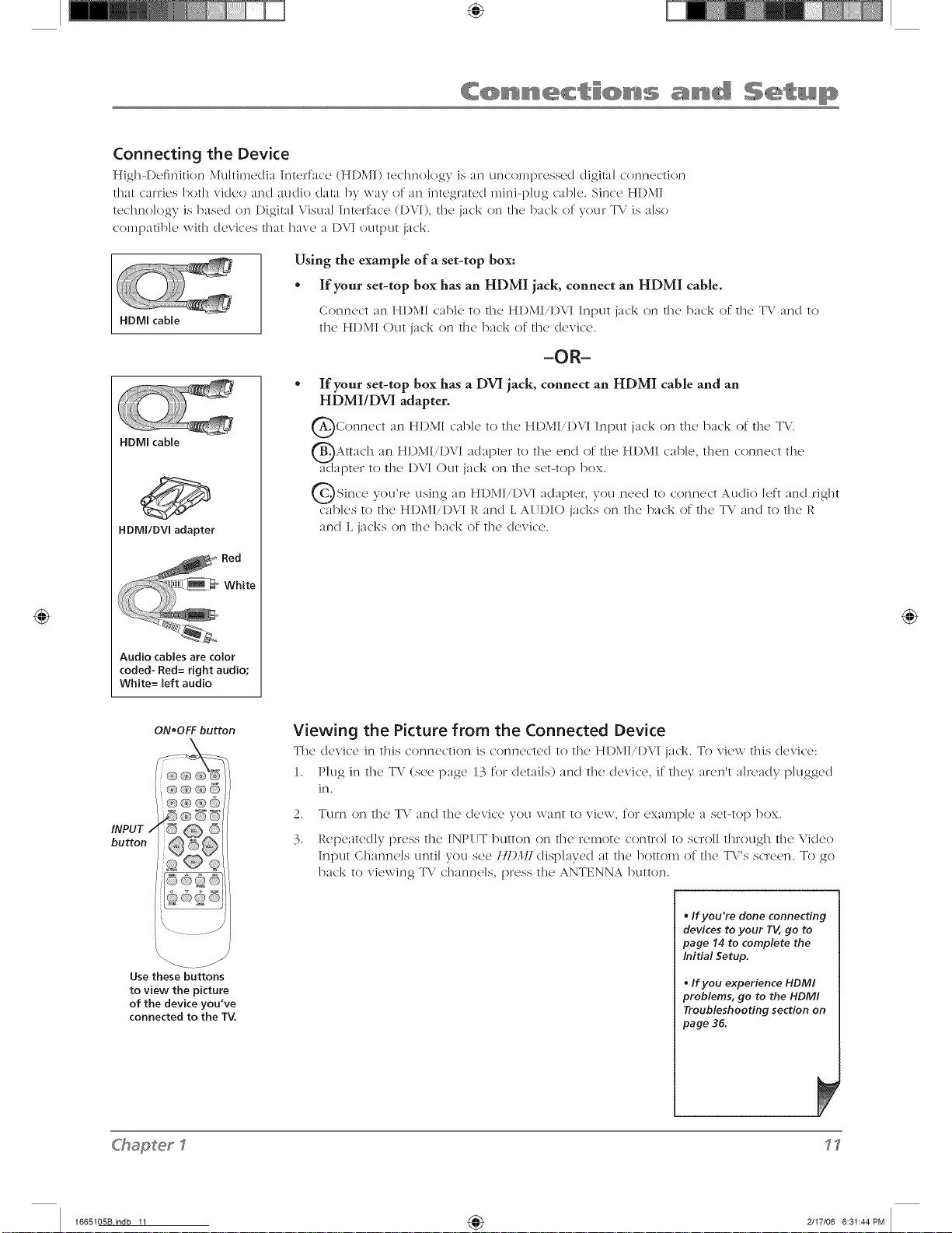
Connecting the Device
Hig]l-D('finition Multimedia Inmrfa(x' (HDMI) tcclm(Jogy is an un('omprcsscd digim] connc'ction
tllat canJes/)ot]l video and audio dam by way of an integrated mini-p]ug cab]e. Since HDMI
techno]ogy is based on Digital Visual Interface (1)VI), die jack on die back of your T\' is also
c()lnpatib]e with devices that have a 1)VI output jack.
HDMI cable
HDMI cable
Audio cables are color
coded- Red= right audio;
White= left audio
Using the example of a set-top box:
* If your set-top box has an HDMI jack, connect an HDMI cable.
Conn(wt an HDMI cab](' to th(' HI)MIiD\"I Input jack on the back of the TV and to
the HI)MI Out jack on the back of the device.
-OR-
If your set-top box has a DVI jack, connect an HDMI cable and an
HDMI/DVI adapter.
QConnect an HI)\,II cab]e to the HI)MI,I)VI jack on the back of the TV.
Input
QAttach an HI)MI,DVI adapter to the end of the HI)MI cable, then connect the
adapter to the I)VI <)ut jack on the set-top box.
Q Since you're using an HDMI,DVI adapter, you need to connect and right
d_ [a([J() ]eft
cables to the HDMIiDVI R and L AUDIO jacks on the back of the TV and to the R
and L jacks on the back of the device.
ON,OFF button
Viewing the Picture from the Connected Device
The dcvic'e in this connection is connectc<l to the HI)MI,I)VI jack. To view this device:
1. P]ug in the TV (see page 13 for details) and the (levite, if they a_en't already p]ugged
in.
2.
3.
TLIFr] or] t]l<} W\ ar](] tile! (I<!'\Jc<! VO/I \va13t to V1Q\v, fo]" cxalnp]c a S<!t-[o[3 ])ox.
Repeatedly press the INPIJT button on the re,note control to scroll through the Video
Input Channels until you see /ll) l_l displayed at the botto,n of the TX's screen. To go
back to viewing TV channe]s, press the ANTENNA button.
\
Usethese buttons
to view the picture
of the device you've
connected to the TV,
ChaSerl
,, If you're done connecting
devices to your TV, go to
page 14 to complete the
Initial Setup.
, If you experience HDMI
problems, go to the HDMI
Troubleshooting section on
page 36.
1665105Bindb 11 4_ 2/I7/06 6:31:44PM
Page 12

VGA Connection
This is an example (2 a connection using the \GA jacks.
S
s
S
s
S
S
Don't forget: If necessary,
connect antenna or cable to
get a picture. Go to page 6 for
instructions.
Connecting the Device
This connection al]o\\-s you to connect to a persona] compute;.
1. If necessary, connect your cable and/or off-alr antenna as described on page 6.
2. Connect your monitor cable.
Connect on(' end of a 15-pin monitor cab](, to the VGA VII)EO jack on the TV and the
other end to the PC's video outpt]t jack. Note, if your PC's video output isn't 15-pin, you'll
need an adapter that can connect to a 15-pin monitor cane.
3. Connect your audio cable.
Connect a 3.5 mm stereo mini pin cable (sometimes rcfcl'r(</to as 1'8" st('*'('() mini pin) to
the VGA AUDIO jack on the back of the TV and the other end to the Au(IJo Output jack on
the PC.
Notes: 7be m(Iximzow panel r(<solz#/k)_z is 1.360 x 76,_'. 1_(,szo'(, to set.yozo" P(; to the
cotv'(,(:t tllonitor OZlI[)_I/ selting_
7P(, .lhdtiTbsk A z_dio >_jiutzo¥" (dlo.'syoz_ to ll.st(,n to tb(, sozo_d ii'om tile TV while the P(;
is coJmect(,d. (;o to p((_(, 24for more iJff'orm(ltioJl.
Viewing the PC
1. P]ug in the TV (see page 13 for details) and the PC, if they aren't a]ready p]ugge(I in.
2. Turn on the WVand the PC.
3. P;ess the INPUT button on the remote cont;o] to sc;o]] th;ough the Video Input Channels
until you see l'(L4 disp]ayed at the bottom of the T\'s sc;een. To go back to viewing T\"
c]mnne]s, press the ANTENNA button.
<hapterI
1665105Bindb 12 4_ 2/I7/06 6:31:45PM
Page 13

Plug in the TV
Plug the end of the power corcl kite the back of @c T\.. Plug t]l_' ethel end into a grounclccl
wall outlet. Insert the plug completely into the outlet. I)o not plug into an outlet controlled by
a light switch.
Put Batteries in the Remote
• Rcmow, the bam'ry c'ompm'tmcnt c'ovcr from the back of the remote by pushing the mb
and lifting off the cover.
• Insert two fresh batteries. Make sure the polarities (+ and -) are aligned correctly.
- Replace the cover.
Turn on the TV
Ttlrn on yotlr TV by plessing the Power button on the front of the TV ol ON-OFF on the
remote control.
button
How to Use the Remote Control to
Complete the initial Setup
The technical term is "Navigation" - how you move through the on=
scr(x'n IllL!nus. The t]]('orv is th(' s_/in(2 t]]rO/lgho/lt t]](2 inen/l scr(,L!ns:
hig]?light yore choice and select it.
To highlight a men u item, press the arrow buttons on the remote to
highlight one of the items listed on the screen. Use the up or (Iown
arrow button to move up or down. Use the right or left arrow button
to view other selections for a menu choice or to display a sul>memk
More than one selection (lisplays, for example, O_z...; a menu choice
with a sub-menu displays dots (...).
Note: II{@l{@t_,d me(ms that tb¢ met_z¢ itr,,_zstands- oztt./)'o_
ot/?er menzz ite*_zson the/ixt ((]/)/)U(I?N (/(lr/au?; br{gbter, era
d(/[l'_>zw¢ltcolo*9.
rip
Toaccessthesetupmenusmanually,pressMENUand
chooseSetup.
C'haSet_
1665105Bindb 13 4_ 2117106 6:31:45PM
Page 14
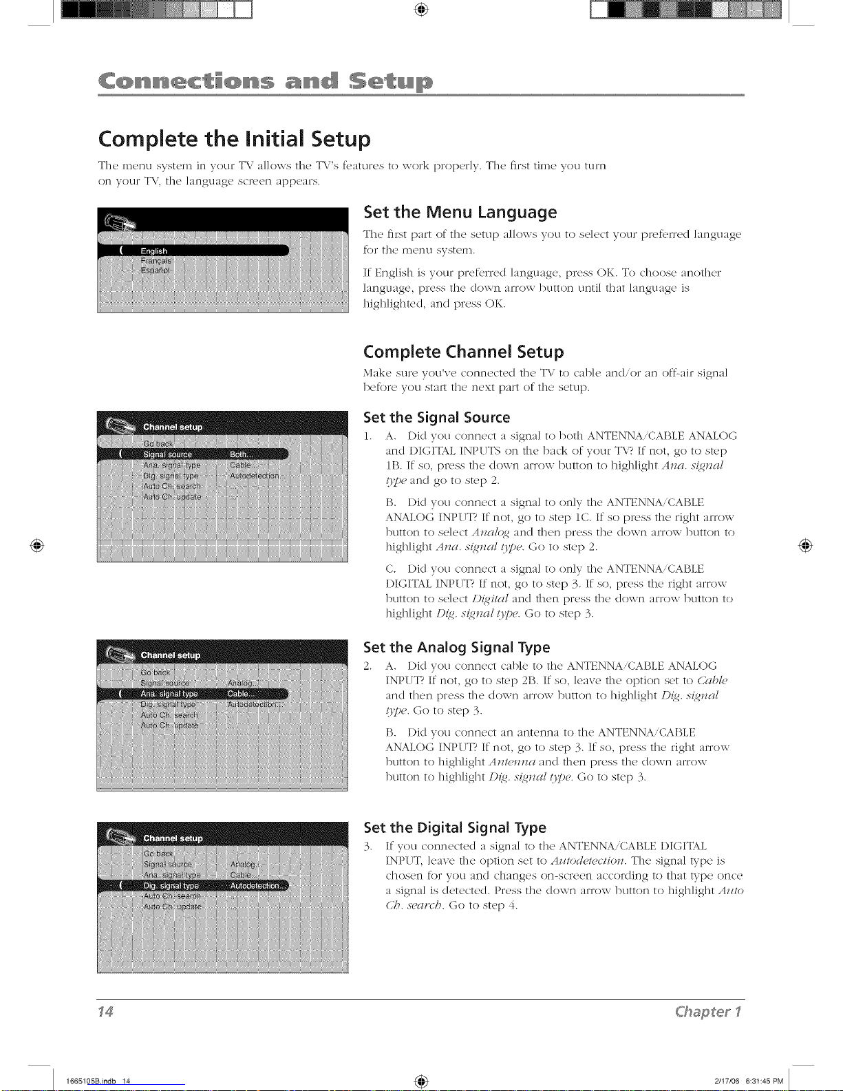
Complete the initial Setup
The menu system in vour TV allows the TV's features to work properly. The first time you turn
on your TV the language screen appears.
Set the Menu Language
The first part of the setup :dk)\vs you to so]cot your pn, tbrrcd language
for the menu system.
If Eng]ish is your preferred ]anguage, press OK. To choose another
language, press the down arrow button until that language is
highlighted, and press OK.
Complete Channel Setup
Make sure you've conncctcd the T\; to cable and/or :m otL:_ir signal
before you star* the next part of tile setup.
Set the Signal Source
1. A. l)id vou connect a signal to both ANTENNA/CABLE ANALOG
and DIGITAL INPUTS on the back of your TV? If not, go to step
lB. If so, press the down arrow button to highlight At_a. s{_t_al
O7,,eand go to step 2.
B. Did you connect a signal to only the ANTENNA/CABLE
ANALOG INPUT? If not, go to step 1C. If so press the right arrow
button to se]ect At_alqg and then press tile down arrow button to
highlight AJza. s{gnal 13pe. (3o to step 2.
C. Did you connect a signal to only the ANTENNA/CABLE
I)IGITAL INPUT? If not, go to step 3. If so, press the right arrow
button to select D{gital and then press the down arrow button to
highlight/){g, s{g_zal O7,,e.Go to step 3.
Set the Analog Signal Type
2. A. Did you connect cable to the ANTENNA/CAI_LE ANALOG
INPUT? If not, go to step 2B. If so, leave the option set to C?fbk,
and then press tile (Iown arrow button to highlight 1){_. s_nal
tty)e. Go to step 3.
B. Did you connect an antenna to the ANTENNA/CABLE
ANALOG INPUT? If not, go to step 3. If so, press the right arrow
button to high]ight Antenna and then press tile down arrow
button to highlight [){g. s{gnal Ope. Go to step 3.
Set the Digital Signal Type
3. If you connected a signal to the ANTENNA/CABLE I)IGITAL
INPUT, leave tile option set to Azztod_'te(tion. The signal type is
chosen for you and changes on-screen according to that type once
a signal is detected. Press the (Iown am)w button to high]ight Az_to
U?. sg,gltVh.Go to step 4.
f4
<hapterf
1665105Bindb 14 4_ 2/I7/06 6:31:45PM
Page 15

if you connected cables to the ANALOG
and DiGiTAL iNPUTS, the TV runs 2 separate
channel searches,
Look for the A at the bottom of the screen to
make sure you're on the Analog input.
Look for the D at the bottom of the screen to
make sure you're on the Digital input,
Complete the Channel Search
4. Ew'n though the initial channel search can take sew'ra] minutes,
you must complete it in order for your T\..'to display channels and
programming. Press OK to begin the dmnne] search. The menu
shows the T\.' is running a channel search. When it's complete, the
C/>at_t_elsetup men u remains on-screen. To exit tile men u system,
press CLEAR.
Some dmnnels might have been found during tile channel search
that are unavailable to view and you might want to get rid of these
so they don't appear as you d-range channels. To do this press OK
(the Li:,t and LabeLs menu appears). Note that removing channels
fiom w)ur channel list may be time consuming, so w)u might want
to c/o it later. Go to page 30 for details on editing your
channel list.
What To Expect
Watching TV
', Remember: If"you have an analog signal connected to vour
ANTENNA/CABLE ANALOG INPUT, then look for an A at the
bottom of tile screen to make sure you're tuned to tile Analog
input. Press the ANTENNA button if the A isn't appearing.
Analog video is sent in a 4/3 format, whirl] vour T\"displays these
channels in a 16/9 format. Press tile ZOOM+i- button to view the
different formats avai]ab]e. Go to page 25 for more explanation of
screen Jorn]ats.
Remember: If you have a digital signal connected to your
ANTENNA/CABLE DIGITAL INPUT, then look for a D at the
bottom of tile screen to make sure you're tuned to the Digital
input. Press tile ANTENNA button if the /) isn't appearing.
Most digital video is sent in a 16/9 format whidl does fill w)ur
screen, but sometimes is sent in 4/3 which does not fill your
screen. It depends on how the station or source device is
formatting the video. If there are bars on-screen, press the
ZOOM+/- button to try a different format that may eliminate
the bars. Go to page 25 for more explanation of screen formats.
Changing Channels
- Digital channels can haw' both primary channels (like the an:Jog
channel number) and sub-channels. First tune to tile Digital Input
bv pressing the ANTENNA button and look for a D at the bottom
of tile screen. To tune to a digital channel with a sub-channel,
enter the primary dmnne] number, then press the right arrow
button. Enter tile sub-channel number and press OK.
I)epending upon tile type of signals you have connected to your
HDT\', you might notice that the channels change slower than
you're used to. This is perfectly normal. Digital cable channels
sometimes take longer to tune.
C'haSerl
1665105Bindb 15 4_ 2/I7/06 6:31:46PM
Page 16

Explanation of Jacks (in alphabetical order)
This section describes tile, jacks on tile, back panel of your TV. There m'e several ways to
connect devices.
ANTENNA!CABLE ANALOG INPUT Lets you connect a coaxial cable to receive tile signal
from the antenna, cable, or cable box.
ANTENNA!CABLE DIGITAL INPUT Lets you connect a coaxial cable to receive tile signal
from the antenna, digital cable, or digital cable box.
COMPONENT INPUTS Lets you connect a device that has component vkleo jacks, such as a
I)VI) player.
• CMP1 YPb/Cb Pr/Cr (Component Video) Provides optilnum picture quality because the
video is separated into three signals. Use three video-grade or component video cables for
the connection. When using CMPI Y Pb.Cb PriCr, make sure you connect left and right
audio cables to the CMPI L and R AITI)IO jacks.
• CMP1 LAUDIO Provides left audio connection when using the CMPI video inputs. The let}
audio connector is usually white.
• CMP1 RAUDIO Provides right audio connection when using the CMP1 video inputs. The
right audio connector is usually red.
• CMP2 YPb/Cb Pr/Cr (Component Video) Same as described for CMPI Y Pb/Cb PNCr and
CMPI Audio above. Make sure you connect the let} and right audio cables to the CMP2 L
and R AITI)IO jacks.
Lets you connect a device, such as a digital cable box, with an HI)MI or aHDMI/DVI Input
DVI output.
HDMI/DVI INPUT (High-Definition Multimedia Interface/Digital Visual
Interface) Provides an uncompressed digital connection that carries both video and
audio data by way of an integrated mini-plug cable. Since HI)MI technology is based on
Digital Visual Interfuce (I)VI), the jack on the back of your TV is also compatible with 1)VI
devices.
* L AUDIO (used for DVI only) Provides left audio connection when using the I)VI jack.
The let} audio connector is usually white.
- RAUDIO (used for DVI only) Provides right audio connection when using the I)VI jack.
The right audio connector is usually red.
Note: l¢umember to connect the Iql'land r{_bt azidio eablus b_,eazi.su/b_, DU cablu ea*vw,s
o_dy tbe picm,v s_g_lal. Jlot the soz_ud.
MONITOR OUT Connect a VCR or DVD-recorder to record digital and analog programs fro,n
the Digital or Analog Input (excluding copy-protected progralns and component video formats)
while the TV is turned on. You must leave the T\,' on the same channel you are recording.
AUDIO Use the Audio Out jacks when using the MONITOR OIJTPIJT Video jack or use these
jacks by themselves to connect an audio receiver to the T\..' for enhanced sound quality. If you
use these jacks to receive your sound, you don't need to connect the speakers supplied with
the T\.'. Make sure you set the Audio output correctly in the Adz'armed N(,//it?2s Abznzd menu.
Go to [)age 28 for more information.
- L (Audio) Provides left audio connection. The left audio connector is usually white.
• R (Audio) Provides right audio connection. The right audio connector is usually red.
<hapter
1665105Bindb 16 4_ 2/I7/06 6:31:46PM
Page 17

VGA Connect yotlr comptlter , or ot]ler device wit]] a \GA output, to this jack using a 15 pin
I)-sub cable.
VGA AUDIO (Stereo mini jack) I%c to obtain sound when a PC is connected to the VGA jack.
ITS(' a ._. IIM]] 3t(21"(2o II]JnJ Dill. ('aJ)](2 (sollletilllcs l'(2f(21"r(,(] 1o as 1 (_" sto](2o I]]Jni pin) to ('onnLtc[ a
PC to your TV. Go to page 12 for more information.
Buttons and Other Jacks On Your TV
Front Panel Buttons
It you cannot locate your remote you can use the front panel buttons of your T\" to operate
many of the TV's features.
MENU Brings up the TV Main menu.
VOL > Increases the vok_me. In the T\/n_enu system, acts like tile right arrow button on the
remote control and adjusts menu controls.
VOL < Decreases the vo]u,ne. In the T\.' menu system, acts like tile ]eft arrow button on tile
remote control and adjusts menu controls.
CH ^ Scans up through the channel list. In the T\.' menu system, acts like tile tip arrow button
on tile remote control and adjusts menu controls.
CH v Scans down through the channel list. In the T\; menu system, acts like the down arrow
button on tile remote control and adjusts menu controls.
POWER Turns the TV on and off.
Right Side Input Jacks (when facing back of TV)
L/MONO and R AUDIO Itccciw's audio ti'o*n anofl-tcr d<'vic<' such as a c_incor<h.T, video galn<'
console, VCR, or I)Vl) [)layer. Use when connecting to tile VII)EO or S-VII)EO Input.
VIDEO Input Receives video tio,n another device such as a camcorder, video game console,
VCR, or DVD player. To access a device connected to the VI1)EO jacks press tile INPUT button
on your remote until /7I) appears at tile bottom of tile screen.
S-VIDEO Input Allows you to connect an S-Video cable from another device. Make sure
you also connect audio cables from the device to the TV. To access a device connected to the
VIDEO jacks press tile INPUT button on your remote until $/71) appears at tile bottom of tile
screen.
(Headphones) Allows you to connect headphones to listen to the sound con_ing froJn the
T\.. To adjust vo]un_e contlo] of the ]lea(Ip]lones go to t l_ Hdadp/?o_, 5CIIiH_5" option Jn t]lC
,%'Olllld ]]l(2n tl.
#'haSer
_7
1665105Bindb 17 4_ 2/I7/06 6:31:47PM
Page 18

Remote control part number
R130A1
Note: I/]_,ozz tu'_'d to mid(iF:(" yoz_r
z'(,mot(', c(1111-800<_)_8-()3 7EL A
shippin(_Find h(nzd/in(<ii'(,, (nEd t/?("
(lppropri(m, x(t/_,.st(t.:v,z_ill DE,ch(l<_ed
z/pon oi%l_'riJ<_.I I(me )/ozzr l Ts(t.
M(/._t(,rd,?w(l. or Di._coz,(,r (,7lt¥t r_'(/d.y.
The Buttons on the Remote Control
Arrows 17sod to highlight (lif[crent items in the T\" menu and to adjust
the menu controls.
(0-9) Number Buttons Enter channel numbers and time settings directly
through the remote control.
To enter a one-digit analog channel, enter a zero first. To enter a two-
digit channel, press the two digits. To enter a three-digit channel press
and hold the "1" button until "1" and two dashes (--) appear, then add
the second two digits. Example: to tune to channel 123, press and hokl
1 until "1- -" appears, release the 1 button and then press 2 and 3.
To enter a digital channel with a sub-channel, enter the main channel,
then press the fight arrow to enter the sub-channel and press OK.
ANTENNA Switches between Anak)g and Digital input channel. When
tuned to an input, press to go back to the most recently used tuner
(Antenna or Digital input).
CC For the Analog input, displays the CF;.s-(,t/#<_and Anal(),_ CU hP(';
for the Digital input, (lisp]ays the CF.'.sY>t/it?<_,[){_it(ll CF.'{Tpe, and D{_ital
C(;pr_,.s-et.
CH + or CH - Scan up or down through the current channel list. Press
once to change the channel up or down; press and hold to continue
dmnging channels.
CLEAR Removes any menu or display £iom the screen and returns
you to normal viewing.
FAV (Favorite) Press to browse the channels set in your ]:(lz,orite List.
Go to page 31 for more information.
FREEZE '_\,llile watching T_, freezes the picture. Press OK again to
unfreeze.
GO BACK Returns you to the previous channel
INFO Brings up the channel banner; press again to dear the screen.
INPUT Accesses the available video input channels (/7D. 817I).
(/.llP/. cr.1]/)2. /'(iA, and HI).IH). Press the CH+ or CH- or ANTENNA
button to resu,ne TV viewing.
MENU Displays the menu system. If in a sub-menu, takes you back
to the previous menu.
MUTE Re(luces the TV's volume to its n_inin_um level Press again to
restore the vo]unle.
OK When in the menu system, displays sub-menus.
ON.OFF Turns the TV on and off.
PRESETS For the Analog input, displays Pic/zz*> and ,S'ozzndpn(,.set
option. For the Digital input, displays Pictzzzw and Noz¢_zdpt'(,.se/;and
[){_. U'I.Azid. Lan_. and C71+/(31- bzdtous.
SKIP Press oncE' beforE' d-ranging chann(,ls and thE,TV \\-ill wait 30
seconds before returning you to the original channel. Press repeatedly
to ad(I more time. Press CLEAR to cancel SKIP.
SLEEP Sets the T\.' to turn off. Each time you press the right arrow
button the clock adds 5 minutes (up to 240 minutes).
SOUND For the Analog input, displays the 7hue cont,>l menu. For
the Digital input, displays Pi(tzzr(, and ,5'ozl_zdpt'(,.sY,t;and [)_. C_1.Az_d.
Lang. and C71÷/(3/- bzlttons. In VGA mode, switches to the T\."s au(lio.
VOL-orVOL + Decreases or increases the TX."svolume.
ZOOM - or ZOOM + Press left or right to change the size of the
picture on-screen.
<hapter?
1665105Bindb 18 _ 2/I7/06 6:31:47PM
Page 19

Channel Banner
There are sex'era] indicators that might appear when you press the INFO button on the re111otc.
This display is called the Channel Banner. The following list describes the items on the Channel
Banner screen (left to right and top to bottom).
Analog Channel Banner
SAP
cc
Commercial skip 0.'30
Stereo
_ur 09/29/05
A lO CBS (analog)
D 10-1 CBS (digital)
4/3 or 16/9format
Zzz 00:25
06:05pro
Digital Channel Banner
The current channel is broadcasting SAP (Second Audio Program)
1;] forln}/t] oy],
Close(I Captioning is available on the current channel.
Shows the time remaining on the commercial ski[) (SKIP) timer.
Sl(,r¢o appears when tile current channel is broadcasting in stere<).
Mono appears when tile current channel is broadcasting in mono.
Current date.
The A means it's an analog channel. The channel and program
you're currently viewing are displayed.
The D means it's a digital channel. The channel, sub-channel (if
availab]e), and program you're currently viewing aredisp]ayed.
Curlx.)y]t SCl'Lk'll fornlat. If 1]112r12 }/r(2 13]}lcIK bars oyl-screeyl you Inight
be able to get rid of thclll 13}7 pressing the ZOOM buttons on the
rclllote. Go to page 25 for IDore JIlforlllatioI1 oil Scl'e(2D forlD_Ks.
Current time left on sleep timer, if the sleep timer is set.
Current time.
ChaRter2
Grglphh;s (;olll(Hized milhill lhLspzlbli(;(_lioll (_l'<ior r_,pn,selll(_lion olz{),.
1665105Bindb 19 4_ 2117106 6:31:47PM
Page 20

Parental Controls and V-Chip
The' choice's in the' {A'/'-(.77ip and (kmridgt 1"-(_7?ipm_'nus involve softwm'e inside your T\"
(retbrred to as V-Chip) which allows you to block T\/ programs and movies. T\/ programs can
be blocked by age-based ratings, such as T\.'-MA, which is explained on [)age 21. If available,
TV programs can also be blocked by content, such as adult language (L). This is explained on
[)age 22. Movies can only be b]ocke(I by age-based ratings. This is explained on [)age 23.
Once you block programs, you can unblock programs by entering a password.
By default, the software inside your TV is turned off or unIocke(I. For instructions to lock
V-Chip, see below.
Note: P(lrunl_l/ con/ _o/s_lHnqs elru no/ell,eli/elb/_</'or [H) III or (iMP1 or 2 in!2llLv.
How V-Chip Works for USA and Canada
V-Chip reads the' program's agc'-bas_'drating (T\"-MA, T\"-I< _'tc.) mid cont_'nt thcm('s
[(Viok'ncc (V), Adult Language (L), c'tc.)]. It"vou have' blocked the' rating and/or content themes
that the program contains, you wil] receive the message 7;{_is_bat?nel i.sbloc/,(¥/. C/?a_?2o
( l?ant?el or pr(>s.s•OK 1omt?/mryoz_r p(l.vszvord a_zd /mmpor(n'l{_, c/_,a(/i_'(l/mtl?mpar(>t?/(ll (ot?/rol.v.
Broadcasters are not required to provide content themes, so programs received with no c()ntc,nt
themes will only be blocked if you block their age-based rating. You can also block out
programs that have been given an Exempt rating, and programs that are considered unrated.
Go to [)age 38 for the US and Canada ratings explanations.
Lock/Unlock Parental Controls
Se]ecting this option lets you lock an(I unlock parental controls settings
using a passwor(].
If you do not lock parental controls, none of the settings for
V-Chip, Channel Block, or Front Panel Block will take effect.
If you forget your password, turn off the TV. Simukaneously press
and hold VOL- on the front pane] and (]LEAR on the relnote for 10
seconds. Next time you enter the P(lp(,n/dl (:o??Iro/menu enter a new
password.
ChaRter2
1665105Bindb 20 4_ 2/I7/06 6:31:48PM
Page 21

The V-Chip Rating Screen
The following is an exmnp]e of where items are ]ocatud within the Rating Limit screen.
Rating Status Field
Lets you select whether the status of the age-based
rating limit to the left is View or Block.
Rating Field
Lets you select
from a list of age-
based ratings you
can block or view.
Content Themes
Lists the content themes
you can block or view.
Content Status Fields
Lets you select which content themes to view for
the selected rating, and whether the status of
the content theme is currently unlocked (r_ll) or
locked (il).
Hierarchy of Age-Based Ratings
TV-MA Mature Audience Only
TV-14 Parents Strongly Cautioned
TV-PG Parental Guidance Suggested
TV-G General Audience
TV-Y7 Directed to Children 7years and older
TV-Y All Children
US V-Chip TV Ratings
Blocking Age-Based Ratings
_bu can automatically block all progrmn ratings above a spcdflcd agu-
based rating level.
1. Choose I'gl*x,ntgtlcoJm'ol from the Main Menu. If Parental controls
have previously been locked, you must enter your password.
2. Highlight an(] select {5' >CT?ip. Then select Tl',wti,<qs.
3. Pr{'ss t]l(' II I3 or (]ox, vn arrov,,, ]3tltton to scroll to t]]{2 rating
corresponding wJt]l tile ]{)west rating you do not want the child to
watt]].
4.
5.
6.
Press the OK button to toggle between l'ieu, and Bloc/,. The status
for the rating and all higher ratings automatically changes to Block.
[ %e the up,down arrow buttons to hig]l]ig]lt d;o bcl(/_, and press
OK.
Select Loc/, Pmx,ntct/Cbnt,'o/s _}x)n_the l'mwltgd Omt<ol menu for
rating ]i,nits to take efR.ct.
Note: {/.l,ozL/b<_etyoz_,'pcis.szl,ord, tz_,w q_ftbe 7"11
.STnndtatm_zzs{_,prg,.<s"and bold VOL- o_z tbe./)'ont panel and
CTJ/AR o_zthe *>molu./b*" lO .scco_zd.<.M:_:ttime.Foz_e*_te*"tbe
]Jgll'g'llt(ll COll/l*ol tllgll_! glltgl" d !IEZL /)(lSSYL OIYI,
To view agedmsed ratings after you've locked them, follow the same
steps as above to unlock.
ChaRter2
1665105Bindb 21 4_ 2/I7/06 6:31:48PM
Page 22

Content Themes
D I Sexually explicit dialogue
L Adult language
S Sexual situations
V Violence
FV I Fantasy Violence
Blocking Specific Content Themes
k_)u can b]ock programs bas(,d on their contc'nt. (Content is
r('pr('sent('d by the D. L, S, V and FV on your scr('('n.) When you b]ock
a content th('me for a particular rating, you automatkal]y b]ock that
content th(,m(, for highc,r rated programs as v,-(q].
To b]ocl_ prograi]3 content:
1. Determine the content themes you \\-ant to b]ock.
2. Press the down arrow button to scroll to the rating whose content
theme vou want to change.
3. Press the right arrow button to move the highlight to a particular
content theme.
4. Press the OK button to change its status to lock. (In the example
to the le[L you block the language (L) corresponding with TV-14.
The language for T\.'-MA is blocked as wall.)
Notes: l_roac/cast(,ns an, not reqzHr(,d to proz'id_" coul(,m
them(,s of c<ge-hasg¥1 rgiti_<gs.
}'bz_ mz_st t¥,mc,mb(,t" to lock Pgit'_,nlgd cont?'ols.fof tYttin 2 limils
lo take (ffi,ct.
To vk,w content th<,m<, after you've locM, d th(,m, follow th(, sam(,
steps as above to unlock. Note that if you unlock the language
corresponding with T\.'-I4, the language for T\.'-MA doesn't unlock.
_)u have to unlock the content theme status for each rating separately.
Blocking Canadian V-Chip Ratings
If you rcc'ciw, Canadian programs you <_n block Canadian Eng]ish and
French V-Chip by ratings only. When you block a particular rating, you
automatically block the higher rated programs as wall.
To block Canadian English and French program ratings:
1. Select C?ltgaglgl/ZCT)f[) froln the ]%ltwntal (ont,>l menu.
2. Highlight/9<glish rgitin2s or ]71WlZC/?t'gltlllgS and press OK.
3. Determine the rating you want to block.
4. Press the down arrow button to scroll to the rating you want to
change.
5. Press the OK button to change its status to block (all ratings above
the one you sdected change to block).
Chapter2
1665105Bindb 22 4_ 2/I7/06 6:31:49PM
Page 23

V-Chip Movie Rating Limit
Set inovie rating ]ilnits by blocking inovJes rated ;J)o\'e a spedl_led
leve].
To access the Movie Rating Lilnit inenu:
1. Press MENU on tile remote control (tile TV's _llgiit? Mu}n_ appears).
2. Select ]'mwllgil coJm'o/.
3. Select (A' >(.2?ip.
4. Select _ll_,i{, ,wtitLg&
Blocking Movie Ratings
Once you arc in the 1]o_,i_, rc_lin@s incnu, follow the salne steps
described for blocking Canadian ratings.
Block Channels
Turn tills option on 1o block tile c]lal_]ne] yoll dloose Jn tile ,S_/e_(./
c/?{7111l_1 o[)tiolL
Use the nUlnber buttons to enter the channel you want to block, then
press tile clown arrow button. Press OK to place a check mark in
tile ]_locl, channel box to block the channd. When you tune to that
channel you'll need to enter a password to view tile channel if tile TV
is locked.
Block Digital Channels
Turn this option on to block all digital dlann_,ls. Press OK to place' a
check mark in tile/_locl, a/l d{_ c/?annel.v box to block all channels.
When you tune to a digital channd you'll need to enter a password to
view tile channel if tile TV is locked.
Front Panel Block
Sdcct this option to block (c/isab]c) or unb]ock (enable) the TV's front
panel buttons so that they can't be used by someone, like a young
child. The remote still tunes to any channd. If you're using this to
keep children from changing dmnnds, remove access to any remote
that is capable of operating tile tdevision while you have the front
pand blocked.
Don't _brget to lock parental controls after you change the status. If
you don't, the front pane] block will not take effect.
ChaRter2
1665105Bindb 23 4_ 2/I7/06 6:31:49PM
Page 24

Lock Time Menu
Turn this option on to lock the )'h_m menu so that tile time settings
can't be changed by someone, like a young child. Press OK to place a
check mark in tile box to l()ck tile Time menu. When you access the
)'_e menu you'll need to enter a password to view the channel.
Blocking Unrated/Exempt Programs
The _urcm>d/iA'_,nzpt option lets you decide if programs that the
V-Chip recognizes as unrated Or exempt can be viewed. Unrated TV
programs may include news, sports, political, religious, local and
weather programs, emergency bulletins, l)ub]ic announcements, and
programs without ratings. The Exempt option applies to both USA and
Canadian unratcd progmn_s and Canadian programs rated IL
l'i_,u, All unrated pTograms aTe axai]ab]e.
Blod_, All unrated programs aTe not axai]ab]e.
Note: }'bs nn_st rdn_en_ber 1o lot/, lqin,ntgd con/rcdsjor twtin 2
li*_ils 1o/al'c, c'/'/'uc/.
Press fl-_e down arrow button to highlight {tgl_gl[{*d,/L:x2,,_l])[. Then [)Tess
the Tight arrow button to toggle between /ii{,z_,and 1_/o(./-.
Future Rating Region
You might notice an option in your Parental control menu that wasn't thcTc Ix'fore. This is
because bToadcastcrs have the capability to add a new rating system for TV programs. These
ratings let you define additional parameters for parental controls. This option and its name ate
dependent on the content acquired from the broa(Icaster.
Additional Features
There are additional feattues available unrelate(I to Parental Contlo]s. These features can be
found in ot]ler in(2n!.lS.
MuitiTask Audio
The MultiTask Audio feature allows you to listen to fix' sound from the T\ / while the PC is
connecte(I and being used on the VGA input. To use the feature:
1. Tune to the program on the TV you want to listen to.
2. Switch to VGA mode, or PC input, by pressing the INPUT button on the remote until you
see /'(,'A on-screen.
3. Press the SOUND button on the remote. The sound flom the T\.' program can now be
listened to while you use the PC. Press SOUND again to turn off the feature.
Note: 7_e Mzd/iTasl, Az_dio./i,a/zl,> cat_ also be/z_rt_ed on it_tl?e3bzn_d n_etn< ( allud
I'G'A sozn_d soz_rce. Go lo pr<ge 2(s'.
Chapter2
1665105Bindb 24 4_ 2/I7/06 6:31:49PM
Page 25

Calendar
][TSe the (_l]e]rldar Jq.,_lturc 1o display tile currel_t[ i_]ontll _/nd year, just like _l calendar. The (urrel_l[
month and year is displayed if you've set it correctly in the /)gite option in the 7gn_e menu.
1. Press tile MENU button on tile remote. Highlight 7gn_eand press OK.
2. Highlight d?t/_,Jldgir and press OK.
3. To display a different month and year, highlight tile selection and press the left or right
arrow button to make a change.
Screen Formats
Screen for,nat is the way the picture is displayed on your T\.'. Press the ZOOM +,- 3utton on
your remote to see if a different for,nat is ax ailab]e for the video you are viewing. Tile format
changes as you press the ZOOM buttons and the format type is displayed at the bottom of the
screen.
Analog video is sent in a 4/3 format, which your T\.' displays in a 16/9 format. Most digital
video is sent in a 16/9 format which does fill your screen, but sometimes is sent in 4/3 which
(Ioes not fill your screen. It depends on how tile station or device connected to your TV is
formatting tile video. If there are barn on-screen, press tile ZOOM +/- button to try a diftbrent
format that may eliminate tile barn. If tile anaklg format type is zoom or panning, use tile up or
down arrow button to make adjustlnents to tile picture and/or elilninate tile bars.
Listed below are file cliff,,rent formats axailab]e anti what they look like.
413 (available for analog video; may
be available for digital video)
1619 zoom (available for analog video;
may be available for digital video)
Tile following fon_mts are onlx available for analog video:
1419 zoom 1619 Cinerama
16/9 panning
ChaRter2
Horizontal stretch (may be available
only for digital video)
1665105Bindb 25 4_ 2/I7/06 6:31:50PM
Page 26

Using the Menu System
This s_'ction _'xp]ores the menus of your T\. Each menu is out]in_,d an(I
detai]e(I to help you get the most from your T\.'. The tq_romcz/_o1_/ro/
menu is discussed in the Featules chapter.
To access file II](21]IAsystL!ii]:
1. Press the MENU button_
2.
4.
(Tse the up and down arrow buttons to high]ig]lt an option and
press OK to disp]ay it. The name of the menu is disp]ayed at the
tO[3 ()f t]](2 nl(21]l_l 5c17(2()1].
Press the up and (Iown arrow buttons to move to a diff{,rent option
within the menu. If necessary, press the OK button to display the
choices of the option you've highlighted. If available, use the text
at the bottom of each screen for help.
To return to the Main Menu, press the MENU button unti] it's
displayed.
Note: Op/iotzs i_z /be z'#ze*zzls/bat ar_,<_r(o'g,d-ozd and _a_z'l be
3{gl_l{gl_l_,d at> zznaz'ailglblg, op il/ pp_4_t¥,._.s.
Descriptions of each menu are discussed in the order they appear.
There are two ways to exit a ll]entl:
* Press the CLEAR button. The menus are cleared from the screen and
you return to TV viewing.
,, Press the MENU button repeated]y until the menus disappear.
Channel Guide Menu
The Channel Guide menu al]ows you to view al] the channels available
in your channel list. The Analog and I)igita] Inputs display their own
Channel Guide menu. Press the up or down arrow button to highlight
a channel then press OK to tune to the channel and exit the menu.
Sound Menu
The So/ind II]('I]U ]('tS yOll adjust audio O/l[[)/I[. To access the Sound
menu, press MENU on the remote, and then select Sozl_zd from the
Main bienu. The following audio items can be adjusted:
Tone control If no 3'omzd _:/7i,<.'Iis selected, displays 5bzzm/pr_,.s_,l
and l:rcgz!4'1_c3, rgzlz_'. If a Nomzd C/'fi,clis selected, Bass and 77¥4d4,are
disp]ayed. Go to the next page for more in formation on Sozl_zd _ffi,cl.
(;rglpbics colzlaill4'd u'ilbi!7 lbiS pllb/icalio!7 ar_, fnr rgT;r_m_,lllaliol7 o17{),.
1665105Bindb 26 4_ 2/I7/06 6:31:53PM
Page 27

These Tone control settings only appear if no
Sound effect is selected.
These Tone control settings only appear if a
Sound effect is selected,
TV°s Sys e
Sound preset Allows you to choose a specific sound preset.
Press tile right arrow to cycle through tile options: Stcmc/(ml,
Mo_'ie, I bice, Mz_sic, Fl(tt, 17d_,q_am< /Td_,o camergi and I'_'rsoJlal.
Frequency range Displays the diftbrcnt graphic equalizer
bands set for each Sound [)reset option. Choose a band and make
adjustments. When you make adjustments, the So_l_zdprlset option
automatically changes to P_,rsoJ2a/. Press the left or right arrow
button to select the frequency (120Hz, 200Hz, 500Hz, 1.2kHz,
3kHz, 7.5kHz, 12kHz) you want to adjust. Then use the up or
down arrow button to adjust the level When you're done adjusting
the levels, press the MENI7 button to exit.
To view the frequency range of another So_mclprlset option, press
the right or ]eft arrow until no band is selected and l:*w@¢et_£y
*wt?ge is highlighted. Then press @e up arrow to highlight .Sb_zd
/)?¥'._'1"1.
Bass Increases or decreases the bass of the sound.
Treble Increases or (]ecrc!asc!s t]](2 tr(,13](2 of t]](2 SOLlnCh
Sound type Controls the way the sound comes through your
speakers. The options available vary according to the input selected.
Mono (available for regular T\/viewing only) Plays the sound in
,nono only. 17se this setting when receiving broadcasts with weak
stere() signals.
Stereo Splits the incoming stere() audk) signal into left and right
channels. Most TV programs and recorded materials have stereo
au(lio. The word .Siler¢oappears in the channel banner when you
tune to a l)rogra,n that is broadcast in stere().
Sound mode Provides special processing through your speakers
(depending on the setting you chose as your .Sb_md 0pc). The
available audio modes are:
Normal Does not gixe any special processing si,nl)ly provkles
1]](.! inol]o or St(_r£!o SOtlD([ [)rovJ(]£!c[ /)} 7 tile signal yOLl_r£} watching.
Wide (available only for inono signals) "\Vklens" sound /%ore
Inono broadcasts and irlono devices connected to yotlr T\,' for a
f/i]]c!r, illOlX2 spacJoLIS soungk
Stereo Wide Available only for stereo signals. Gives a surround
effect \_,Jth more bass.
SRS(@) Creates a three-di,nensiona] sound while extending the
_lge beyond the size of the speakers.
Balance Adjusts how ,nuch audio is sent to the let} and fight
speakers.
$R$(@) Allows you to hear deeper, richer low bass tones that
normally you wouldn't hear fio,n the speakers.
Auto Volume Level Reduces the annoying blasts in volulne clufing
commercial breaks, and also amplifies softer sounds in program
,nak, ria]. Eliminates the need to constantly adjust the volume.
Sound eJ[/'ect These options are best used to provide ,note depth
to the sound: O/)em,.l(tzz, Rocl,. Cathedral Kawol, e. When a sound
effect option is selected, So_,_dpr_,sd and Fre{I_eJ2G, r(mge aren't
available and instead are replaced by l_ass and 7k'ble.
WOW, TruBass, SRS, and ((0)) symbol are trademarks of SRS Labs, Inc.
WOW and TruBasstechnologiesareincorporated under licensefrom SRSLabs,Inc.
C'_apter 3
1665105Bindb 27 4_ 2/I7/06 6:31:54PM
Page 28

Internal speakers Turn on or off the int<,rna] spcaM,rs. If vou hay<,
a device connected to the Audio Output jacks on tile back of the T\/
and you want to control the sound by tile device instead, uncheck tile
box.
Headphone settings I)isplays a choice list of avaihb]e settings you
can adjust: Iblzlme, l_a.s-._-and 71>b/_,. Tile H_,cidp/?om, so_md option
allows you to choose S/e,_,o, M(mo or Azure. These desdptions are
same as for So_md 73pc (see above).
Advanced settings
Second Audio Program (SAP) Plays the prograln'S audio in a
second language, if one is available. The letters 3HP appear in tile
channel banner when vou tune to a program that is broadcast with
SAP information. SAP audio is broadcast in mono. SAP is also used
to broadcast a prograln'S audio with descriptions of tile video for
tile visually impaired.
Audio Output Lets you choose a setting for tile AUDIO
OUTPUT jacks.
* Variable Provides variable output flom the MONITOR
AUDIO OUTPUT jacks. Use this setting if tile T\ / is not
connected to an audio receiver or amplifier and tile volume
is controlled by tile TV.
* Fixed Provides fixed output flom tile MONITOR AUDIO
OUTPUT jacks to a receiver or amplifier. With tile Fixed
Output, tile TV's volume control, graphic equalizer, and
inure are disabled. This output is idea] when connecting
to an audio receiver or amplifier that has its o\vn remote
control for centre]ling tile volume.
VGA sound source Al]oxvs you to listen to tile T\/'s audio while
in PC mode. Also known as MultiTask Audio. Go to page 25 for
more information.
Dig. Ch. Aud. Preset Choose the language you prefer ff_r dialog
on digital channels. If your preferred language is being broadcast
with a program, then tile TV plays it. If not, then tile T\/ plays
tile default audio for tile program (usually English in tile U.S.).
The default digital channel audio language options are EIz_IL_3,
3]_aJzLs/L/:r_'Jzc/L G_'rma_L lmliaJ& Jglpallo.s-_,,U?ill('s_', and KotwaJz.
Dig. Ch. Aud. Lang. Press tile right arrow to choose flom tile
audio languages available for the program you're watching. Tile
language you choose becomes your preferred audio language for
al] channe]s on tile digita] tuner unti] you turn tile TV off. If tile
hmguage you choose here is not being broadcast with a program,
then tile T\..'plays tile defimlt audio for tile program (usually
English in the I;.S.).
Picture Menu
Tile Picture, menu contains menus and controls to configure how tile
picture looks. Tile Picture menu options apply to tile video for tile
main T\i and video input selections. All picture options can be applied
to each input- VII) or SVID, CMPI or CMP2, VGA, HDMI, Analog and
Digital. The VGA input has different Picture menu options.
1665105Bindb 28 4_ 2/I7/06 6:31:55PM
Page 29

If the picture isswitching screen formats abruptly during
normal TV viewing, switch the Automatic format feature
off.
Chapter3
Picture presets (not available on VGA) Displays a choice list that
lets you select one of the preset picture settings: /Tb,¥mt; CTnemati(,
.\iit_mll, 3!_o,'ls, 17d_,_<oame,17d_,ocame,w or P_,,>ouaL Choose the
setting that is best for your viewing environment.
Black Level Adjusts the brightness of the picture.
Color Adjusts the richness of the color.
Contrast Adjusts the difference 1)etween the light and dark areas of
the picture.
Black expand (,not available on VGA) Makes the picture appear
1)righter by (leepening the black [)arts of the picture: Loz_,,M_,di_m or
H{_b.
Color Warmth Displays a choice list that lets you set one of three
automatic color adjustments: Cbol for a more blue palette of picture
colors; .\*_t'mal; or _b?lt'm for a more red palette of picture colors. The
warm setting corresponds to the NTSC standard of 6500 K.
Sharpness (not available on VGA) Adjusts the crispness of the
edges in the picture.
Noise reduction (not available on VGA) Reduces picture "static"
or any type of interference. This feature is especially useful for
providing a clearer picture in weak analog signal conditions. Press
the right arrow to choose 1)etween: Q/7for no noise reduction; Lou
for a sorter, smoother picture that retuins picture sharpness and detail;
M_,clizu_ for a slightly softer picture than the Loz_ setting; t/{_l_ for an
even soften smoother picture than the other settings (the picture detail
is somewhat decreased).
When you change any of these picture settings, the Pictzl*w Pr_'sg't
changes to P_,t'sonaL 17se the let_ or right arrow 1)utton to make
ac/jusm_en>. To return to the Pit:m*> menu, press the up or down
arrow button.
Advanced picture settings (not available on VGA)
Film **node (._:2Pzdldoz_n) Automatically tic°cots vklco so[Irc<'s
that were originally recorded on flhn (like most movies) and
sul)sequently converted to a cliffcrent °himat (for TV broadcast,
for example). Fihn mode processes the converted signal so that it
looks as close as possil)]e to the original. Another name for this
process is reverse 3:2 l)ulldown.
Advanced (recommended) enables the f_,ature only
when the T\.' detects that movie play/)ack quality could be
improved. Ad,,aJl_ed is the default setting.
The On setting should only be used in rare circumstances
when the T\" is used solely with film-based sources (like
DVI)s on a non-progressive-scan player).
The O]ysetting turns off film mode upconversion. Try using
this setting if you think the reverse 3:2 l)ul]down is causing
distortions in your picture.
Tint Adjusts the balance 1)etween red and green levels.
Automatic format When enabled (box checked) the T\.'
automatically detects the screen format the signal is sending for
each channel, as well as input channels.
Note: A_donlatic./brnlat and 17d_,onoi.s¥,,WdllCtion ap_,
availgtbl</b?" t/?e C'=IlI'I inlmt on{y (/'t/?e s{gnal is 4_'0i.
1665105Bindb 29 4_ 2/I7/06 6:31:55PM
Page 30

VGA Picture menu
Tile following Picture menu options are only available for VGA input.
Auto adjustment Adjusts tile position of tile picture automatically.
Phase Adjusts the picture if there is flicker of screen letters, color
misalignment, or blurring.
Clock Adjusts tile clock svnc of tile picture.
Verticalposition Adjusts the picture's position upward or
down ward.
Horizontalposition Adjusts tile picture's position ]eft or right.
Setup Menu
The Setup menu lets you configure the TV to fit its surroundings and
your preferences. To access the &'rap menu, press MENU on the
remote, and then select ,Sk,tz@from tile Main Menu.
Channel setup
Signal source If you connected a signal to the ANTENNA/
CABLE ANALOG INPUT only, select A,_al_4_. If you connected
a signal to tile ANTENNA/CABLE DIGITAL INPITT only, select
D{_i/al. If you connected a signal to both inputs, select J_o/h.
Analog signal type (available for the analog tuner only) The
analog signal type was set during the initial setup. If you change
how you receive broadcasts through the ANTENNA/CABLE
ANALOG INPUT, you must change the S{_Jlal Oyx,setting. Choose
C?zb/_,if you are using cable or a cable box for TV signals. Choose
Amemza if you are using an oftLair antenna for analog TV signals.
Dig. signal type (available for tile digital tuner only) The digital
signal type was set during the initial setup. If you change how you
receive broadcasts through tile ANTENNA/CABLE DIGITAL INPIJT,
you must change the _5'{g_zal0_pe setting. Choose Chbh, if you are
using cable or a cable box for T\.' signals. Choose AmeJlJm if you
are using an off-air antenna for digital TV signals.
Auto CB. search Searches for channels tile signal is receiving.
Go to page 14 for more infommtion.
Auto CB. update Searches for any new channels that are not in
your channel list and adds them to tile list.
List and Labels Edit the channels in tile list or choose labels for
each channel.
Channelnumber Use the number buttons on your remote to
enter tile channel number.
In channel list If you've entered a channel you want to add to
tile channel list, highlight h_ c/_a_z,_(,llLs-/and press the right arrow
to place a check in tile check box. If you've entered a channel
you want to delete fkom the channel list, press tile fight arrow
button to uncheck tile box.
List and Labels continued on next page...
1665105Bindb 30 4_ 2/I7/06 6:31:56PM
Page 31

Channellabel Allows you to add a six character label, which
is clisplaycd on-scrccn when you tune to the c'hanncl entered in
the U?aJnlol m_mbet* option above. Press the up and clown arrow
button to scroll through the availab]e characters. Continue to press
the right arrow button to high]ight the next space to add another
character. Press the left arrow button to erase the label.
Favorite channel The channel you entered for C_?aJnlel m_mbe,"
can be saved as a favorite channel. You can have up to 6 favorite
channels for your analog channels and 6 for your digital channels.
Then use your FAV button on tile relnote to scroll through your
fuvolite channels.
Autotuning Not available with vour relnote. Go to Chapter 4 for
details about the Autotuning feature if you have a c()inpatib]e RCA
universal remote.
Closed caption Many programs are encoded with c]osed<aptioning
information, which lets you display the audio portion of a program as
text on the TV screen.
C]osed captioning is not avai]ab]e on all channels at al] times. Only
specific programs encoded with closed<aptioning information. \X.'llen
a program is dosed captioned, gYp'is displayed in the channel banner.
See Chapter 2 for more information about the channel banner. The
c]osed caption options are:
CC setting Lets you choose the way c]osed captioning
information appears on the screen.
()at]' No captioning inR)rmation displayed.
On always Captioning information shown always, when
availab]e.
On when muted Displays captioning information, when
available, whenever the TX.'s sound is muted by pressing the
MUTE button. The captioning information is not (lisp]ayed
when the sound is not muted.
Analog CC type If available, lets you select the captioning Inode
used for c/isplaying captioning infol'lnation. If you arc unsure of
the c/iff_,rences among the modes, you may pref_,r to leave the
dosed captioned mode set to CCI, which c/isplays C()lnl)]ete text
of the program in the primary language in your area.
Digital CC type If available, lets you select a dosed caption
service inode (1-6) for (ligita] channels.
Digital CCpreset If available, lets you select between Dc/cmlt
and Olstom options. Custon_ changes according to what you set
for the options below.
Closed caption options continued on next page...
Chapter3
1665105Bindb 31 4_ 2/I7/06 6:31:56PM
Page 32

Digital CC style If availab]e, lets you customize tile fol]owing
display options:
Digital CC size Lets you set tile size of the digital dosed-
caption text. You can choose Slalldard, Lathed,or Small.
Digital CCfont Lets you select a character design for the
digital dosed-caption text. A font is a comp]ete assortment of
letters, numbers, punctuation marks, etc. of a given design.
You can choose tix)m a variety of fonts (Ashley, F]orklian,
etc.).
Digital CC opacity Lets you set the appearance of the
digital closed-caption text: &did, 7)wJLspatwJlt; 7_WJlshmdJ& or
]:lashill<g.
Digital CC color Lets you choose the color of the digital
dosed-caption text: _V_?itd,l_lacl?, Rdd, G'r_,_q_,l_h_d, }'H/ow,
l_glgCllla, or G)'all.
Digital (7.(2back. opacity Lets you set the appearance
of the space behind the digital dosed-caption text: Solid,
7_'(ltLs_)at'_,t_t, 71"(lt_sl_l_ et_t, or ]:/(Lsbitlg.
Dig. C,C,back. color Lets you choose the color of the area
of the screen behind the digital closed-caption text: _?itv
Bla(h, Red, (Tree1& Bh/e, }_dlom, llglg{ellla, or Q'yall.
Note: 7b(,s_,captiollillg s{yh, optiolLs"Otl{ybaz'_"atl rift,c° oil
ttvw d{_ilal clos_,dcaptioJzs.
_\()tall _wptioJzi_z_o_zd_ilal chaJzJzel._"i._(h:_ilalc(IptioJzilzq_-it
d('peJlds" o*z ml?at the bl'oadca.s-l(,l" ix .sg,lldillg. (/'tl_e ( lo,s¥,d
captio_ziJ_,for a prq_ram Ls"_zot d_ilal, the D{_ilal CV,'s{t,I_"
.s_,tt#z_.s z_ i/l _ot haz'(, (m (:!'7_?(:t:
PreJ_rences
CH. No. Display Turn this f_'aturc on if you want th(' chann(q
number displayed on-screen.
La,_guage Lets you select your pretbrred language for the
menus: t;_lixh, t;spa_}ol or Fra_gai.q
Maximum TVvolume This R,ature is intended to st()[) volume
from being turned up too loudly. Set the volume at the loudest
level you'd want to hear. Press and hold OK to hear the n?axin?um
volt]me you set.
Power &'ave Mode If no signal is detected tix)m the VGA input
jack for 5 minutes, puts the TV in power save mode.
"Monotype" is a trademark of Monotype Imaging, Inc. registered in the U.S. Patent and Trademark Office and may be registered in
certain other jurisdictions.
"iType" isa trademark of Monotype Imaging, Inc. and may be registered in certain other jurisdictions.
"Floridian ", "Plate Gothic", and "Screen" are trademarks of The Monotype Corporation and may be registered in certain other
jurisdictions.
"Ashley" isa trademark of The Monotype Corporation Registered in the U.S. Patent and Trademark Office and may be registered in
certain other jurisdictions.
1665105Bindb 32 4_ 2/I7/06 6:31:57PM
Page 33

Message Set a message that appears at tile bottoln of the TV screen.
Press tile CLEAR button to dear tile message. If DL_I_k{Vis turned on,
tile message appears when tile T\" is turned back on after being turned
off.
Display Turns on or off to display a message on the T\..
Start time Set the time you want to display the message. Not
available if the time ha.sn't been set in the 7gme inenu.
Recurrence Set how often to display the message- 10rain- 60
min.
Stop tin$e Set t]lc tJlnc you \varlt t() tile incss_3.g<? to st()[).
Text flashing Turn on to display th(, incssagc flashing.
Erase message Clears all lines of text you've entered.
Line 14ine 4 Enter up to 4 lines of text- 25 characters per line.
Press the right arrow button to start entering text on a line, then
press the up and down arrow buttons to change characters. Press
OK when you're done entering text for a line.
Parental Control Menu
The Parental control inenu was explained in Chal_tCr 2. Go to page 20
for more information.
Time Menu
Sleep timer Lets you set the TV to turn off after a given amount of
time.
Time ref channel Choose your PBS station to have the TV set the
time for vou. \\iuit about one minute for the tilne to be set.
Time If you didn't set the time rely,fence channel, enter the current
time inanua]ly. If it is eight o'clock, for exalnp]e, you must first enter
the number zero, then nulnber eight. Use the OK button to choose
between AM and PM.
Date Lets you set the current (lay, inonth, and year.
Calendar Displays the current inonth and year with the clay
highlighted accor(ling to what you set for the Date, option above.
Wake up timer Lets you set the TV to turn itself on.
Note: 7b(, Wg#ke l@ timer is a_wilabk, on{i, when the tim(> has
!)(>(>17S(>/.
Wake up time Lets you set the time you want the TV to turn itself
on.
Wake up channel Lets you select a specific channel the TV tunes
to when the wake up timer is set. To enter a (ligita] channel, press
ANTENNA button on your remote.
Turn o_ftimer Lets you set the TV to turn itself off.
Turn o_ftime Lets you set the time you want the TV to turn itself
off.
Chapter3
1665105Bindb 33 4_ 2/I7/06 6:31:57PM
Page 34

Frequently Asked Questions (FAQs)
What's the quickest way to view High Definition (HD) video?
Connect an off-air antenna to the ANTENNA CABLEi1)IGITAL INPUT to view flee local digital
channels. You might need to purchase an antenna. Go to [)age 6 for more information.
Visit www.antennaweb.org to get help deciding what type of antenna to use to receive tile local
digital channels available to you. By entering where you live, this mapping program tells you
what local analog and digital stations are available using a certain antenna.
Are there other ways to view High Definition (HD) video?
[3esJd(,s using an off-air antenna as ill(,ntione(I al3ov(,, you can a]so tlS(, a s(,t-top box to rec(qvc'
digital video. Contact your c'ab]e company to pure]rose digital cab]e an(I have them connect the
/3ox lot y()[1 t() (2nsure y()u_Fe viewing channels the best way.
How do I tell an analog channel from a digital channel?
Press the INFO button to display the channel banner. Look at the bottom left corner of the
screen. An A is disp]ayed for an ana]og channel. A D is disp]ayed for a digita] channel.
Why are there bars on my screen and can J get rid of them?
Most digital video is sent in a 10/9 format which does ill] your scr(,cn, but sometimes is sent
in 4/3 which does not fill your screen. It depends on how the station or device connected to
your T\; is formatting tile video. If there ar_, bars on-screen, press tile ZOOM +/- button to tW
a different format that may e]iminak, tile barn. The format changes as you press tile ZOOM
buttons and tile format type is (lisplayed at tile bottom of tile screen. For more information on
screen formats, go to [)age 25.
Why does channel search find a lot of channels, but when I try to tune to them there's nothing there?
Some channels are enab]ed by tile cab]e company that don't carry programming, such as video-
on-demand. When channels are unavailable, your T\."s screen is blank or appears like snow.
You probably want to get rid of these so they no longer appear in your channel list. Remove
these in tile CT_at_ze/List menu. Go to page 30 for more information.
Why does the first channel search take a long time?
If you've connected a signal to bot]l ANALOG and I)IGITAI_ INPUTS, the T\, is looking for all
available channels in the channel list. If you do have digital channels, the TV is a/so searching
/_oT()ac]l sub-channel of that digital channel.
(;r(#)hi(:s (:oiH(lill_?d u,ilhill lhis pllbli(:(llioll (lr_ for r(>Dr_>s_?iH(llioll oil(},. Chapter 4
1665105Bindb 34 4_ 2/I7/06 6:31:58PM
Page 35

Troubleshooting
Most prol)]en_s ?ou encount_,l v, ith 3ore TV can be corrected b3 consulting the [o]]o\_ing troub]eshootit_g list.
TV Problems
TV won't turn on
- Mak(, sur(' the T\" is plugg('d in.
,, Check the wall receptacle (or extension cord) to make sure it is "live" by plugging in something else.
,, The tiont panel controls may be locked (disabled). Use the remote control to unlock the front panel controls bv
selecting the tO>JltPalm/1_1o(], in the ])(lt'C]I/(I/CO]ltl+o/menu and press OK to uncheck the box.
No picture, no sound but TV is on
,, You might be tum'd to an input with no cl('vi_'_'conn(,ctod to it to view. It"you're trying to vi<+\\- a conn(,ctod device,
press INPUT until the picture ti'om that device appears or press ANTENNA to watch TV.
,, Maybe the S{_Jlal ,vozi,w, option is set incorrectly. Go to page 30 for detailed instructions.
,, The channel might be blank -- change channels.
,, If you're watching your VCR and it's connected with coaxial cable to the ANALOG or DIGITAL INPUT jack, tune
the TV to channel 3 or 4 (whichever channel is selected on the 3/4 switch on the back of your VCR). Also check to
make sure the TV/VCR button on the VCR is in the correct mode (press the TV/VCR button on your VCR).
Sound okay, picture poor
', If vou'ro g('tting a black and white picture' from a cl('vic_' vou'v_' conn('ct_'d to your T\;, you might hay(' your vick'o
cables connected to the wrong jacks. A yellow Video cable connects to the yellow VI1)EO input jack on the side
of your T\.'; three yellow video cables or bundled component video cables (red, blue, and green) connect to the
COMPONENT INPUT jacks on the back of your TV.
• If you're getting no picture from a device you've connected to your TV, you might have your video came connected
to the M()NITOR OUT jacks on the back of your TV. These jacks are used to connect recording devices. A yellow
Video came connects to the yellow VI1)EO input jack on the side of your TV.
Check antenna connections. Make sure all of the canes are firmly connected to the jacks.
o
o
Try adjusting sharpness function to improve weak signals. (]o to page 29 for more instructions.
No sound, picture okay
,, Mayl)e th(' sound is muted. Try pr('ssing the volume up button to restore sound.
• If using S-Video or Y, PB, PR, remember to also connect the device's let} and right audio output jacks to the TV's L
and R Audio Input jacks.
• The sound settings may not be set correctly. Go to [)age 26 for more information.
,, The internal speakers might be turned off. Go to page 27 for more information.
Blank screen
,, Ch('ck your conm, ctions. It vou us(,d y(,llow red, and whito cabk's to conn('ct, mak(' sun' th('y'rc conncct('d to th('
yellow, red, and white jacks on the side of the T\.', not to the MONITOR OUT jacks on the back of the TV.
• If you're trying to watch something that's [)laying on a device connected to the TV (like a DVI)), press INPUT until
you get to the correct video input channel.
,, Press the ANTENNA button.
• Make sure the device connected to the T\.' is turned on.
- Try another channel.
1665105Bindb 35 4_ 2/I7/06 6:31:58PM
Page 36

Buttons don't work
• The front panel controls may be locked (disabled). Use the remote control to unlock the front panel controls by
selecting tile/:rot_//'c{_(_,l i#ocb in tile Pm>t_tcA ctn_/rol menu and press OK to unclleck tile box.
• Unplug tile TV for ten minutes and then plug it back in. Turn tile TV on and try again.
TV turns off unexpectedly
• Sleep timer may have been activatc(I. Go to page 33 for instructions.
• Electronic protection circuit may have been activated because of a l)o\\-cr surge. W;dt 30 seconds and then turn on
again. If this happens flequently, the voltage in your house may be abnormally high or low.
,, Unplug. \V;Atten minutes. Plug in again.
TV turns on unexpectedly
• \Wukc up timer might have been activated. Go to [)age 33 for instructions.
Can't select certain channel
• Channel may be blocked or not approved in the l'mwllgi/6b,(troLs menu.
,* If using a VCR, check to make sure the TViVCR button on tile VCR is in the correct mode (press the TViVCR button
on your VCR).
• Press the ANTENNA button and then try to change channels.
Noisy stereo reception
• May be a weak station. Use ,Shined mem_ to choose mono sound.
Volume buttons not adjusting volume louder
® Check to make sure volume isn't ]imitc(I by the maximum volume fcatun'. Go to page 32 for more instructions.
Black box appears on the screen
• Closed-captioning might bc on. Check CTosud C?lp/ioJl in the &,/zp menu. Go to page 31 for more instructions.
TV picture keeps switching between screen formats abruptly
,, Switch the Az(/omg(ti£/brmg(t feature ore See l)agc 29 for more information.
Problems with HDMI/DV! Connection
- Make sure the H1)MI or DVI device is turned on and tile canes are firmly connected. If problems still occur, turn ()ft
your device. Re-connect your device. Reset tile power by unplugging tile power cord and plugging it back in.
,* If you are tuned to the HDMIiDVI input and you're receiving U_z_lsglbh,5(q,(al message on-screen, press the
INFO button on tile remote. If AcqzAri,z 2 CT_a_z,_elappears in tile channel banner, tile HI)MI or I)VI device isn't
responding. Contact the manufacturer of the HDMI or I)VI device for further assistance.
• If you tune to the HDMIiDVI input and you see snow, the video goes in and out, or the video takes a long time to
appear, your HDMI or DVI device is having trouble sending vk/eo information to the T\(. Re-connect your device.
Reset the power by unplugging tile power cord and plugging it back in. If problems persist, try connecting tile Y Pb
Pr jacks instead if they are avatab]e or contact the manufi_cturer of tile HDMI or I)VI device for further assistance.
• If you have black bars on each side of your picture, the device you connected might have a switch or a menu
option allowing you to change the picture quality output that will fix this. Choose either 720p or 10S0i.
® 48@ signals aren't supported by tile HI)MIiI)VI input.
C'hapter4
1665105Bindb 36 4_ 2/I7/06 6:31:58PM
Page 37

The Remote Control Doesn't Work
• Something might b(' b(,t\v(.(,n the remote and tho remote light sensor on the front of the TV. Make sure there is a
dear path.
,, Maybe the remote isn't aimed directly at tile TV.
,, Maybe batteries in remote are weak, dead, or instal]ed incorrectly. Put new batteries in tile remote. (Note, if you
remove tile batt<.ries, you may have to reprogram tile ren_ot<, to operat<. ()tiler devices.)
Problems with V-Chin/Parental Controls
The rating limits don't work
r) ,'_ _ tl JllLlstlock thc' settings (}o to the l]clill ll(,/_z! [press MEN[; o]_1vour/emot_._), s_.AectI'(_I'_,IH41/(olHl'olso]cot Lo(l;_
P(_l¥'l_lgll G'Ol/ll'olY.
I don't remember my password and I want to unlock the TV
* It"you forget your password, turn the TV off. Silnult:mcous]y press :rod hold VOL- on the front panel and (}LEARon
tile ten,ore for 10 seconds. Next time you enter tile I'mx,Jztgd coJz/rol menu enter a new password
The V-Chip won't let me watch a program even though it's not rated as violent.
,, M:Lvbc the movie was giw, n an NI,' (Not Rated) status. After you block movie ratings, you must set .\7_'to 1ih,zl,
separately in order to view movies with an NR rating.
What Else Can I Do?
If vou've been through tile Troubleshooting section and nothing has fixed your problem, tlT rebooting your T\.'. Note
that after a reboot you may need to run your T\/through tile setup process again. To do a reboot, unplug the power
cord from tile wail outlet, power strip, etc. Keep your T\/ unplugged for about 5 minutes. Then plug tile T\/back in,
turn on tile T\..', and see if tile prob]em is fixed. If tile prob]en_ remains, then [)]ease visit \v\vw.rca.con_itelevision for
updated FAQs or contact RCA Customer Support at the support number provided in your \\.";_rranty under//_)zl, 7b (,'(,1
,_'{G2_iCg.
1665105Bindb 37 4_ 2/I7/06 6:31:59PM
Page 38

T
I
i'
)oi
I i ,
LJ
Remove the screws from the four holes on
each side of the TV's base.
Mounting Your TV to the Wall
Caution: 7_(" w(A/ mo_t mzl._/b(,clr (I miJAm_m qiJi_,(, tim(,_
th(, TIT m,t w(,_h/witfiozlt c(Iz_si_A (/(lm(lA(,.
To mount your TV'to the \\-all you n('('(I to puR'has(' a \IESA \vail
mount. For model L20WI)12, purchase a VESA MIS-F, 400, 200, 4
(400, 200 means the mounting measurements are 400ram horizontally
and 200ram vertically; 4 means M4 type screws need to be use(I). For
models L32WI)12 and L37WI)12, purchase a VESA MIS-F, 400, 200, 6
(400, 200 means tile mounting measurements are 400ram horizontally
and 200ram vertically; 6 means M6 type screws need to be use(I).
_*'()tl ll(._e(I t(/reln(/v(._ t]l(2 has(, I:lrst ])(,_{/re attac]lJllg t]l(._ \va]] in(itl_]t.
A. Place the TV facedown (in a surface that is soft, yet strong
enough t() hold the TV.
B. l Tse a screwdriver t() remove tile screws tiT(irathe f{/tlr h{/]es (it1
each side (if the T\"'s base as the arrows indicate (in the base.
2. Make sure aH cab]es are a]ready connected t(/the TV.
3. Fo]]ow the directions inc]u(]ed wit]l the wa]] mount to mount the
T\ t{) the wa]].
C'hapter4
1665105Bindb 38 4_ 2/I7/06 6:31:59PM
Page 39

V-Chip Rating Explanations
US V-Chip Rating System
TV-MA (Mature Audience Only) Specifically design(,d to bc vk,wed by adults and may be unsuitab](' for children
under 17. It contains on(' or more of the followklg content themes: crude indecent language (L), explicit sexual activity
(S), or graphic violence (V).
TV-14 (Parents Strongly Cautioned) Contains some mamrial that many parents would find unsuitable for children
under 14. Parents are strongly urged to exercise greater care in monitoring this program and are cautioned against
letting children under the age of 14 watch unattended. This program contains one or mor_, of tile following content
themes: intensely suggestive dialogue (I)), strong coame language (L), intense sexual situations (S), or intense violence
(V).
TV-PG (Parental Guidance Suggested) Contains material that parents may find unsuitable for younger children. Many
parents may want to watch it with their younger children. The program contains one or more of the fo]loxxing content
themes: some suggestive dialogue (D), infrequent coarse language (L), some sexual situations (S), or moderate violence
(V).
TV-G (General Audience) Most parents would find this program suitable for all ages. It contains little or no sexual
dialogue (I)) or situations (S), no strong language (L), and little or no violence (V).
TV-Y7 (Directed to Children 7 years and older) Designed for children ages 7 and above. It may be more appropriate
for children who have acquired the developmental skills needed to distinguish between make-believe and reality.
Themes and elements in this program may include mild fantasy violence (FV) or comedic violence, or may frighten
children under tile age of 7.
TV-Y (All Children) Themes and elements in this program are designed for a young audience, including children tiom
ages 2-6. It is not expected to frighk,n younger children.
Canadian English V-Chip Rating System
lg+ (Adults) Programming int('nd('(I for adults 18 and old('r. It may contain (q('ments of viol('ncc, langtmg(', and s('xual
content which could make it unsuitable for viewers under 1S. Violence Guidelines: May contain violence integral to
the development of the plot, character or theme, intended for adult audiences. ()tiler Content Guidelines: May contain
graphic language and explicit portrayals of nudity and/or sex.
14+ (Viewers 14 and over) Programming contains themes or content which may not be suitable for viewers under
tile age of 14. Parents are strongly cautioned to exercise discretion in permitting viewing by [)re-teens and early teens.
Violence Guidelines: May contain intense scenes of violence. Could deal with mature themes and societal issues in a
realistic f:_shion. ()tiler Content Guidelines: May contain scenes of nudity and/or sexual activity. There could be tiequent
use of profanity.
PG (Parental Guidance) Programming intended for a general audience but which may not be suitable for younger
children (under tile age of 8). Parents may consider some conk,nt inappropriate for unsupervised viewing by children
aged S-13. Violence Guidelines: Depictions of conflict and/or aggression will be limited and moderate; may include
physical, f:mtasy, or supernatural violence. Other Content Guidelines: May contain infrequent mild prof:mity, or mildly
suggestive language. Could also contain brief scenes of nudity.
G (General Audience) Programming considered acceptable for all ages groups. While not designed specifically for
children, it is understood younger viewers may be part of tile audience. Violence Guidelines: Will contain very little
violence, either physical or verbal or emotional. Will be sensitive to themes which could tiighten a younger child, will
not depict realistic scenes of violence which minimize or gloss over tile effucts of violent acts. Other Content Guidelines:
There may be some inoffensive slang, no prof:mity and no nudity.
1665105Bindb 39 4_ 2/I7/06 6:31:59PM
Page 40

C8+ (Children 8 and Older) Programming generally considered acceptable for chiklren 8 years and over to watch
on their own. \;iok'nce Guidelines: \"iok'nc(' wt] not be portrayed as the preferred, acceptab](,, or only way to resolve
conflict or encourage children to imitate dangerous acts which they may see on television. Any realistic depictions
of violence will be infrequent, discreet, of low intensity and wtl show tile consequences of tile acts. Other Content
Guidelines: There \\-ill be no profanity, nudity or sexual content.
C (Children) Programming intended for chik/ren under age 8. Violence Guidelines: Cm_.ful attention is paid to
themes which could threaten children's sense of security and well being. There will be no realistic scenes of violence.
Depictions of aggressive behaviour will be infrequent :rod limited to portrayals that are deafly imaginary, comedic or
um\'alistic in nature. Other Content Guidelines: There will be no of[ensive language nudity or sexual content.
Canadian French V-Chip Rating System
18+ (Adults) Progrmnming is for adults only. This program contains sustained violence or extremely violent scenes.
16+ (Viewers 16 and over) Programming is not suitable for those under age 10. This progrmn contains frequent scenes
of violence or intensely violent scenes.
13+ (Viewers 13 and over) Programming may not be suitable for children under tile age of 13. This prognm_ either
contains several violent scenes or one or more scenes that are violent enough to affect them. Viewing in tile comp:my
of an adult is therefore strongly recommended for children under tile age of 13.
8+ (Viewers 8 and over) Not recommended for young chiklren. This program is suitable for most audiences, but it
contains mild or occasional violence that could upset young chiklren. Viewing in tile company of an adult is therefore
recommended for young chiklren (under the age of S) who do not distinguish between reality and imagination.
G (General Audience) This program is suitable for audiences of all ages. It contains no violence, or any violence that it
does contain is either minimal or is presented in a humorous manner, as a caricature, or in an unrealistic way.
Chapter4
1665105Bindb 40 4_ 2/I7/06 6:31:59PM
Page 41

Autotuning
t_'ote." AH/(*/ZlIIiII<_ i._; riot (lt'(li/(l/)l(" lt i//_ FOZ¢I" l"t'rllo/d. I'oz¢ 11_ll.s/ l)Hl°( /_(l.s_' 61 ( om!._cl/ilAe
The autotuning _Dature automatically tunes the TV to the correct video input channel for
difR,rent devices you have connected to your TV. \_¢.'llenyou set up autotuning in the menu
system you don't have to remember to change your TV to the VII) input, for examp]e, when
you want to watch a tape on the VCR.
How to Set Up the Autotuning Feature
The way you sot up the autotuning feature' in the T\"'s m_'nu corr_,sponds to the, (Iovk_,
buttons on the relnote and the way you have each device connected to your T\.'. When you
set up autotuning, you're telling the TV what channel/input to tune to when you press the
corresponding button on the remote control.
1,
2,
3.
4.
5,
Prc!ss MENU (the MAIN MENU appears).
Highlight U?alzize/selzg) and press OK on your remote control.
Highlight dlllOlllllill<g _/n(I 13r_2ss ()K.
Choose which device button you would like to set:
Set VCR Channel Lets you set up the channel the TV tunes to
when you press the VCR button.
Set DVD Channel Lets you set uI) the channel the TV tunes to
when you press the I)VI) button.
Press Ihe righl arz{)\x /)u/lon/o 8elec/ Ihe choice Iha/ inalches Ihe
way you have the device connected to this TV, and press OK.
You can select liom the following inputs o1 channels:
N/A Choose this if you don't have this particular device connec>d
to the T\.', or if you don't want the T\.' to automatically tune to the
correct channel/input when you're using this device.
Channel3 or 4 Device is connect<,d to the ANTENNA/CABLE
ANALOG or DIGITAL INPUT jack on the back of the T\.', and
you want the T\.' to tune to channel 3 when you press the
corresponding button on the relnOte. Reminder: make sure the
device's Channel 3/4 switch is set to channel 3.
VID or SVID (Video or S-Video Input) Device is connected to
a VI1)EO or S-Video jack on the side of the TV and you want the
T\.' to tune to the fiont VII)EO or S-VIDEO input channe] when
you press the corresponding device button.
CMP1 or CMP2 (Component Video Input) Coll_patib]e
component vick, o source, such as an HI)T\" tun_'r or sat_q]it_'
receiver, is connected to the thr<,e COMPONENT VII)EO INPI TT
jacks (Y Pb Pr) on the back of the TV and you want the T\.' to tune
to the COlnponent video input channel (CMPI or CMP2) when you
press the corresponding device 1-_utton.
HDMI Device is connected to the HI)MIiDVI jack on the back
of the TV and you want the T\..' to tune to the HI)MI input channel
when you press the corresponding device button.
4_
1665105Bindb 41 4_ 2/I7/06 6:32:00PM
Page 42

Limited Warranty
What your wmrranty covers:
® I)etbcts in materia]s or workmanship.
For how long after your purchase:
,, 1 }:car from date of purchase for parts anti labor.
What we will do within one year:
,, At our option, either (a) pay any Authorized RCA Television Service (]enter the labor charges, plus replacements
parts, to repair your television, or (b) replace your television.
,, At our option, the replacement parts or replacement television provided under the warranty may lye new or
refurbished.
What your warranty does not cover:
,, Acts of nature, such as but not limited to lightning damage.
• Adjustment of customer controls.
,, Damage flom misuse or neglect.
® A unit that has been modified or incorporate(I into other pro(lucts or is use(I for institutional or other commercia]
purposes.
® Batteries.
,, Units purchased or serviced outside the U.S.A.
• Shipping damage if the unit was not packed and shipped in the manner prescribed by TTE T_,chno]ogy, Inc..
,, Customer Instruction. (Your Owner's Manual describes how to install, a(Ijust, and operate your unit. Any additional
information should lye obtained flxym your dealen)
How you get service:
• TaM' your RCA television to any Authorized RCA Television Scrvk'c C(,ntcr and pick up when repairs arc complete.
- To identify your nearest Authorized RCA T_,]evision Service (]enter, ask your (lealer, visit www.rca.comite]evision,
look in the 'Aq]ow Pages, or call 1-800-951-9582.
,, Proof of purchase in the form of a bill of sale or receipted invoice which is evidence that the product is within the
warranty period must lye presented to obtain warranty service. For rental firms, proof of first rental is also required.
Product Registration:
• Pl{'ase complete anti mail the Product Registration Card packed with your T\; or r{,gistcr on-line at
ww\v.rca.com.television. It wfl] make it easier to contact you should it ever lye necessary. The return of the card is
not required for warranty coverage.
Limitation of Warranty:
• THE WARRANTY STATED ABOVE ISTHE ONLYWARRANTYAPPLICABLETOTHIS PRODUCT.
ALL OTHER WARRANTIES, EXPRESS OR IMPLIED (INCLUDING ALL IMPLIED WARRANTIES OF
MERCHANTABILITY OR FITNESS FOR A PARTICULAR PURPOSE) ARE HEREBY DISCLAIMED.
NO VERBAL OR WRITTEN INFORMATION GIVEN BY TTE TECHNOLOGY, INC., ITS AGENTS
OR EMPLOYEES SHALL CREATE A GUARANTY OR IN ANYWAY INCREASE THE SCOPE OF THIS
WARRANTY.
REPAIR OR REPLACEMENT AS PROVIDED UNDER THIS WARRANTY IS THE EXCLUSIVE REMEDY
OF THE CONSUMER. TTE TECHNOLOGY, INC. SHALL NOT BE LIABLE FOR INCIDENTAL OR
CONSEQUENTIAL DAMAGES RESULTING FROM THE USE OF THIS PRODUCT OR ARISING OUT OF
ANY BREACH OF ANY EXPRESS OR IMPLIED WARRANTY ON THIS PRODUCT. THIS DISCLAIMER
OF WARRANTIES AND LIMITED WARRANTY ARE GOVERNED BY THE LAWS OF THE STATE OF
INDIANA. EXCEPT TO THE EXTENT PROHIBITED BYAPPLICABLE LAW, ANY IMPLIED WARRANTY
OF MERCHANTABILITY OR FITNESS FOR A PARTICULAR PURPOSE ON THIS PRODUCT IS
LIMITED TO THE APPLICABLE WARRANTY PERIOD SET FORTH ABOVE.
C'hapter4
1665105Bindb 42 4_ 2/I7/06 6:32:00PM
Page 43

How state law relates to warranty:
,, Some states do not allow tile exc]usion nor limitation of incidental or consequential danmges, or limitations on how
long an imp]ie(I warranty lasts, st) tile above limitations or exc]usions may not app]y to you.
,, This warranty gives you specific legal rights, and you also may have other rights that vary from state to state.
If you purchased your product outside the United States:
- This warranty (Ioes not apply. See your (lea]or for warranty information.
Service calls which do not involve defective materials or workmanship are not covered by this warranty. Costs of
such service calls are the sole responsibility of the purchaser.
Care and Cleaning
CAUTION: Turn OFF your TV before c]eaning.
_i)u can dean tile TV as required, using a soft lint-free c](/th. Be sure to occasionally dust tile ventilation s](/ts in tile
cabinet to help assure adequate ventilation.
IMPORTANT: Never use strong cleaning agents, such as ammonia-based cleaners, or abrasive powder. These types of
cleaners will damage the TV.
The TV's screen may be deaned with a soft, llnt-free cloth as well. Take care not to scratch or mar the screen. If
necessary, you may use a cloth dampened with warm water. Whi](, c]eaning do not spray liquid dir(wtly on the screen,
or allow liquid to run down tile screen and inside tile T\..'.Also, never place drinks t)r vases with water on top of tile TV.
This coul(I increase tile risk of fire or shock hazard or damage to tile TV.
1665105Bindb 43 4_ 2/I7/06 6:32:00PM
Page 44

FCC Information
This ecluipm_'nt has been t_'st_'c/ and found to comp]y with tll_' ]imits for a Class P; digital ck'vic_', pursuant to Part 15 of
die FCC Rules. These limits are designed t)) provide r_,asonable protection against harmful interference in a residential
installation. This equipment generates, uses, and can radiate radio frequency energy and, if not installed and used
in accordance with the instructions, may cause harmful interim,fence to radio communications. However, [here is no
guarantee that interf_,rence win not occur in a parHcu]ar instal]aHon. If this equipment does cause harmful interf_wence
1o radio or television reception, which can be determined by turning the equipment off and on, the user is encouraged
1o try 1o correct the interference by one or more of the fo]lowing measures:
• R('orJ('n[ or re]ocate the rec(qvJng ant(,nna.
• Inc]Tease t]le sepalTatJon between the equipment and IT(2ceJv()T.
• Connec[ []]e equipi?lent Jr?[() an ou[](_[ on a cJrC)ll[ different [}70111[]]a[ 10 xv]lJc]? tile ]TeC(_JV(_Tis connec[(x].
• Consult file dealer or an experienced radio,T\.' technician for help.
This C]ass B digital apparatus comp]ies with Canadian I( ES-))3
Visit the RCA website at www.rca.com/television
Please do not send any products to the Indianapolis address listed in this manual or on the carton. This will only
add delays in service for your product.
TTE Technology, Inc.
101 West 103rd St.
Indianapolis, IN 46290
©2006 TTETechnology Inc.
RCA and associated marks are trademarks of THOMSON S.A.
used under license to TTE Corporation.
Printed in China
TOCOM 1665105B
1665105Bindb 44 4_ 2/I7/06 6:32:01 PM
 Loading...