

Page 1
LCD User’s Guide
Changing Entertainment. Again.
Changing Entertainment. Again.
Find Inside:
• Connections ............. page 5
• MultiTask Audio™ .... page 17
LCD User’s Guide
• Menus ...................... page 18
• Troubleshooting ....... page 24
r c a.com
Page 2
Important Information
CAUTION
RISK OF ELECTRIC
SHOCK DO NOT OPEN
Caution: To reduce the risk of electric shock, do not
remove cover (or back). No user serviceable parts
inside. Refer servicing to qualifi ed service personnel.
WARNING
To reduce the risk of fi re or electric shock, do not expose
this product to rain or moisture.
The apparatus shall not be exposed to dripping or
splashing and that no objects fi lled with liquids, such as
vases, shall be placed on the apparatus.
This symbol indicates that this product contains mercury. Special disposal of this product for environmental
reasons may be required under the laws applicable to your jurisdiction. For disposal or recycling
information, please contact your local authorities or the Electronic Industries Alliance: www.eiae.org.
This symbol indicates important instructions
accompanying the product.
This symbol indicates “dangerous voltage”
inside the product that presents a risk of
electric shock or personal injury.
WARNING
The TV is unstable until it is properly attached to
the base or mounted to the wall. Please follow the
base or wall mounting instructions provided in the
User’s Guide to ensure your safety.
Refer to the identifi cation/rating label located on the back panel of your product for its proper operating voltage.
FCC Regulations state that unauthorized changes or modifi cations to this equipment may void the user’s authority to
operate it.
Cable TV Installer: This reminder is provided to call your attention to Article 820-40 of the National Electrical Code
(Section 54 of the Canadian Electrical Code, Part 1) which provides guidelines for proper grounding and, in particular,
specifi es that the cable ground shall be connected to the grounding system of the building as close to the point of cable
entry as practical.
Important: This television is a table model and is designed to sit on a fi rm, fl at, surface. Don't place the TV on soft
carpeting or similar surface because the ventilation slots on the bottom of the unit will be blocked resulting in reduced
lifetime from overheating. To assure adequate ventilation for this product, maintain a spacing of 4 inches from the top
and sides of the TV receiver and 2 inches from the rear of the TV receiver and other surfaces.
Also, make sure the stand or base you use is of adequate size and strength to prevent the TV from being accidentally
tipped over, pushed off, or pulled off. This could cause personal injury and/or damage the TV. Refer to the Important
Safety Instructions on the next page.
Product Registration
Please fi ll out the product registration card (packed separately) and return it immediately. For U.S. customers: Your
RCA Consumer Electronics product may also be registered at www.rca.com/productregistration. Registering this product
allows us to contact you if needed.
Product Information
Keep your sales receipt to obtain warranty parts and service and for proof of purchase. Attach it here and record the
serial and model numbers. These numbers are located on the product.
Model No. ____________________ Serial No. __________________ Purchase Date: ______________
Dealer/Address/Phone: _________________________________________________________________________
Page 3
Important Information
Important Safety Instructions
Important Safety Instructions
1. Read these instructions.
2. Keep these instructions.
3. Heed all warnings.
4. Follow all instructions.
5. Do not use this apparatus near water.
6. Clean only with dry cloth.
7. Do not block any ventilation openings. Install in accordance with the manufacturer’s instructions.
8. Do not install near any heat sources such as radiators, heat registers, stoves, or other apparatus (including
amplifi ers) that produce heat.
9. Do not defeat the safety purpose of the polarized or grounding-type plug. A polarized plug has two blades with
one wider than the other. A grounding type plug has two blades and a third grounding prong. The wide blade or
the third prong is provided for your safety. If the provided plug does not fi t into your outlet, consult an electrician
for replacement of the obsolete outlet.
10. Protect the power cord from being walked on or pinched particularly at plugs, convenience receptacles, and the
point where they exit from the apparatus.
11. Only use attachments/accessories specifi ed by the manufacturer.
12. Use only with the cart, stand, tripod, bracket, or table specifi ed by the manufacturer, or sold with the
apparatus. When a cart is used, use caution when moving the cart/apparatus combination to avoid
injury from tip-over.
13. Unplug this apparatus during lightning storms or when unused for long periods of time.
14. Refer all servicing to qualifi ed service personnel.
Servicing is required when the apparatus has been damaged in any way, such as power-supply cord or plug is
damaged, liquid has been spilled or objects have fallen into the apparatus, the apparatus has been exposed to rain
or moisture, does not operate normally, or has been dropped.
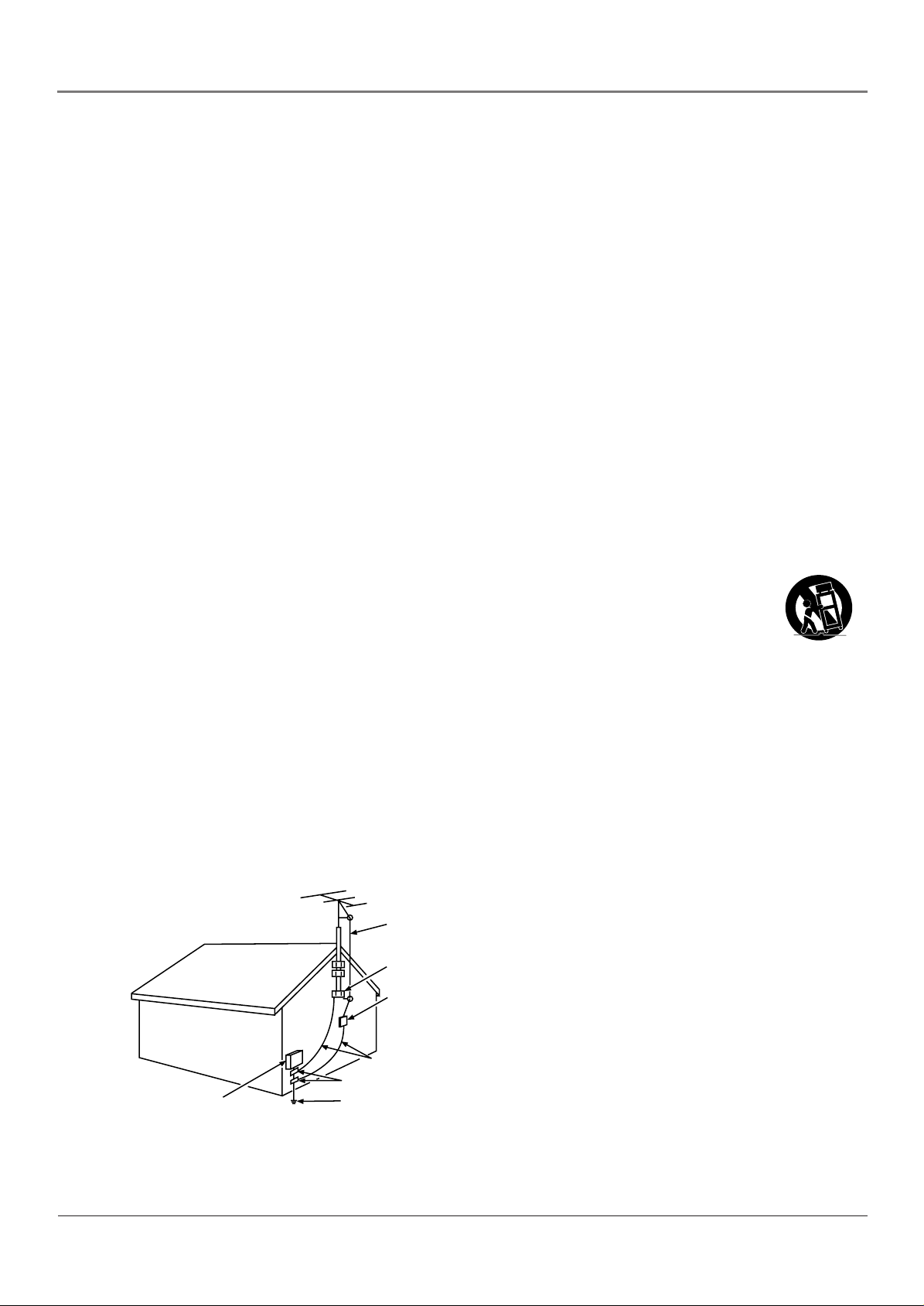
15. If an outside antenna or cable system is connected to the product, be sure the antenna or cable system is grounded
so as to provide some protection against voltage surges and built-up static charges. Section 810 of the National
Electrical Code, ANSI/NFPA No. 70-1984 (Section 54 of Canadian Electrical Code, Part 1) provides information
with respect to proper grounding of the mast and supporting structure, grounding of the lead-in wire to an
antenna-discharge unit, size of grounding conductors, location of antenna-discharge unit, connection to grounding
electrodes, and requirements for the grounding electrode. See following example.
ANTENNA
LEAD IN
WIRE
GROUND CLAMP
ANTENNA
DISCHARGE UNIT
(NEC SECTION 810-20)
GROUNDING CONDUCTORS
(NEC SECTION 810-21)
GROUND CLAMPS
ELECTRIC SERVICE
EQUIPMENT
POWER SERVICE GROUNDING
ELECTRODE SYSTEM
(NEC ART 250, PART H)
i
Page 4

This page intentionally left blank
Page 5

Table of Contents
Important Safety Instructions ........................................................................................... i
Chapter 1: Connections and Setup
Things to Consider Before You Connect .........................................................................3
Protect Against Power Surges ...................................................................................3
Protect Devices from Overheating ............................................................................3
Position Cables Properly to Avoid Audio Interference ............................................3
Use Indirect Light ........................................................................................................3
Connection Illustrations .............................................................................................3
Check Supplied Parts ..................................................................................................3
Attach the Base ................................................................................................................. 4
HDTV Information ............................................................................................................. 4
Choose Your Connection .................................................................................................. 4
Y Pb/Cb Pr/Cr Connection ......................................................................................... 5
Audio/Video Input and Output Connection .............................................................6
DVI Connection ...........................................................................................................7
Connecting to a Personal Computer ......................................................................... 8
Setting Up Your TV ........................................................................................................... 8
Plug in the TV .............................................................................................................8
Put Batteries in the Remote ....................................................................................... 8
Turn on the TV ............................................................................................................8
Completing the On Screen Setup ....................................................................................9
Choose the Menu Language ..................................................................................... 9
Choose the Signal Type .............................................................................................. 9
Complete Channel Search ..........................................................................................9
What to Expect ........................................................................................................... 9
Explanation of Jacks ....................................................................................................... 10
The Buttons on the Remote Control .............................................................................. 12
Chapter 2: Using the TV’s Features
About the Channel Banner ............................................................................................. 13
Parental Controls ............................................................................................................13
US TV Ratings ...........................................................................................................14
Blocking Specifi c Content Themes ..........................................................................15
V-Chip Movie Rating Limit .......................................................................................15
Blocking Canadian V-Chip Ratings .......................................................................... 16
Front Panel Block ......................................................................................................16
V-Chip Unrated/Exempt Block .................................................................................17
Additional Features ........................................................................................................17
MultiTask Audio ........................................................................................................17
Calendar .................................................................................................................... 17
Chapter 3: Using the TV’s Menu System
Menus, On-screen Help, and Control Panels ................................................................. 18
Controls ..................................................................................................................... 18
Picture Menu ...................................................................................................................19
PC Picture Menu .............................................................................................................. 20
Sound Menu .................................................................................................................... 20
Parental Control Menu ................................................................................................... 21
Geometry Menu .............................................................................................................. 21
Time Menu ....................................................................................................................... 21
Preferences Menu ........................................................................................................... 22
Setup Menu .....................................................................................................................22
1
Page 6

Table of Contents
Chapter 4: Other Information
Troubleshooting .............................................................................................................. 24
Care and Cleaning ........................................................................................................... 25
Mounting Your TV to the Wall ....................................................................................... 26
V-Chip Rating Explanations ............................................................................................ 27
US V-Chip Rating System ......................................................................................... 27
Canadian English V-Chip Rating System ................................................................. 27
Canadian French V-Chip Rating System .................................................................. 28
Limited Warranty ............................................................................................................ 29
2
Page 7
Chapter 1: Connections and Setup
Things to Consider Before You Connect
Protect Against Power Surges
• Connect all devices before you plug any of their power cords into the wall outlet or power strip. NEVER plug your
TV into an outlet that is controlled by a wall switch.
• Turn off the TV and/or device(s) before you connect or disconnect any cables.
• Make sure all antennas and cables are properly grounded. Refer to the Important Safety Instructions at the
beginning of the manual.
Protect Devices from Overheating
• Don’t block ventilation holes on any of the components. Arrange the devices so that air can circulate freely.
• Don’t stack devices.
• If you place devices in a stand, make sure you allow adequate ventilation.
• If you connect an audio receiver or amplifi er, place it on the top shelf so the heated air from it won’t fl ow around
other devices.
Position Cables Properly to Avoid Audio Interference
Insert each cable fi rmly into the designated jack.
Use Indirect Light
Don’t place the TV where sunlight or room lighting will be directed toward the screen. Use soft or indirect lighting.
Connection Illustrations
The devices used in the connection illustrations are for representation only. The input jacks and the output jacks on the
back of your devices (VCR, DVD player, etc.,) might look different than those illustrated.
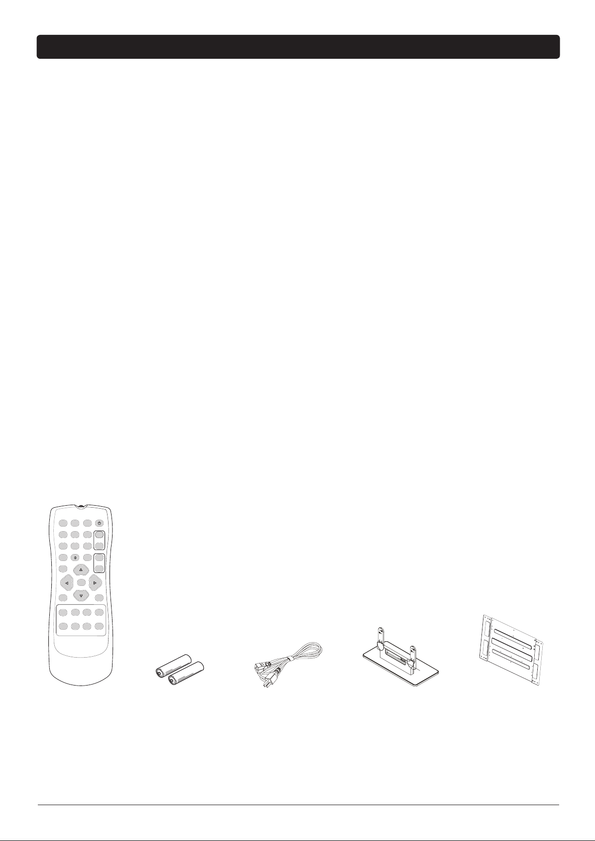
Check Supplied Parts
Check that the following parts were packed with your product.
123
456
789
INPUT MUTE
GO BACK
CLEAR MENU
PRESETS CC INFO FORMAT
SLEEP CALENDAR SOUND PC INPUT
ON•OFF
CH+
CH-
VOL+
VOL-
OK
Remote control 2 AA batteries
Power cord
TV’s base, along with
Wall mount plate
8 screws to attach the
base to TV
Chapter 1 3
Graphics contained within this publication are for representation only.
Page 8
Connections and Setup
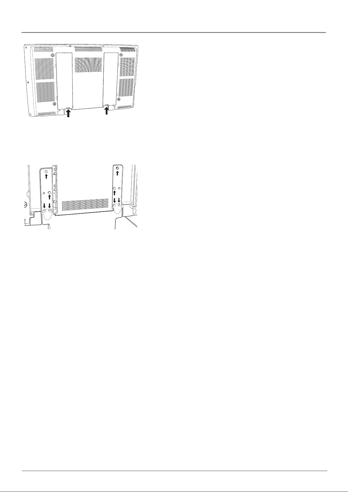
Attach the Base
Your TV comes shipped without the base attached so that you can
choose to mount your TV either to its base or to a wall. If you want
to mount your TV to the wall, don’t attach the base and instead
follow the instructions on page 26. To attach the base, follow these
instructions.
1. Find a strong elevated surface that is soft, fl at, and very clean.
Remove the two jack covers to attach the base.
2. Locate the base and screws.
3. If necessary, remove the two jack panel covers by pushing up on
4. Use a screwdriver to attach the screws into the four holes on each
5. You might want to leave the covers off until you’ve connected
Make sure the surface doesn’t have anything on it that can scratch
the TV screen. Place the TV facedown, towards the edge of the
surface so that when you attach the base it won’t rest on the
surface.
the tabs and pulling the covers out carefully.
side of the TV’s base as the arrows indicate on the base.
devices to your TV. Go to pages 5-8 for information on connecting
your TV.
When you’ve connected devices to the jacks, cables can be
conveniently placed in the groove at the bottom of the jack panels
and the covers fi t back in place over the cables.
Attach the screws into the four holes on each
side of the TV’s base.
HDTV Information
Your LCD TV is a high-defi nition monitor, which means it is capable of receiving high
defi nition TV programs. You’ll need a separate HDTV receiver or tuner to connect to your TV
using one of the inputs that supports a high-resolution signal. Go to page 7 for an example.
If you’re connecting an antenna to the receiver or tuner, visit www.antennaweb.org to get help
deciding what type of antenna to use to receive the local digital channels available to you. By
entering where you live, this mapping program tells you what local analog and digital stations
are available using a certain antenna.
Choose Your Connection
There are several ways to connect your television, depending on the devices you want to
connect and the quality of the signal you want to achieve. It’s important to remember the
different degrees of picture improvement for comparison. The DVI™ and Y Pb/Cb Pr/Cr
(component) jacks are considered excellent; S-Video is very good; Video (composite) jacks are
considered good; while the Tuner (Antenna or Cable) connection is fair.
The following are examples of some ways to connect your TV. Choose the connection which is
best for you.
DVI is a trademark of DDWG (Digital Display Working Group).
4 Chapter 1
Page 9
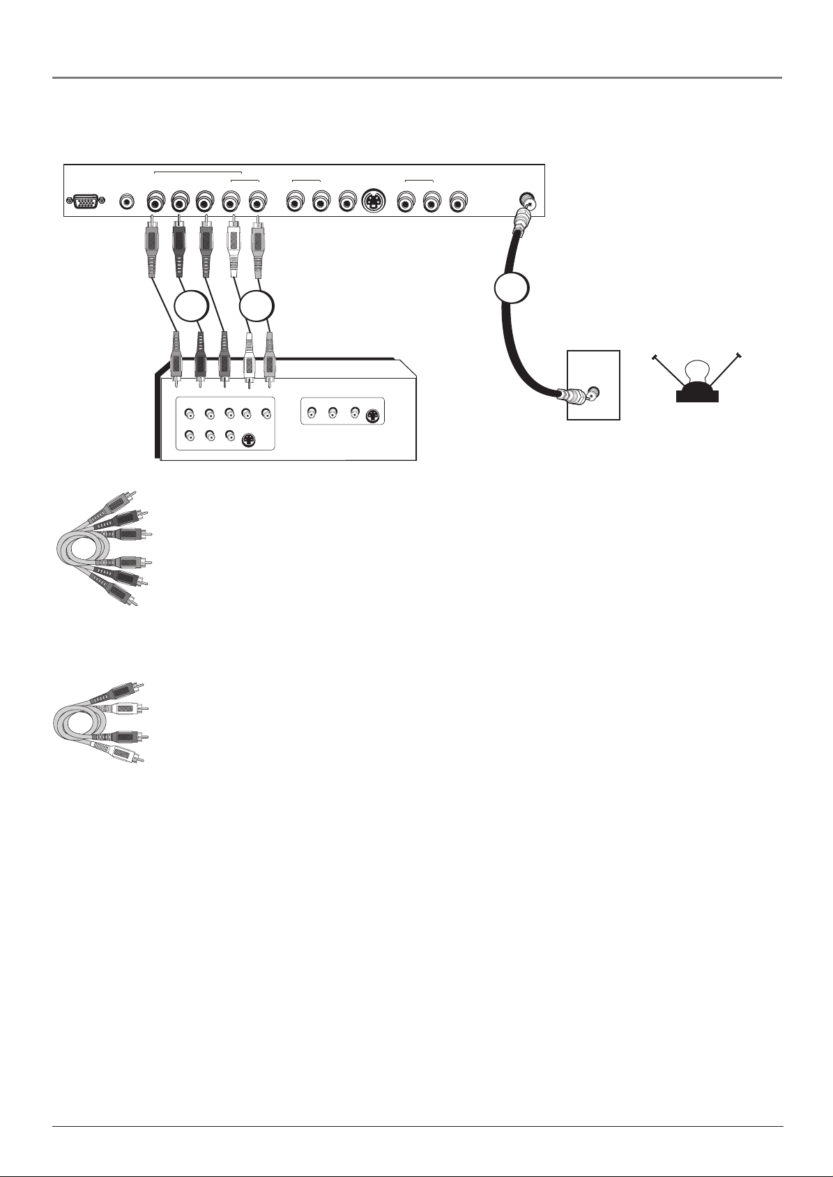
Y Pb/Cb Pr/Cr Connection
Connections and Setup
TV right back panel
VGA
VGA
AUDIO YPb/CbPr/Cr L R R L VID1 R L VID2
Green
Blue
Red
CMPT INPUT
AUDIO
AUDIO1
S-VID
AUDIO2
ANT
1
2 3
CABLE
OUTPUT
COMPONENT VIDEO
VIDEO
L
AUDIO
L
YPbPr
AUDIO
S-VIDEO
R
OUT
Connecting the Device
This connection allows you to connect a device that has Y Pb/Cb Pr/Cr jacks, for example, a
DVD player. The TV’s Component jacks can recognize if the device you’re connecting to is
Y Pb Pr compatible or Y Cb Cr compatible. If the device you are connecting also has S-Video
or composite video, we recommend you use the component video input for better quality.
INPUT
VIDEO
AUDIO
S-VIDEO
L
R
R
IN
OR
OFF-AIR ANTENNA
Component Video
cables (Y Pb Pr) are
color coded- Green,
Blue and Red
Red
White
Audio cables are color
coded- Red= right audio;
white= left audio
Using the example of a DVD player:
1. Connect your cable or off-air antenna to the TV’s ANT input.
2. Connect Y Pb Pr component video cables.
Connect three video grade cables to the Component (CMPT) Y Pb/Cb Pr/Cr jacks on the
back of the TV and to the Y Pb Pr or Y Cb Cr outputs on the DVD player.
3. Connect your audio cables.
Connect the audio (white and red) cables to the R and L AUDIO jacks on the back of the
TV and to the Audio Output jacks on the DVD player.
Viewing the Picture from the Connected Device
The device in this connection is connected to the TV’s Component jacks. To view this device:
1. Plug in the TV (see page 8 for details) and the device, if they aren’t already plugged in.
Turn on the TV and the device you want to view.
2. Press the INPUT button on the remote control to scroll through the Video Input Channels
until you see CMPT displayed in the channel banner.
Chapter 1 5
Page 10
Connections and Setup
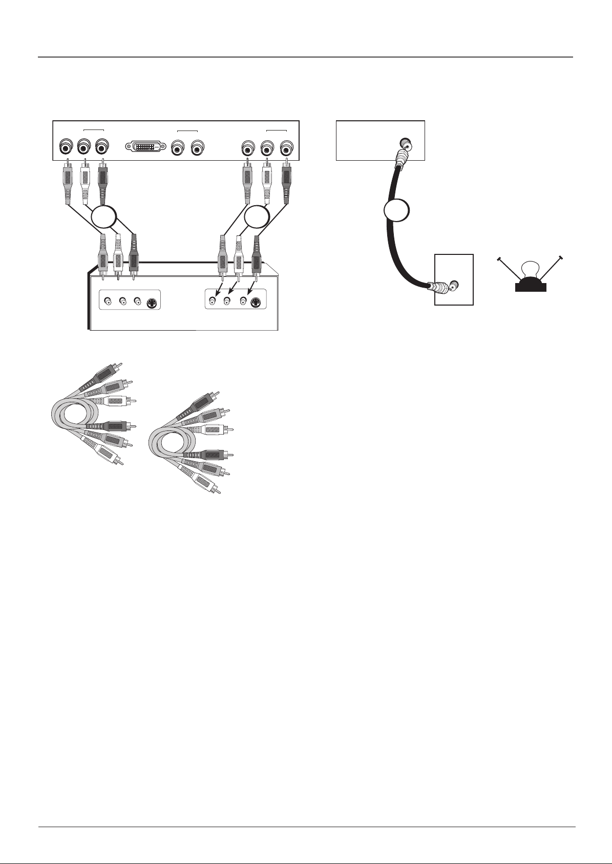
Audio/Video Input and Output Connection
TV left back panel
AUDIO
VID
OUT
L
INPUT
R
VIDEO
DVI
AUDIO
LR
Red
Yellow
White
S-VIDEO
IN
AUDIO
LVID3LR
R
OUTPUT
VIDEO
AUDIO
LR
TV right back panel
AUDIO3
23
S-VIDEO
OUT
ANT
1
CABLE
OR
OFF-AIR ANTENNA
Connecting the Device
This connection allows you to connect a device such as a VCR that has
audio/video inputs and outputs. Connecting to the TV’s output allows
you to record programs.
Use one set of composite audio/video
cables to connect to the TV’s input;
another set to connect to the TV’s output.
Composite cables are color codedYellow= video; Red= right audio; white=
left audio
Using the example of a VCR:
1. Connect your cable or off-air antenna to the TV’s ANT input
on the right back panel.
2. Connect composite audio/video cables to the TV’s input.
Connect composite audio/video cables to the TV’s Input 3 jacks (L
and R AUDIO3, and VID3) and to the VCR’s audio/video outputs.
3. Connect composite audio/video cables to the TV’s output.
Connect composite audio/video cables to the TV’s Audio/Video
Output jacks (L and R AUDIO, and VID OUT) and to the VCR’s
audio/video input.
Viewing the Picture from the Connected Device
The device in this connection is connected to the Input 3 jacks. To
view this device:
1. Plug in the TV (see page 8 for details) and the device, if they aren’t
already plugged in. Turn on the TV and the device you want to
view.
2. Press the INPUT button on the remote control to scroll through the
Video Input Channels until you see VID3 in the channel banner.
6 Chapter 1
Page 11
DVI Connection
TV left back panel
AUDIO
VID
OUT
L
Connections and Setup
R
DVI
AUDIO
LVID3LR
R
AUDIO3
DVI cable
Red
White
Audio cables are color
coded- Red= right audio;
white= left audio
2
DVI Out
R
Audio Out
3
L
Y
Video Out
Cable
Pb
Pr
CABLE
OR
OFF-AIR ANTENNA
1
Connecting the Device
A DVI connection allows you to connect a device that has high-defi nition capability.
Note: The DVI jack is not intended to be used with a computer.
Using the example of an HD receiver:
1. Connect your cable and/or off-air antenna to the HD receiver’s Cable input.
2. Connect a DVI cable to the TV’s DVI input.
Connect a DVI cable to the TV’s DVI input jack and to the HD receiver’s DVI output.
3. Connect composite audio cables to the TV’s DVI audio inputs.
Connect audio cables to the TV’s DVI R and L AUDIO jacks and to the HD receiver’s audio
outputs.
Viewing the Picture from the Connected Device
The device in this connection is connected to the DVI jacks. To view this device:
1. Plug in the TV (see page 8 for details) and the device, if they aren’t already plugged in.
Turn on the TV and the device you want to view.
2. Press the INPUT button on the remote control to scroll through the Video Input Channels
until you see DVI in the channel banner.
Note: If you’re connecting a receiver to the DVI jack, all necessary information is
transferred from the receiver to the TV. Therefore, there is no need to make adjustments
in the Main menu.
Chapter 1 7
Page 12

Connections and Setup
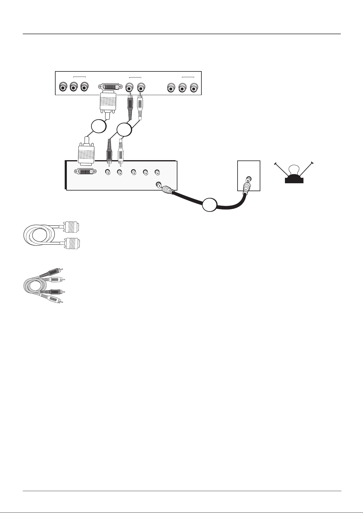
Connecting to a Personal Computer
A. Use a 15-pin monitor cable to connect your TV to a PC. Connect one end of the 15-pin
monitor cable to the VGA jack on the TV and the other end to the PC’s video output.
Note, if your PC’s video output is not 15 pin, you will need an adapter that can connect
to a 15-pin monitor cable.
B. Use a 3.5 mm stereo mini pin cable (sometimes referred to as 1/8” stereo mini pin) to
connect the audio. Connect the 3.5 mm end of the audio cable to the VGA AUDIO jack
on the back of the TV. Connect the other end to the Audio Output jack on the PC.
Notes: The maximum panel resolution is 1366 x 768. Be sure to set your PC to the
correct monitor output setting.
The MultiTask Audio™ feature allows you to listen to the sound from the TV while the PC
is connected. Go to page 17 for more information.
Viewing the PC
1. Plug in the TV (see the following section for details) and the PC, if they’re not already
plugged in. Turn on the TV and the PC.
2. Press the PC INPUT button on the remote control.
Setting Up Your TV
There are several steps you need to follow before you can turn on the TV. Follow the
instructions below to setup and turn on your TV.
Plug in the TV
Plug the end of the cord into the back of the TV. Plug the other end of the power cord into
an appropriate wall outlet. Be sure to insert the plug completely. Do not plug into an outlet
controlled by a light switch.
Put Batteries in the Remote
• Remove the battery compartment cover from the back of the remote by pushing down on
and sliding off the cover.
• Insert 2 fresh “AA” batteries. Make sure the polarities (+ and -) match the diagram in the
battery compartment.
• Replace the cover.
Turn on the TV
The fi rst time you turn on your TV you need to turn on the main power to the TV by pressing
the Power button on the TV’s front panel. Then press the ON/OFF button on the TV or
ON•OFF button on the remote to power on the TV.
8 Chapter 1
Page 13

Connections and Setup
Completing the On Screen Setup
There are several options you might need to set up in order for your TV to work properly. The
fi rst time you turn on your TV, the SETUP screen appears with Language highlighted. Follow
the instructions below to complete the setup for your TV.
MAIN MENU
MAIN MENU
Language English...
Ch. Setup ...
List & Labels ...
Closed Caption ...
Fav. Channels ...
Current Year 2005...
Current Month March...
Current Date 16...
NAVIGATE ▼ ▲ SELECT MAIN MENU
Signal Type Cable...
Auto Search OK...
NAVIGATE ▼ ▲ START OK / SETUP MENU
SETUP
CH. SETUP
▼
▼
▼
▼
MENU
MENU
Choose the Menu Language
Select your preferred language for the menu system.
1. The default language is English. To select French or Spanish, press
the right arrow button.
2. Press the down arrow button on the remote to highlight Ch. Setup.
Choose the Signal Type
In order for your TV to search for channels, you need to make sure
your signal source is set correctly.
1. With Ch. Setup highlighted, press the right arrow button to display
the CH. SETUP menu.
2. By default, the signal type is set to Cable. Leave the signal type set
to Cable if your TV is receiving its signal from cable. If your TV is
receiving its signal from an off-air antenna, press the right arrow
button again to change the option to Antenna.
3. Press the down arrow button to highlight Auto Search.
MAIN MENU
Signal Type Cable...
Auto Search OK...
CH. SETUP
Complete Channel Search
To search for all channels viewable through your antenna or cable TV
system:
1. With Auto Search highlighted, press the OK button.
Note: Depending on the number of channels you receive, it
may take several minutes for the channel search to fi nish.
NAVIGATE ▼ ▲ START OK / SETUP MENU
▼
▼
MENU
2. When the search is complete, you might want to change your
channel list. Go to Chapter 3 for instructions.
If you don’t want to change your channel list, the initial setup
is complete and you can press CLEAR to exit. The other setup
options are explained in Chapter 3.
What to Expect
You might notice as you change channels while using an HD receiver, the size on screen
appears different. Analog channels are sent in a 4:3 format, which can’t fi ll a 16:9 screen like
your TV. Most digital channels are sent in a 16:9 format which do fi ll your screen, but not
always. It depends on how the station is formatting the video. Press the FORMAT button on
your remote to see the different formats available.
Chapter 1 9
Page 14

Connections and Setup
Explanation of Jacks
This section describes the jacks and cables you might use to make connections. There are
several ways to connect devices to your TV.
Back Panel (right)
VGA Connect your computer to this jack using a 15 pin D-sub cable.
VGA AUDIO (Stereo mini jack) Use to obtain sound when a PC is connected to the VGA
jack. Use a 3.5 mm stereo mini pin cable (sometimes referred to as 1/8” stereo mini pin) to
connect a PC to your TV. Go to page 8 for more information.
CMPT (Component) INPUT
• Y Pb/Cb Pr/Cr For connection of devices that have component output jacks (Y Pb Pr),
such as an HD receiver, or DVD player. The TV’s Component jacks can recognize if the
device you’re connecting to is Y Pb Pr compatible or Y Cb Cr compatible.
The Y Pb/Cb Pr/Cr jacks provide excellent picture quality because the video is separated
into three separate parts.
• AUDIO L and R Use the left and right audio jacks when connecting to the Component
video inputs. The right connector is usually red; the left connector is usually white.
Composite Input 1
• AUDIO R and L Use the AUDIO1 right and left audio jacks when connecting to the VID1
input jack. The right connector is usually red; the left connector is usually white.
• VID1 Provides composite video connection. The video connector is usually yellow.
S-VID The S-Video (super video) jack provides better picture quality than the regular video
jack because the color (chrominance, also called chroma) part of the signal is separated from
the black and white (luminance) part of the picture.
If a device you’re connecting to your TV (like a DVD player) has an S-VIDEO and a VIDEO
jack, connect the DVD player to the TV with an S-Video cable (not provided) for better picture
quality.
Note: Remember to connect the left and right audio cables to the AUDIO1 In jacks
because the S-Video cable carries only the picture signal, not the sound.
Composite Input 2
AUDIO R and L Use the AUDIO2 right and left audio jacks when connecting to the VID2
input jack. The right connector is usually red; the left connector is usually white.
VID2 Provides an additional composite video connection. The video connector is usually
yellow.
ANT Lets you connect a coaxial cable to receive the signal from the antenna, cable, or cable
box.
Back Panel (left)
AUDIO/VIDEO OUTPUT Connect a VCR to record programs. You must leave the TV on the
same channel you are recording.
• VID OUT Provides composite video connection and connector is usually yellow.
• AUDIO L and R Use the Audio left and right audio jacks when connecting to the VID
OUT jack. The right connector is usually red; the left connector is usually white.
Note: When recording from this output, remember to tune to the channel you want to record.
10 Chapter 1
Page 15

Connections and Setup
DVI (Digital Visual Interface) Provides an uncompressed digital interface designed to deliver
digital video in its native format. It supports the overlay of high-resolution graphics used by
some program guides and interactive devices.
Note: The DVI jack is not intended to be used with a computer.
• AUDIO R and L Use the Audio right and left audio jacks when connecting to the DVI
jack. The right connector is usually red; the left connector is usually white.
Composite Input 3
• VID3 Provides a third optional composite video connection. The video connector is
usually yellow
• AUDIO L and R Use the Audio 3 right and left audio jacks when connecting to the VID3
input jack. The right connector is usually red; the left connector is usually white.
Front Panel Buttons
If you can’t locate your remote, you can use the buttons located underneath the front panel of
your TV to operate many of the TV’s features.
ON/OFF Turns on or off the TV after you’ve turned on the main power by pressing the
Power button.
MENU Brings up the menu system.
VOL – Decreases the volume. In the menu system, it points left to items and adjusts menu
controls.
VOL + Increases the volume. In the menu system, it points right to items and adjusts menu
controls.
CH – Scans down through the channel list. In the menu system, it points down to items and
adjusts menu controls.
CH + Scans up through the current channel list. In the menu system, it points up to items and
adjusts menu controls.
(Power) Turns the main power to the TV on or off.
Note: If you use the Front Panel Block feature, the front panel buttons no longer provide
access to the menus. Go to Chapter 2 for more information.
Side Panel
(Headphone) Allows you to connect headphones to listen to the sound coming from the
TV.
Note: When you plug in headphones, the TV’s internal speakers are automatically
turned off.
Chapter 1 11
Page 16

Connections and Setup
The Buttons on the Remote Control
12 3
45 6
78 9
INPUT MUTE
GO BACK
CLEAR MENU
PRESETS CC INFO FORMAT
ON•OFF
CH+
CH-
VOL+
VOL-
OK
Arrow buttons Highlights different items in the TV menu and
adjusts the menu controls.
(0-9) Number buttons Enter channel numbers and password
settings directly through the remote control.
CALENDAR Displays the calendar of the current month and year.
Make sure you’ve set the date correctly in the SETUP menu.
CC Brings up the Closed Caption menu.
CH + or CH - Scans up or down through the current channel list.
CLEAR Removes any menu or display from the screen and returns
you to normal viewing.
GO BACK Returns you to the previous channel.
SLEEP CALENDAR SOUND PC INPUT
FORMAT Changes the aspect ratio: 4:3, 14:9 Zoom, 16:9 Zoom,
Cinerama, 16:9 Subtitles, and 16:9 Widescreen.
INFO Brings up the channel banner; press again to clear the screen.
INPUT Toggles through the available video input channels-
VID1/S-VID, VID2, VID3, CMPT, VGA, DVI, and current channel.
MENU Brings up the menu system.
MUTE Reduces the TV’s volume to its minimum level. Press again to
restore the volume.
OK When in the menu system, changes highlighted items to another
option.
ON•OFF Turns the TV on and off.
PC INPUT Switches to the PC Input (VGA).
PRESETS Toggles through the brightness settings of the picture:
Personal, Soft, Natural, and Bright.
SLEEP Sets the TV to turn off. Each time you press SLEEP the clock
adds 5 minutes (up to 120 minutes). To cancel, press CLEAR.
SOUND Toggles through the sound modes: Concert, Stereo, Cinema,
News, Surround, and Personal. In PC mode, switches to the TV’s
audio.
VOL – or VOL + Decreases or increases the TV’s volume.
12 Chapter 1
Page 17

Chapter 2: Using the TV’s Features
MAIN MENU
VGA
About the Channel Banner
The Channel Banner appears when you press the INFO button on the
remote or the button corresponding to the function. The following list
describes the items on the Channel Banner screen (left to right and top
to bottom). Other displays that are not shown are self-explanatory.
The icons change appearance to show the item’s status or availability.
Sleep 20 min.
Volume 38
VGA Displays the current input you’re viewing. Displays the current
channel when you’re watching TV.
Mute Icon Displays when you mute the sound.
Sleep 20 min. Corresponds to the SLEEP button. Shows how much
time is set before the TV turns off.
Volume Displays the level of the volume when you press the
VOL + or - button. The volume level has 100 steps.
PAR. CONTROL
US TV Ratings ...
US Movie Ratings ...
CA English Ratings ...
CA French Ratings ...
Front Panel Block
Unrated/Exempt Block...
NAVIGATE
▼ ▲
▼
SELECT MAIN MENU
▼
MENU
Parental Controls
The choices in the Parental Control menu involve software inside
your TV (referred to as V-Chip) which lets you block TV programs
and movies based on violence, sex, or other content you may believe
children should not view. Once you block programs, you or other
adults can unblock programs by entering a password.
By default, the software inside your TV is turned “off,” so if you don’t
want to use this feature, you can just ignore it.
The fi rst time you enter the Parental Control menu, a password screen
appears. Enter the default password 1111. If you want to change your
password, highlight Change Pwd. and press OK. Then use the number
buttons to enter the on-screen information and press the down arrow
button to highlight the next entry and a confi rmation screen appears
when it’s complete. Once you’ve entered your password, press OK to
continue.
How V-Chip Works
The V-Chip software reads a code that most broadcasters send with programs. That code
tells the software the program’s age-based rating (TV-MA, TV-14, etc.) and content themes
[(Violence (V), Adult Language (L), etc.)]. If you have blocked the rating and/or content themes
that the program contains and you tune to a program whose rating exceeds the rating limit you
set, you will receive a message telling you that the program is not approved for viewing.
Broadcasters are not required to provide content themes, so programs received with no content
themes will only be blocked if you block their age-based rating. You can also block out programs
that have been given a rating of Not Rated, and programs that are considered unrated. The TV
age-based ratings and content themes you can block follow.
Note: The V-Chip USA, Canadian English and Canadian French ratings explanations
are on page 27.
Chapter 2 13
Graphics contained within this publication are for representation only.
Page 18

Using the TV’s Features
MAIN MENU
US TV RATINGS
Status Content
TV-MA View... L S V
TV-14 View... D L S V
TV-PG View... D L S V
TV-G View...
TV-Y7 View... FV
TV-Y View...
NAVIGATE
▼
▼ ▲
VIEW/BLOCK OK P.C. MENU
▼
MENU
US TV Ratings
The US TV Ratings lets you decide which TV programs can and cannot
be viewed. To set TV programming limits:
1. Press MENU to bring up the menu system.
2 Choose the Parental Control icon. Enter the 1111 default password
or the password you chose and press OK to continue.
3. Highlight and press the right arrow to display US TV Rating.
4. Once you get to the US TV Ratings screen, use the up and down
arrow buttons to highlight a rating.
Proceed to the next sections for more details about how to change the
status of TV program ratings.
The US Rating Limit Screen
The following is an example of where items are located within the V-Chip TV Ratings screen.
Rating Field
Lets you select the age-based
rating you want to block or view.
Rating Status Field
Lets you select whether the status
of the age-based rating limit to
the left is View or Block.
MAIN MENU
US TV RATINGS
Status Content
TV-MA View... L S V
TV-14 View... D L S V
TV-PG View... D L S V
TV-G View...
TV-Y7 View... FV
TV-Y View...
NAVIGATE
▼ ▲
▼
VIEW/BLOCK OK P.C. MENU
▼
MENU
Content Themes
Lists the content themes you
can block or view.
Content Status Fields
Displays whether the status of the
content theme is currently Locked
or Unlocked.
Hierarchy of Age-Based Ratings
TV-MA Mature Audience Only
TV-14 Parents Strongly Cautioned
TV-PG Parental Guidance Suggested
TV-G General Audience
TV-Y7 Directed to Children 7 years
and older
TV-Y All Children
Blocking Age-Based Ratings
You can automatically block all program ratings above a specifi ed agebased rating level. For example, if you only want your child to watch
programs that have a TV-G rating and lower (in other words, you want
the child to watch TV-G, TV-Y7, and TV-Y), then you need to block
out higher ratings.
To block programs with higher ratings:
1. First, determine the lowest level rating you don’t want the child to
watch.
2. Highlight the lowest rating you do not want the child to watch. In
the example discussed above, you would highlight TV-PG, since
the highest rating you want the child to watch is TV-G.
3. Press the OK button to toggle between View and Block. The
status for the rating you chose and all higher ratings automatically
change to Block.
4. To lock the settings, exit the Parental Control menu or menu
system and the password screen appears. Enter your password
and press OK. If you exit the menu system without entering your
password, the settings you changed won’t take effect.
14 Chapter 2
Page 19

Using the TV’s Features
Viewing Age-Based Ratings
After you block age-based ratings, you have the option of changing some of the ratings back to
View.
1. Determine which blocked rating you want to view.
2. Use the up and down arrow buttons to highlight the rating with a status of Block.
3. Press the OK button to select View.
4. To lock the settings, exit the Parental Control menu or menu system and the password
screen appears. Enter your password and press OK. If you exit the menu system and
cancel after entering your password, the settings you changed won’t take effect.
MAIN MENU
Status Content
TV-MA View... D L S V
TV-14 View... D L S V
TV-PG View... D L S V
TV-G View...
TV-Y7 View... FV
TV-Y View...
NAVIGATE
US TV RATINGS
▼
▼ ▲
OK P.C. MENU
▼
Content Themes
D Sexually explicit dialogue
L Adult language
S Sexual situations
V Violence
FV Fantasy Violence
MENU
Blocking Specifi c Content Themes
You can block programs based on their content. (Content is
represented by the D, L, S, V and FV on your screen.) When you block
a content theme for a particular rating, you automatically block that
content theme for higher rated programs as well.
To block program content:
1. Determine the content themes you want to block.
2. Press the down arrow button to select the age-based rating you
want to change.
3. Press the right arrow button to highlight a particular content
theme.
4. Press the OK button to change its status to the lock icon, or
block. (In the example to the left, you block the language (L)
corresponding with TV-14).
Notes: Broadcasters are not required to provide content
themes or age-based ratings.
5. Lock the settings as described above or the changes won’t take
effect.
To view content themes after you’ve locked them, follow the same
steps to unlock. Then lock Parental Controls to save your changes.
MAIN MENU
NR View...
X Block...
NC-17 View...
R View...
PG-13 View...
PG View...
G View...
NAVIGATE ▼ ▲ OK P.C. MENU
US MOVIE RATINGS
▼
▼
MENU
V-Chip Movie Rating Limit
You set movie rating limits by blocking movies rated above a
specifi ed rating. How to block movie ratings and view movie ratings is
explained in the next two sections.
To access the V-Chip Movie Rating menu:
1. Press MENU on the remote control.
2. Press the down arrow button to select the Parental Control icon.
3. Select US Movie Ratings.
Chapter 2 15
Page 20

Using the TV’s Features
Blocking Movie Ratings
If you only want your child to watch movies that have a PG rating and lower (in other words,
movies rated PG and G), then you could automatically block out all other movies with higher
ratings.
To block movies:
1. Highlight the rating that is the lowest rating you don’t want the child to watch. (In the
example above, you would highlight the rating status button corresponding to PG-13, since
the highest rating you want the child to watch is PG.)
2. Press the OK button to change from View to Block. All higher ratings automatically change
to Block.
3. To lock the settings, exit the Parental Control menu or menu system and the password
screen appears. Enter your password and press OK. If you exit the menu system without
entering your password, the settings you changed won’t take effect.
Note: Some movies may be given a Not Rated (NR) rating. After blocking movie ratings,
you must unlock NR separately in order to view movies with an NR rating.
To view movie ratings after you’ve locked them, follow the same steps to unlock. Then lock
Parental Controls to save your changes.
MAIN MENU
18 ans+ View...
16 ans+ View...
13 ans+ View...
8 ans+ View...
G View...
CA FRE NCH
Blocking Canadian V-Chip Ratings
If you receive Canadian programs you can block Canadian English and
French V-Chip by ratings only. When you block a particular rating, you
automatically block the higher rated programs as well.
To block Canadian English and French program ratings:
1. Press the MENU button and select the Parental Control icon.
NAVIGATE
▼ ▲
VIEW/BLOCK OK P.C. MENU
MENU
2. Highlight CA English Ratings or CA French Ratings and press OK.
MAIN MENU
18+ View...
14+ View...
PG View...
G View...
C8+ View...
C View...
CA ENGLISH
3. Determine the rating you want to block.
4. Press the down arrow button to scroll to the rating you want to
change.
5. Press the OK button to change its status to Block. All ratings above
the one you selected change to Block.
6. Lock the settings as described above or the changes won’t take
NAVIGATE
▼ ▲
VIEW/BLOCK OK P.C. MENU
MENU
effect.
To view Canadian ratings after you’ve locked them, follow the same
steps to unlock. Then lock Parental Controls to save your changes.
Front Panel Block
Selecting this option lets you block (disable) or unblock (enable) the TV’s front panel buttons.
The remote still tunes to any channel. Front Panel Block can:
• Keep children from watching TV when the parent is not present.
• Keep young children from playing with the buttons on the TV.
(When using this as a Parental Control method, you should remove access to any remote that is
capable of operating the television while you have the front panel blocked.)
Don’t forget to lock the TV after you disable Front Panel Block (box has check mark). If you do
not, the front panel block will not take effect.
Notes: If power to the TV is lost for more than an hour, the buttons become unblocked.
To temporarily override front panel block, make sure no menus are displayed on-screen.
Simultaneously press and hold the MENU button on the TV’s front panel and CLEAR on
the remote for approximately 10 seconds.
16 Chapter 2
Page 21

Using the TV’s Features
V-Chip Unrated/Exempt Block
The V-Chip Unrated/Exempt option lets you decide if programs that the V-Chip recognizes as
unrated can be viewed. Unrated TV programs may include news, sports, political, religious,
local and weather programs, emergency bulletins, public announcements, and programs
without ratings. The V-Chip Unrated/Exempt option applies to both US and Canadian unrated
programs and Canadian programs rated E.
View All unrated programs are available.
Block All unrated programs are not available.
Note: You must remember to lock Parental Controls for rating limits to take effect.
Press the down arrow to highlight Unrated/Exempt. Then press the right arrow to toggle
between View and Block.
Additional Features
There are additional features available by using the remote control.
MultiTask Audio
The MultiTask Audio feature allows you to listen to the sound from the TV while the PC is
connected. Tune to the program on the TV you want to listen to. Switch to the PC input by
pressing the PC INPUT button on the remote. Press the SOUND button to hear the program’s
audio. Press SOUND again to turn off the program’s audio. To listen to a different program,
press the GO BACK button to return to the TV input. Then change the channel until you fi nd
the new program you want to listen to and go back to the PC input as previously described.
Calendar
Use the CALENDAR button on the remote to display the current month and year page. To
display a different month use the up and down arrow buttons; to display a different year use
the left and right arrow buttons.
There are also more features available through the menu system, such as:
• Picture adjustments
• Sound adjustments
• Time settings
• Auto Volume Level
Go to the next chapter for more details.
Chapter 2 17
Page 22

Chapter 3: Using the TV’s Menu System
0
Menus, On-screen Help, and Control Panels
This section explores the menus of your TV, beginning with some information on using menus
and control panels. Each menu is outlined and detailed to help you get the most from your TV.
The Parental Control menu is discussed in the Features chapter.
MAIN MENU
PICTURE
Brightness 50
Contrast 50
Saturation 50
Sharpness 50
Tint 50
Backlight 50
Color Warmth Cool... 5
Picture Preset Soft...
NAVIGATE ▼ ▲ ADJUST MAIN MENU
▼
▼
MENU
1. Press the MENU button.
2. Use the up and down arrow buttons to highlight the icons on
the left. The corresponding menu options with the icon you’ve
highlighted are displayed on the right. The name of the menu is
displayed at the top of the menu screen.
3. Press the right arrow button to access the menu of the icon you’ve
highlighted. Then use the up and down arrow buttons to move to
a different option within the menu. Also, use the text at the bottom
of each screen for help.
4. To highlight a different icon on the left, press the MENU button
on the remote, then use the up or down arrow button to select a
different icon.
Descriptions of each menu are discussed in the order the icons appear.
If a PC is connected to the TV, press the PC INPUT button on the
remote to display the VGA Input. Then press the MENU button to
display the specifi c PC menus.
Exiting a menu
There are two ways to exit a menu:
• Press MENU until on-screen menus disappear.
To access the menu system:
• Press CLEAR. The on-screen displays are cleared from the screen
and you return to TV viewing.
Control s
Controls let you adjust the default settings of your TV. You can choose a setting, enter a
number, or adjust a level such as tint or brightness. There are four types of controls: sliders,
choice lists, numeric entries, and option lists.
Contrast
Auto Vol. Level
50
Sliders
Sliders are used to select a specifi c point of a control that has
continuous levels. To make adjustments:
1. Press the up or down arrow button to select the slider control for
the feature you want to adjust.
2. Press the left or right arrow button to adjust the indicator on the
slider.
Choice Lists
Check boxes allow you to turn on or off an option. Press the left or
right arrow button to turn on or off an option.
18 Chapter 3
Graphics contained within this publication are for representation only.
Page 23

Using the TV’s Menu System
_ _
_ _
0
MAIN MENU
Time
_ _
: _ _
am
Numeric Entries
Numeric entry fi elds are used to enter numbers and passwords. Use
the number buttons on the remote to enter the information.
1. Use the up or down arrow button to highlight the fi eld.
2. Use the number buttons to enter information and the left and right
arrow buttons to move to the next entry, if necessary.
Sound Mode
Stereo...
Option Lists
An option list cycles through at least two or more choices. Press the
left or right arrow button to select the next entry in the choice fi eld.
PICTURE
Brightness 50
Contrast 50
Saturation 50
Sharpness 50
Tint 50
Backlight 50
Color Warmth Cool... 5
Picture Preset Soft...
NAVIGATE ▼ ▲ ADJUST MAIN MENU
▼
▼
MENU
Picture Menu
The Picture menu displays fi ve slider controls for adjusting the way
the picture looks.
To access the Picture menu press the MENU button on the remote
control. The Picture icon is highlighted and the following menu
options appear.
Brightness Adjusts the brightness of the picture.
Contrast Adjusts the difference between the light and dark areas of
the picture.
Saturation Adjusts the richness of color.
Sharpness Adjusts the crispness of the edges in the picture.
Tint Adjusts the balance between the red and green levels.
Backlight Press the right arrow button to adjust the level of light,
depending on room lighting.
Color Warmth Automatically adjusts the color temperature of
the picture. Press the right arrow button to scroll through the color
adjustments: Cool for a more blue palette of picture colors; Normal;
and War m for a more red palette of picture colors.
Picture Preset Toggles through the picture preset settings: Soft,
Natural, Bright, and Personal.
When you change the options of the picture, the picture preset
changes to Personal.
Chapter 3 19
Page 24

Using the TV’s Menu System
MAIN MENU
PICTURE
Brightness 50
Contrast 50
Backlight 50
Color Warmth Cool...
Picture Preset Soft...
NAVIGATE ▼ ▲ ADJUST MAIN MENU
▼
▼
MENU
PC Picture Menu
These adjustments apply to the VGA Input when a PC is connected to
your TV. To access the PC Picture menu:
1. Press the PC INPUT button on the remote control.
2. Press MENU on the remote control. The following menu options
appear.
Brightness Adjusts the brightness of the picture.
Contrast Adjusts the difference between the light and dark areas of
the picture.
Backlight Press the right arrow button to adjust the level of light,
depending on room lighting.
Color Warmth Automatically adjusts the color temperature of
the picture. Press the right arrow button to scroll through the color
adjustments: Cool for a more blue palette of picture colors; Normal;
and War m for a more red palette of picture colors.
Picture Preset Toggles through the picture preset settings: Soft,
Natural, Bright, and Personal.
When you change the color options of the picture, the picture preset
changes to Personal.
MAIN MENU
SOUND
Auto Vol. Level
Sound Mode News...
SRS WOW
SAP
Balance +54
Speakers Internal...
Hd. Ph. Volume 50
Equalizer ...
NAVIGATE
▼ ▲
▼
SELECT MAIN MENU
▼
MENU
Sound Menu
The Sound menu lets you adjust audio output. To access the Sound
menu, press MENU on the remote, and then select the Sound icon.
Auto Vol. Level (Auto Volume Level) Turn on this feature to reduce
blasts in volume during commercial breaks to create more consistent
audio output.
Sound Mode Press the right arrow button to scroll through the available audio types, which
control the way the sound comes through your speakers: Stereo, Cinema, News, Surround, Concert,
and Personal. The personal setting is saved according to changes you make to Balance and/or the
Equalizer setting.
Note: When Surround is turned on SRS WOW turns on automatically.
Creates a three-dimensional sound while extending the sound range beyond the size of
the speakers. When SRS WOW is turned on, the sound mode changes to Surround.
SAP Plays the program’s audio in a second language, if one is available. SAP audio is broadcast
in mono. SAP is also used to broadcast a program’s audio with descriptions of the video for the
visually impaired.
Note: SAP is not available for video input channels.
Balance Adjusts how much audio (loudness) gets sent to the left and right speakers.
Speakers Allows you to choose Internal if you want to use the internal speakers for sound or
External if you have an external device connected to the AUDIO L/R OUT jacks and want to use
those speakers for sound.
Hd. Ph. (Headphone) Volume Increases or decreases the volume coming from the TV’s
speakers to the Headphone jack.
Equalizer Lets you adjust the audio frequency settings: 100Hz, 500Hz, 1.5kHz, 5kHz, and 10kHz.
WOW, SRS and symbol are trademarks of SRS Labs, Inc.
WOW technology is incorporated under license from the SRS Labs, Inc.
20 Chapter 3
Page 25

Using the TV’s Menu System
Parental Control Menu
The Parental Control menu was explained in Chapter 2. Go to page 13 for more information.
MAIN MENU
MAIN MENU
GEOMETRY
Auto Adjust OK
V.Position
H.Position
Phase
Clock
NAVIGATE ▼ ▲ ADJUST MAIN MENU
▼
▼
MENU
Geometry Menu
These adjustments apply to the CMPT and VGA inputs:
Auto Adjust Adjusts the position of the picture automatically.
V. Position (Vertical Position) Adjusts the picture’s position upward
or downward.
H. Position (Horizontal Position) Adjusts the picture’s position left or
right.
Phase Adjusts the picture if there is fl icker of screen letters, color
misalignment, or blurring.
Clock Adjusts the clock sync of the picture.
Sleep Timer Off...
Time 12:35 pm
Wake-Up Timer Once...
Wake-Up Time 06:00 am
Wake-Up Channel 13
Turn-Off Timer Daily...
Turn-Off Time 11:00 pm
Calendar ...
NAVIGATE ▼ ▲ OK am/pm ADJUST MAIN MENU
TIME
▼
▼
MENU
Time Menu
Sleep Timer A one-time event that is used to set the TV to turn off
at a specifi c time.
Time Lets you set the time. If it is 8:25, for example, you must fi rst
press the number 0 on the remote, then number 8, then 2 and then 5.
Press the OK button to choose between am and pm. To reset the time,
press the left or right arrow.
Wake-Up Timer Lets you set the TV to turn itself on. Choose Once,
Daily, or None.
Wake-Up Time Lets you set the time you want the TV to turn itself
on. Follow the same instructions as setting the Time.
Wake-Up Channel Lets you choose the channel you want the TV to
tune to when it turns on from the Wake-Up Timer.
Turn-Off Timer Lets you set the TV to turn itself off after it turns on
from the Wake-Up Timer. Choose Once, Daily, or None.
Turn-Off Time Lets you set the time you want the TV to turn itself
off. Follow the same instructions as setting the Time.
Calendar Displays the current month and year page according
to the month, year and date you set in the Setup menu. To display
a different month, use the up and down arrow buttons; to display a
different year, use the left and right arrow buttons. Use the CALENDAR
button for immediate display of the Calendar.
Chapter 3 21
Page 26

Using the TV’s Menu System
MAIN MENU
MAIN MENU
Auto Color
Noise Reduction Medium...
Zoom Mode 16:9 Subtitles...
OSD Position Middle...
Film Mode
NAVIGATE ▼ ▲ SELECT MAIN MENU
Language English...
Ch. Setup ...
List & Labels ...
Closed Caption ...
Fav. Channels ...
Current Year 2005...
Current Month March...
Current Date 16...
NAVIGATE ▼ ▲ SELECT MAIN MENU
PREFERENCES
▼
SETUP
▼
▼
▼
MENU
MENU
Preferences Menu
Auto Color Minimizes the fl esh tone variations of the TV’s picture.
Turn on or off depending on your preference.
Noise Reduction Allows you to reduce any type of interference in
the picture. Choose the option which is best for your picture: Low,
Medium or High.
Zoom Mode Allows you to change how the picture is displayed on
your screen: 4:3, 14:9 Zoom, 16:9 Zoom, Cinerama, 16:9 Subtitles, and
16:9 Widescreen.
OSD Position Selects where you want the menu to appear on the
TV.
Film Mode (Also known as 3:2 Reverse Pulldown) Detects and
converts fi lm content for better display with minimal artifacts. If you’re
watching a movie, turn to on (box has check mark).
Setup Menu
Language Select your preferred language for the menus.
Ch. Setup (Channel Setup) Displays options Signal Type and Auto
Search.
Signal Type Choose the type of signal your TV is receiving:
Cable or Antenna. Go to page 9 for more information.
Auto Search Allows the TV to search for channels the signal is
receiving and stores them in the TV’s channel list. Go to page 9 for
more information.
List & Labels Allows you to enter channels you want to delete or
add to your channel list.
Ch. No. (Channel number) Use the number or arrow buttons
to enter the channel number. To enter a one-digit channel, enter
two zeros fi rst. To enter a two-digit channel, enter one zero fi rst.
For example, if you want to add channel 7 to your list, press the
number 0, 0, then press 7.
Ch. Label Allows you to add a six character label, which is
displayed on-screen when you tune to the channel entered in the
Ch. No. Press the 1 or 2 number buttons on the remote to scroll
through the available characters. Continue to press the right arrow
button to highlight the next space to add another character. Press
the left arrow to erase the label.
In List If you’ve entered a channel you want to add to the
channel list, highlight In List and press the right arrow button to
place a check in the checkbox. If you’ve entered a channel you
want to delete from the channel list, press the right arrow button to
uncheck the checkbox.
22 Chapter 3
Page 27

Using the TV’s Menu System
Closed Caption (only available for TV video input channel) Many programs are encoded
with closed-captioning information, which lets you display the audio portion of a program as
text on the TV screen.
Closed captioning is not available on all channels at all times. Only specifi c programs encoded
with closed-captioning information are applicable. The closed caption options are:
CC Setting Choose the way closed captioning information is shown on the screen.
On Captioning information always appears, when available.
Off No captioning information displayed.
On When Mute Displays captioning information, when available, whenever the
TV’s sound is muted by pressing the MU TE button. The captioning information is not
displayed when the sound is not muted.
CC Mode Choose which captioning mode is used for displaying captioning information.
If you are unsure of the differences among the modes, you may prefer to leave the closed
captioned mode set to CC1, which displays complete text of the program in the primary
language in your area.
CC Displays information at any position on the screen. It overlays the text on top of
the picture as it is received.
Text Displays information at one particular position (such as the bottom third) on the
screen. You cannot see the picture underneath the text.
Choose between these closed caption modes or sources:
•CC1 and Text1 are the primary caption and text services. The captioning or text is
displayed in the same language as the program’s dialog.
•CC3 and Text3 serve as the preferred data channels. The captioning or text is often a
secondary language translation, simplifi ed English, or displayed at a slower rate.
•CC2 and CC4, and Text2 and Text4 are rarely available and broadcasters use them
only in special conditions, such as when CC1 and CC3 are not available, or Text1 and
Text3 are not available.
Fav. Channels Lets you set six of your favorite channels in order of preference. Use the
number buttons to enter your channels.
Current Year Lets you set the current year using the arrow buttons.
Current Month Lets you set the current month using the arrow buttons.
Current Date Lets you set the current day using the arrow buttons.
Note: Once you set the current day, month and year, you can press the CALENDAR
button to view the current calendar month and year.
Chapter 3 23
Page 28

Chapter 4: Other Information
Troubleshooting
Most problems you encounter with your TV can be corrected by consulting the following troubleshooting list.
Note for U.S. customers: If you prefer, we can provide you with the name of an Authorized Service
Representative who will visit your home for a fee to install your electronic entertainment system and to instruct
you in its operation. For details about this service, call 1-888-206-3359. For additional assistance while using
your RCA product, please visit www.rca.com.
TV Problems
TV won’t turn on
• Make sure the power has fi rst been turned on by pressing the (Power) button on the TV’s front panel. Then press the ON/
OFF button.
• Make sure the TV is plugged in.
• Check the wall receptacle (or extension cord) to make sure it is “live” by plugging in something else.
• Something might be wrong with your remote control. Press the ON/OFF button on the TV’s front panel. If the TV turns on,
check the remote control solutions on page 25.
• The front panel controls may be locked (disabled). Use the remote control to unlock the front panel controls by selecting the
Front Panel Block in the Parental Control menu and press OK (box won’t have check mark).
Buttons don’t work
• The front panel controls may be locked (disabled). Use the remote control to unlock the front panel controls by selecting the
Front Panel Block in the Parental Control menu and press OK (box won’t have check mark).
• Unplug the TV for two minutes and then plug it back in. Turn the TV on and try again.
TV turns off unexpectedly
• Sleep timer might have been activated. Go to page 12 for instructions.
• Electronic protection circuit may have been activated because of a power surge. Wait 30 seconds and then turn on again. If this
happens frequently, the voltage in your house may be abnormally high or low.
• Unplug TV. Wait fi ve minutes. Plug it in again.
Blank screen
• Make sure the device connected to the TV is turned on.
• Try another channel.
• You might be tuned to another video input channel. Press INPUT until you tune to the TV input.
Sound problems, picture okay
• Maybe the sound is muted. Try pressing the volume up button to restore sound.
• If using S-Video or Y Pb Pr, remember to also connect the device’s left and right audio output jacks to the TV’s AUDIO jacks.
• Make sure the Volume option in the Sound menu is turned up.
• Make sure the Speakers option in the Sound menu is set to Internal.
• Make sure headphones aren’t connected to the headphones jack. If you hear a pop when you turn off or on the TV, this is
normal when the headphones are connected.
Can’t select certain channel
• Channel may be blocked or not approved through the V-Chip.
• If using a VCR, check to make sure the TV/VCR button on the VCR is in the correct mode (press the TV/VCR button on your
VCR).
No picture, no sound but TV is on
• Maybe the signal type is set wrong. Go to page 9 for detailed instructions.
• The channel might be blank — change channels.
• If you’re watching your VCR and it’s connected with coaxial cable to the ANT jack, tune the TV to channel 3 or 4 (whichever
channel is selected on the 3/4 switch on the back of your VCR). Also check to make sure the TV/VCR button on the VCR is in
the correct mode (press the TV/VCR button on your VCR).
• You might be tuned to another video input channel. Press INPUT until you tune to the TV input.
Sound okay, picture poor
• Check antenna connections. Make sure all of the cables are fi rmly connected to the jacks.
• Try using the picture settings to improve the picture. Go to page 19 for more instructions.
Black box appears on the screen
• Closed caption might be on. Check Closed Caption in the SETUP menu. Go to page 23 for more instructions.
24 Chapter 4
Graphics contained within this publication are for representation only.
Page 29

Other Information
The Remote Control Doesn’t Work
• Something might be between the remote and the remote sensor on the component. Make sure there is a clear path.
• Maybe batteries in remote are weak, dead, or installed incorrectly. Put new batteries in the remote.
Problems with V-Chip/Parental Controls
The rating limits don’t work
• You must activate the settings. Press MENU on your remote, select the Parental Control icon. Make the changes you’d like to the
ratings and enter your password when you exit the menu.
I don’t remember my password and I want to unlock the TV
• If you forget your password you can reset it. Make sure no menus are displayed on-screen. Simultaneously press and hold
VOL - on the TV’s front panel and the OK button on the remote for approximately 10 seconds. Enter a new password next time
you access the Parental Controls menu.
The V-Chip won’t let me watch a program even though it’s not rated as violent.
• Maybe the movie was given an NR (Not Rated) status. After you block movie ratings, you must unlock NR separately in order to
view movies with an NR rating.
Care and Cleaning
CAUTION: Turn OFF your TV before cleaning.
You can clean the TV as required, using a soft lint-free cloth. Be sure to occasionally dust the ventilation slots in the
cabinet to help assure adequate ventilation.
IMPORTANT: Never use strong cleaning agents, such as ammonia-based cleaners, or abrasive powder. These
types of cleaners will damage the TV.
The TV’s screen may be cleaned with a soft, lint-free cloth as well. Take care not to scratch or mar the screen.
If necessary, you may use a cloth dampened with warm water. While cleaning do not spray liquid directly on the
screen, or allow liquid to run down the screen and inside the TV. Also, never place drinks or vases with water on top of
the TV. This could increase the risk of fi re or shock hazard or damage to the TV.
Chapter 4 25
Page 30

Other Information
Remove the two jack covers to remove the
base.
Remove the screws from the four holes on
each side of the TV’s base.
L32W11
L26W11
Mounting Your TV to the Wall
Caution: The wall mount must bear a minimum of fi ve times
the TV’s net weight without causing damage.
Your TV comes with a wall mount plate that attaches to the back of
your TV and allows you to mount the TV to the wall. You need to
purchase a VESA compatible wall mount to mount your TV to a wall.
Purchase a VESA wall mount that has mounting measurements of
200mm horizontally and 100mm vertically for model L26W11; and one
that has mounting measurements of 400mm horizontally and 200mm
vertically for model L32W11.
To attach the plate:
1. If your TV is attached to the base, you need to remove it fi rst in
order to attach the plate.
A. Place the TV facedown on a surface that is soft, yet strong
enough to hold the TV.
B. Remove the two jack panel covers by pushing up on the tabs
and pulling the covers out carefully.
C. Use a screwdriver to remove the screws from the four holes on
each side of the TV’s base as the arrows indicate on the base.
2. Make sure all devices are already connected, then put the covers
back into place over the jack panels.
3. Locate the wall mount plate.
Attach plate using these holes.
4. Hold the plate so the printing is upright and facing you.
Determine the holes to use for your model as indicated on the
graphic to the left. The holes for your model are in the same
location on each corner of the plate. Attach the plate to the back
of the TV with four of the eight screws used to attach the base.
5. Follow the directions included with the wall mount to mount the
TV to the wall.
Attach plate using these holes.
26 Chapter 4
Page 31

Other Information
V-Chip Rating Explanations
US V-Chip Rating System
TV-MA (Mature Audience Only) Specifi cally designed to be viewed by adults and may be unsuitable for children
under 17. It contains one or more of the following content themes: crude indecent language (L), explicit sexual activity
(S), or graphic violence (V).
TV-14 (Parents Strongly Cautioned) Contains some material that many parents would fi nd unsuitable for children
under 14. Parents are strongly urged to exercise greater care in monitoring this program and are cautioned against
letting children under the age of 14 watch unattended. This program contains one or more of the following content
themes: intensely suggestive dialogue (D), strong coarse language (L), intense sexual situations (S), or intense violence
(V).
TV-PG (Parental Guidance Suggested) Contains material that parents may fi nd unsuitable for younger children. Many
parents may want to watch it with their younger children. The program contains one or more of the following content
themes: some suggestive dialogue (D), infrequent coarse language (L), some sexual situations (S), or moderate violence
(V).
TV-G (General Audience) Most parents would fi nd this program suitable for all ages. It contains little or no sexual
dialogue (D) or situations (S), no strong language (L), and little or no violence (V).
TV-Y7 (Directed to Children 7 years and older) Designed for children ages 7 and above. It may be more
appropriate for children who have acquired the developmental skills needed to distinguish between make-believe and
reality. Themes and elements in this program may include mild fantasy violence (FV) or comedic violence, or may
frighten children under the age of 7.
TV-Y (All Children) Themes and elements in this program are designed for a young audience, including children from
ages 2-6. It is not expected to frighten younger children.
Canadian English V-Chip Rating System
18+ (Adults) Programming intended for adults 18 and older. It may contain elements of violence, language, and sexual
content which could make it unsuitable for viewers under 18. Violence Guidelines: May contain violence integral to
the development of the plot, character or theme, intended for adult audiences. Other Content Guidelines: May contain
graphic language and explicit portrayals of nudity and/or sex.
14+ (Viewers 14 and over) Programming contains themes or content which may not be suitable for viewers under
the age of 14. Parents are strongly cautioned to exercise discretion in permitting viewing by pre-teens and early teens.
Violence Guidelines: May contain intense scenes of violence. Could deal with mature themes and societal issues in a
realistic fashion. Other Content Guidelines: May contain scenes of nudity and/or sexual activity. There could be frequent
use of profanity.
PG (Parental Guidance) Programming intended for a general audience but which may not be suitable for younger
children (under the age of 8). Parents may consider some content inappropriate for unsupervised viewing by children
aged 8-13. Violence Guidelines: Depictions of confl ict and/or aggression will be limited and moderate; may include
physical, fantasy, or supernatural violence. Other Content Guidelines: May contain infrequent mild profanity, or mildly
suggestive language. Could also contain brief scenes of nudity.
G (General Audience) Programming considered acceptable for all ages groups. While not designed specifi cally for
children, it is understood younger viewers may be part of the audience. Violence Guidelines: Will contain very little
violence, either physical or verbal or emotional. Will be sensitive to themes which could frighten a younger child,
will not depict realistic scenes of violence which minimize or gloss over the effects of violent acts. Other Content
Guidelines: There may be some inoffensive slang, no profanity and no nudity.
C8+ (Children 8 and Older) Programming generally considered acceptable for children 8 years and over to watch
on their own. Violence Guidelines: Violence will not be portrayed as the preferred, acceptable, or only way to resolve
confl ict or encourage children to imitate dangerous acts which they may see on television. Any realistic depictions
of violence will be infrequent, discreet, of low intensity and will show the consequences of the acts. Other Content
Guidelines: There will be no profanity, nudity or sexual content.
Chapter 4 27
Page 32

Other Information
C (Children) Programming intended for children under age 8. Violence Guidelines: Careful attention is paid to
themes which could threaten children’s sense of security and well being. There will be no realistic scenes of violence.
Depictions of aggressive behaviour will be infrequent and limited to portrayals that are clearly imaginary, comedic or
unrealistic in nature. Other Content Guidelines: There will be no offensive language, nudity or sexual content.
Canadian French V-Chip Rating System
18 ans+ (Adults) Programming is for adults only. This program contains sustained violence or extremely violent
scenes.
16 ans+ (Viewers 16 and over) Programming is not suitable for those under age 16. This program contains frequent
scenes of violence or intensely violent scenes.
13 ans+ (Viewers 13 and over) Programming may not be suitable for children under the age of 13. This program
either contains several violent scenes or one or more scenes that are violent enough to affect them. Viewing in the
company of an adult is therefore strongly recommended for children under the age of 13.
8 ans+ (Viewers 8 and over) Not recommended for young children. This program is suitable for most audiences,
but it contains mild or occasional violence that could upset young children. Viewing in the company of an adult
is therefore recommended for young children (under the age of 8) who do not distinguish between reality and
imagination.
G (General Audience) This program is suitable for audiences of all ages. It contains no violence, or any violence that
it does contain is either minimal or is presented in a humorous manner, as a caricature, or in an unrealistic way.
28 Chapter 4
Page 33

Other Information
Limited Warranty
What your warranty covers:
• Defects in materials or workmanship.
For how long after your purchase:
• 1 year from date of purchase for parts and labor.
What we will do within one year:
• At our option, either (a) pay any Authorized RCA Television Service Center the labor charges, plus replacements
parts, to repair your television, or (b) replace your television.
• At our option, the replacement parts or replacement television provided under the warranty may be new or
refurbished.
How you get service:
• Take your RCA television to any Authorized RCA Television Service Center and pick up when repairs are complete.
• To identify your nearest Authorized RCA Television Service Center, ask your dealer, visit www.rca.com, look in the
Yellow Pages, or call 1-800-951-9582.
• Proof of purchase in the form of a bill of sale or receipted invoice which is evidence that the product is within the
warranty period must be presented to obtain warranty service. For rental fi rms, proof of fi rst rental is also required.
What your warranty does not cover:
• Acts of nature, such as but not limited to lightning damage.
• Adjustment of customer controls.
• Damage from misuse or neglect.
• A unit that has been modifi ed or incorporated into other products or is used for institutional or other commercial
purposes.
• Batteries.
• Units purchased or serviced outside the U.S.A.
• Shipping damage if the unit was not packed and shipped in the manner prescribed by TTE Technology, Inc..
• Customer Instruction. (Your Owner’s Manual describes how to install, adjust, and operate your unit. Any additional
information should be obtained from your dealer.)
Product Registration:
• Please complete and mail the Product Registration Card packed with your TV or register on-line at www.rca.com. It
will make it easier to contact you should it ever be necessary. The return of the card is not required for warranty
coverage.
Limitation of Warranty:
• THE WARRANTY STATED ABOVE IS THE ONLY WARRANTY APPLICABLE TO THIS PRODUCT. ALL OTHER
WARRANTIES, EXPRESS OR IMPLIED (INCLUDING ALL IMPLIED WARRANTIES OF MERCHANTABILITY
OR FITNESS FOR A PARTICULAR PURPOSE) ARE HEREBY DISCLAIMED. NO VERBAL OR WRITTEN
INFORMATION GIVEN BY TTE TECHNOLOGY, INC., ITS AGENTS OR EMPLOYEES SHALL CREATE A
GUARANTY OR IN ANY WAY INCREASE THE SCOPE OF THIS WARRANTY.
• REPAIR OR REPLACEMENT AS PROVIDED UNDER THIS WARRANTY IS THE EXCLUSIVE REMEDY OF THE
CONSUMER. TTE TECHNOLOGY, INC. SHALL NOT BE LIABLE FOR INCIDENTAL OR CONSEQUENTIAL
DAMAGES RESULTING FROM THE USE OF THIS PRODUCT OR ARISING OUT OF ANY BREACH OF ANY
EXPRESS OR IMPLIED WARRANTY ON THIS PRODUCT. THIS DISCLAIMER OF WARRANTIES AND LIMITED
WARRANTY ARE GOVERNED BY THE LAWS OF THE STATE OF INDIANA. EXCEPT TO THE EXTENT
PROHIBITED BY APPLICABLE LAW, ANY IMPLIED WARRANTY OF MERCHANTABILITY OR FITNESS FOR
A PARTICULAR PURPOSE ON THIS PRODUCT IS LIMITED TO THE APPLICABLE WARRANTY PERIOD SET
FORTH ABOVE.
Chapter 4 29
Page 34

How state law relates to warranty:
• Some states do not allow the exclusion nor limitation of incidental or consequential damages, or limitations on how
long an implied warranty lasts, so the above limitations or exclusions may not apply to you.
• This warranty gives you specifi c legal rights, and you also may have other rights that vary from state to state.
If you purchased your product outside the United States:
• This warranty does not apply. See your dealer for warranty information.
Service calls which do not involve defective materials or workmanship are not covered by this warranty.
Costs of such service calls are the sole responsibility of the purchaser.
Page 35

This page intentionally left blank
Page 36

FCC Information
This equipment has been tested and found to comply with the limits for a Class B digital device, pursuant to Part 15 of
the FCC Rules. These limits are designed to provide reasonable protection against harmful interference in a residential
installation. This equipment generates, uses, and can radiate radio frequency energy and, if not installed and used
in accordance with the instructions, may cause harmful interference to radio communications. However, there is no
guarantee that interference will not occur in a particular installation. If this equipment does cause harmful interference
to radio or television reception, which can be determined by turning the equipment off and on, the user is encouraged
to try to correct the interference by one or more of the following measures:
· Reorient or relocate the receiving antenna.
· Increase the separation between the equipment and receiver.
· Connect the equipment into an outlet on a circuit different from that to which the receiver is connected.
· Consult the dealer or an experienced radio/TV technician for help.
This Class B digital apparatus complies with Canadian ICES-003.
Visit the RCA web site at www.rca.com
Please do not send any products to the Indianapolis address listed in this manual or on the carton. This will only add
delays in service for your product.
TTE Technology, Inc.
10330 North Meridian Street
Indianapolis, IN 46290
©2005 TTE Technology, Inc.
RCA and associated marks are trademarks of
THOMSON S.A. used under license to TTE Corporation.
Printed in China
TOCOM 1652880A
 Loading...