

Page 1

LCD Television
User’s Guide
Hospital
J22H760
J32H700
J26H700
J42H750
Changing Entertainment. Again.
Page 2
Important Information
2
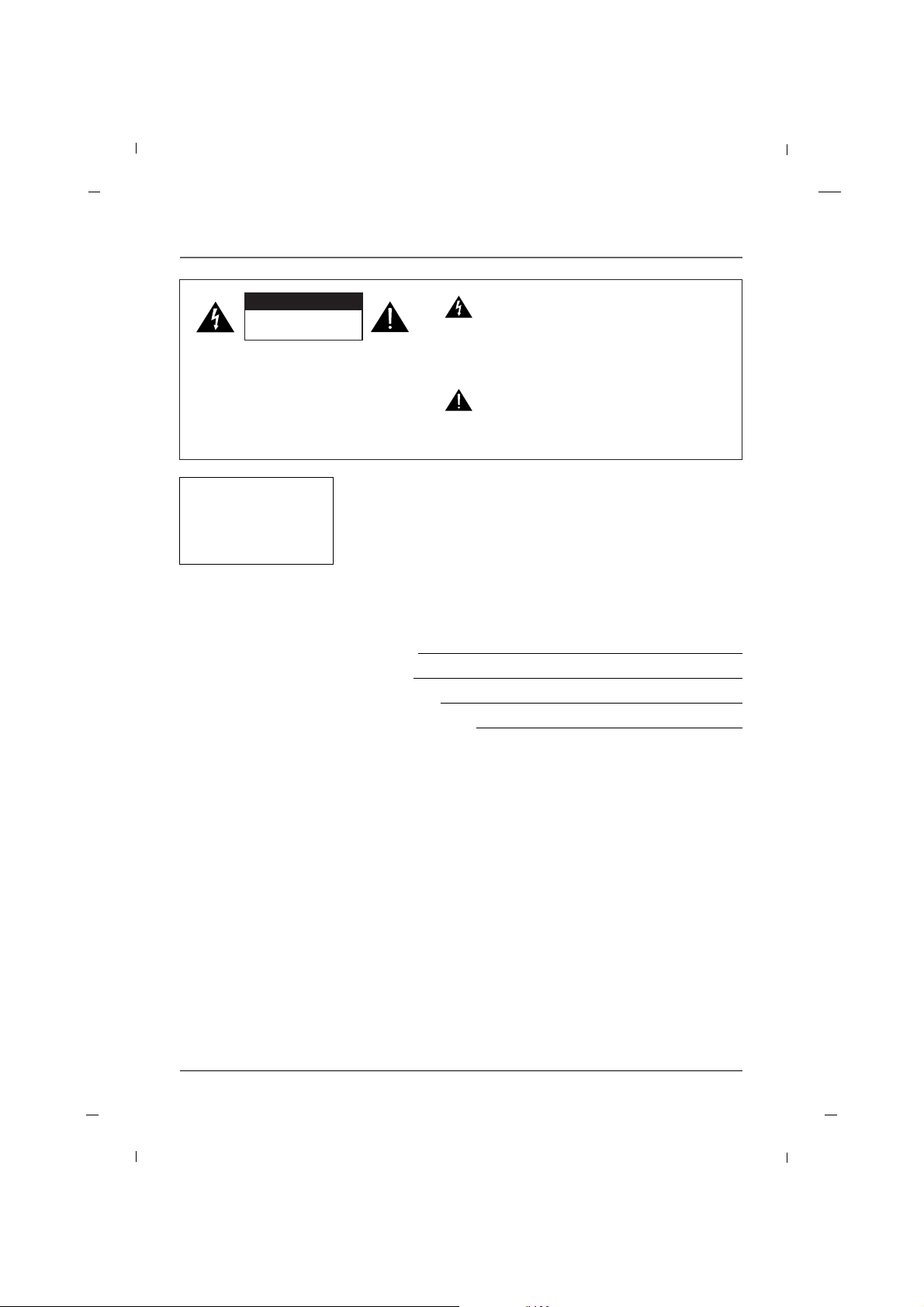
CAUTION:
TO REDUCE THE RISK OF ELECTRIC SHOCK
DO NOT REMOVE COVER (OR BACK).
NO USER SERVICEABLE PARTS INSIDE.
REFER TO QUALIFIED SERVICE PERSONNEL.
The lightning flash with arrowhead symbol, within an equilateral triangle, is intended to alert the
user to the presence of uninsulated “dangerous
voltage” within the product’s enclosure that may
be of sufficient magnitude to constitute a risk of
electric shock to persons.
The exclamation point within an equilateral triangle is intended to alert the user to the presence of important operating and maintenance
(servicing) instructions in the literature accompanying the appliance.
RISK OF ELECTRIC SHOCK
DO NOT OPEN
CC AA UU TT IIOO NN
TO PREVENT FIRE OR
SHOCK HAZARDS, DO NOT
EXPOSE THIS PRODUCT TO
RAIN OR MOISTURE.
WARNING
Please fill out the product registration card (packed separately) and return
it immediately. For US customers: Your RCA Consumer Electronics product
may also be registered at http://www.rcacommercialtv.com. Registering this
product allows us to contact you if needed.
Product Registration
This reminder is provided to call the CATV system installer’s attention to
Article 820-40 of the National Electric Code (U.S.A.). The code provides
guidelines for proper grounding and, in particular, specifies that the cable
ground shall be connected to the grounding system of the building, as
close to the point of the cable entry as practical.
NOTE TO CABLE TV INSTALLER
Keep your sales receipt to obtain warranty parts and service and for proof
of purchase. Attach it here and record the serial and model numbers in
case you need them. These numbers are located on the product.
Model No.
Serial No.
Purchase Date:
Dealer/Address/Phone:
Product Information
Page 3

Important Information
3
Do not attempt to modify this product in any way without written authorization from RCA.
Unauthorized modification could void the user’s authority to operate this product.
CAUTION
THESE SERVICING INSTRUCTIONS ARE FOR USE BY QUALIFIED SERVICE PERSONNEL ONLY. TO REDUCE
THE RISK OF ELECTRIC SHOCK, DO NOT PERFORM ANY SERVICING OTHER THAN THAT CONTAINED IN THE
OPERATING INSTRUCTIONS UNLESS YOU ARE QUALIFIED TO DO SO.
CAUTION
Apparatus shall not be exposed to dripping or splashing and no objects filled with liquids, such as vases, shall
not be placed on the apparatus.
WARNING
When used outside of U.S., other power supply cords may be used if the cord is approved by the local regulating agency.
CAUTION
Clean the exterior of this television by removing dust with a lint-free cloth.
CAUTION: To avoid damage to the surface of the television, do not use abrasive or chemical cleaning agents.
CLEANING AND DISINFECTION
This apparatus with class I construction shall be connected to a main socket outlet with a protective earthing
connection.
Page 4

Important Information
4
Main plug is the disconnecting device. The plug must remain readily operable.
DISCONNECTING DEVICE FROM MAINS
YOUR PRODUCT HAS BEEN MANUFACTURED AND TESTED WITH YOUR SAFETY IN MIND. HOWEVER,
IMPROPER USE CAN RESULT IN POTENTIAL ELECTRICAL SHOCK OR FIRE HAZARDS. TO AVOID DEFEATING
THE SAFEGUARDS THAT HAVE BEEN BUILT INTO YOUR NEW PRODUCT, PLEASE READ AND OBSERVE THE
FOLLOWING SAFETY POINTS WHEN INSTALLING AND USING YOUR NEW PRODUCT, AND SAVE THEM FOR
FUTURE REFERENCE. OBSERVING THE SIMPLE PRECAUTIONS DISCUSSED IN THIS MANUAL CAN HELP YOU
GET MANY YEARS OF ENJOYMENT AND SAFE OPERATION THAT ARE BUILT INTO YOUR NEW PRODUCT.
IMPORTANT SAFEGUARDS FOR YOU AND YOUR NEW PRODUCT
Note
-If the TV feels cold to the touch, there may be a small “flicker” when it is turned on. This is normal, there
is nothing wrong with the TV.
- Some minute dot defects may be visible on the screen, appearing as tiny red, green, or blue spots.
However, they have no adverse effect on the TVs performance.
-Avoid touching the LCD screen or holding your finger(s) against it for long periods of time. Doing so may
produce some temporary distortion effects on the screen.
This equipment has been tested and found to comply with the limits for a Class B digital device, pursuant to
Part 15 of the FCC Rules.
These limits are designed to provide reasonable protection against harmful interference when the equipment
is operated in a residential installation.
This equipment generates, uses and can radiate radio frequency energy and, if not installed and used in
accordance with the instruction manual, may cause harmful interference to radio communications.
However, there is no guarantee that interference will not occur in a particular installation.
If this equipment does cause harmful interference to radio or television reception, which can be determined
by turning the equipment off and on, the user is encouraged to try to correct the interference by one or
more of the following measures:
• Reorient or relocate the receiving antenna.
• Increase the separation between the equipment and receiver.
• Connect the equipment into an outlet on a circuit different from that to which the receiver is connected.
• Consult the dealer or an experienced radio/TV technician for help.
REGULATORY INFORMATION
Changes or modifications not expressly approved by the party responsible for compliance could void the
user’s authority to operate the equipment.
THE PARTY RESPONSIBLE FOR PRODUCT COMPLIANCE
(RCA Commercial Electronics)
(TELEPHONE NO : 1-800-RCA-2161)
CAUTION
Page 5
5
IMPORTANT SAFETY INSTRUCTIONS
Read before operating equipment
1. Read these instructions.
2. Keep these instructions.
3. Heed all warnings.
4. Follow all instructions.
5. Do not use this apparatus near water.
6. Clean only with dry cloth.
7. Do not block any ventilation openings.
Install in accordance with the manufacturer’s
instructions.
8. Do not install near any heat sources such as radiators, heat registers, stoves, or other apparatus
(including amplifiers) that produce heat.
9. Do not defeat the safety purpose of the polarized or grounding-type plug. A polarized plug
has two blades with one wider than the other.
A grounding type plug has two blades and a
third grounding prong. The wide blade or the
third prong is provided for your safety. If the
provided plug does not fit into your outlet, consult an electrician for replacement of the obsolete outlet.
10. Protect the power cord from being walked on or
pinched particularly at plugs, convenience receptacles, and the point where they exit from the
apparatus.
11. Only use attachments/accessories specified by the
manufacturer.
12. Use only with the cart, stand, tripod, bracket, or table specified by
the manufacturer, or sold with
the apparatus. When a cart is
used, use caution when moving
the cart/apparatus combination to
avoid injury from tip-over.
13. Unplug this apparatus during lightning storms or
when unused for long periods of time.
14. Refer all servicing to qualified service personnel.
Servicing is required when the apparatus has
been damaged in any way, such as powersupply
cord or plug is damaged, liquid has been spilled
or objects have fallen into the apparatus, the
apparatus has been exposed to rain or moisture,
does not operate normally, or has been dropped.
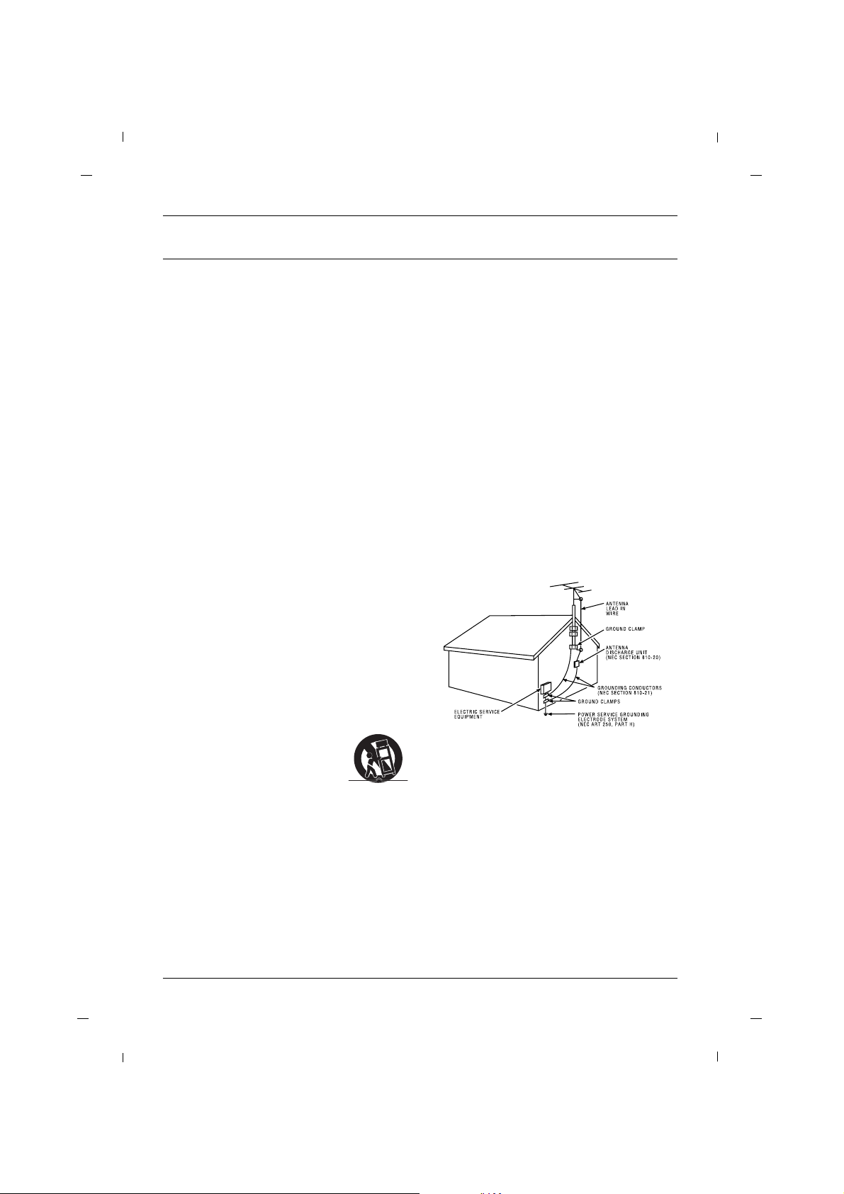
15. If an outside antenna or cable system is connected to the product, be sure the antenna or cable
system is grounded so as to provide some protection against voltage surges and built-up static
charges. Section 810 of the National Electrical
Code, ANSI/NFPA No. 70-1984 (Section 54 of
Canadian Electrical Code, Part 1) provides information with respect to proper grounding of the
mast and supporting structure, grounding of the
leadin wire to an antenna-discharge unit, size of
grounding conductors, location of antenna-discharge unit, connection to grounding electrodes,
and requirements for the grounding electrode.
See following example.
Note
- The lamp in this product contains mercury. Please dispose of in accordance with local, state, or federal
laws.
Page 6

Table of Contents
6
Important Information ..............................................2
IMPORTANT SAFETY INSTRUCTIONS ........................5
Chapter 1: Connections and Setup
Things to Consider Before You Connect ..................7
Protect Against Power Surges ........................7
Protect Devices from Overheating..................7
Position Cables Properly to Avoid Audio
Interference ......................................................7
Use Indirect Light ............................................7
Remote Control ................................................7
Check Supplied Parts........................................7
Controls And Connectors ..........................................8
Front Panel - J22H760 ......................................8
Rear Panel - J22H760 ......................................9
Front Panel - J26H700 ....................................10
Rear Panel - J26H700 ....................................11
Front Panel - J32H700 ....................................12
Rear Panel - J32H700 ....................................13
Front Panel - J42H750 ....................................14
Rear Panel - J42H750 ....................................15
Connections ..............................................................16
Vesa Standard TV Mounts ............................16
Antenna Connection......................................18
VCR Connection..............................................20
DVD Connection ............................................22
HDSTB Connection ........................................23
External A/V Source........................................26
Digital Audio Out ..........................................27
Pillow Speaker Wiring....................................28
PC Connection ................................................29
Resolution ......................................................31
USB in Setup ..................................................32
Headphone ....................................................32
Chapter 2: Using the Remote Control
Basic(User) Remote ........................................33
Master(Installer) Remote ..............................34
Put Batteries in the Remote ..........................34
Chapter 3: Using USB Clone Tool
USB Cloner Out-looking ................................35
Errors Table ....................................................35
Learning Connection ....................................36
Teaching Connection......................................37
Chapter 4: Basic Operation
Plug in the TV ................................................38
Turn on the TV................................................38
Channel Scan ..................................................38
Channel Selection ..........................................38
Volume Adjustment ......................................38
Sound Mute ....................................................38
Source Selection ............................................39
Language Selection........................................39
Chapter 5: Commercial Interface Menus
Commercial Interface Menus ..................................40
Chapter 6: Using the TV's Features
On Screen Menus ....................................................44
Setting up the TV Channel ....................................45
Auto Scan........................................................45
Add / Delete a Channel..................................46
Picture Controls ........................................................47
Adjusting The Picture Controls ....................47
Manual Picture Controls ................................48
Gamma............................................................49
Color Temperature ........................................50
Reset Picture Mode ........................................51
Advanced Video ......................................................52
Dynamic Noise Reduction ..............................52
CTI (Color Transient Intensity) ......................53
Flesh Tone ......................................................53
Adaptive Luma Control..................................54
Blue Mute ......................................................54
Back Light ......................................................55
Screen Mode ..................................................56
Sound Controls ........................................................57
Adjusting The Sound Controls ......................57
Manual Sound Controls ................................58
Sound Surround ............................................59
Equalizer ........................................................59
Digital Output ................................................60
Stereo/SAP Broadcast Setup ..........................61
Audio Language ............................................61
Time Setting ............................................................62
Time Zone Settings ........................................62
Auto Time Settings ........................................63
Manual Time Settings ....................................64
Auto On /Off Time Settings ..........................65
Sleep Timer ....................................................66
Captions ....................................................................67
Closed Caption - Analog................................67
Closed Caption - Digital ................................68
Digital Closed Caption Options ....................69
Reset ........................................................................70
Reset Default ..................................................70
Parental Control ......................................................71
Entering your password ................................71
Set Password ..................................................71
Ratings - Enable / Disable ..............................72
TV Ratings for USA ........................................73
Movie Ratings ................................................75
English TV Ratings for Canada ......................76
French TV Ratings for Canada ......................77
Downloadable Rating ....................................78
Block Unrated ................................................79
Clean All..........................................................79
Setting the PC Mode................................................80
Automatic Screen Adjustment ......................80
Manual Screen Adjustment ..........................81
USB Functions ..........................................................82
Picture Function ............................................82
Music Function ..............................................83
Specification ............................................................84
Chapter 7: Other Information
Troubleshooting ......................................................88
Limited Warranty ....................................................89
Care and Cleaning ....................................................90
CHILD SAFETY ..........................................................91
Page 7

Graphics contained within this publication are for representation only.
Chapter 1 7
Chapter 1: Connections and Setup
Things to Consider Before You Connect
• Connect all devices before you plug any of their power cords into the wall outlet or power strip. NEVER
plug your TV into an outlet that is controlled by a wall switch.
•Turn off the TV and/or device(s) before you connect or disconnect any cables.
• Make sure all antennas and cables are properly grounded. Refer to the Important Safety Instructions at
the beginning of the User's Guide.
Protect Against Power Surges
• Don’t block ventilation holes on any of the devices. Arrange the devices so that air can circulate freely.
• Don’t stack devices.
• If you place devices in a stand, make sure you allow adequate ventilation.
• If you connect an audio receiver or amplifier, place it on the top shelf so the heated air from it won’t flow
around other devices.
Protect Devices from Overheating
• Insert each cable firmly into the designated jack.
• If you place devices above the TV, route all cables down the side of the back of the TV instead of straight
down the middle.
• If your antenna uses 300-ohm twin lead cables, do not coil the cables. Also, keep the twin lead cables
away from audio/video cables.
Position Cables Properly to Avoid Audio Interference
Don’t place the TV where sunlight or room lighting will be directed toward the screen. Use soft or indirect
lighting.
Use Indirect Light
You will need a master remote or USB Cloner to set up the TV. Contact your RCA Commercial Distributor to
purchase these.
Remote Control
Check that the following parts were packed with your product.
Check Supplied Parts
Power Cord Owner’s Manual
1 2 3
4 5 6
7 8 9
0
SYSTEM
GUIDESLEEPSKIP
CCGO BACK
ANTENNAINPUT
SOUND
MENU OK INFO
CLEAR
MUTE
CH
VOL VOL
CH
ON-OFF
C O M M E R C I A L
R130K1
Remote (Optional)
Note
- If you need to replace your remote, call 1-800-RCA-2161. A shipping and handling fee, and the appropriate sales tax, will be charged upon ordering. Have your Visa, MasterCard, or Discover Card ready.
"User must use shielded signal interface cables with ferrite cores to maintain standard compliance for the product"
Page 8

Chapter 1: Connections and Setup
Chapter 18
Front Panel - J22H760
1. VOL- / VOL+
Adjusts sound level and menu settings.
2. CH / CH
Select a channel.
3. SOURCE
Selects the TV, AV1, AV 2, YPbPr, VGA, HDMI or USB mode.
4. MENU
Display on screen menus.
5. POWER
Switches the set on or off.
6. Power Indicator
Illuminates to bright blue when the TV is on. When the TV is powered off, this LED is also off.
Remote control sensor
Accepts the IR signal of remote controller.
6
1 2 3 4 5
VOL
SOURCE
MENU
CH
Note
- Image shown may differ from your TV.
Page 9

Chapter 1: Connections and Setup
Chapter 1 9
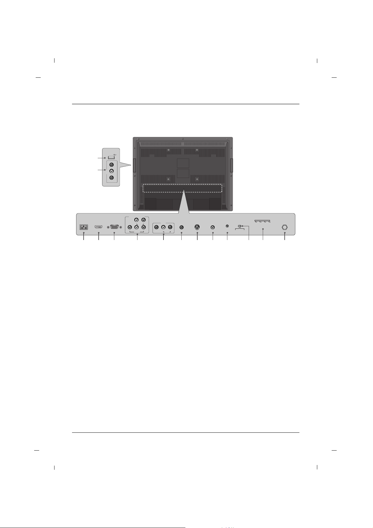
Rear Panel - J22H760
1. AC IN
This TV operates on AC power.
2. HDMI/DVI IN
Connect to the HDMI jack on devices with an
HDMI output.
This input can also be used as a DVI connection
with separate analog audio inputs.
3. RGB IN (PC)
Connect to the video output jack on your PC.
4. COMPONENT IN (YPbPr)
Video/Audio inputs for Component.
5. SERVICE
Used by clone device to learn settings in TV.
6. SPEAKER SWITCH
Used to select the speaker output type.
7. AV1
Connects to your Audio/Video devices using a
composite (Yellow/Red/White) cable.
8. SELECTION SWITCH
Selects the protocols and logic levels used on the
pillow-speaker port.
Warning
This switch controls the voltage levels used to
power an external pillow speaker. It allows the
television to interface to different pillow speaker
types(RCA, LG/Zenith, Philips). Setting this switch
incorrectly could damage your pillow speaker
device.
9. AUDIO IN (RGB/DVI)
Connect to the audio output jack on your PC.
10.PILLOW JACK IN
Used to connect to pillow speaker.
11.ANTENNA/CABLE IN
Connect to your antenna or cable box for TV signal.
12.DIGITAL AUDIO OUT(COAXIAL)
Connect digital audio to various types of equipment.
13.USB IN
USB device interface.
14.AV2
Connects to your Audio/Video devices using a
composite (Yellow/Red/White) cable.
15.Headphone
Connect the headphone plug to this socket.
13
15
14
VIDEO
L-AUDIO-R
AV2
H/P
USB IN
HDMI/DVIINRGB IN
(PC)
AUDIO IN
(RGB/DVI)
DIGITAL AUDIO
OUT(COAXIAL)
ANTENNA/
CABLE IN
3 9 1110 122
VIDEO
YPbPr
LR
COMPONENT IN
AUDIO
4 7 851
AC IN
SERVICE
PILLOW JACK IN
SPEAKER
SWITCH
PILLOW
SPEAKER
NORMAL
SPEAKER
AV1
AUDIO
L
VIDEO
R
6
ZEN PLS OFF RCA
Note
- Image shown may differ from your TV.
Page 10

Chapter 1: Connections and Setup
Chapter 110
Front Panel - J26H700
SOURCE
MENU
VOL
CH
6
1 2 3 4 5
SOURCE
MENU
VOL
CH
Note
- Image shown may differ from your TV.
1. VOL- / VOL+
Adjusts sound level and menu settings.
2. CH / CH
Select a channel.
3. SOURCE
Selects the TV, AV1, AV 2, YPbPr, VGA, HDMI or USB mode.
4. MENU
Display on screen menus.
5. POWER
Switches the set on or off.
6. Power Indicator
Illuminates to bright blue when the TV is on. When the TV is powered off, this LED is also off.
Remote control sensor
Accepts the IR signal of remote controller.
Page 11
Chapter 1: Connections and Setup
Chapter 1 11
Rear Panel - J26H700
1. AC IN
This TV operates on AC power.
2. HDMI/DVI IN
Connect to the HDMI jack on devices with an
HDMI output.
This input can also be used as a DVI connection
with separate analog audio inputs.
3. RGB IN (PC)
Connect to the video output jack on your PC.
4. COMPONENT IN (YPbPr)
Video/Audio inputs for Component.
5. AV1
Connects to your Audio/Video devices using a
composite (Yellow/Red/White) cable.
6. AUDIO IN (RGB/DVI)
Connect to the audio output jack on your PC.
7. ANTENNA/CABLE IN
Connect to your antenna or cable box for TV signal.
8. DIGITAL AUDIO OUT(COAXIAL)
Connect digital audio to various types of equipment.
9. SERVICE
Used by clone device to learn settings in TV.
10.SPEAKER SWITCH
Used to select the speaker output type.
11.SELECTION SWITCH
Selects the protocols and logic levels used on the
pillow-speaker port.
Warning
This switch controls the voltage levels used to
power an external pillow speaker. It allows the
television to interface to different pillow speaker
types(RCA, LG/Zenith, Philips). Setting this switch
incorrectly could damage your pillow speaker
device.
12.PILLOW JACK IN
Used to connect to pillow speaker.
13.USB IN
USB device interface.
14.AV2
Connects to your Audio/Video devices using a
composite (Yellow/Red/White) cable.
R - AUDIO - L
AV2
VIDEO
USB IN
13
14
HDMI/DVIINRGB IN
(PC)
AUDIO IN
(RGB/DVI)
DIGITAL AUDIO
OUT(COAXIAL)
ANTENNA/
CABLE IN
3 6 7 8 12111092
VIDEO
YPbPr
LR
COMPONENT IN
AUDIO
AV1
AUDIO
L
VIDEO
R
4 51
AC IN
SERVICE
SPEAKER
SWITCH
PILLOW
SPEAKER
NORMAL
SPEAKER
PILLOW JACK IN
ZEN PLS OFF RCA
Note
- Image shown may differ from your TV.
Page 12

Chapter 1: Connections and Setup
Chapter 112
Front Panel - J32H700
SOURCE
MENU
VOL
CH
6
1 2 3 4 5
SOURCE
MENU
VOL
CH
Note
- Image shown may differ from your TV.
1. VOL- / VOL+
Adjusts sound level and menu settings.
2. CH / CH
Select a channel.
3. SOURCE
Selects the TV, AV1, AV 2, YPbPr, VGA, HDMI or USB mode.
4. MENU
Display on screen menus.
5. POWER
Switches the set on or off.
6. Power Indicator
Illuminates to bright blue when the TV is on. When the TV is powered off, this LED is also off.
Remote control sensor
Accepts the IR signal of remote controller.
Page 13

Chapter 1: Connections and Setup
Chapter 1 13
Rear Panel - J32H700
1. AC IN
This TV operates on AC power.
2. HDMI/DVI IN
Connect to the HDMI jack on devices with an
HDMI output.
This input can also be used as a DVI connection
with separate analog audio inputs.
3. RGB IN (PC)
Connect to the video output jack on your PC.
4. COMPONENT IN (YPbPr)
Video/Audio inputs for Component.
5. AV1
Connects to your Audio/Video devices using a
composite (Yellow/Red/White) cable.
6. AUDIO IN (RGB/DVI)
Connect to the audio output jack on your PC.
7. ANTENNA/CABLE IN
Connect to your antenna or cable box for TV signal.
8. DIGITAL AUDIO OUT(COAXIAL)
Connect digital audio to various types of equipment.
9. SERVICE
Used by clone device to learn settings in TV.
10.SPEAKER SWITCH
Used to select the speaker output type.
11.SELECTION SWITCH
Selects the protocols and logic levels used on the
pillow-speaker port.
Warning
This switch controls the voltage levels used to
power an external pillow speaker. It allows the
television to interface to different pillow speaker
types(RCA, LG/Zenith, Philips). Setting this switch
incorrectly could damage your pillow speaker
device.
12.PILLOW JACK IN
Used to connect to pillow speaker.
13.USB IN
USB device interface.
14.AV2
Connects to your Audio/Video devices using a
composite (Yellow/Red/White) cable.
R - AUDIO - L
AV2
VIDEO
USB IN
13
14
HDMI/DVIINRGB IN
(PC)
AUDIO IN
(RGB/DVI)
DIGITAL AUDIO
OUT(COAXIAL)
ANTENNA/
CABLE IN
3 6 7 8 12111092
VIDEO
YPbPr
LR
COMPONENT IN
AUDIO
AV1
AUDIO
L
VIDEO
R
4 51
AC IN
SERVICE
SPEAKER
SWITCH
PILLOW
SPEAKER
NORMAL
SPEAKER
PILLOW JACK IN
ZEN PLS OFF RCA
Note
- Image shown may differ from your TV.
Page 14

Chapter 1: Connections and Setup
Chapter 114
Front Panel - J42H750
VOL SOURCE MENUCH
12345
VOL SOURCE MENUCH
6
Note
- Image shown may differ from your TV.
1. VOL- / VOL+
Adjusts sound level and menu settings.
2. CH / CH
Select a channel.
3. SOURCE
Selects the TV, AV1, AV 2, YPbPr, VGA, HDMI or USB mode.
4. MENU
Display on screen menus.
5. POWER
Switches the set on or off.
6. Power Indicator
Illuminates to bright blue when the TV is on. When the TV is powered off, this LED is also off.
Remote control sensor
Accepts the IR signal of remote controller.
Page 15
Chapter 1: Connections and Setup
Chapter 1 15
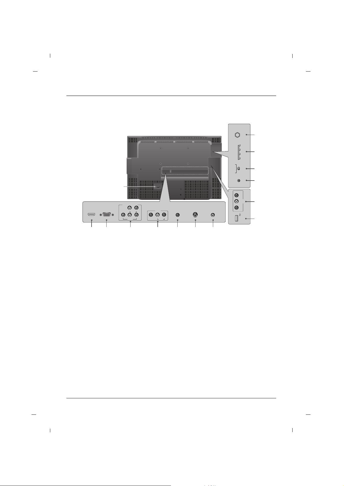
Rear Panel - J42H750
14
HDMI/DVIINRGB IN
(PC)
AUDIO IN
(RGB/DVI)
DIGITAL AUDIO
OUT(COAXIAL)
ANTENNA/
CABLE IN
2 5 6 71
VIDEO
YPbPr
LR
COMPONENT IN
AUDIO
AV1
AUDIO
L
VIDEO
R
3 4
SERVICE
SPEAKER
SWITCH
PILLOW
SPEAKER
NORMAL
SPEAKER
PILLOW JACK IN
10
11
9
8
ZEN PLS OFF RCA
12
13
AV2
VIDEO L - AUDIO - R
USB IN
Note
- Image shown may differ from your TV.
1. HDMI/DVI IN
Connect to the HDMI jack on devices with an
HDMI output.
This input can also be used as a DVI connection
with separate analog audio inputs.
2. RGB IN (PC)
Connect to the video output jack on your PC.
3. COMPONENT IN (YPbPr)
Video/Audio inputs for Component.
4. AV1
Connects to your Audio/Video devices using a
composite (Yellow/Red/White) cable.
5. AUDIO IN (RGB/DVI)
Connect to the audio output jack on your PC.
6. ANTENNA/CABLE IN
Connect to your antenna or cable box for TV signal.
7. DIGITAL AUDIO OUT(COAXIAL)
Connect digital audio to various types of equipment.
8. PILLOW JACK IN
Used to connect to pillow speaker.
9. SELECTION SWITCH
Selects the protocols and logic levels used on the
pillow-speaker port.
Warning
This switch controls the voltage levels used to
power an external pillow speaker. It allows the
television to interface to different pillow speaker
types(RCA, LG/Zenith, Philips). Setting this switch
incorrectly could damage your pillow speaker
device.
10.SPEAKER SWITCH
Used to select the speaker output type.
11.SERVICE
Used by clone device to learn settings in TV.
12.USB IN
USB device interface.
13.AV2
Connects to your Audio/Video devices using a
composite (Yellow/Red/White) cable.
14.AC IN
This TV operates on AC power.
Page 16

Chapter 1: Connections and Setup
Chapter 116
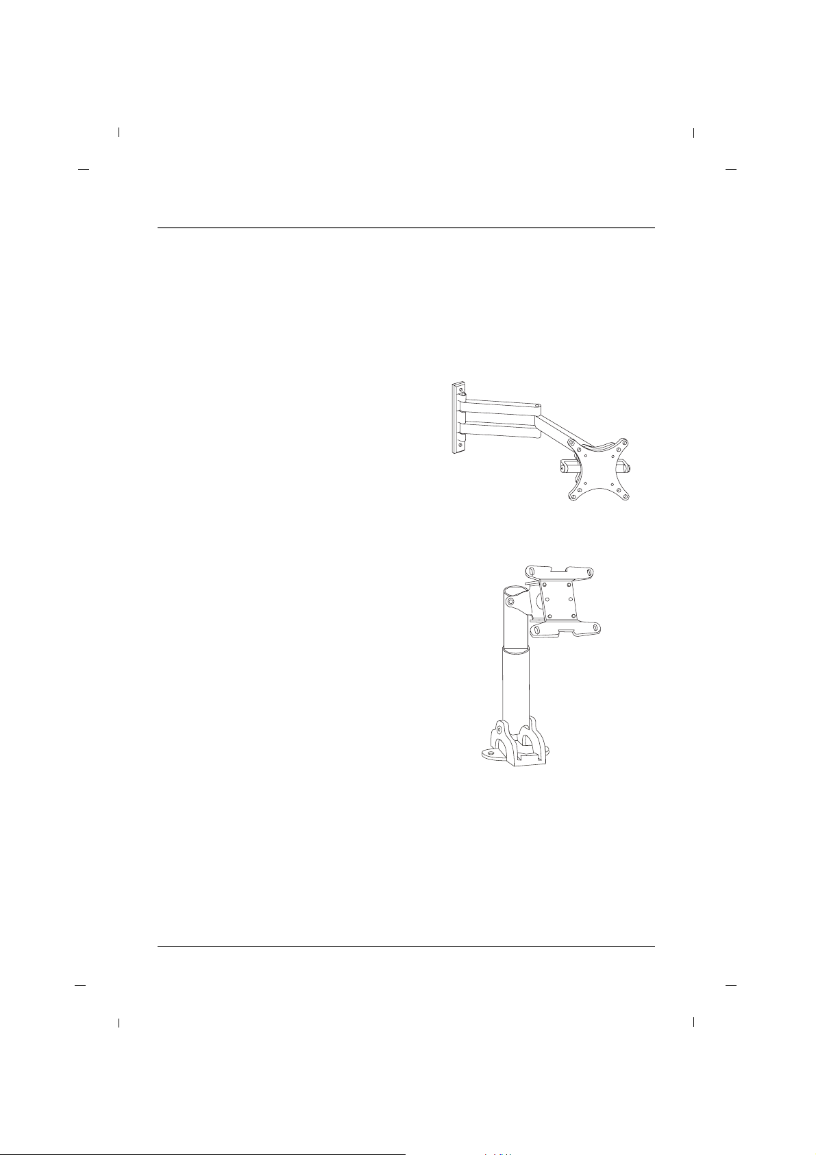
Vesa Standard TV Mounts - 26/32/42 inches
General Guidelines: Choosing a location for
installing a VESA Standard Mount
Typical Wall Stud Type Mount with Swivel Bracket
Be sure the style of stand selected is capable of
supporting the weight of the TV.
If the mount will be on a wall, a typical wooden
stud behind the wall board would be the preferred choice for a location to attach the wall
mount. The wall mount location chosen should be
appropriate for drilling holes and have available
the required power source as well as
antenna/cable and other equipment leads.
For pedestal-type mounts, a sturdy surface on a
desk or other similar flat table-like surface would
be the appropriate location for mounting a
pedestal-style TV stand. (Some stands are portable
and can be moved from one location to another.)
Be sure all safety considerations are followed.
Most stands are designed so that the wiring would
be threaded through the stand itself or a loopthrough style clamp so that the wiring is neatly
bunched and not strung in such a way as to create
a potential hazard to the user.
The following examples are VESA Standard 200mm wall mounts. Since there are numerous types of stands
and mounts available, only a few are shown here. Refer to the instructions provided with the TV stand that
will be used to mount the TV.
Note
- Image shown may differ from your TV.
- Screw length needed depends on the wall mount used. For further information, refer to the VESA Wall
Mounting Instruction Guide.
Caution: Tightening wall mount screws that are too long could cause damage to the internal components of
this television.
Use M5 X “L” bolts to mount LCD. (“L” = Wall Mount bracket thickness + 0.5 inch or below for
J26H700/J32H700/J42H750)
You must use a UL listed wall mount or the DTI Services, LLC DTI-006 Wall Mount Bracket whenever Wall
Mounting this television.
A skilled person should be contacted to perform the installation of the television and wall mount.
Specification of a generic "UL Listed wall mount" should additionally include : minimum weight that the
mount must be able to support, minimum screen size that the mount must be able to support, instructions
furnished as part of the wall mount must be closely followed, the wall mount must be suitable to support
the type of television under consideration.
Page 17
Chapter 1: Connections and Setup
Chapter 1 17
Vesa Standard TV Mounts - 22 inch
To the right are some examples of VESA standard
mounts. Since there are numerous types of stands
and mounts available, only a few are shown here.
Refer to the instructions provided with the TV
stand that will be used to mount the TV. Be sure
the style of stand selected is capable of supporting
the weight of the TV and is appropriate for the
application.
General Guidelines: Choosing a Location for
installing a VESA Standard Mount
If the mount will be on a wall, a typical wooden
stud behind the wall board would be the preferred choice for a location to attach the wall
mount. The wall mount location chosen should be
appropriate for drilling holes and have available
the required power source as well as
antenna/cable and any other equipment leads as
necessary.
Wall Mounts
A sturdy surface on a desk or other similar flat
table-like furniture would be the appropriate location for mounting a pedestal-style TV stand.
Most stands are designed so that the wiring is
threaded through the stand itself or a
loopthrough style clamp so that the wiring is neatly bunched and not strung in such a way as to create a potential hazard to the user.
(Some stands are portable and can be moved from
one location to another.) Be sure all safety considerations are followed.
Pedestal Mounts and Stands
Typical Wall Stud Type Mount
with Swivel Bracket
Typical Pedestal Type Mount with
Swivel Bracket
Caution: Tightening wall mount screws that are too long could cause damage to the internal components of
this television.
Use M4 X “L” bolts to mount LCD. (“L” = Wall Mount bracket thickness + 0.3 inch or below for
J22H760)
You must use a UL listed wall mount or the DTI Services, LLC DTI-006 Wall Mount Bracket whenever Wall
Mounting this television.
A skilled person should be contacted to perform the installation of the television and wall mount.
Specification of a generic "UL Listed wall mount" should additionally include : minimum weight that the
mount must be able to support, minimum screen size that the mount must be able to support, instructions
furnished as part of the wall mount must be closely followed, the wall mount must be suitable to support
the type of television under consideration.
Page 18
Chapter 1: Connections and Setup
Chapter 118
AUDIO IN
(RGB/DVI)
DIGITAL AUDIO
OUT(COAXIAL)
ANTENNA/
CABLE IN
AV1
AUDIO
L
VIDEO
R
Rear panel of the set
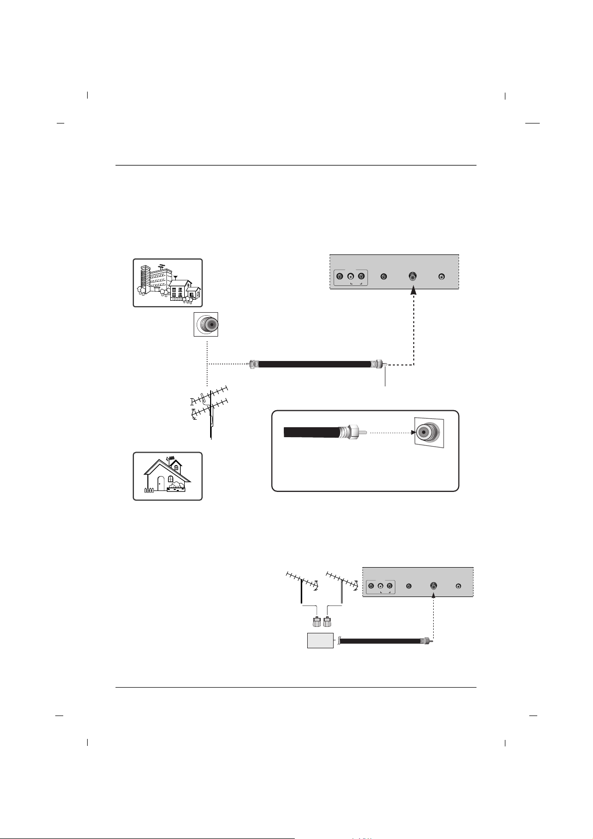
Antenna Connection - 26/32/42 inches
Note
-To improve the picture quality in a poor signal
area, please purchase a signal amplifier and
install properly.
- If the antenna is not installed properly, contact
your dealer for assistance.
AUDIO IN
(RGB/DVI)
DIGITAL AUDIO
OUT(COAXIAL)
ANTENNA/
CABLE IN
AV1
AUDIO
L
VIDEO
R
Rear panel of the set
Multi-family Dwellings/ Apartments
(Connect to wall antenna socket)
Single-family Dwellings /Houses
(Connect to wall jack for outdoor antenna)
Wall Antenna Socket
Outdoor Antenna
RF Coaxial Wire (75 ohm)
Turn clockwise to tighten.
Be careful not to bend the bronze wire when
connecting to an antenna port.
* Separately purchase a RF Coaxial Wire(75 ohm)
Signal
Amplifier
VHF UHF
VHF
UHF
Page 19

Chapter 1: Connections and Setup
19Chapter 1
AUDIO IN
(RGB/DVI)
DIGITAL AUDIO
OUT(COAXIAL)
ANTENNA/
CABLE IN
PILLOW JACK IN
AUDIO
R
ZEN PLS OFF RCA
AUDIO IN
(RGB/DVI)
DIGITAL AUDIO
OUT(COAXIAL)
ANTENNA/
CABLE IN
PILLOW JACK IN
AUDIO
R
ZEN PLS OFF RCA
Rear panel of the set
Antenna Connection - 22 inch
Note
-To improve the picture quality in a poor signal
area, please purchase a signal amplifier and
install properly.
- If the antenna is not installed properly, contact
your dealer for assistance.
Rear panel of the set
Multi-family Dwellings/ Apartments
(Connect to wall antenna socket)
Single-family Dwellings /Houses
(Connect to wall jack for outdoor antenna)
Wall Antenna Socket
Outdoor Antenna
RF Coaxial Wire (75 ohm)
Turn clockwise to tighten.
Be careful not to bend the bronze wire when
connecting to an antenna port.
* Separately purchase a RF Coaxial Wire(75 ohm)
Signal
Amplifier
VHF UHF
VHF
UHF
Page 20
Chapter 1: Connections and Setup
20
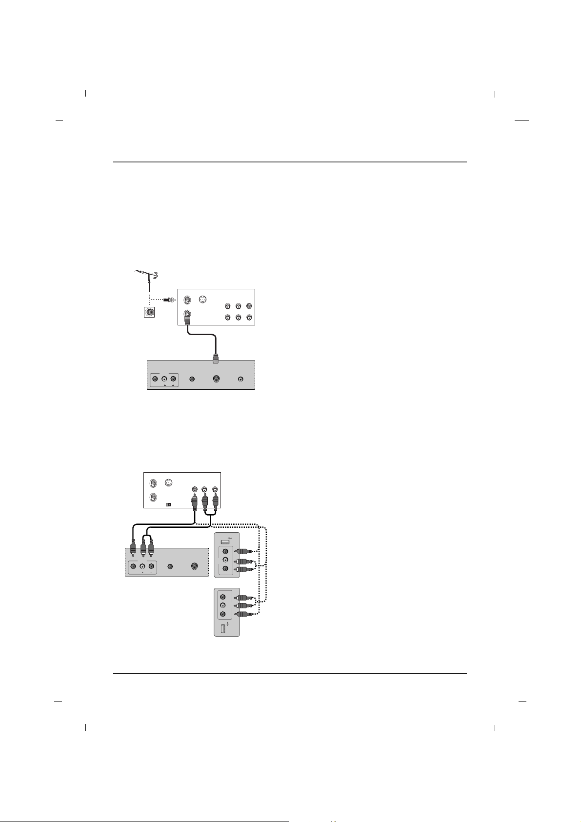
VCR Connection - 26/32/42 inches
AA When connecting with an antenna
AUDIO IN
(RGB/DVI)
DIGITAL AUDIO
OUT(COAXIAL)
ANTENNA/
CABLE IN
AV1
AUDIO
L
VIDEO
R
ANT IN
ANT OUT S-VIDEO
IN
OUT
(R) AUDIO (L) VIDEO
1. Connect the Antenna out socket of the VCR to
the Antenna input socket on the TV.
2. Power up the VCR and Television.
3. Tune the TV to the channel output by the VCR.
(typically ch.3 or 4.)
4. Refer to the VCR manual for operating instructions.
VCR
Rear panel of the set
AA When connecting with an RCA cable
R - AUDIO - L
AV2
VIDEO
USB IN
AUDIO IN
(RGB/DVI)
ANTENNA/
CABLE IN
AV1
AUDIO
L
VIDEO
R
ANT IN
ANT OUT S-VIDEO
IN
OUT
(L) AUDIO (R)VIDEO
OUTPUT
SWITCH
AV2
VIDEO L - AUDIO - R
USB IN
1. Connect the AUDIO/VIDEO jacks between TV and
VCR. Match the jack colors (Video = yellow, Audio
Left = white, and Audio Right = red)
2. Insert a video tape into the VCR and press PLAY
on the VCR.
3. Select the AV1 or AV2 input source using the
INPUT button on the remote control.
4. Refer to the VCR manual for operating instructions.
VCR
Rear panel of the set
Side panel of
the set
26/32 inches
42 inch
- To avoid picture noise (interference), leave an adequate distance between the TV and the VCR.
Chapter 1
Page 21
Chapter 1: Connections and Setup
21Chapter 1
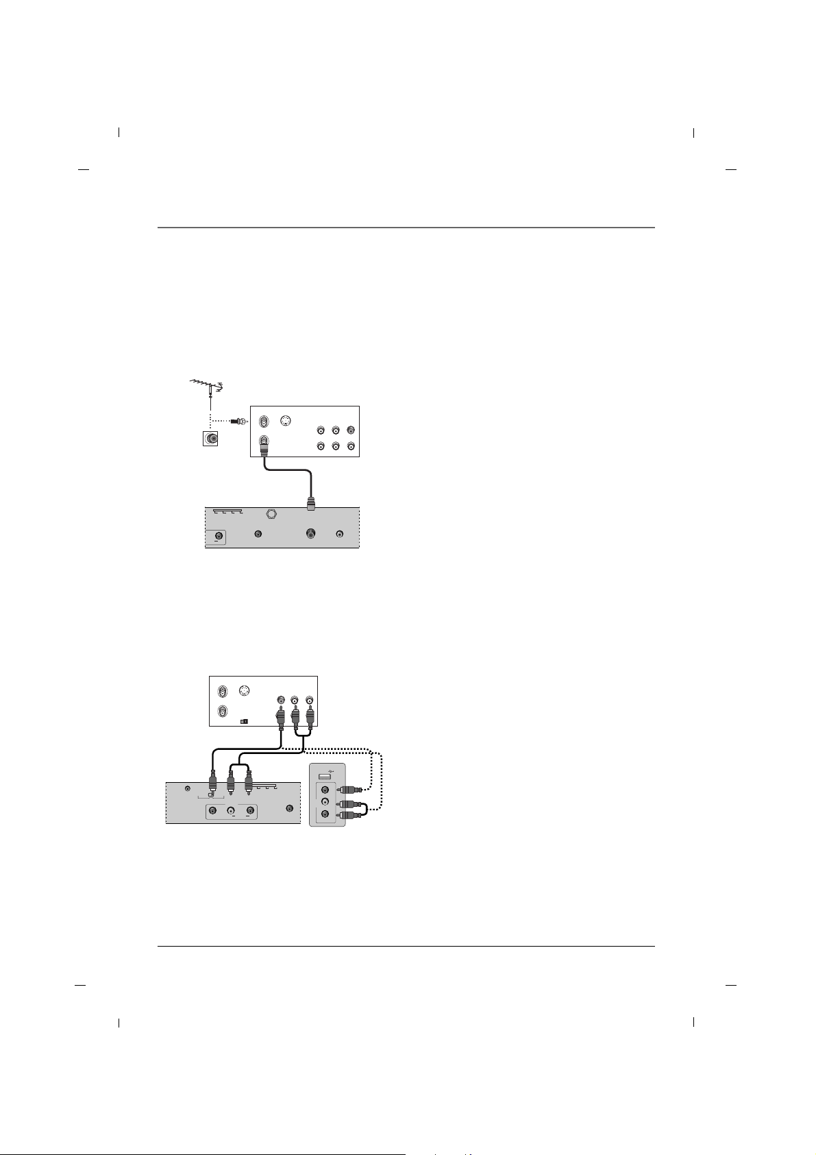
VCR Connection - 22 inch
AA When connecting with an antenna
AUDIO IN
(RGB/DVI)
DIGITAL AUDIO
OUT(COAXIAL)
ANTENNA/
CABLE IN
PILLOW JACK IN
AUDIO
R
ZEN PLS OFF RCA
ANT IN
ANT OUT S-VIDEO
IN
OUT
(R) AUDIO (L) VIDEO
1. Connect the Antenna out socket of the VCR to
the Antenna input socket on the TV.
2. Power up the VCR and Television.
3. Tune the TV to the channel output by the VCR.
(typically ch.3 or 4.)
4. Refer to the VCR manual for operating instruc-
tions.
VCR
Rear panel of the set
AA When connecting with an RCA cable
AUDIO IN
(RGB/DVI)
SERVICE
SPEAKER
SWITCH
PILLOW
SPEAKER
NORMAL
SPEAKER
AV1
AUDIO
L
VIDEO
R
ZEN PLS OFF RCA
VIDEO
L - AUDIO - R
AV2
USB IN
ANT IN
ANT OUT S-VIDEO
IN
OUT
(L) AUDIO (R)VIDEO
OUTPUT
SWITCH
1. Connect the AUDIO/VIDEO jacks between TV and
VCR. Match the jack colors (Video = yellow, Audio
Left = white, and Audio Right = red)
2. Insert a video tape into the VCR and press PLAY
on the VCR.
3. Select the AV1 or AV2 input source using the
INPUT button on the remote control.
4. Refer to the VCR manual for operating instruc-
tions.
VCR
Rear panel of the set Side panel of the set
- To avoid picture noise (interference), leave an adequate distance between the TV and the VCR.
Page 22
Chapter 1: Connections and Setup
22
AA When connecting with a Component cable
HDMI/DVIINRGB IN
(PC)
VIDEO
YPb Pr
LR
COMPONENT IN
AUDIO
(L) AUDIO (R)
Y
Pb Pr
1. Connect the video outputs (Y, PB, PR) of the DVD
to the COMPONENT VIDEO(Y, Pb, Pr) jacks on
the set.
2. Connect the audio outputs of the DVD to the
COMPONENT AUDIO L, R jacks on the set.
3. Turn on the DVD player, insert a DVD.
4. Select YPbPr source using the INPUT button on
the remote control.
5. Refer to the DVD player's manual for operating
instructions.
DVD
Rear panel of the set
DVD Connection
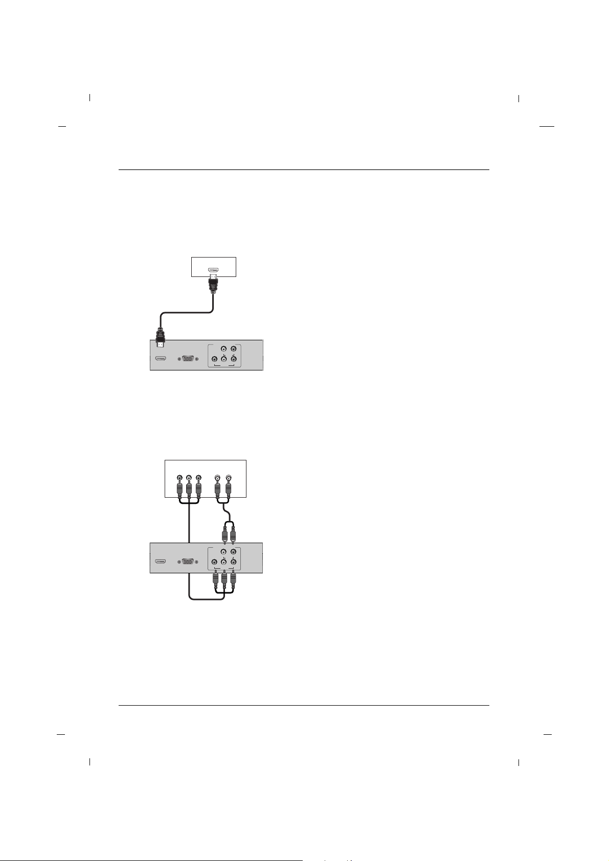
AA When connecting with a HDMI cable
HDMI/DVIINRGB IN
(PC)
VIDEO
YPb Pr
LR
COMPONENT IN
AUDIO
HDMI-DVD OUTPUT
1. Connect the HDMI output of the DVD to the
HDMI/DVI IN jack on the set.
2. Select HDMI input source using the INPUT button
on the remote control.
3. Refer to the DVD player's manual for operating
instructions.
DVD
Rear panel of the set
Chapter 1
Page 23
Chapter 1: Connections and Setup
23Chapter 1
- This TV can receive Digital Over-the-air/Cable signals without an external digital set-top box.
However, if you do receive Digital signals from a digital set-top box or other digital external device, refer
to the figure as shown below.
HDSTB Connection
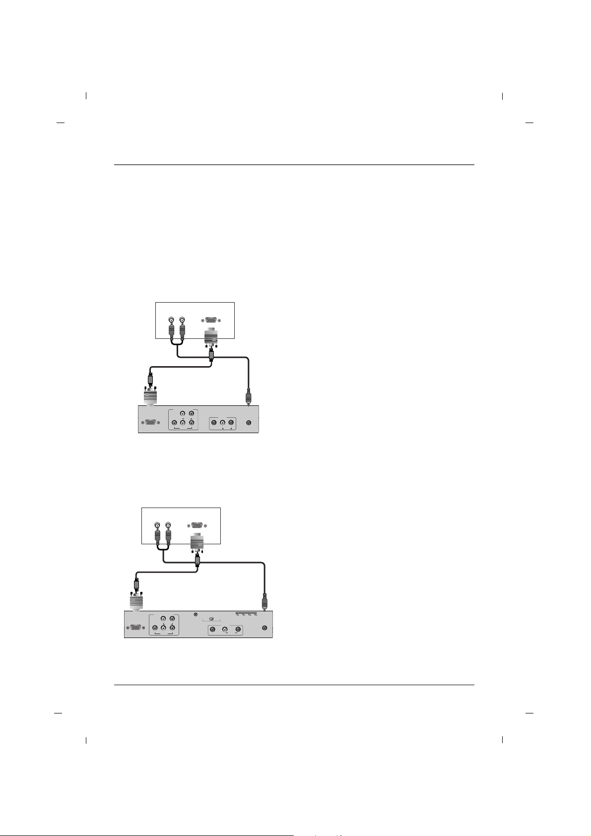
AA When connecting with a D-Sub 15 pin cable - 26/32/42 inches
RGB IN
(PC)
AUDIO IN
(RGB/DVI)
VIDEO
YPbPr
LR
COMPONENT IN
AUDIO
AV1
AUDIO
L
VIDEO
R
(R) AUDIO (L) RGB-DTV OUTPUT
1. Connect the RGB output of the digital set-top
box to the RGB IN (PC) jack on the set.
2. Connect the audio outputs of the set-top box to
the AUDIO IN (RGB/DVI) jack on the set.
3. Turn on the digital set-top box.
4. Select VGA input source using the INPUT button
on the remote control.
5. Refer to the digital set-top box manual for operating instructions.
Digital Set-top Box
Rear panel of the set
AA When connecting with a D-Sub 15 pin cable - 22 inch
RGB IN
(PC)
AUDIO IN
(RGB/DVI)
VIDEO
YPbPr
LR
COMPONENT IN
AUDIO
SERVICE
SPEAKER
SWITCH
PILLOW
SPEAKER
NORMAL
SPEAKER
AV1
AUDIO
L
VIDEO
R
ZEN PLS OFF RCA
(R) AUDIO (L) RGB-DTV OUTPUT
1. Connect the RGB output of the digital set-top
box to the RGB IN (PC) jack on the set.
2. Connect the audio outputs of the set-top box to
the AUDIO IN (RGB/DVI) jack on the set.
3. Turn on the digital set-top box.
4. Select VGA input source using the INPUT button
on the remote control.
5. Refer to the digital set-top box manual for operating instructions.
Digital Set-top Box
Rear panel of the set
Page 24
Chapter 1: Connections and Setup
24
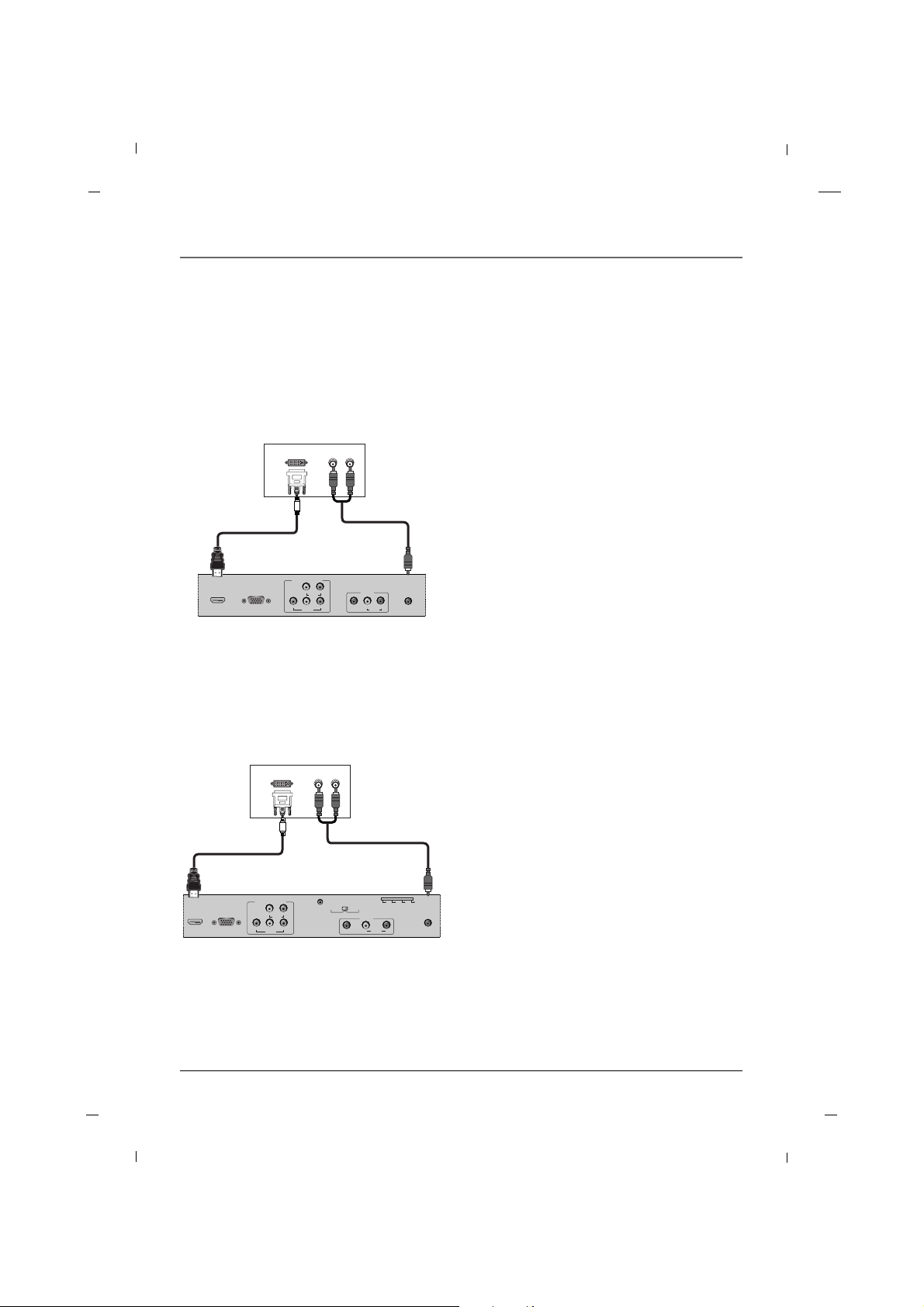
AA When connecting with a HDMI to DVI cable - 26/32/42 inches
HDMI/DVIINRGB IN
(PC)
AUDIO IN
(RGB/DVI)
VIDEO
YPbPr
LR
COMPONENT IN
AUDIO
AV1
AUDIO
L
VIDEO
R
DVI-DTV OUTPUT
(R) AUDIO (L)
1. Connect the DVI output of the digital set-top box
to the HDMI/DVI IN jack on the set.
2. Connect the audio outputs of the set-top box to
the AUDIO IN (RGB/DVI) jack on the set.
3. Turn on the digital set-top box.
4. Select HDMI input source using the INPUT button
on the remote control.
5. Refer to the digital set-top box manual for oper-
ating instructions.
Digital Set-top Box
Rear panel of the set
AA When connecting with a HDMI to DVI cable - 22 inch
HDMI/DVIINRGB IN
(PC)
AUDIO IN
(RGB/DVI)
VIDEO
YPbPr
LR
COMPONENT IN
AUDIO
SERVICE
SPEAKER
SWITCH
PILLOW
SPEAKER
NORMAL
SPEAKER
AV1
AUDIO
L
VIDEO
R
ZEN PLS OFF RCA
DVI-DTV OUTPUT
(R) AUDIO (L)
1. Connect the DVI output of the digital set-top box
to the HDMI/DVI IN jack on the set.
2. Connect the audio outputs of the set-top box to
the AUDIO IN (RGB/DVI) jack on the set.
3. Turn on the digital set-top box.
4. Select HDMI input source using the INPUT button
on the remote control.
5. Refer to the digital set-top box manual for oper-
ating instructions.
Digital Set-top Box
Rear panel of the set
Chapter 1
Page 25
Chapter 1: Connections and Setup
25Chapter 1
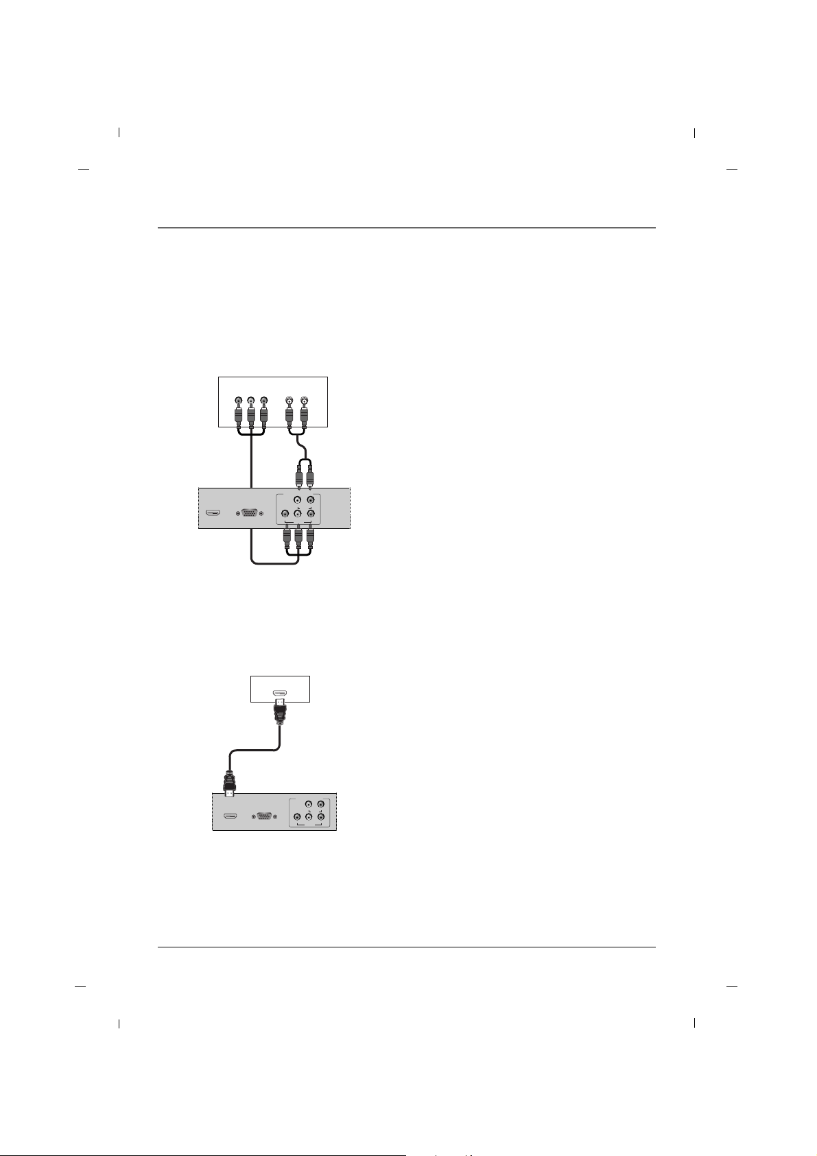
AA When connecting with a Component cable
HDMI/DVIINRGB IN
(PC)
VIDEO
YPb Pr
LR
COMPONENT IN
AUDIO
(L) AUDIO (R)
Y
Pb Pr
1. Connect the video outputs (Y, PB, PR) of the digital set-top box to the COMPONENT VIDEO(Y,
Pb, Pr) jacks on the set.
2. Connect the audio outputs of the digital set-top
box to the COMPONENT AUDIO L, R jacks on the
set.
3. Turn on the digital set-top box.
4. Select YPbPr source using the INPUT button on
the remote control.
5. Refer to the digital set-top box manual for operating instructions.
Digital Set-top Box
Rear panel of the set
AA When connecting with a HDMI cable
HDMI/DVIINRGB IN
(PC)
VIDEO
YPbPr
LR
COMPONENT IN
AUDIO
HDMI-DTV OUTPUT
1. Connect the HDMI output of the digital set-top
box to the HDMI/DVI IN jack on the set.
2. Turn on the digital set-top box.
3. Select HDMI input source using the INPUT button
on the remote control.
4. Refer to the digital set-top box manual for operating instructions.
Digital Set-top Box
Rear panel of the set
Page 26
Chapter 1: Connections and Setup
26
R - AUDIO - L
AV2
VIDEO
USB IN
AUDIO IN
(RGB/DVI)
ANTENNA/
CABLE IN
AV1
AUDIO
L
VIDEO
R
L-AUDIO-RVIDEO
OUT
AV2
VIDEO L - AUDIO - R
USB IN
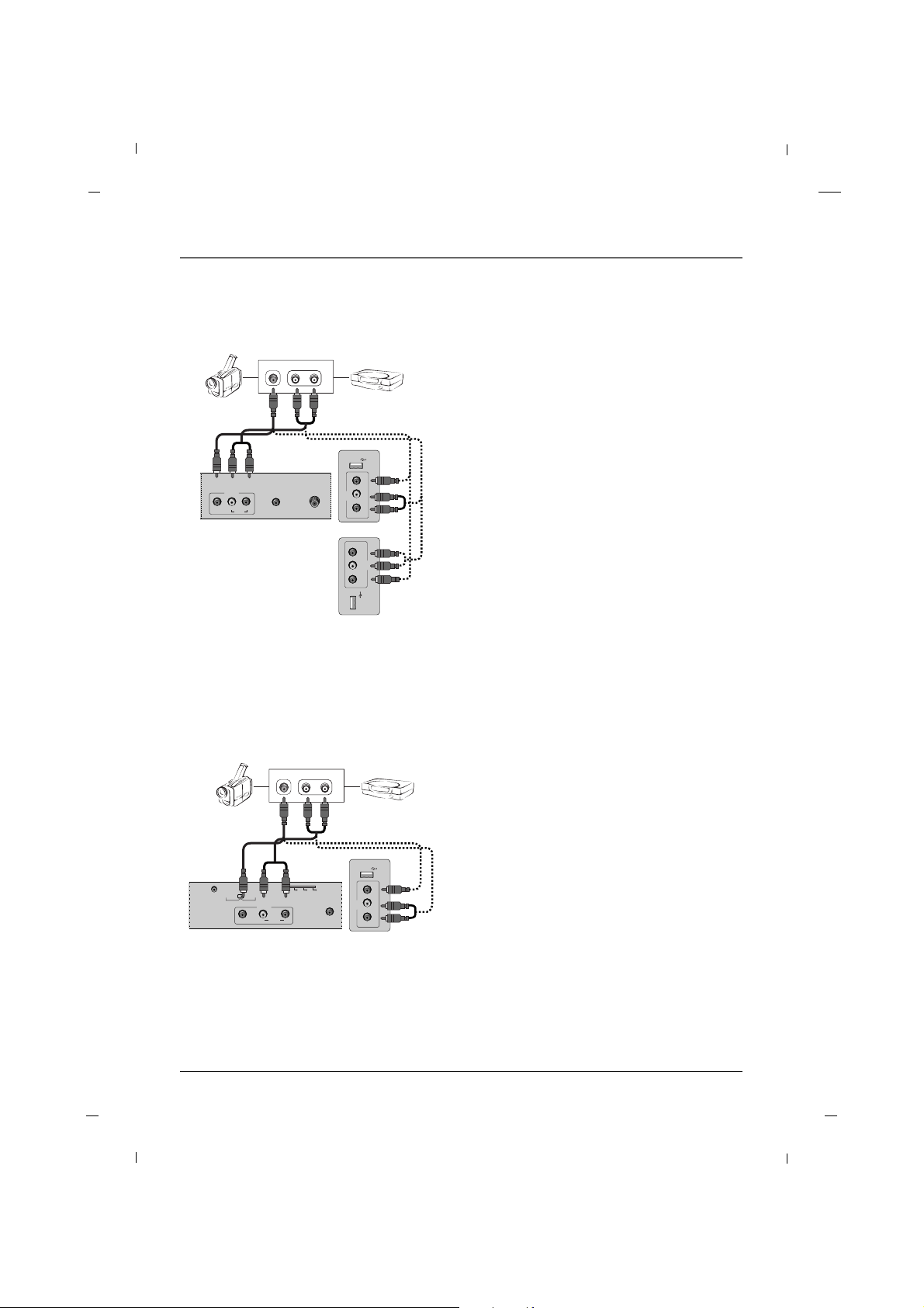
1. Connect the AUDIO/VIDEO jacks between TV and
external equipment. Match the jack colors (Video
= yellow, Audio Left = white, and Audio Right =
red)
2. Select the AV1 or AV2 input source using the
INPUT button on the remote control.
3. Operate the corresponding external equipment.
4. Refer to the external equipment manual for oper-
ating instructions.
Camcorder Video game set
External A/V Source - 26/32/42 inches
AUDIO IN
(RGB/DVI)
SERVICE
SPEAKER
SWITCH
PILLOW
SPEAKER
NORMAL
SPEAKER
AV1
AUDIO
L
VIDEO
R
ZEN PLS OFF RCA
VIDEO
L - AUDIO - R
AV2
USB IN
L-AUDIO-RVIDEO
OUT
1. Connect the AUDIO/VIDEO jacks between TV and
external equipment. Match the jack colors (Video
= yellow, Audio Left = white, and Audio Right =
red)
2. Select the AV1 or AV2 input source using the
INPUT button on the remote control.
3. Operate the corresponding external equipment.
4. Refer to the external equipment manual for oper-
ating instructions.
Camcorder Video game set
Rear panel of the set
External A/V Source - 22 inch
Side panel of the set
Chapter 1
Rear panel of the set
Side panel of
the set
26/32 inches
42 inch
Page 27

Chapter 1: Connections and Setup
27Chapter 1
Digital Audio Out - 22 inch
AUDIO IN
(RGB/DVI)
DIGITAL AUDIO
OUT(COAXIAL)
ANTENNA/
CABLE IN
PILLOW JACK IN
AUDIO
R
ZEN PLS OFF RCA
DIGITAL AUDIO
IN(COAXIAL)
1. Connect one end of the optical cable to the TV’s
DIGITAL AUDIO OUT(OPTICAL) port.
2. Connect the other end of the optical cable to the
digital audio input on the audio equipment.
3. Refer to the external audio equipment manual
for operation.
Audio Equipment
Rear panel of the set
Digital Audio Out - 26/32/42 inches
AUDIO IN
(RGB/DVI)
DIGITAL AUDIO
OUT(COAXIAL)
ANTENNA/
CABLE IN
AV1
AUDIO
L
VIDEO
R
DIGITAL AUDIO
IN(COAXIAL)
1. Connect one end of the optical cable to the TV’s
DIGITAL AUDIO OUT(OPTICAL) port.
2. Connect the other end of the optical cable to the
digital audio input on the audio equipment.
3. Refer to the external audio equipment manual
for operation.
Audio Equipment
Rear panel of the set
Page 28
Chapter 1: Connections and Setup
28
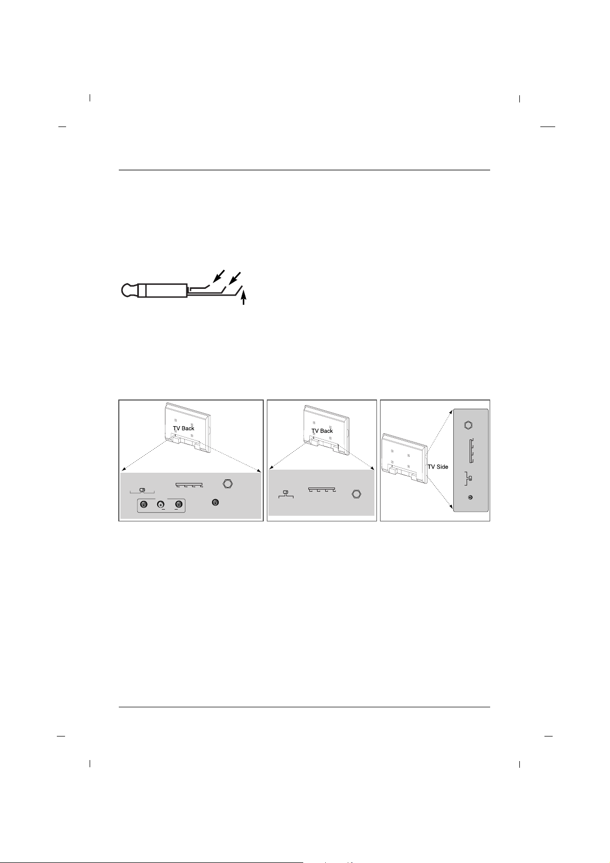
A 1/4” stereo style pillow speaker (pendant control) jack is located on the TV’s back panel.
A pin-out is provided below. The television will interface to many of the newer digital TV pillow speakers or
the older single button drycontact switch type. Use type SJ cord or better between the TV and the bedside
pendant control.
Pillow Speaker Wiring
SPEAKER
SWITCH
PILLOW
SPEAKER
NORMAL
SPEAKER
PILLOW JACK IN
ZEN PLS OFF RCA
TIP - Speaker
RING - Data
SLEEVE - Common
AUDIO IN
(RGB/DVI)
PILLOW JACK IN
SPEAKER
SWITCH
PILLOW
SPEAKER
NORMAL
SPEAKER
AV1
AUDIO
L
VIDEO
R
ZEN PLS OFF RCA
26/32 inches
22 inch
OPERATING THE TV
Connect the pillow speaker plug into the pillow speaker jack located on the back of the TV.
Single Button Pillow Speaker
• TV ON – Press the button once.
• CHANNEL UP – Press button once.
• TV OFF – Press and hold the button down.
TV will shut OFF in 3 seconds.
Digital Pillow Speaker
•Press the corresponding TV feature on the digital pillow speaker.
Normal/Pillow Switch
• Normal – TV audio plays through TV’s speaker.
• Pillow – TV audio plays through pillow speaker.
Selection switch – This switch selects the protocol logic level and the brand of IR Codes used by the pillow
speaker. User can choose between Philips
®
, Zenith®, or RCA
• ZEN : Zenith
®
protocol, +12V
• PLS : Philips
®
protocol, +5V
• OFF : Port Disabled
• RCA : RCA protocols, -5V
Zenith
®
is a trademark of Zenith Electronics LLC. Philips® is a trademark of Koninklijke Philips.
SERVICE
SPEAKER
SWITCH
PILLOW
SPEAKER
NORMAL
SPEAKER
PILLOW JACK IN
ZEN PLS OFF RCA
42 inch
Before Connecting Pillow Speaker:
To avoid over/reverse voltage to the device, make sure the pillow speaker selection switch is set to the correct
setting for the pillow speaker you are using.
Please refer to the “Selection Switch” item below for details on the switch settings.
Chapter 1
Digital
The pillow speaker common connects to the Sleeve,
speaker connects to the Tip, and data connects to
the Ring.
Single Button Analog
The single button switch closure should be wired
between Sleeve and Ring.
The speaker connects between the Sleeve and Tip.
Multiple Button Analog
Multiple button Analog pillow speakers are not supported by the television pillow speaker circuitry.
Contact RCA Commercial at 1-800-RCA-2161 for assistance with this type of pillow speaker.
Page 29
Chapter 1: Connections and Setup
29Chapter 1
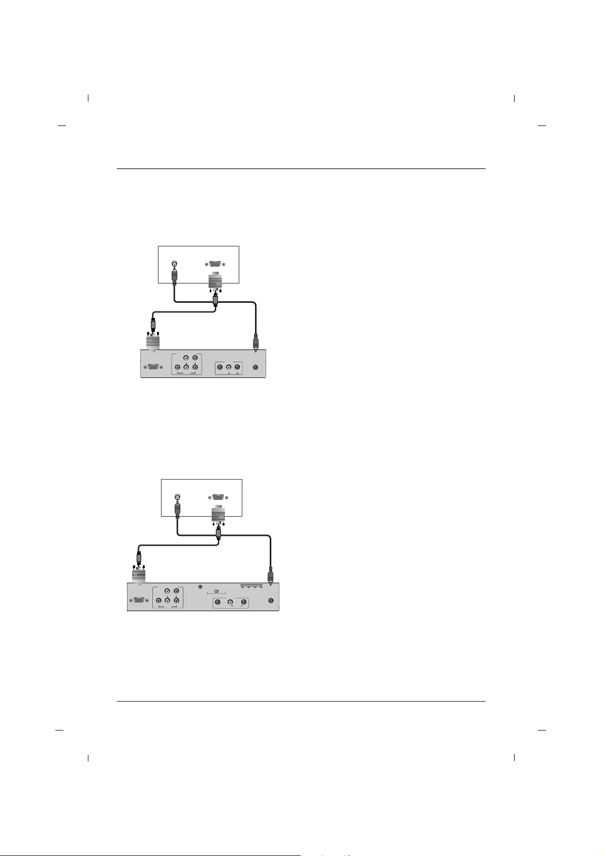
AA When connecting with a D-Sub 15 pin cable - 26/32/42 inches
RGB IN
(PC)
AUDIO IN
(RGB/DVI)
VIDEO
YPbPr
LR
COMPONENT IN
AUDIO
AV1
AUDIO
L
VIDEO
R
AUDIO OUT PC OUTPUT
1. Connect the RGB output of the PC to the RGB IN
(PC) jack on the set.
2. Connect the PC Audio Output to the AUDIO IN
(RGB/DVI) jack on the TV using a male-to-male
3.5mm mini jack.
3. Turn on both the PC and TV.
4. Select the VGA input source on your TV by pressing either the INPUT buttons on the remote control.
PC
Rear panel of the set
PC Connection
AA When connecting with a D-Sub 15 pin cable - 22 inch
RGB IN
(PC)
AUDIO IN
(RGB/DVI)
VIDEO
YPbPr
LR
COMPONENT IN
AUDIO
SERVICE
SPEAKER
SWITCH
PILLOW
SPEAKER
NORMAL
SPEAKER
AV1
AUDIO
L
VIDEO
R
ZEN PLS OFF RCA
AUDIO OUT PC OUTPUT
1. Connect the RGB output of the PC to the RGB IN
(PC) jack on the set.
2. Connect the PC Audio Output to the AUDIO IN
(RGB/DVI) jack on the TV using a male-to-male
3.5mm mini jack.
3. Turn on both the PC and TV.
4. Select the VGA input source on your TV by pressing either the INPUT buttons on the remote control.
PC
Rear panel of the set
Page 30
Chapter 1: Connections and Setup
30
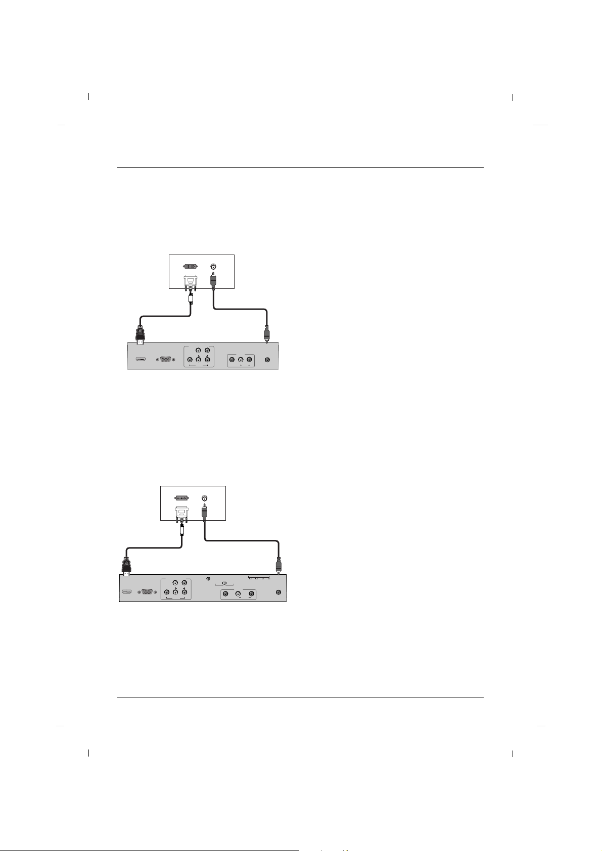
AA When connecting with a HDMI to DVI cable - 26/32/42 inches
HDMI/DVIINRGB IN
(PC)
AUDIO IN
(RGB/DVI)
VIDEO
YPbPr
LR
COMPONENT IN
AUDIO
AV1
AUDIO
L
VIDEO
R
DVI OUTPUT
AUDIO OUT
1. Connect the DVI Output on the PC to the
HDMI / DVI IN Input jack on the TV.
2. Connect the PC Audio Output to the AUDIO IN
(RGB/DVI) jack on the TV using a male-to-male
3.5mm mini jack.
3. Turn on both the PC and TV.
4. Select the HDMI input source on your TV by press-
ing either the INPUT buttons on the remote control.
PC
Rear panel of the set
AA When connecting with a HDMI to DVI cable - 22 inch
HDMI/DVIINRGB IN
(PC)
AUDIO IN
(RGB/DVI)
VIDEO
YPbPr
LR
COMPONENT IN
AUDIO
SERVICE
SPEAKER
SWITCH
PILLOW
SPEAKER
NORMAL
SPEAKER
AV1
AUDIO
L
VIDEO
R
ZEN PLS OFF RCA
DVI OUTPUT
AUDIO OUT
1. Connect the DVI Output on the PC to the
HDMI / DVI IN Input jack on the TV.
2. Connect the PC Audio Output to the AUDIO IN
(RGB/DVI) jack on the TV using a male-to-male
3.5mm mini jack.
3. Turn on both the PC and TV.
4. Select the HDMI input source on your TV by press-
ing either the INPUT buttons on the remote control.
PC
Rear panel of the set
Chapter 1
Page 31

Chapter 1: Connections and Setup
31Chapter 1
31.47
35.16
37.88
48.36
59.94
56.25
60.32
60.00
Horizontal
Frequency (kHz)
Vertical
Frequency (Hz)
640 x 480
800 x 600
1024 x 768
Resolution
AA PC
60.000
60.000
60.000
60.000
Vertical
Frequency (Hz)
480/60P
720/60P
1080/60I
1080/60P
Resolution
AA HDMI
Resolution
Note
a. The synchronization input form is separate.
b. If the resolution is not supported, ‘Not Support!’ message will be displayed.
Page 32

Chapter 1: Connections and Setup
32
1. Connect the USB device to the USB IN jack
on the set.
2. Select the USB input source using the
INPUT button on the remote control.
3. Follow the on screen display to access the
USB functions.
USB Port
Headphone - 22inch
VIDEO
L - AUDIO - R
AV2
H/P
USB IN
1. Insert the headphone plug to the headphone
socket of the set.
2. You can listen to the sound through the headphone.
3. To adjust the headphone volume, press the
VOL+ / VOL- button.
Control the volume of the headphone to the
appropriate level.
Listening for a long time with the volume set too
high may cause permanent damage to your hearing.
Side panel of the set
Chapter 1
AV2
VIDEO L - AUDIO - R
USB IN
VIDEO
L - AUDIO - R
AV2
H/P
USB IN
R - AUDIO - L
AV2
VIDEO
USB IN
USB Memory
USB Memory
USB Memory
Side panel
of the set
Side panel
of the set
Side panel
of the set
26/32
inches
22 inch 42 inch
Page 33

33Chapter 2
Chapter 2: Using the Remote Control
The basic remote control (R130K1) is used by the viewer for basic operating functions. It is designed so that
the viewer cannot alter certain master remote-specified features. The Sleep, Closed Captioning, and Channel
Guide features can be accessed directly with remote buttons.
1. NUMBER BUTTONS
Selects channel numbers.
2. ON-OFF
Switches the set on or off.
3. SYSTEM
Configures the remote for TV1/TV2.
Configures the remote preamble (Bed 1/Bed 2) for use
with multi TVs in 1 room.
Press and hold <SYSTEM> and <1> key to set remote for
“Bed1”(TV1).
Press and hold <SYSTEM> and <2> key to set the remote
for “Bed2”(TV2). Refer to “Key Management”,”RCU type”
in Chapter 5.
4. SOUND
Recalls your preferred sound setting.
5. SKIP
Unused
6. SLEEP
Sets the sleep timer.
7. GUIDE
Display “Channel List” menu.
8. GO BACK
Return to the previous menu.
9. CC
Select the Caption menu directly.
10. VOL + / VOL -
Adjusts sound level.
CH + / CH -
Select a channel.
MUTE
Switches the sound on or off.
11. INPUT
Selects the TV, AV1, AV2, YPbPr, VGA, HDMI or USB
mode.
12. ANTENNA
Unused
13. MENU
Displays “Basic” on screen menu.
There are 2 remotes for this TV;
R130K1 - user Remote. This remote displays a basic user
menu when the menu key is pressed.
R130K2 - installer Remote. This remote displays an
installer menu when the menu key is pressed.
14. Navigational Controls
Adjusts menu settings.
Selects menu item.
15. OK
Accepts your selection.
16. INFO
Display the current channel information.
17. CLEAR
Exit from any OSD.
1 2 3
4 5 6
7 8 9
0
SYSTEM
GUIDESLEEPSKIP
CCGO BACK
ANTENNAINPUT
SOUND
MENU OK INFO
CLEAR
MUTE
CH
VOL VOL
CH
ON-OFF
C O M M E R C I A L
R130K1
1
5
8
10
11
2
3
4
6
9
12
7
Basic(User) Remote
15
16
17
13
14
Page 34

Chapter 2: Using the Remote Control
34
1. NUMBER BUTTONS
Selects channel numbers.
2. ON-OFF
Switches the set on or off.
3. SYSTEM
Configures the remote for TV1/TV2.
Configures the remote preamble (Bed 1/Bed 2) for use
with multi TVs in 1 room.
Press and hold <SYSTEM> and <1> key to set remote for
“Bed1”.
Press and hold <SYSTEM> and <2> key to set the remote
for “Bed2”. Refer to “Key Management”,”RCU type” in
Chapter 5.
4. RESET
Unused.
5. SKIP
Unused
6. SLEEP
Sets the sleep timer.
7. GUIDE
Display “Channel List” menu.
8. GO BACK
Return to the previous menu.
9. CC
Select the Caption menu directly.
10. VOL + / VOL -
Adjusts sound level.
CH + / CH -
Select a channel.
MUTE
Switches the sound on or off.
11. INPUT
Selects the TV, AV1, AV2, YPbPr, VGA, HDMI or USB
mode.
12. ANTENNA
Unused
13. MENU
Displays “Installer” on screen menu.
There are 2 remotes for this TV;
R130K1 - user Remote. This remote displays a basic user
menu when the menu key is pressed.
R130K2 - installer Remote. This remote displays an
installer menu when the menu key is pressed.
14. Navigational Controls
Adjusts menu settings.
Selects menu item.
15. OK
Accepts your selection.
16. INFO
Display the current channel information.
17. CLEAR
Exit from any OSD.
1 2 3
4 5 6
7 8 9
0
SYSTEM
GUIDESLEEPSKIP
CCGO BACK
ANTENNAINPUT
RESET
MENU OK INFO
CLEAR
MUTE
CH
VOL VOL
CH
ON-OFF
R130K2
MASTER
• Remove the battery compartment cover
from the back of the remote by pushing
the tab and lifting off the cover.
• Insert two fresh batteries. Make sure the
polarities (+ and -) are aligned correctly.
• Replace the cover.
Put Batteries in the Remote
The master remote control (R130K2) accesses all of the TV’s menus. It is used to customize the TV’s functionality for specific users or specific situations.
Master(Installer) Remote
1
5
8
10
11
2
3
4
6
9
12
7
15
16
17
13
14
Chapter 2
Page 35

35Chapter 3
Chapter 3: Using USB Clone Tool
USB Cloner Operation
1. USB Connector
Connects to the USB port of the TV or PC.
2. Service Port
Connects to the service port of the television. See “Learning” section for details.
3. Mode Switch
Mode Selection Switch.
4. Status LED
Shows the status of the USB Clone.
5. Learn Button
Button to start the “learn” process. See “learning” section for details.
1
4
5
2
3
Teaching
Learning
Errors Table
Flashing Red/Green LED indicates the following error conditions.
Error Detected in TV Channel list file.
Error in transmission Data Packet
No response from service port.
Couldn’t save TV settings to USB Cloner
1
2
3
4
4
5
6
10
Number of Green
LED Flashes
Page 36

Chapter 3: Using USB Clone Tool
36
Learning - 22inch
AUDIO IN
(RGB/DVI)
ANTENNA/
CABLE IN
SERVICE
PILLOW JACK IN
SPEAKER
SWITCH
PILLOW
SPEAKER
NORMAL
SPEAKER
AV1
AUDIO
L
VIDEO
R
ZEN PLS OFF RCA
VIDEO
L
AV2
R
H/P
USB IN
Teaching
Learning
Rear panel of the set
Side panel
of the set
2.5mm Stereo Cable
(cross data cable)
USB Cloner
1. Turn TV on.
2. Connect USB Cloner to TV USB Port.
3. Set switch to “learning” position.
(Status LED will Light red without flashing.)
4. Connect 2.5mm Stereo Cable (cross data cable)
between the TV service port and the USB Cloner
service port.
5. Press the Learn button for 1 second. As soon as
the LED turns green, release the button.
6. The LED will turn Red and flash while the settings
are being saved to the USB Key. Upon successful
copy, the LED will light up yellow for 2 seconds
and then return to a red, constantly lit state.
Upon an unsuccessful copy, the LED will flash an
error code as described in the “Error Table” section.
Note : New TV Settings file, “ChList.bin” will appear
on the USB Cloner .
Learning - 26/32 inches
1. Turn TV on.
2. Connect USB Cloner to TV USB Port.
3. Set switch to “learning” position.
(Status LED will Light red without flashing.)
4. Connect 2.5mm Stereo Cable (cross data cable)
between the TV service port and the USB Cloner
service port.
5. Press the Learn button for 1 second. As soon as
the LED turns green, release the button.
6. The LED will turn Red and flash while the settings
are being saved to the USB Key. Upon successful
copy, the LED will light up yellow for 2 seconds
and then return to a red, constantly lit state.
Upon an unsuccessful copy, the LED will flash an
error code as described in the “Error Table” section.
Note : New TV Settings file, “ChList.bin” will appear
on the USB Cloner .
DIGITAL AUDIO
OUT(COAXIAL)
SERVICE
SPEAKER
SWITCH
PILLOW
SPEAKER
NORMAL
SPEAKER
PILLOW JACK IN
ZEN PLS OFF RCA
R
L
AV2
VIDEO
USB IN
Teaching
Learning
Rear panel of the set
Side panel
of the set
2.5mm Stereo
Cable (cross
data cable)
USB Cloner
Chapter 3
Copying settings out of TV.
Copying settings out of TV.
Page 37

37
Chapter 3: Using USB Clone Tool
Chapter 3
SERVICE
SPEAKER
SWITCH
PILLOW
SPEAKER
NORMAL
SPEAKER
PILLOW JACK IN
ZEN PLS OFF RCA
Learning
Teaching
AV2
VIDEO L - AUDIO - R
USB IN
Side panel of
the set
Side panel of
the set
2.5mm Stereo Cable
(cross data cable)
USB Cloner
Learning - 42inch
1. Turn TV on.
2. Connect USB Cloner to TV USB Port.
3. Set switch to “learning” position.
(Status LED will Light red without flashing.)
4. Connect 2.5mm Stereo Cable (cross data cable)
between the TV service port and the USB Cloner
service port.
5. Press the Learn button for 1 second. As soon as
the LED turns green, release the button.
6. The LED will turn Red and flash while the settings
are being saved to the USB Key. Upon successful
copy, the LED will light up yellow for 2 seconds
and then return to a red, constantly lit state.
Upon an unsuccessful copy, the LED will flash an
error code as described in the “Error Table” section.
Note : New TV Settings file, “ChList.bin” will appear
on the USB Cloner .
Teaching
1. Connect USB Cloner to TV USB Port.
2. Set mode switch to “teach”.
(Status LED will flash red)
3. Unplug the TV from the power outlet.
4. Plug the TV back into the power outlet.
TV settings will be copied into television.
Note : TV Settings file “ChList.bin” should be present
on USB clone device for teaching function to
work properly. Refer to “Learning” section for
details.
Copying settings out of TV.
Placing settings into TV.
AV2
VIDEO L - AUDIO - R
USB IN
Teaching
Learning
VIDEO
L
AV2
R
H/P
USB IN
Teaching
Learning
Side panel
of the set
Side panel
of the set
USB Cloner
USB Cloner
22/26/32 inches 42 inch
Page 38

38 Chapter 4
Chapter 4: Basic Operation
Plug the end of the power cord into the back of the TV. Plug the other end into a grounded wall outlet.
Insert the plug completely into the outlet. Do not plug into an outlet controlled by a light switch.
Plug in the TV
Turn on your TV by pressing the Power button on the front of the TV or ON-OFF on the remote control.
Turn on the TV
This function automatically finds all channels available through the Antenna or Cable and stores them in
memory on the channel list.
Channel Scans can only be performed using a Master remote.
Channel Scan
You can select a channel number with the CH + / CH - button or NUMBER buttons.
Channel Selection
Press the VOL+ / VOL- button to adjust the sound level.
Volume Adjustment
Press the MUTE button. The sound is switched off and the mute Icon appears.
To cancel mute mode, press the MUTE or VOL+ / VOL- button again.
Sound Mute
Page 39

39Chapter 4
Chapter 4: Basic Operation
1. Press the INPUT button to change the input
mode.
2. Press the Down or Up button to select your
desired mode.
3. Press the OK button to change your selected
mode.
Source Selection
1. Press the MENU button and then press the Down or
Up button to select the Setup.
2. Press the OK button and then press the Down or Up
button to select OSD Language.
3. Press the Left or Right button to select your desired
language.
(Select between English, Español, Français)
4. The on screen menu will then appear in the selected
language.
Language Selection
Input Source
TV
AV1
AV2
YPbPr
VGA
HDMI
USB
OSD Language
Screen Mode
Time Setup
Caption
Reset Default
English
Normal
FF GG
FF GG
GG
GG
GG
Setup
MENU
ExitSelect
Page 40

40 Chapter 5
Chapter 5: Commercial Interface Menus
Commercial Interface
OnCommercial Interface
Channel
OSD
Source
Volume
Pillow Speaker
Power Management
RCU and Local Key
Reset Commercial Interface
MENU
Exit
ENTER
Enter Select
FF GG
GG
GG
GG
GG
GG
GG
GG
GG
-You must set “Commercial Interface” to “On” to activate the below items.
Commercial Interface
OnCommercial Interface
Channel
OSD
Source
Volume
Pillow Speaker
Power Management
RCU and Local Key
Reset Commercial Interface
MENU
Exit
ENTER
Enter Select
FF GG
GG
GG
GG
GG
GG
GG
GG
GG
Commercial Interface
On
Virtual
Off
Off
Direct Tuning Access
ATSC Tune Mode
Power On Source
Power On Major Channel
Power On Miner Channel
Channel Hold
MENU
BackSelect
FF GG
FF GG
FF GG
2
0
FF GG
Channel
These TVs include a full commercial interface that allows your facility to customize the performence to your specific needs. These settings are only accessible to the installer with the use of
the Master Remote(R130K2). Contact your RCA Commercial Distribution to obtain a master
remote.
You can access this menu by pressing MENU -> 9 -> 6 -> 3 -> 2 using the Master Remote.
Commercial Interface
OnCommercial Interface
Channel
OSD
Source
Volume
Pillow Speaker
Power Management
RCU and Local Key
Reset Commercial Interface
MENU
Exit
ENTER
Enter Select
FF GG
GG
GG
GG
GG
GG
GG
GG
GG
Commercial Interface
On
60S
On
Channel Banner
OSD Timer
Clear V-Chip
MENU
BackSelect
FF GG
FF GG
FF GG
- Channel Banner : If this function is off then channel banner will not appear when channel is changed.
- OSD Timer : Use this setting to configure the menu OSD time out.
- Clear V-Chip : This function can be used to Clear V-Chip password and settings.
OSD
- Direct Tuning Access : If this function is on, you can tune to channels even if the channels are not in the
channel list using the numeric keys. If this function is off, only channels in the channel list can be tuned.
-ATSC Tune Mode : This function sets the channel frequency type for Digital Channels to physical or virtual.
If the facility has a head end signal distribution system, set this to “physical”.
- Power On Source : Use this setting to configure the signal source of the TV when it is turned on.
- Power On Major/Minor Channel : Use this setting to configure the initial channel of the TV when it is
turned on.
Note: “Power On Source” should be set to “TV” to use this setting.
To tune to an analog channel, set minor channel to 0.
- Channel Hold : If this function is on then you cannot change channels.
Page 41

Chapter 5: Commercial Interface Menus
41Chapter 5
Commercial Interface
Input Block
AUX Inputs
MENU
BackSelect
GG
GG
Commercial Interface
TV
AV
S-Video
YPBPR
VGA
HDMI
USB
1
2
3
4
5
6
7
MENU
BackSelect
- Input Block : Use this setting to configure which inputs are available to the user through the input button.
Source
Commercial Interface
Off
Off
Off
Off
Off
Off
AV
S-Video
YPBPR
VGA
HDMI
USB
MENU
ExitSelect
FF GG
FF GG
FF GG
FF GG
FF GG
FF GG
Commercial Interface
Input Block
AUX Inputs
MENU
BackSelect
GG
GG
- AUX Inputs : Use this setting to place inputs into the channel list. If you place an input in the channel list,
the user can access the input using the CH buttons on the remote and Pillow Speaker.
ENTER
Set
Commercial Interface
OnCommercial Interface
Channel
OSD
Source
Volume
Pillow Speaker
Power Management
RCU and Local Key
Reset Commercial Interface
MENU
Exit
ENTER
Enter Select
FF GG
GG
GG
GG
GG
GG
GG
GG
GG
- Initial Volume : This setting configures the turn on volume of the TV.
- Min Volume : This setting assigns the minimum volume level that the user can access.
- Max Volume : This setting assigns the maximum volume level that the user can access.
-Volume Hold : If this function is on then user cannot adjust volume level
- Blank and Mute : If this function is on, sound will be muted when video is not present on the external
video source.
Volume
Commercial Interface
Off
Off
Initial Volume
Min Volume
Max Volume
Volume Hold
Blank and Mute
MENU
BackSelect
30
0
0
FF GG
FF GG
ENTER
Adjust
Note
Initial / Max / Min volume settings only apply when the speaker switch is set to “Normal Speaker”.
When the switch is set to “Pillow Speaker”, max volume is forced 50% to prevent damage to pillow speaker
audio circuit.”
Page 42

42 Chapter 5
Chapter 5: Commercial Interface Menus
Commercial Interface
OnCommercial Interface
Channel
OSD
Source
Volume
Pillow Speaker
Power Management
RCU and Local Key
Reset Commercial Interface
MENU
Exit
ENTER
Enter Select
FF GG
GG
GG
GG
GG
GG
GG
GG
GG
- CH Hold : If this function is on then TV will turn off when CH key is held for 4 seconds on an analog pillow
speaker.
- Power Off in Channel List : If this function is on then TV will turn off when CH+ key is pressed on last
channel
Pillow Speaker
Commercial Interface
Off
Off
CH Hold
Power Off in Channel List
MENU
BackSelect
FF GG
FF GG
Commercial Interface
OnCommercial Interface
Channel
OSD
Source
Volume
Pillow Speaker
Power Management
RCU and Local Key
Reset Commercial Interface
MENU
Exit
ENTER
Enter Select
FF GG
GG
GG
GG
GG
GG
GG
GG
GG
Power Management
Commercial Interface
Off
Off
Off
Auto Power On
Auto Power Off
Power Always On
MENU
BackSelect
FF GG
FF GG
FF GG
Commercial Interface
OnCommercial Interface
Channel
OSD
Source
Volume
Pillow Speaker
Power Management
RCU and Local Key
Reset Commercial Interface
MENU
Exit
ENTER
Enter Select
FF GG
GG
GG
GG
GG
GG
GG
GG
GG
- Key Lock : This setting disables the keys on the front of the TV.
- RCU Type : This function assigns RCU type as TV1, TV2. This is used when more than 1 TV is being installed
in the same room.
Note : The remote must be configured to send the matching RCU Type corresponding to this setting.
This is done as follows : On the R130 K1 remote, press hold <SYSTEM> and <1> keys for 5 seconds to set it
to “TV1”. Press and hold <SYSTEM> and <2> keys for 5 seconds to set it to “TV2”.
Key Management
Commercial Interface
On
TV1
Key Lock
IR(RCU) Type
MENU
BackSelect
FF GG
FF GG
- Auto Power On : This function sets the power state when AC power is applied to the TV.
+ Off : TV will go to stanby mode
+ On : TV will turn on
+ Last : TV will resume the state it was in before AC power was removed.
- Auto Power Off : This function assigns the amount of time an inactive TV will remain on. It can be used by
your facility to save energy.
- Power Always On : TV can not be turned off.
Page 43

Chapter 5: Commercial Interface Menus
43Chapter 5
Commercial Interface
OnCommercial Interface
Channel
OSD
Source
Volume
Pillow Speaker
Power Management
RCU and Local Key
Reset Commercial Interface
MENU
Exit
ENTER
Enter Select
FF GG
GG
GG
GG
GG
GG
GG
GG
GG
- This function will reset all data in the commercial interface menu to the factory defaults.
Reset Commercial Reset
Reset Commecial Reset
OK Cancel
Page 44

44 Chapter 6
Chapter 6: Using the TV's Features
Your TV’s OSD(On Screen Display) may differ slightly from what is shown in this manual.
1. Press the MENU button and then press the Down or Up button to select each menu.
2. Press the OK button and then Down, Up, Left and Right buttons to navigate to the available menus.
Video MENU Audio MENU
Parental MENU
Setup MENU
TV MENU
Tuner Mode
Channel Scan
Channel Skip
Cable
FF GG
GG
GG
TV
MENU
Exit
ENTER
Enter Select
Video
User
Middle
FF GG
45
50
50
0
0
FF GG
GG
GG
GG
Picture Mode
Brightness
Contrast
Saturation
HUE
Sharpness
Gamma
Color Temperature
Advanced Video
Reset Picture Mode
MENU
Exit
ENTER
Enter Select
Audio
Balance
Bass
Treble
Sound Surround
Sound Mode
Equalizer
SPDIF Type
MTS
Audio Language
0
40
40
FF GG
FF GG
FF GG
FF GG
FF GG
FF GG
On
Off
Off
PCM
Stereo
English
MENU
Exit
ENTER
Enter Select
OSD Language
Screen Mode
Time Setup
Caption
Reset Default
English
Normal
FF GG
FF GG
GG
GG
GG
Setup
ENTER
Enter
MENU
ExitSelect
Parental
Program Block
Change Password
Clean All
GG
GG
GG
ENTER
Enter
MENU
ExitSelect
On Screen Menus
Page 45

Chapter 6: Using the TV's Features
45Chapter 6
Setting up the TV Channel
This function automatically finds all channels available through the Antenna or Cable and stores them in
memory as the channel list.
Auto Scan
1. Press the MENU button on the master remote to
enter the on-screen menu and then press either the
Down or Up button to select the TV sub-menu.
2. Press the OK button to enter the sub-menu and
then press either the Down or Up button to select
Tuner Mode.
3. Press the Left or Right button to select either
Antenna or Cable.
4. Press the Down or Up button to select Channel
Scan.
5. Press the OK button to start the auto search.
The TV will begin memorizing all of the available
channels.
6. Press the MENU button at any time to exit the channel scan process.
7. Once the channel scan is complete the channels
found and recognized by the TV will be available for
viewing.
TV
Tuner Mode
Channel Scan
Channel Skip
Cable
FF GG
GG
GG
TV
Status:Scanning.. Cable
Analog Channels:1
Digital Channels:0
10%
Tuner Mode
Channel Scan
Channel Skip
Cable
FF GG
GG
GG
TV
ENTER
Scan
MENU
ExitSelect
MENU
BackSelect
MENU
Cancel
This TV prevents the user from changing the channel list.
Note : Some of these menu items can only be accessed using the Master Remote(R130K2).
Page 46

Chapter 6: Using the TV's Features
46 Chapter 6
You can manually store or remove channels in whatever order you desire.
Add / Delete a Channel
1. Press the MENU button on the master remote to
enter the on-screen menu and then press either the
Down or Up button to select the TV sub-menu.
2. Press the OK button to enter the sub-menu and
then press either the Down or Up button to select
Channel Skip.
3. Press the OK button and then press the Down or
Up button to select channel you want to add or
delete.
If you want to skip the selected channel, press the
OK button to uncheck your selection.
4. All channels that have a check will be added to your
viewing selection.
5. Press the MENU button to return to the previous
menu.
Channel Skip
1 Analog
2 Analog
3 Analog
4 Analog
5 Analog
6 Analog
7 Analog
8 Analog
9 Analog
Tuner Mode
Channel Scan
Channel Skip
Cable
FF GG
GG
GG
TV
ENTER
Enter
MENU
ExitSelect
ENTER
Set
MENU
BackSelect
Page 47

47Chapter 6
Chapter 6: Using the TV's Features
Adjusting The Picture Controls
1. Press the MENU button to enter the on-screen
menu and then press either the Down or Up button
to select the Video sub-menu.
2. Press the OK button to enter the sub-menu and
then press either the Down or Up button to select
Picture Mode.
3. Press the Left or Right button to select between
Cinema, Sport, Vivid, Hi-Bright or User Picture
Modes.
4. Press the MENU button to return to the previous
menu.
The various Picture Modes allow you to adjust the display to your viewing preference.
Picture Controls
Video
User
Middle
FF GG
45
50
50
0
0
FF GG
GG
GG
GG
Picture Mode
Brightness
Contrast
Saturation
HUE
Sharpness
Gamma
Color Temperature
Advanced Video
Reset Picture Mode
MENU
ExitSelect
Page 48

48
Chapter 6: Using the TV's Features
Chapter 6
Manual Picture Controls
1. Press the MENU button to enter the on-screen
menu and then press either the Down or Up button
to select the Video sub-menu.
2. Press the OK button to enter the sub-menu and use
the Left or Right button to change the picture
mode to User. Then, press either the Down or Up
button to scroll to the desired picture option.
(Brightness, Contrast, Saturation, HUE,
Sharpness)
3. Press the OK button and then use the Left or Right
button to adjust the selection to your preference.
4. Press the MENU button to return to the previous
menu.
You can adjust picture Brightness, Contrast, Saturation, HUE and Sharpness to the levels you prefer.
• Brightness
Increases or decreases amount of white in the your
picture.
• Contrast
Adjusts the difference between the light and dark
levels in the picture.
• Saturation
Adjusts intensity of all colors.
• HUE
Adjusts the balance between red and green levels.
• Sharpness
Adjusts the level of sharpness in the edges between
the light and dark areas of the picture. The lower
the level, the softer the image.
Brightness 60
Video
User
Middle
FF GG
45
50
50
0
0
FF GG
GG
GG
GG
Picture Mode
Brightness
Contrast
Saturation
HUE
Sharpness
Gamma
Color Temperature
Advanced Video
Reset Picture Mode
MENU
ExitSelect
ENTER
Adjust
Page 49

49
Chapter 6: Using the TV's Features
Chapter 6
Video
User
Middle
FF GG
45
50
50
0
0
FF GG
GG
GG
GG
Picture Mode
Brightness
Contrast
Saturation
HUE
Sharpness
Gamma
Color Temperature
Advanced Video
Reset Picture Mode
MENU
ExitSelect
Gamma
1. Press the MENU button to enter the on-screen
menu and then press either the Down or Up button
to select the Video sub-menu.
2. Press the OK button to enter the sub-menu and
then press either the Down or Up button to select
Gamma.
3. Press the Left or Right button to select between
Dark, Middle or Bright.
4. Press the MENU button to return to the previous
menu.
This feature will allow you to adjust the brightness curve for the display.
Page 50

50
Chapter 6: Using the TV's Features
Chapter 6
Color Temperature
1. Press the MENU button to enter the on-screen
menu and then press either the Down or Up button
to select the Video sub-menu.
2. Press the OK button to enter the sub-menu and
then press either the Down or Up button to select
and enter into the Color Temperature submenu.
3. Press the OK button and then press the Left or
Right button to select between Cool, Standard,
Warm or User settings.
4. If you selected the User setting, press the Down or
Up button to select desired color option you wish to
adjust.
5. Press the OK button and then use the Left or Right
button to make appropriate adjustments.
6. Press the MENU button to return to the previous
menu.
The Color Temperature settings will allow you to adjust the lighting in the display to compliment your viewing preference.
The Cool setting will add more Blues and Greens into the image to give it a “cooler ” feeling.
The Warm setting will add more Reds and Yellows into the image to give it a “warmer ” feeling.
The Standard setting will be a more natural feeling and will fall between the Cool and Warm settings.
Color Temperature
Color Temperature
R Gain
G Gain
B Gain
Standard
FF GG
0
0
0
R Gain 0
MENU
BackSelect
Note
-To adjust manually Color Temperature on your display, change the Color Temperature Mode to User.
Video
User
Middle
FF GG
45
50
50
0
0
FF GG
GG
GG
GG
Picture Mode
Brightness
Contrast
Saturation
HUE
Sharpness
Gamma
Color Temperature
Advanced Video
Reset Picture Mode
MENU
ExitSelect
Page 51

51
Chapter 6: Using the TV's Features
Chapter 6
When changing your settings, you can select the Reset Picture Mode option to restore the previous
settings.
Reset Picture Mode
1. Press the MENU button to enter the on-screen
menu and then press either the Down or Up button
to select the Video sub-menu.
2. Press the OK button to enter the sub-menu and use
the Down or Up button to select Reset Picture
Mode.
3. Once the confirmation window appears, press OK to
restore the previous settings.
Are you sure?
OK Cancel
Video
User
Middle
FF GG
45
50
50
0
0
FF GG
GG
GG
GG
Picture Mode
Brightness
Contrast
Saturation
HUE
Sharpness
Gamma
Color Temperature
Advanced Video
Reset Picture Mode
MENU
ExitSelect
ENTER
Enter
Page 52

52
Dynamic Noise Reduction
1. Press the MENU button to enter the on-screen menu
and then press either the Down or Up button to
select the Video sub-menu.
2. Press the OK button to enter the sub-menu and then
press either the Down or Up button to select
Advanced Video.
3. Press the OK button to enter the submenu and then
press the Down or Up button to select DNR.
4. Press the Left or Right button to select between
Off, Low, Medium, Strong or Auto.
5. Press the MENU button to return to the previous
menu.
Use this feature to reduce the amount of noise, or film grain, that may be present in the picture.
Advanced Video
• Off
Turns the screen noise reduction function off.
• Low
Reduces screen noise at a low level.
• Medium
Reduces screen noise at a medium level.
• Strong
Reduces screen noise at a high level.
• Auto
Automatically adjusts the noise reduction level
according to received signal.
Advanced Video
DNR
CTI
Flesh Tone
Adaptive Luma Control
Blue Mute
Back Light
Medium
Medium
On
On
On
FF GG
FF GG
FF GG
FF GG
FF GG
50
MENU
BackSelect
Video
User
Middle
FF GG
45
50
50
0
0
FF GG
GG
GG
GG
Picture Mode
Brightness
Contrast
Saturation
HUE
Sharpness
Gamma
Color Temperature
Advanced Video
Reset Picture Mode
MENU
ExitSelect
ENTER
Enter
Chapter 6: Using the TV's Features
Chapter 6
Page 53

53
Chapter 6: Using the TV's Features
Chapter 6
CTI (Color Transient Intensity)
1. Press the MENU button to enter the on-screen
menu and then press either the Down or Up button
to select the Video sub-menu.
2. Press the OK button to enter the sub-menu and
then press either the Down or Up button to select
Advanced Video.
3. Press the OK button and then press the Down or
Up button to select CTI.
4. Press the Left or Right button to select Off, Low,
Medium or Strong.
5. Press the MENU button to return to the previous
menu.
This feature is used to reduce the time the display takes to transition from one color to another.
The effect of CTI will be seen as sharpening the border between colors.
Flesh Tone
1. Press the MENU button to enter the on-screen
menu and then press either the Down or Up button
to select the Video sub-menu.
2. Press the OK button to enter the sub-menu and
then press either the Down or Up button to select
Advanced Video.
3. Press the OK button and then press the Down or
Up button to select Flesh Tone.
4. Press the Left or Right button to select On or Off.
5. Press the MENU button to return to the previous
menu.
In some cases, activation of this feature can result in a more pleasing display of sky and flesh colors.
Advanced Video
DNR
CTI
Flesh Tone
Adaptive Luma Control
Blue Mute
Back Light
Medium
Medium
On
On
On
FF GG
FF GG
FF GG
FF GG
FF GG
50
MENU
BackSelect
Advanced Video
DNR
CTI
Flesh Tone
Adaptive Luma Control
Blue Mute
Back Light
Medium
Medium
On
On
On
FF GG
FF GG
FF GG
FF GG
FF GG
50
MENU
BackSelect
Video
User
Middle
FF GG
45
50
50
0
0
FF GG
GG
GG
GG
Picture Mode
Brightness
Contrast
Saturation
HUE
Sharpness
Gamma
Color Temperature
Advanced Video
Reset Picture Mode
MENU
ExitSelect
ENTER
Enter
Video
User
Middle
FF GG
45
50
50
0
0
FF GG
GG
GG
GG
Picture Mode
Brightness
Contrast
Saturation
HUE
Sharpness
Gamma
Color Temperature
Advanced Video
Reset Picture Mode
MENU
ExitSelect
ENTER
Enter
Page 54

54
Advanced Video
DNR
CTI
Flesh Tone
Adaptive Luma Control
Blue Mute
Back Light
Medium
Medium
On
On
On
FF GG
FF GG
FF GG
FF GG
FF GG
50
MENU
BackSelect
Advanced Video
DNR
CTI
Flesh Tone
Adaptive Luma Control
Blue Mute
Back Light
Medium
Medium
On
On
On
FF GG
FF GG
FF GG
FF GG
FF GG
50
MENU
BackSelect
Adaptive Luma Control
1. Press the MENU button to enter the on-screen
menu and then press either the Down or Up button
to select the Video sub-menu.
2. Press the OK button to enter the sub-menu and
then press either the Down or Up button to select
Advanced Video.
3. Press the OK button and then press the Down or
Up button to select Adaptive Luma Control.
4. Press the Left or Right button to select On or Off.
5. Press the MENU button to return to the previous
menu.
Large amounts of dark areas present in a picture will result in a lower Average Picture Level (APL) and
the overall picture will look too dark; activation of this feature will raise the APL to counteract this effect.
Blue Mute
1. Press the MENU button to enter the on-screen
menu and then press either the Down or Up button
to select the Video sub-menu.
2. Press the OK button to enter the sub-menu and
then press either the Down or Up button to select
Advanced Video.
3. Press the OK button and then press the Down or
Up button to select Blue Mute.
4. Press the Left or Right button to select between On
or Off.
5. Press the MENU button to return to the previous
menu.
Screen can be set to blue color when video signal is not existed.
Video
User
Middle
FF GG
45
50
50
0
0
FF GG
GG
GG
GG
Picture Mode
Brightness
Contrast
Saturation
HUE
Sharpness
Gamma
Color Temperature
Advanced Video
Reset Picture Mode
MENU
ExitSelect
ENTER
Enter
Video
User
Middle
FF GG
45
50
50
0
0
FF GG
GG
GG
GG
Picture Mode
Brightness
Contrast
Saturation
HUE
Sharpness
Gamma
Color Temperature
Advanced Video
Reset Picture Mode
MENU
ExitSelect
ENTER
Enter
Chapter 6
Chapter 6: Using the TV's Features
Page 55

55Chapter 6
Chapter 6: Using the TV's Features
Back Light
1. Press the MENU button to enter the on-screen
menu and then press either the Down or Up button
to select the Video sub-menu.
2. Press the OK button to enter the sub-menu and
then press either the Down or Up button to select
Advanced Video.
3. Press the OK button and then press the Down or
Up button to select Back Light.
4. Press the Left or Right button to adjust the selection to your preference.
5. Press the MENU button to return to the previous
menu.
Adjusts the brightness level of the back light.
Increasing the Back Light level will result in a brighter picture and is recommended for use brightly lit rooms,
however, it will also decrease your black levels and results in a higher power consumption.
Advanced Video
DNR
CTI
Flesh Tone
Adaptive Luma Control
Blue Mute
Back Light
Medium
Medium
On
On
On
FF GG
FF GG
FF GG
FF GG
FF GG
50
MENU
BackSelect
R Gain 0
Video
User
Middle
FF GG
45
50
50
0
0
FF GG
GG
GG
GG
Picture Mode
Brightness
Contrast
Saturation
HUE
Sharpness
Gamma
Color Temperature
Advanced Video
Reset Picture Mode
MENU
ExitSelect
ENTER
Enter
Page 56

56
• Normal
This selection is used to fill the entire screen with
the image so no black bars appear
• Letterbox
Following selection will lead you to view a picture
with an original 4:3 aspect ratio, with black bars
appearing at both the left and right sides.
• Panorama
When your set receives the wide screen signal, when
selected it will adjust the picture horizontally, in nonlinear proportion, to fill the entire screen.
• Auto
When your set receives the wide screen signal, it will
change automatically the picture format that has
been sent.
Screen Mode
1. Press the MENU button to enter the on-screen
menu and then press either the Down or Up button
in order to select the Setup sub-menu.
2. Press the OK button and then press the Down or
Up button to select Screen Mode.
3. Press the Left or Right button to select Normal,
Letterbox, Panorama or Auto.
4. Press the MENU button to return to the previous
menu.
You can watch the screen in various picture formats.
Screen size selection depends on the type of video input.
OSD Language
Screen Mode
Time Setup
Caption
Reset Default
English
Normal
FF GG
FF GG
GG
GG
GG
Setup
MENU
BackSelect
Chapter 6
Chapter 6: Using the TV's Features
Page 57

57Chapter 6
Chapter 6: Using the TV's Features
Adjusting The Sound Controls
1. Press the MENU button to enter the on-screen menu
and then press either the Down or Up button to
select the Audio sub-menu.
2. Press the OK button to enter the sub-menu and then
press either the Down or Up button to select Sound
Mode.
3. Press the Left or Right button to select between
Off, Concert, Living Room, Hall, Bathroom, Cave,
Arena or Church Modes.
4. Press the MENU button to return to the previous
menu.
The Sound Mode preset selection will allow you to adjust the sound to your listening preference.
Sound Controls
Audio
Balance
Bass
Treble
Sound Surround
Sound Mode
Equalizer
SPDIF Type
MTS
Audio Language
0
40
40
FF GG
FF GG
FF GG
FF GG
FF GG
FF GG
On
Off
Off
PCM
Stereo
English
MENU
ExitSelect
Page 58

58
Manual Sound Controls
1. Press the MENU button to enter the on-screen menu
and then press either the Down or Up button to
select the Audio sub-menu.
2. Press the OK button to enter the sub-menu and then
press either the Down or Up button to select the
desired sound option.(Balance, Bass, Treble)
3. Press the OK button to select the sound option that
you wish to change and then press either the Left or
Right button to make appropriate adjustments.
4. Press the MENU button to return to the previous
menu.
This function allows you to manually adjust the individual audio settings to your preferred levels.
• Balance
Adjusts the left to right sound balance between the
built-in speakers.
• Bass
This adjusts the presence of the lower frequency
audio.
• Treble
This adjusts the presence of the higher frequency
audio.
Balance 0
Audio
Balance
Bass
Treble
Sound Surround
Sound Mode
Equalizer
SPDIF Type
MTS
Audio Language
0
40
40
FF GG
FF GG
FF GG
FF GG
FF GG
FF GG
On
Off
Off
PCM
Stereo
English
MENU
Exit
ENTER
Adjust Select
Chapter 6
Chapter 6: Using the TV's Features
Page 59

59Chapter 6
Chapter 6: Using the TV's Features
Sound Surround
1. Press the MENU button to enter the on-screen menu
and then press either the Down or Up button to
select the Audio sub-menu.
2. Press the OK button to enter the sub-menu and then
press either the Down or Up button to select Sound
Surround.
3. Press the Left or Right button to select between On
or Off.
4. Press the MENU button to return to the previous
menu.
Surround sound adds an extra dimension to the depth of to the sound.
Audio
Balance
Bass
Treble
Sound Surround
Sound Mode
Equalizer
SPDIF Type
MTS
Audio Language
0
40
40
FF GG
FF GG
FF GG
FF GG
FF GG
FF GG
On
Off
Off
PCM
Stereo
English
MENU
ExitSelect
Equalizer
1. Press the MENU button to enter the on-screen menu
and then press either the Down or Up button to
select the Audio sub-menu.
2. Press the OK button to enter the sub-menu and then
press either the Down or Up button to select
Equalizer.
3. Press the Left or Right button to select between
Rock, Pop, Live, Dance, Techno, Classic, Soft or
Off.
4. Press the MENU button to return to the previous
menu.
User can enable equalizer mode.
Audio
Balance
Bass
Treble
Sound Surround
Sound Mode
Equalizer
SPDIF Type
MTS
Audio Language
0
40
40
FF GG
FF GG
FF GG
FF GG
FF GG
FF GG
On
Off
Off
PCM
Stereo
English
MENU
ExitSelect
Page 60

60
Digital Output
1. Press the MENU button to enter the on-screen
menu and then press either the Down or Up button
to select the Audio sub-menu.
2. Press the OK button to enter the sub-menu and
then press either the Down or Up button to select
SPDIF Type.
3. Press the Left or Right button to select between
Off, Dolby Digital or PCM.
4. Press the MENU button to return to the previous
menu.
This option activates the Digital Audio Output. This is recommended for use with other devices capable of
receiving digital audio signals. (This mode is set to Off by default)
• Off
Television will only output an Analog audio signal.
(This mode is set to Off by default)
• Dolby Digital
Television will output a digital audio signal.
• PCM (Pulse-code modulation)
This mode creates a digital representation of an
analog signal and is only used with an audio CD signal.
Manufactured under license from
Dolby Laboratories.
“ Dolby “and the double-D symbol
are trademarks of Dolby
Laboratories.
Audio
Balance
Bass
Treble
Sound Surround
Sound Mode
Equalizer
SPDIF Type
MTS
Audio Language
0
40
40
FF GG
FF GG
FF GG
FF GG
FF GG
FF GG
On
Off
Off
PCM
Stereo
English
MENU
ExitSelect
Chapter 6
Chapter 6: Using the TV's Features
Page 61

61Chapter 6
Chapter 6: Using the TV's Features
Stereo/SAP Broadcast Setup
1. Press the MENU button to enter the on-screen menu
and then press either the Down or Up button to
select the Audio sub-menu.
2. Press the OK button to enter the sub-menu and then
press either the Down or Up button to select MTS.
3. Press the Left or Right button to select between
Stereo, SAP or Mono.
4. Press the MENU button to return to the previous
menu.
This TV can receive MTS stereo programs and any SAP (Secondary Audio Program) that the station may transmit.
The television will automatically switch to Mono sound if the broadcasted channel is transmitted in Mono.
Audio Language
1. Press the MENU button to enter the on-screen menu
and then press either the Down or Up button to
select the Audio sub-menu.
2. Press the OK button to enter the sub-menu and then
press either the Down or Up button to select Audio
Language.
3. Press the Left or Right button to select between
English, Español or Français.
4. Press the MENU button to return to the previous
menu.
Other languages may be available if a digital signal is provided by the broadcasting station.
Audio
Balance
Bass
Treble
Sound Surround
Sound Mode
Equalizer
SPDIF Type
MTS
Audio Language
0
40
40
FF GG
FF GG
FF GG
FF GG
FF GG
FF GG
On
Off
Off
PCM
Stereo
English
MENU
ExitSelect
Audio
Balance
Bass
Treble
Sound Surround
Sound Mode
Equalizer
SPDIF Type
MTS
Audio Language
0
40
40
FF GG
FF GG
FF GG
FF GG
FF GG
FF GG
On
Off
Off
PCM
Stereo
English
MENU
ExitSelect
Page 62

62 Chapter 6
Chapter 6: Using the TV's Features
Time Setting
Time Zone Settings
1. Press the MENU button to enter the on-screen
menu and then press either the Down or Up button
in order to select the Setup sub-menu.
2. Press the OK button to enter the submenu and then
press either the Down or Up button in order to
select Time Setup.
3. Press the OK button and then press the Down or
Up button to select Time Zone.
4. Use the Left or Right button to select your viewing
area’s time zone. (Select between: Eastern Time,
Indiana, Central Time, Mountain Time, Arizona,
Pacific Time, Alaska, Hawaii)
5. Press the MENU button to return to the previous
menu.
This mode allows you to set the Time Zone for your local area.
OSD Language
Screen Mode
Time Setup
Caption
Reset Default
English
Normal
FF GG
FF GG
GG
GG
GG
Setup
Time Zone
Time
Sleep Timer
Eastern Time
Off
FF GG
GG
FF GG
Time Setup
ENTER
Enter
MENU
BackSelect
MENU
BackSelect
Page 63

63Chapter 6
Chapter 6: Using the TV's Features
Auto Time Settings
1. Press the MENU button to enter the on-screen
menu and then press either the Down or Up button
in order to select the Setup sub-menu.
2. Press the OK button to enter the submenu and then
press either the Down or Up button in order to
select Time Setup.
3. Press the OK button and then press the Down or
Up button to select Time.
4. Press the OK button and then press the Down or
Up button to select Auto Synchronization.
5. Press the Left or Right button to switch between
On or Off.
6. Press the MENU button to return to the previous
menu.
The Auto Time Setting receives the current time from an available digital channel.
The digital channel signal includes information for the current time provided by the broadcasting station.
Note
- If Auto Synchronization is On, the Date and Time menus cannot be adjusted.
- Set the time manually if the current time is incorrect using the Auto Synchronization function.
Time Zone
Time
Sleep Timer
Eastern Time
Off
FF GG
GG
FF GG
Time Setup
Time
Auto Synchronization
Date
Time
Timer
Power On Timer
Power Off Timer
FF GG
FF GG
On
Off
2008/01/01
00:00:00
00:00:00
00:00:00
ENTER
Enter
MENU
BackSelect
MENU
BackSelect
OSD Language
Screen Mode
Time Setup
Caption
Reset Default
English
Normal
FF GG
FF GG
GG
GG
GG
Setup
ENTER
Enter
MENU
BackSelect
Page 64

64 Chapter 6
Chapter 6: Using the TV's Features
Manual Time Settings
1. Press the MENU button to enter the on-screen
menu and then press either the Down or Up button
in order to select the Setup sub-menu.
2. Press the OK button to enter the submenu and then
press either the Down or Up button in order to
select Time Setup.
3. Press the OK button and then press the Down or
Up button to select Time.
4. Press the OK button and then press the Down or
Up button to select Auto Synchronization.
5. Press the Left or Right button to turn Auto
Synchronization Off.
6. Press the Down or Up button to select Date or
Time.
7. Use the Left or Right button to select the variable
that you want to change and use number buttons to
enter the date or time.
8. Press the MENU button to return to the previous
menu.
If the current time setting is wrong when using the Auto Synchronization function, this setting allows you to
set the clock manually.
Time Zone
Time
Sleep Timer
Eastern Time
Off
FF GG
GG
FF GG
Time Setup
Time
Auto Synchronization
Date
Time
Timer
Power On Timer
Power Off Timer
FF GG
FF GG
Off
Off
2008/01/01
00:00:00
00:00:00
00:00:00
ENTER
Enter
MENU
BackSelect
MENU
BackSelect
OSD Language
Screen Mode
Time Setup
Caption
Reset Default
English
Normal
FF GG
FF GG
GG
GG
GG
Setup
ENTER
Enter
MENU
BackSelect
Page 65

65Chapter 6
Chapter 6: Using the TV's Features
Auto On /Off Time Settings
1. Press the MENU button to enter the on-screen
menu and then press either the Down or Up button
in order to select the Setup sub-menu.
2. Press the OK button to enter the submenu and then
press either the Down or Up button in order to
select Time Setup.
3. Press the OK button and then press the Down or
Up button to select Time.
4. Press the OK button and then press the Down or
Up button to select Timer.
5. Press the Left or Right button to select On.
If Timer is selected to Off, Power On Timer and
Power Off Timer menu are cannot be adjusted.
6. Press the Down or Up button to select Power On
Timer or Power Off Timer.
7. Press the Left or Right button to move to the
desired variable and use number buttons to set
time.
8. Press the MENU button to return to the previous
menu.
The timer function will only operate when the current time has been set.
This function automatically turns the TV On and Off at the specific time you designate.
Time Zone
Time
Sleep Timer
Eastern Time
Off
FF GG
GG
FF GG
Time Setup
Time
Auto Synchronization
Date
Time
Timer
Power On Timer
Power Off Timer
FF GG
FF GG
Off
Off
2008/01/01
00:00:00
00:00:00
00:00:00
ENTER
Enter
MENU
BackSelect
MENU
BackSelect
OSD Language
Screen Mode
Time Setup
Caption
Reset Default
English
Normal
FF GG
FF GG
GG
GG
GG
Setup
ENTER
Enter
MENU
BackSelect
Page 66

66 Chapter 6
Chapter 6: Using the TV's Features
OSD Language
Screen Mode
Time Setup
Caption
Reset Default
English
Normal
FF GG
FF GG
GG
GG
GG
Setup
ENTER
Enter
MENU
BackSelect
Sleep Timer
1. Press the MENU button to enter the on-screen
menu and then press either the Down or Up button
in order to select the Setup sub-menu.
2. Press the OK button to enter the submenu and then
press either the Down or Up button in order to
select Time Setup.
3. Press the OK button and then press the Down or
Up button to select Sleep Timer.
4. Press the Left or Right button to select desired
sleep time.
The timer begins to count down from the number
of minutes selected and will switch the unit to
standby when the time runs out.
5. Press the MENU button to return to the previous
menu.
The sleep timer automatically switches the set to standby after the preset time elapses.
Note
- If you want to select directly select the sleep timer without entering the menus, press the SLEEP button on
the remote control.
- Every time you press the button, it will switch between Off, 10, 20, 30, 40, 50, 60, 90 and 120.
Time Zone
Time
Sleep Timer
Eastern Time
Off
FF GG
GG
FF GG
Time Setup
MENU
BackSelect
Page 67

67Chapter 6
Chapter 6: Using the TV's Features
Closed Caption - Analog
1. Press the MENU button to enter the on-screen
menu and then press either the Down or Up button
in order to select the Setup sub-menu.
2. Press the OK button to enter the submenu and then
press either the Down or Up button in order to
select Caption.
3. Press the OK button and then press the Down or
Up button to select Analog Closed Caption.
4. Press the Left or Right button to select between
Off, CC1, CC2, CC3, CC4, TEXT1, TEXT2, TEXT3 or
TEXT4.
5. Press the MENU button to return to the previous
menu.
The Analog Caption function operates when watching a regular analog channel.
Captions
• Caption
The term for the words that scroll across the bottomof the TV screen; usually the audio portion of the
program provided for the hearing impaired.
• TEXT
The term for the words that appear in a large blackframe and almost cover the entire screen; usually
messages provided by the broadcaster.
Note
- If you want to select directly the Closed Captions, press the CC button on the remote control.
Analog Closed Caption
Digital Closed Caption
Digital Caption Style
Off
Off
FF GG
FF GG
GG
Caption
MENU
BackSelect
OSD Language
Screen Mode
Time Setup
Caption
Reset Default
English
Normal
FF GG
FF GG
GG
GG
GG
Setup
ENTER
Enter
MENU
BackSelect
Page 68

68 Chapter 6
Chapter 6: Using the TV's Features
OSD Language
Screen Mode
Time Setup
Caption
Reset Default
English
Normal
FF GG
FF GG
GG
GG
GG
Setup
ENTER
Enter
MENU
BackSelect
Closed Caption - Digital
1. Press the MENU button to enter the on-screen
menu and then press either the Down or Up button
in order to select the Setup sub-menu.
2. Press the OK button to enter the submenu and then
press either the Down or Up button in order to
select Caption.
3. Press the OK button and then press the Down or
Up button to select Digital Closed Caption.
4. Press the Left or Right button to select between
Off, Service1, Service2, Service3, Service4,
Service5 or Service6.
5. Press the MENU button to return to the previous
menu.
The Digital Caption function only operates on digital channels.
Analog Closed Caption
Digital Closed Caption
Digital Caption Style
Off
Off
FF GG
FF GG
GG
Caption
MENU
BackSelect
Page 69

69Chapter 6
Chapter 6: Using the TV's Features
Digital Closed Caption Options
1. Press the MENU button to enter the on-screen
menu and then press either the Down or Up button
in order to select the Setup sub-menu.
2. Press the OK button to enter the submenu and then
press either the Down or Up button in order to
select Caption.
3. Press the OK button and then press the Down or
Up button to select Digital Caption Style.
4. Press the OK button and then press the Down or
Up button to select Caption Style.
5. Press the Left or Right button to select Custom.
6. Press the Down or Up button to select desired caption option you wish to change. (Select between:
Font Size, Font Color, Font Opacity, Background
Color, Background Opacity, Window Color,
Window Opacity)
7. Press the Left or Right button to customize your
selected preference.
8. Press the MENU button to return to the previous
menu.
Customize the DTV captions that appear on your screen.
• Font Size
Set the size in which the captions will appear
in.
• Font Color
Set the color in which the captions will appear
in.
• Font Opacity
Select the transparency for the captions.
• Background Color
Select a background color for the captions.
• Background Opacity
Select the transparency for the background.
• Window Color
Select a color for the edges.
• Window Opacity
Select the transparency for the edges.
Note
-If the Caption Style is selected to “As Broadcaster”, the Caption Options cannot be adjusted.
Caption Style
Font Size
Font Color
Font Opacity
Background Color
Background Opacity
Window Color
Window Opacity
Custom
Large
White
Solid
Black
Solid
Black
Trasparent
FF GG
FF GG
FF GG
FF GG
FF GG
FF GG
FF GG
FF GG
Digital Caption Style
MENU
BackSelect
OSD Language
Screen Mode
Time Setup
Caption
Reset Default
English
Normal
FF GG
FF GG
GG
GG
GG
Setup
ENTER
Enter
MENU
BackSelect
Page 70

70 Chapter 6
Chapter 6: Using the TV's Features
Reset Default
1. Press the MENU button to enter the on-screen
menu and then press either the Down or Up button
in order to select the Setup sub-menu.
2. Press the OK button to enter the submenu and then
press either the Down or Up button in order to
select Reset Default.
3. Press the OK button and then press the Left or
Right button to highlight the OK button.
4. Press the OK button on the remote control to reset
all settings.
5. Press the MENU button to return to the previous
menu.
This function returns all of the menu selections back to their original factory preset values.
This function removes all TV channels from memory. Channels must be scanned for again after resetting to
the unit to factory defaults.
Reset
Are you sure?
OK Cancel
OSD Language
Screen Mode
Time Setup
Caption
Reset Default
English
Normal
FF GG
FF GG
GG
GG
GG
Setup
ENTER
Enter
MENU
BackSelect
Page 71

71Chapter 6
Chapter 6: Using the TV's Features
Entering your password
1. Press the MENU button to enter the on-screen
menu and then press either the Down or Up button
in order to select the Parental sub-menu.
2. Press the OK button and then enter the default
password as requested.
3. The TV is set up with the initial password of
“0-0-0-0 ”.
Parental Control can be used to block specific channels, ratings and other viewing sources.
The default password of 0-0-0-0 is required to gain access to this menu.
Set Password
1. After entering the parental sub-menu, press the
Down or Up button to select Change Password.
2. Press the OK button and then select any 4 digits for
your new password and enter them in the New
Password section.
3. As soon as the 4 digits are entered, re-enter the
same 4 digits on the Confirm Password to finalize
your selection.
4. Your new password has now been memorized.
5. Press the MENU button to return to the previous
menu.
This option will allow you to input a new password of your choice.
Parental Control
Note
-Write down your new password and keep it somewhere safe for the case of forgetting it in the future.
Parental
Password
MENU
Back
Parental
Change Password
New Password
Confirm Password
Program Block
Change Password
Clean All
GG
GG
GG
MENU
Back
ENTER
Enter
MENU
BackSelect
Page 72

72 Chapter 6
Chapter 6: Using the TV's Features
Ratings - Enable / Disable
1. After entering the Parental sub-menu, press the
Down or Up button to choose Program Block.
2. Press the OK button and then press the Down or
Up button to select Rating Enable.
3. Press the Left or Right button to select On or Off.
When you select On, the Program Block options are
enabled.
4. Press the MENU button to return to the previous
menu or scroll down to edit a Program Block option.
Enables or disables a parental blocking scheme.
Parental
Program Block
Change Password
Clean All
GG
GG
GG
Program Block
On
Off
FF GG
GG
GG
GG
GG
GG
FF GG
Rating Enable
U.S. TV Ratings
U.S. Movie Ratings
Canadian English Ratings
Canadian French Ratings
Open V-Chip
Block Unrated
MENU
BackSelect
ENTER
Enter
MENU
BackSelect
Page 73

73Chapter 6
Chapter 6: Using the TV's Features
TV Ratings for USA
1. After entering the Parental sub-menu, press the
Down or Up button to choose Program Block.
2. Press the OK button and then press either the
Down or Up button to select U.S.TV Ratings.
3. Press the OK button to enter the sub-menu.
4. Use the Down, Up, Left or Right buttons to high-
light the selection you wish to block and press the
OK button to block that selection.
(Note:See rating descriptions on the next page.)
5. Press the MENU button to return to the previous
menu.
This rating system has been established to help you monitor and block the types of programs viewed on TV.
Ratings with a lock next to them will be blocked from being viewed.
Parental
Program Block
Change Password
Clean All
GG
GG
GG
Program Block
On
Off
FF GG
GG
GG
GG
GG
GG
FF GG
Rating Enable
U.S. TV Ratings
U.S. Movie Ratings
Canadian English Ratings
Canadian French Ratings
Open V-Chip
Block Unrated
U.S TV Ratings
TV-Y
TV-Y7
TV-G
TV-PG
TV-14
TV-MA
ADLSVFV
Allowed Rating Blocked Rating
ENTER
Enter
MENU
BackSelect
ENTER
Set
MENU
BackSelect
ENTER
Enter
MENU
BackSelect
Page 74

74 Chapter 6
Chapter 6: Using the TV's Features
TV (FCC) Age Categories
• TV-MA
Mature audiences only.
This program may contain mature themes, profane language, graphic violence and explicit sexual content.
• TV-14
Parents strongly cautioned.
This program may contain sophisticated themes,
sexual content, strong language and more intense
violence.
• TV-PG
Parental guidance suggested.
The program may contain infrequent coarse language, limited violence, some suggestive sexual
dialog and situations.
• TV-G
General audience.
This contains little or no violence, no strong language, and little or no sexual dialog or situations.
• TV-Y7
Directed for older children.
Themes and elements in this program may include
mild physical or comedic violence, or may frighten
children under the age of seven.
• TV-Y
All children.
The themes and elements in this program are
specifically designed for a very young audience,
including children from ages two – six.
TV (FCC) Content Sub-Categories:
• D: Dialog...sexual innuendo.
• L: Offensive language.
• S: Sexual Situation
• V: Violence.
• FV: Fantasy or cartoon violence.
Page 75

75Chapter 6
Chapter 6: Using the TV's Features
Movie Ratings
1. After entering the Parental sub-menu, press the
Down or Up button to choose Program Block.
2. Press the OK button and then press either the
Down or Up button to select U.S. Movie Ratings.
3. Press the OK button to enter the submenu.
4. Press the Down or Up buttons to choose the rating
you wish to block and press the OK button to block
that selection. (See rating descriptions below)
5. Press the MENU button to return to the previous
menu.
This rating system has been established to help you monitor and block the types of movies viewed.
These ratings apply to movies broadcasted on TV and allows you to select which ratings you want blocked.
The MP
AA Rating System (Movies)
• G
General Audience.
• PG
Parental guidance suggested.
• PG-13
Parents strongly cautioned.
• R
Restricted.
• NC-17
No one 17 and under admitted.
• X
Adults only.
Note
- If you block PG-13, G and PG movies will be available, PG-13, R, NC-17 and X will be blocked.
Parental
Program Block
Change Password
Clean All
GG
GG
GG
U.S Movie Ratings
G
PG
PG-13
R
NC-17
X
Allowed Rating Blocked Rating
ENTER
Set
MENU
BackSelect
ENTER
Enter
MENU
BackSelect
Program Block
On
Off
FF GG
GG
GG
GG
GG
GG
FF GG
Rating Enable
U.S. TV Ratings
U.S. Movie Ratings
Canadian English Ratings
Canadian French Ratings
Open V-Chip
Block Unrated
ENTER
Enter
MENU
BackSelect
Page 76

76 Chapter 6
Chapter 6: Using the TV's Features
English TV Ratings for Canada
1. After entering the Parental sub-menu, press the
Down or Up button to choose Program Block.
2. Press the OK button and then press the Down or
Up button to select Canadian English Ratings.
3. Press the OK button to enter the sub-menu.
4. Press the Down or Up buttons to choose the
selection you wish to block and press the OK button
on the remote to block it. (See rating descriptions
below)
5. Press the MENU button to return to the previous
menu.
This rating system has been established to help you monitor and block the types of programs viewed on TV.
Ratings with a lock next to them will be blocked from being viewed.
Canadian English Ratings
• C
Children
• C8+
Children eight years and older
• G
General programming,suitable for all audiences
• PG
Parental Guidance
• 14+
Viewers 14 years and older
• 18+
Adult programming
Parental
Program Block
Change Password
Clean All
GG
GG
GG
Canadian English Ratings
C
C8+
G
PG
14+
18+
Allowed Rating Blocked Rating
ENTER
Set
MENU
BackSelect
ENTER
Enter
MENU
BackSelect
Program Block
On
Off
FF GG
GG
GG
GG
GG
GG
FF GG
Rating Enable
U.S. TV Ratings
U.S. Movie Ratings
Canadian English Ratings
Canadian French Ratings
Open V-Chip
Block Unrated
ENTER
Enter
MENU
BackSelect
Page 77

77Chapter 6
Chapter 6: Using the TV's Features
French TV Ratings for Canada
1. After entering the Parental sub-menu, press the
Down or Up button to choose Program Block.
2. Press the OK button and then press the Down or
Up button to select Canadian French Ratings.
3. Press the OK button to enter the sub-menu.
4. Press the Down or Up buttons to choose the
selection you wish to block and press the OK button
on the remote to block it. (See rating descriptions
below)
5. Press the MENU button to return to the previous
menu.
This rating system has been established to help you monitor and block the types of programs viewed on TV.
Ratings with a lock next to them will be blocked from being viewed.
Canadian Fr
ench Ratings
• G
General
• 8 ans+
General-Not convenient for little children
• 13 ans+
Not convenient for children of 13 years and younger
• 16 ans+
Not convenient for children of 16 years and younger
• 18 ans+
This programs is only for adult
Parental
Program Block
Change Password
Clean All
GG
GG
GG
Canadian French Ratings
G
8 ans+
13 ans+
16 ans+
18 ans+
Allowed Rating Blocked Rating
ENTER
Set
MENU
BackSelect
ENTER
Enter
MENU
BackSelect
Program Block
On
Off
FF GG
GG
GG
GG
GG
GG
FF GG
Rating Enable
U.S. TV Ratings
U.S. Movie Ratings
Canadian English Ratings
Canadian French Ratings
Open V-Chip
Block Unrated
ENTER
Enter
MENU
BackSelect
Page 78

78 Chapter 6
Chapter 6: Using the TV's Features
Downloadable Rating
1. After entering the Parental sub-menu, press the
Down or Up button to choose Program Block.
2. Press the OK button and then press the Down or
Up button to select Open V-Chip.
3. Press the OK button twice.
4. Press the Down or Up buttons to choose the menu
options for Open V-Chip.
5. Press the OK button to make your selection.
6. Press the MENU button to return to the previous
menu.
Your TV’s OSD (On Screen Display) may differ slightly from what is shown in this manual.
Note
- This function may become available in the future and will be available only for digital channel signal.
- This function operates only when TV has received Region5 Rating data.
Parental
Program Block
Change Password
Clean All
GG
GG
GG
Open V-Chip
GG
U.S.(50 States+Possessions)
ENTER
Enter
MENU
BackSelect
ENTER
Enter
MENU
BackSelect
Program Block
On
Off
FF GG
GG
GG
GG
GG
GG
FF GG
Rating Enable
U.S. TV Ratings
U.S. Movie Ratings
Canadian English Ratings
Canadian French Ratings
Open V-Chip
Block Unrated
ENTER
Enter
MENU
BackSelect
Page 79

79Chapter 6
Chapter 6: Using the TV's Features
Clean All
1. After entering the Parental sub-menu, press the
Down or Up button to choose Clean All.
2. Press the OK button on the remote control to select
Clean All and then press the Left or Right button
to select OK button.
3. Press the OK button to clean and reset the Program
Block menu options.
4. Press the MENU button to return to the previous
menu.
This function cleans and resets all current parental block settings.
Are you sure?
OK Cancel
Parental
Program Block
Change Password
Clean All
GG
GG
GG
ENTER
Enter
MENU
BackSelect
Block Unrated
1. After entering the Parental sub-menu, press the
Down or Up button to choose Program Block.
2. Press the OK button and then press the Down or
Up button to select Block Unrated.
3. Press the Left or Right button to select On or Off.
4. Press the MENU button to return to the previous
menu.
Block Unrated can be used to block unrated channels, ratings and other viewing sources.
Parental
Program Block
Change Password
Clean All
GG
GG
GG
ENTER
Enter
MENU
BackSelect
Program Block
On
Off
FF GG
GG
GG
GG
GG
GG
FF GG
Rating Enable
U.S. TV Ratings
U.S. Movie Ratings
Canadian English Ratings
Canadian French Ratings
Open V-Chip
Block Unrated
ENTER
Enter
MENU
BackSelect
Page 80

80 Chapter 6
Chapter 6: Using the TV's Features
Automatic Screen Adjustment
1. Press the MENU button to enter the on-screen
menu and then press either the Down or Up button
to select the Video sub-menu.
2. Press the OK button to enter the sub-menu and
then press either the Down or Up button to select
VGA.
3. Press the OK button and then use the Down or Up
button to select Auto Adjust.
4. Press the OK button to start the auto adjustment.
5. If the result of the automatic adjustment is not
correct, you can manually adjust the settings to fit
your viewing preference. (See the next page for
manual adjustment settings.)
This function automatically adjusts the screen position, clock, phase and scale in pc mode.
The displayed image will disappear for a few seconds while the auto configuration is in progress. If the result
of the automatic adjustment is not correct, you can manually adjust the settings to fit your viewing preference.
Setting the PC Mode
Note
- Select the VGA mode by pressing either the INPUT button.
Video
Auto Adjust
H.Position
V.Position
Phase
Clock
FF GG
60
50
0
100
MENU
BackSelect
Page 81

81Chapter 6
Chapter 6: Using the TV's Features
Manual Screen Adjustment
1. Press the MENU button to enter the on-screen
menu and then press either the Down or Up button
to select the Video sub-menu.
2. Press the OK button to enter the sub-menu and
then press either the Down or Up button to select
VGA.
3. Press the OK button and then press the Down or
Up button to select video option you wish to
change.
4. Press the OK button and then press the Left or
Right button to make appropriate adjustments.
5. Press the MENU button to return to the previous
menu.
If the result of the automatic adjustment is not correct, you can manually adjust the settings to fit your viewing preference.
• Horizontal Position
This function is to adjust horizontal position of
screen.
• Vertical Position
This function is to adjust vertical position of screen.
• Phase
This function allows you to remove any horizontal
noise and clear or sharpen the image of characters.
• Clock
This function is to minimize any vertical bars or
stripes visible on the screen background.
And the horizontal screen size will also change.
H.Position
60
VGA
Auto Adjust
H.Position
V.Position
Phase
Clock
GG
60
50
0
100
MENU
BackAdjust
Page 82

82 Chapter 6
Chapter 6: Using the TV's Features
USB Functions
Picture Function
To view photos, insert a USB device containing image files.
Select the USB mode by pressing the INPUT button.
1. Press the Left or Right button to select
Picture.
2. Press the OK button twice to move to picture list of USB device.
3. Press the Left, Right, Up or Down button
to select picture that want to view.
4. Press the OK button to display selected pic-
ture.
The slideshow will start in the order from
the selected picture.
Picture 01/01
0/0 None Short 008.jpg
CMSTDF 01/05
Page 83

83Chapter 6
Chapter 6: Using the TV's Features
Music Function
To listen music, insert a USB device containing music files.
Select the USB mode by pressing the INPUT button.
1. Press the Left or Right button to select
Music.
2. Press the OK button twice to move to music
list of USB device.
3. Press the Left, Right, Up or Down button
to select music that want to listen.
4. Press the OK button to play selected music.
The music will play in the order from the
selected music.
Music 01/01
01. .mp3 00:04:04 01/05
01. .mp3
00:03/04:04 128kbps 44kHZ
Page 84

84 Chapter 6
Chapter 6: Using the TV's Features
Specifications
• The Specification shown above may be changed without notice.
Brightness
Accessories
Panel Resolution
Power Rating
Consumption
Audio Output
Contrast Ratio
External Port
Weight
(kg / lbs)
Models
J22H760
• HDMI/DVI IN
• RGB IN(PC)
• COMPONENT IN
•AV1
•AV2
• AUDIO IN (RGB / DVI)
• ANTENNA / CABLE IN
• USB IN
• DIGITAL AUDIO OUT
(COAXIAL)
• AC IN
• PILLOW JACK IN
• SERVICE
• SPEAKER SWITCH
(PILLOW SPEAKER/NORMAL
SPEAKER)
• SELECTION SWITCH
(ZEN/PLS/OFF/RCA)
• H/P
• Power Cord
• Owner’s Manual
• Remote(Optional)
Dimension
(Width x Height x Depth)
529.5mm x 397.5mm x 84.0mm
20.85 x 15.65 x 3.31 inches
5.8 kg / 12.79 lbs
J22H760-FA2/FP2 (200cd/m
2
)
J22H760-FA4/FP4 (250cd/m
2
)
J22H760-SA2 (200cd/m
2
)
1680 (H) x 1050 (V)
AC100-240V~ 50/60Hz
60W
2.5W + 2.5W
1,000:1
Page 85

85Chapter 6
Chapter 6: Using the TV's Features
• The Specification shown above may be changed without notice.
Brightness
Accessories
Panel Resolution
Power Rating
Consumption
Audio Output
Contrast Ratio
External Port
Weight
(kg / lbs)
Models
J26H700
• HDMI/DVI IN
• RGB IN(PC)
• COMPONENT IN
•AV1
•AV2
• AUDIO IN (RGB / DVI)
• ANTENNA / CABLE IN
• USB IN
• DIGITAL AUDIO OUT
(COAXIAL)
•AC IN
• PILLOW JACK IN
• SERVICE
• SPEAKER SWITCH
(PILLOW SPEAKER/NORMAL
SPEAKER)
• SELECTION SWITCH
(ZEN/PLS/OFF/RCA)
• Power Cord
• Owner’s Manual
• Remote(Optional)
Dimension
(Width x Height x Depth)
686.0mm x 504.0mm x 103.5mm
27.01 x 19.84 x 4.07 inches
9.1 kg / 20.06 lbs
J26H700-HA4/HP4 (360cd/m
2
)
J26H700-FA4/FP4 (320cd/m
2
)
J26H700-HA4/HP4 : 1366(H) x 768(V)
J26H700-FA4/FP4 : 1920(H) x 1080(V)
AC100-240V~ 50/60Hz
100W
3W + 3W
1,000:1
Page 86

86 Chapter 6
Chapter 6: Using the TV's Features
• The Specification shown above may be changed without notice.
Brightness
Panel Resolution
Power Rating
Consumption
Audio Output
Contrast Ratio
External Port
Accessories
Weight
(kg / lbs)
Models
J32H700
• HDMI/DVI IN
• RGB IN(PC)
• COMPONENT IN
•AV1
•AV2
• AUDIO IN (RGB / DVI)
• ANTENNA / CABLE IN
• USB IN
• DIGITAL AUDIO OUT
(COAXIAL)
• AC IN
• PILLOW JACK IN
• SERVICE
• SPEAKER SWITCH
(PILLOW SPEAKER/NORMAL
SPEAKER)
• SELECTION SWITCH
(ZEN/PLS/OFF/RCA)
• Power Cord
• Owner’s Manual
• Remote(Optional)
814.0mm x 574.0mm x 106.5mm
32.05 x 22.60 x 4.19 inches
11.9 kg / 26.24 lbs
400 cd/m
2
1366 (H) x 768 (V)
AC100-240V~ 50/60Hz
135W
3W + 3W
1,100:1
Dimension
(Width x Height x Depth)
Page 87

87
Chapter 6: Using the TV's Features
Chapter 6
• The Specification shown above may be changed without notice.
Brightness
Panel Resolution
Power Rating
Consumption
Audio Output
Contrast Ratio
External Port
Accessories
Weight
(kg / lbs)
Models
J42H750
• HDMI/DVI IN
• RGB IN(PC)
• COMPONENT IN
•AV1
•AV2
• AUDIO IN (RGB / DVI)
• ANTENNA / CABLE IN
• USB IN
• DIGITAL AUDIO OUT
(COAXIAL)
•AC IN
• PILLOW JACK IN
• SERVICE
• SPEAKER SWITCH
(PILLOW SPEAKER/NORMAL
SPEAKER)
• SELECTION SWITCH
(ZEN/PLS/OFF/RCA)
• Power Cord
• Owner’s Manual
• Remote(Optional)
1021.0mm x 641.0mm x 115.5mm
40.20 x 25.24 x 4.55 inches
20.0 kg / 44.09 lbs
400 cd/m
2
1920 (H) x 1080 (V)
AC100-240V~ 50/60Hz
195W
5W + 5W
1,300:1
Dimension
(Width x Height x Depth)
Page 88

88 Chapter 7
Chapter 7: Other Information
Problem
• Check whether the set is turned on.
• Power cord inserted into wall outlet?
•Test if there is power coming from the wall outlet by plugging in another product into the wall outlet where the
set’s power cord was plugged in.
• Ensure remote is enabled in Commercial Interface menu.
• Ensure TV1/TV2 settings of TV match the remote.
• This is normal as the image is muted during the start up
process of the set. Please contact your service center, if the
picture has not appeared after five minutes.
• Select color in the Picture menu and press the Left or
Right button.
• Check for local interference such as a nearby electrical
appliance or power tool.
•A change in ambient humidity or temperature may result
in an unusual noise at the time of switching off or on of
the set and does not indicate a fault with the set.
No picture on screen.
The remote control doesn’t work.
Picture appears slowly, after switching on.
No or Poor color
Horizontal/Vertical bars or
picture shaking
Unusual sound from inside the
set.
Check Point
Troubleshooting
Page 89

Chapter 7: Other Information
89Chapter 7
Limited Warranty
Labor and parts: 2 years from the Date of Purchase. Your unit will be repaired or replaced with a new, substitute model or factory reconditioned unit. If repaired, parts used in the repair may be new or remanufactured.
Replacement Units and Repair Parts are warranted for the remaining portion of the original unit’s warranty
period.
Effective date of warranty:
Your warranty period begins on the date of sale to the original consumer/end user. KEEP THE DEALER’S
DATED BILL OF SALE OR PROOF OF DELIVERY as evidence of the purchase date.
You will be required to submit a legible copy of your bill of sale or proof of delivery when requesting warranty service.
THIS WARRANTY IS IN LIEU OF ANY OTHER WARRANTY, EXPRESS OR IMPLIED, INCLUDING WITHOUT LIMITATION, ANY WARRANTY OF MERCHANTABILITY OR FITNESS FOR A PARTICULAR PURPOSE. TO THE EXTENT
ANY IMPLIED WARRANTY IS REQUIRED BY LAW, IT IS LIMITED IN DURATION TO THE EXPRESS WARRANTY
PERIOD ABOVE. NEITHER THE MANUFACTURER NOR ITS U.S. DISTRIBUTOR SHALL BE LIABLE FOR ANY INCIDENTAL, CONSEQUENTIAL, INDIRECT, SPECIAL, OR PUNITIVE DAMAGES OF ANY NATURE, INCLUDING WITHOUT LIMITATION, LOST PROFITS, LOST OR CORRUPTED PROGRAMMING OR DATA, OR ANY OTHER DAMAGE
WHETHER BASED IN CONTRACT, TORT, OR OTHERWISE.
Some states do not allow the exclusion or limitation of incidental or consequential damages or limitations on
how long an implied warranty lasts, so the above exclusion or limitation may not apply to you. This warranty
gives you specific legal rights and you may also have other rights that vary from state to state.
Concerning Pixel Functionality:
Yo ur display contains about one million individual pixels.
Your display typically contain a small number of pixels that do not function normally. Your display has been
inspected and is in compliance with manufacturer’s specifications, indicating that any pixel defects do not
effect the operation or use of your display.
Your Display will be repaired or replaced in accordance with the terms of this warranty, if it proves to be
defective in material or workmanship under normal use, during the warranty period (“Warranty Period”) listed below, effective from the date (“Date of Purchase”) of original consumer purchase of the product. This
warranty is good only to the original purchaser of the product and effective only when used in the United
States, excluding U.S. Territories.
WARRANTY PERIOD
Page 90

Chapter 7: Other Information
90 Chapter 7
Care and Cleaning
CAUTION: Turn OFF your TV before cleaning.
You can clean the TV as required, using a dry cloth. Be sure to occasionally dust the ventilation slots in the
cabinet to help assure adequate ventilation.
IMPORTANT: Do not allow liquid to come in contact with the TV, or allow liquid to run down the
screen and inside the TV. Also, never place drinks or vases with water on top of the TV. This could
increase the risk of fire or shock hazard or damage to the TV. Never use cleaning agents, they will
damage the TV.
• Damage caused in shipping or transit
• Service required as a result of improper installation, including incorrect or insufficient AC supply (please
consult the owner’s manual for power supply requirements).
• Installation or repair of antenna systems, cable converters, cable company supplied equipment, or other
components in a video system
• Set-up or adjustment on consumer controls, or damage caused by improper adjustments
• Damage caused by other system components
• Any panel that has been modified or incorporated into any other product
• Replacement of batteries on the remote control.
• Damage (including cosmetic damage), failure, loss or personal injury due to misuse, abuse, negligence,
improper maintenance or storage, or to acts of nature or other causes beyond our control. (Causes beyond
our control include but are not limited to lightning strike, power surges, power outages and water damage.)
• Image burn-in
• Repair or replacement of warranted parts by anyone other than an authorized service centers.
• Units purchased or serviced outside of the coverage area.
•Product where the original factory serial numbers have been removed, defaced or changed in any way.
•Product sold and labeled as “as is, where is” or similar disclaimer.
How you get service:
• Contact your dealer, or visit http://www
.rcacommercialtv.com, or call 1-800-RCA-2161.
•Proof of purchase in the form of a bill of sale or receipted invoice which is evidence that the product is
within the warranty period must be presented to obtain warranty service. For rental firms, proof of first
rental is also required.
•To contact the RCA Commercial warranty center by E-mail : service@rcacommercialtv.com
Product Registration:
• Please complete and mail the Product Registration Card packed with your TV or register online at
http://www
.rcacommercialtv
.com. It will make it easier to contact you should it ever be necessary.
The return of the card is not required for warranty coverage.
THIS LIMITED WARRANTY DOES NOT APPLY TO:
Page 91

Page 92

Visit the RCA website at http://www.rcacommercialtv.com
Please do not send any products to the Indianapolis address listed in this manual or on the carton. This will
only add delays in service for your product.
DTI Services, LLC
5350 Lakeview Parkway S. Dr.
Indianapolis, In 46268
1-800-RCA-4161
DTI
Page 93

Téléviseur LCD
Guide de l’utilisateur
Hôpital
J22H760
J32H700
J26H700
J42H750
Changement de divertissement. Encore.
Page 94

Informations importantes
2
PRÉCAUTION:
POUR RÉDUIRE LES RISQUES
D'ÉLECTROCUTION, NE RETIREZ PAS
LE BOÎTIER (OU LE PANNEAU ARRIÈRE).
FAITES EFFECTUER LES RÉPARATIONS
PAR DU PERSONNEL QUALIFIÉ.
Le sigle représentant un éclair dans un triangle
signale à l'utilisateur la présence d'un élément à
haut voltage non isolé et dangereux, à l'intérieur du boîtier, suffisamment puissant pour
causer un choc électrique.
Le sigle représentant un point d'exclamation
dans un triangle signale à l'utilisateur la
présence d'une documentation importante concernant les instructions de fonctionnement et
d'entretien de cet appareil.
RISQUE D'ÉLECTROCUTION
NE PAS OUVRIR
PP RRÉÉ CC AAUUTT II OO NN
POUR ÉVITER TOUT RISQUE
D’INCENDIE OU
D’ÉLECTROCUTION, N’EXPOSEZ PAS CE PRODUIT À
LA PLUIE OU À L’HUMIDITÉ.
AVERTISSEMENT
Remplissez la carte d’enregistrement du produit (emballée séparément) et
renvoyez-la immédiatement. Clients américains : votre produit RCA
Consumer Electronics peut également être enregistré sur http://www.rcacommercialtv.com. En enregistrant ce produit, vous nous autorisez à vous
contacter en cas de besoin.
Enregistrement du produit
Ce rappel à l'intention de l'installateur de câblodistribution concerne
l'Article 820-40 du National Electrical Code (USA). Ce Code fournit les
directives relatives à la mise à la terre et en particulier, indique que la mise
à la terre du câble doit être reliée au système de mise à la terre du bâtiment aussi près que possible du point d'entrée du câble.
NOTA À L'INTENTION DE L'INSTALLATEUR DE CÂBLE-TV
N° de modèle
N° de série
Date d’achat :
Revendeur/Adresse/Téléphone :
Informations sur le produit
Conservez votre reçu de paiement pour bénéficier de la garantie pièces et
main d’œuvre, et à titre de preuve d’achat. Fixez-le ici et notez les
numéros de série et de modèle à toutes fins utiles. Ces numéros sont
indiqués sur le produit.
Page 95

Informations importantes
3
Vous ne devez en aucun cas tenter de modifier ce produit sans l’autorisation écrite de RCA.
Toute modification non autorisée peut annuler le droit du propriétaire d'utiliser cet appareil.
PRÉCAUTIONS
CES INSTRUCTIONS DE RÉPARATION S’ADRESSENT EXCLUSIVEMENT À DU PERSONNEL QUALIFIÉ. POUR
RÉDUIRE TOUT RISQUE D’ÉLECTROCUTION, N’EFFECTUEZ AUCUNE AUTRE RÉPARATION QUE CELLES
INDIQUÉES DANS LES INSTRUCTIONS D’UTILISATION SI VOUS N’ÊTES PAS QUALIFIÉ.
PRÉCAUTIONS
En aucun cas, du liquide ne doit goutter ou éclabousser l’appareil. De même aucun récipient contenant un
liquide, tel qu’un vase, ne doit être posé sur l’appareil.
AVERTISSEMENTS
Pour toute utilisation hors des États-Unis, il est possible d’utiliser un autre cordon d’alimentation dès lors
qu’il est homologué dans le pays concerné.
PRÉCAUTIONS
Nettoyez et dépoussiérez l’extérieur de ce téléviseur à l’aide d’un chiffon non pelucheux.
PRÉCAUTION: Pour éviter d’abîmer les surfaces du téléviseur, n’utilisez aucun produit abrasif ni agent nettoyant chimique.
NETTOYAGE ET DÉSINFECTION
Cet appareil de fabrication classe I doit être branché sur une prise de courant murale c orrectement raccordée
à la terre.
Page 96

Informations importantes
4
Pour ce faire, débranchez la prise principale. Cette prise doit rester accessible à tout moment.
DÉBRANCHEMENT DU SECTEUR
PRÉCAUTIONS IMPORTANTES POUR VOUS ET VOTRE NOUVEAU PRODUIT
Nota
- Si le téléviseur est froid au toucher, l’image peut vaciller un instant à la mise sous tension. C’est tout à fait
normal.
- Certains points défectueux, minuscules, rouges, verts ou bleus peuvent être visibles sur l’écran.
Cela ne nuit nullement au bon fonctionnement du téléviseur.
- Évitez de toucher l’écran LCD ou de tenir le ou les doigts dessus pendant une période prolongée. Cela produit une distorsion temporaire de l’image.
Cet appareil est conforme aux directives de la section 15 du règlement de la FCC pour les appareils électroniques de Classe B.
Le but de cette norme est de fournir une protection adéquate contre les interférences nuisibles dans le
contexte d’un usage domestique normal.
Cet appareil produira des interférences nuisibles aux communications radio s’il n’est pas installé selon les
instructions fournies.
Cependant, nous ne pouvons promettre une absence totale d’interférences même si l’installation est
conforme aux instructions.
Si l’appareil produit des interférences nuisibles, nous vous recommandons d’effectuer une ou plusieurs des
interventions suivantes pour réduire ou éliminer le problème :
• Modifiez la position ou l’orientation de l’antenne de réception.
• Augmentez la distance entre l’appareil et l’antenne de réception.
• Branchez l’appareil et l’antenne de réception à des prises différentes.
• Demandez conseil à un expert dans le domaine des téléviseurs et appareils radio.
INFORMATIONS RÉGLEMENTAIRES
Tout changement effectué sans l'accord exprès de la partie responsable de la conformité aux normes pourrait
contraindre l'utilisateur à ne plus utiliser cet équipement.
ORGANISME RESPONSABLE DE LA CONFORMITÉ DU PRODUIT
(RCA Commercial Electronics)
(N° téléphone : 1-800-RCA-2161)
PRÉCAUTION
VOTRE SÉCURITÉ A ÉTÉ NOTRE PREMIÈRE PRÉOCCUPATION LORS DE LA FABRICATION ET DES ESSAIS DE CE
PRODUIT. CEPENDANT, UNE MAUVAISE UTILISATION PRÉSENTE DES RISQUES D’ÉLECTROCUTION OU D’INCENDIE. POUR NE PAS ENDOMMAGER LES DISPOSITIFS DE SÉCURITÉ INTÉGRÉS À VOTRE NOUVEAU PRODUIT,
LISEZ ET RESPECTEZ LES CONSIGNES SUIVANTES LORS DE L’INSTALLATION ET DE L’UTILISATION.
CONSERVEZ-LES POUR POUVOIR VOUS Y REPORTER EN CAS DE NÉCESSITÉ. EN RESPECTANT LES PRÉCAUTIONS
ÉLÉMENTAIRES INDIQUÉES DANS CE MANUEL, VOUS POURREZ PROFITER DE VOTRE NOUVEAU PRODUIT EN
TOUTE SÉCURITÉ PENDANT DE NOMBREUSES ANNÉES.
Page 97

5
INSTRUCTIONS IMPORTANTES POUR LA SÉCURITÉ
À lire avant d’utiliser l’appareil
1. Lisez ces instructions.
2. Conservez ces instructions.
3. Tenez compte de tous les avertissements.
4. Suivez toutes les instructions.
5. N'utilisez pas cet appareil près de l'eau.
6. Nettoyez à l'aide d'un chiffon sec.
7. Ne bloquez aucune ouverture de ventilation.
Installez l'appareil en conformité avec les
instructions du fabricant.
8. N'installez pas cet appareil près de sources de
chaleur comme les radiateurs, les bouches de
chauffage, les cuisinières ou d'autres appareils
(incluant les amplificateurs) qui produisent de la
chaleur.
9. Utilisez une prise avec mise à la terre. Une fiche
avec mise à la terre comporte deux lames, plus
une broche de mise à la terre. Ceci constitue un
dispositif de sécurité. Si la fiche semble incompatible avec la prise de courant, consultez votre
électricien pour qu'il effectue une mise à niveau
de votre prise électrique.
10. Protégez le cordon d'alimentation de manière à
ce qu'il ne soit pas coincé et que personne ne
marche dessus, afin d'éviter d'endommager le fil
et ainsi créer un risque de choc électrique.
11. N'utilisez que des accessoires approuvés par le
fabricant.
12. Utilisez seulement les chariots,
supports, trépieds, ensembles de
montage ou tables approuvés par
le fabricant ou vendus avec le
téléviseur. Si vous utilisez un chariot, retirez le téléviseur du chariot
avant le déplacement afin d'éviter
qu'il ne tombe et ne cause des blessures.
13. Veuillez débrancher cet appareil pendant les
orages électriques ou lorsqu'il n'est pas utilisé
pendant une période prolongée.
14. Faites effectuer les réparations par du personnel
qualifié. Vous devez faire réparer l'appareil
lorsqu'il a été endommagé d'une quelconque
manière, par exemple lorsque le cordon d'alimentation a été endommagé, qu'un liquide a
été introduit dans l'appareil, que celui-ci a été
exposé à la pluie ou une humidité excessive,
qu'il ne semble pas fonctionner normalement ou
qu'il a été échappé.
15. Si une antenne ou un câble extérieur est raccordé au produit, assurez-vous que l’antenne ou
le câble est relié à la terre pour protéger l’appareil contre les surtensions et l’accumulation
d’électricité statique. L’article 810 du National
Electrical Code, ANSI/NFPA n°70-1984 (L’article 54
du Code canadien de l’électricité, alinéa 1) fournit des informations relatives à la mise à la terre
du mât et de son support, du fil d’arrivée vers
une unité de décharge d’antenne, la taille des
conducteurs de mise à la terre, l’emplacement de
l’unité de décharge d’antenne, la connexion aux
électrodes de mise à la terre, ainsi que les conditions requises pour l’électrode de mise à la terre.
Voir exemple suivant.
FIL D’ARRIVÉE
D’ANTENNE
BRIDE DE MISE
À LA TERRE
UNITÉ DE DÉCHARGE
D’ANTENNE
(NEC ARTICLES 810-20)
CONDUCTEURS DE MISE À
LA TERRE
(NEC ARTICLES 810-20)
ÉLECTRODE DE MISE À LA
TERRE DE L’ALIMENTATION
(NEC ART. 250, ALINÉA H)
ÉQUIPEMENT DE
RÉPARATION ÉLECTRIQUE
BRIDE DE MISE À LA TERRE
Nota
- La lampe du produit contient du mercure. Procédez à la mise au rebut de ce matériel en respectant les
législations locales, provi nciales/états et fédérales.
Page 98

Table des matières
6
Informations importantes..........................................2
CONSIGNES DE SÉCURITÉ IMPORTANTES..................5
Chapitre 1: Branchements et installation
À vérifier avant d'effectuer les branchements........7
Protection contre les surtensions ....................7
Protection des appareils contre la surchauffe
..7
Positionnez les câbles correctement pour
éviter toute interférence avec les signaux
audio. ................................................................7
Éclairage indirect..............................................7
Télécommande ................................................7
Vérification du contenu de l’emballage ........7
Contrôles et connecteurs ..........................................8
Panneau Avant - J22H760................................8
Panneau Arrière - J22H760..............................9
Panneau Avant - J26H700..............................10
Panneau Arrière - J26H700............................11
Panneau Avant - J32H700..............................12
Panneau Arrière - J32H700............................13
Panneau Avant - J42H750..............................14
Panneau Arrière - J42H750............................15
Branchements ..........................................................16
Support TV à la norme Vesa..........................16
Branchement de l'antenne............................18
Branchement d’un magnétoscope................20
Branchement d’un lecteur DVD ....................22
Branchement HDSTB ......................................23
Source A/V externe ........................................26
Sortie audio numérique ................................27
Câblage du haut-parleur d'oreiller ..............28
Branchement d'un PC ....................................29
Résolutions......................................................31
Port USB ..........................................................32
Casque ............................................................32
Chapitre 2:
Utilisation de la télécommande
Télécommande auxiliaire (utilisateur) ..........33
Télécommande principale (installateur) ......34
Placez les batteries dans la télécommande. 34
Chapitre 3:
Utilisation de l’outil USB Clone
Sortie USB Cloner ..........................................35
Tableau des erreurs........................................35
Apprentissage ................................................36
Transmission de données de connexion ......37
Chapitre 4: Opérations de base
Branchez le téléviseur. ..................................38
Allumez le téléviseur. ....................................38
Balayage des chaînes ....................................38
Sélection d'un poste ......................................38
Réglage du niveau sonore ............................38
Sourdine..........................................................38
Sélection de la source ....................................39
Sélection du langage ....................................39
Chapitre 5: Menus d’interface standard
Menus d’interface standard ....................................40
Chapitre 6: Utilisation des fonctions du
téléviseur
Panneaux de commande à l'écran..........................44
Réglage des chaînes ................................................45
Balayage automatique ..................................45
Ajouter / supprimer des postes ....................46
Réglages de l'image ................................................47
Réglage de l’image ........................................47
Réglage manuel de l'image ..........................48
Gamma............................................................49
Température de la couleur............................50
Réinitialisation du mode d’ ..........................51
Configuration avancée du signal vidéo ................52
Réduction dynamique du bruit ....................52
CTI (Vitesse de transition des couleurs) ........53
Tonalité de la peau ........................................53
Contrôle Luma adapté ..................................54
Blue Mute (mire bleue)..................................54
Back Light (rétroéclairage) ............................55
Screen Mode (mode écran) ..........................56
Contrôle du niveau sonore......................................57
Réglage du son ..............................................57
Contrôle manuel ............................................58
Son panoramique ..........................................59
Égaliseur..........................................................59
Sortie numérique ..........................................60
Réglage de la diffusion Stereo/SAP ..............61
Langue ............................................................61
Réglage de l'heure ..................................................62
Réglage du fuseau horaire ............................62
Réglage automatique de l'heure ..................63
Réglage manuel de l'heure ..........................64
Réglage de l'ouverture / la fermeture
automatique ..................................................65
Extinction automatique ................................66
SoSous-titrage ..........................................................67
Sous-titrage analogique ................................67
Sous-titrage numérique ................................68
Options de sous-titrage numérique..............69
Réinitialiser ..............................................................70
Restauration des réglages par défaut ..........70
Blocage parental ......................................................71
Saisie de votre mot de passe ........................71
Configurer le code d'accès ............................71
Activation / désactivation des classements ..72
Classements TV pour les EU ..........................73
Classements pour les films ............................75
Notations de la télévision anglophone au
Canada ............................................................76
Notations de la télévision francophone au
Canada ............................................................77
Sélection d’un classement..............................78
Block Unrated
(bloquer les chaînes hors notation) ..............79
Remise à zéro ................................................79
Configuration du mode PC......................................80
Réglage automatique de l’écran ..................80
Réglage manuel de l’écran............................81
Fonctions USB ..........................................................82
Fonction image ..............................................82
Fonction musique ..........................................83
Spécifications............................................................84
Chapitre 7: Autres informations
Dépannage................................................................88
Limited Warranty ....................................................89
Entretien et nettoyage ............................................90
Page 99

"Pour assurer la conformité aux normes du produit, vous devez utiliser des câbles d’interface blindés avec une âme
en ferrite."
Chapitre 1 7
Chapitre 1: Branchements et installation
À vérifier avant d'effectuer les branchements
• Connectez tous les appareils avant de brancher leur cordon d’alimentation à une prise murale ou multiple.
Ne branchez JAMAIS votre téléviseur sur une prise commandée par un interrupteur mural.
• Éteignez le téléviseur et/ou le ou les appareils avant de les brancher ou débrancher.
• Vérifiez que toutes les antennes et tous les câbles sont bien reliés à la terre. Reportez-vous à la section
Consignes de sécurité importantes, au début du guide de l’utilisateur.
Protection contre les surtensions
• Ne bloquez pas les ouvertures de ventilation des appareils. Installez-les de sorte que l’air circule librement
autour.
• Ne posez pas les appareils les uns sur les autres.
• Si vous posez un appareil sur un socle, assurez-vous que la ventilation est adéquate.
• Si vous branchez un récepteur ou un amplificateur audio, placez-le sur l’étagère supérieure, afin que l’air
chaud qui s’en dégage ne circule pas autour des autres appareils.
Protection des appareils contre la surchauffe
• Insérez chaque câble fermement dans la prise jack désignée.
• Si vous placez des appareils au-dessus du téléviseur, faites descendre les câbles par l’arrière de celui-ci
plutôt que directement au milieu.
• Si votre antenne nécessite un double câble de dérivation de 300 ohms, ne le torsadez pas. De même, le
double câble de dérivation doit être éloigné des câbles audio/vidéo.
Positionnez les câbles correctement pour éviter toute interférence avec les signaux audio.
Ne placez pas le téléviseur à un endroit où la lumière du jour ou l’éclairage de la pièce est dirigé vers l'écran.
Utilisez un éclairage doux ou indirect.
Éclairage indirect
Pour configurer le téléviseur, vous devez disposer d’une télécommande universelle ou de l’utilitaire USB
Cloner. Pour vous les procurer, contactez votre distributeur RCA.
Télécommande
Vérifiez que les pièces suivantes sont bien dans l’emballage de votre produit.
Vérification du contenu de l’emballage
1 2 3
4 5 6
7 8 9
0
SYSTEM
GUIDESLEEPSKIP
CCGO BACK
ANTENNAINPUT
SOUND
MENU OK INFO
CLEAR
MUTE
CH
VOL VOL
CH
ON-OFF
C O M M E R C I A L
R130K1
Télécommande
(En option)
Piles
Nota
- Si vous devez remplacer votre télécommande, téléphonez au 1-800-RCA-2161. Les frais de port et de
manutention, ainsi que les taxes éventuelles, seront à régler au moment de la commande. Munissez-vous
de votre carte Visa, MasterCard ou Discover Card.
Les illustrations de cette publication sont fournies uniquement à titre d'information.
Cordon d'alimentation
Page 100
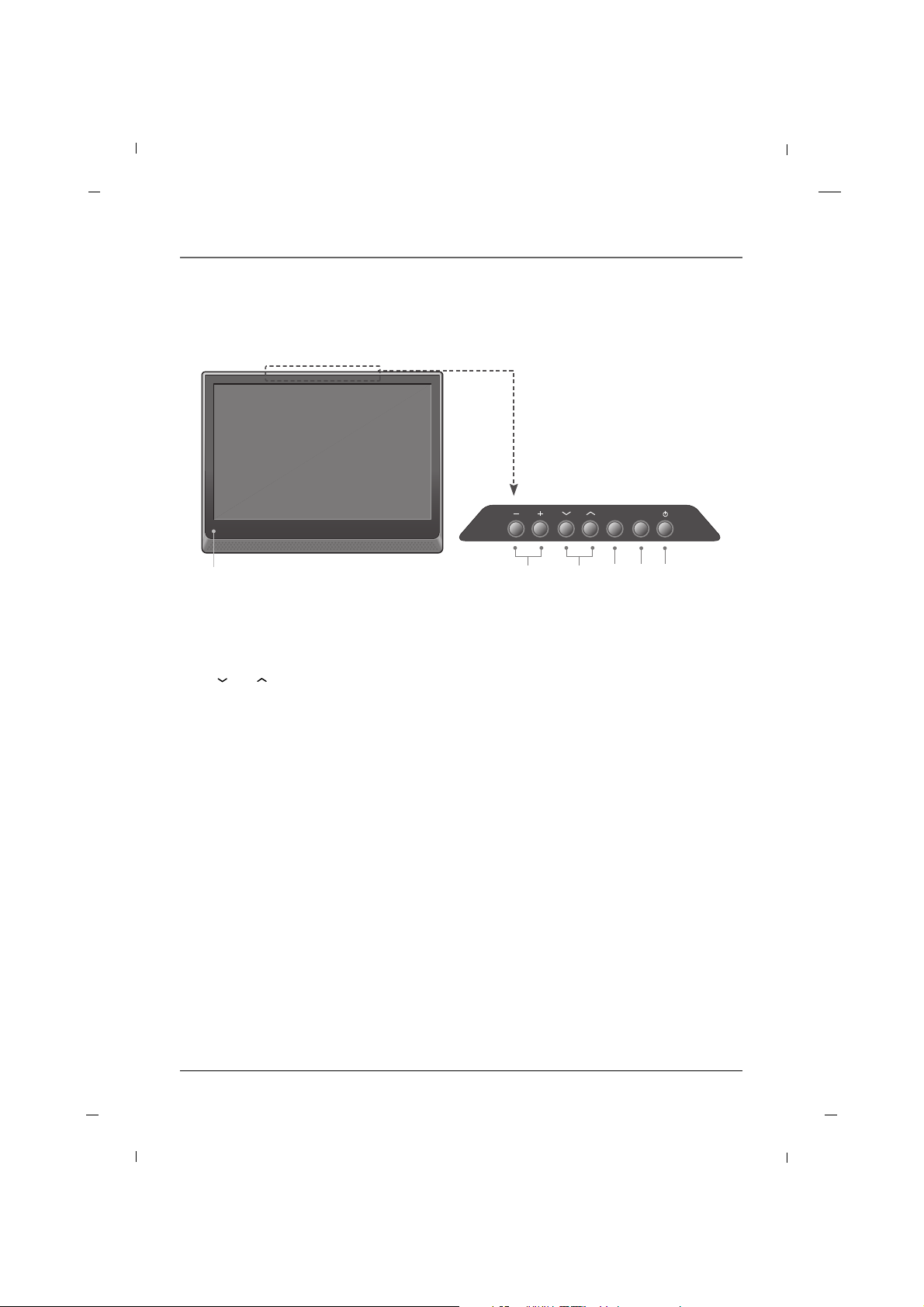
Chapitre 1: Branchements et installation
Chapitre 18
Panneau Avant - J22H760
1. VOL- / VOL+
Permet d’ajuster le niveau sonore et les ré glages du menu.
2. CH / CH
Sélectionner un poste.
3. SOURCE
Choisir le mode TV, AV1, AV2, YPbPr, VGA, HDMI ou USB.
4. MENU
Afficher le panneau de commande à l'écran.
5. POWER
Allumer ou éteindre le téléviseur.
6. Témoin lumineux
Bleu lumineux lorsque le téléviseur est allumé. Cette diode est également éteinte lorsque le téléviseur est
mis hors tension.
Capteur de la télécommande
Recevoir le signal infrarouge de la télécommande.
6
1 2 3 4 5
VOL
SOURCE
MENU
CH
Nota
- Image non contractuelle.
 Loading...