

RCA J32430YX50CJ5, J25420YX1AJ, J32430YX1CJ, J32430YX3CJ2, J32530YX52CJ9 Owner's Manual
...
RCA
COMMERCIAL TV
FOREWORD SAFETY INFORMATION
This publication will explain commercial TV, highlighting
accessories associated with the commercial TV. This manual is
designed to provide a basic understanding of commercial TV,
Clone PRO _M programming, and how third party systems control
the commercial TV.
For model specific information, please refer to the users manual or
the service data.
Note: This publication is to be used only as a training aid. it is not
meant to replace service data or the users manual. The Use and
Care manual, and Electronic Service Information, contain specific
information about parts, safety, alignment procedures and Use and
Care. The information in this manual is as accurate as possible at
the time of publication. Circuit designs and drawings are subject to
change without notice.
CAUTION
Safety information is contained in the appropriate Thomson Service
Data. All product safety requirements must be complied with. Anyone
who defeat safety features or tZailsto perform safety checks may be liable
for any resulting damages and may expose themselves and others to
possible injury.
Web Addresses:
www.service.tce.com (Authorized Service Centers Only)
or
www.thomsoncommercial.com
First Edition Commercial - First Printing
Copyright 2001 Thomson multimedia Inc.
Trademark(s)' Registered Marca(s) Registrada(s)
Printed in U.S.A.
Prepared by
Thomson multimedia Inc.
Technical Training Department
PO Box 1976
Indianapolis, Indiana 46206
U.S.A.
hen O

2

Contents
SAFETY INFORMATION .......................................................................................................................... 1
Commercial TV lntro ................................................................................................................................... 5
Jack Panel ..................................................................................................................................................... 7
Remote Controls (Master & Basic) ........................................................................................................... 11
Basic Menu .................................................................................................................................................. 13
Master Menu ............................................................................................................................................... 15
External Control of the TV ........................................................................................................................ 31
MCR Module Connections ......................................................................................................................... 33
Clone PRO TM (CBX-203) ............................................................................................................................ 35
Clone PRO TM Operation ............................................................................................................................. 39
Troubleshooting Hints and Tips ................................................................................................................. 41
Additional Information .............................................................................................................................. 45
Glossary ....................................................................................................................................................... 47
Index ............................................................................................................................................................. 51
IHtOA

Notes
4
Commercial TV lntro
Commercial TV's differ from non-commercial TV's in many areas. One
in particular is external control of the TV from third-party interactive
systems. Today, most commercial applications incorporate a third-party
control system, Master Antenna Television System (MATV), and some
sort of interactivity.
Commercial TV's:
have to be adaptable to the different types of third-party
systems in use today.
have two setup menus, a basic menu and a master menu.
(The master menu allows more control of set operation and
limits access to features commonly found on the basic menu
of non-commercial TV' s.)
have an interface for a third-party controlling device.
incorporate spill-resistant cabinets, (all grills, seams or other
openingsare designed to minimize the likelihood of cleaning
agents or spills entering the instrument and causing
operational problems).
incorporate integral mounting provisions, (mounting bosses
on the bottom of the cabinet that allow affixing the instrument
to existing mounts, brackets, and plates).
have restricted access to channels and menus, front panel
lockout, IR and wired cloning, and de-commercialization
features. (De-commercialization prepares the commercial TV
for after marked resale.)
RCA commercial TV's are indicated by the letter J at the beginning
of the model number and GE commercial TV's are indicated by the
letters GH in the model number. An example ofa RCA commercial
model number is J32430.
Commercial TV Application
Professional / Educational TV's arc mainly used in situations that
require televisions to always perform a particular function such as
always turn on with the volume preset and on the same channel. Certain
features and functions are enabled or disabled depending on the appli-
cation, in this application controlling of the TV externally, although
possible, is not common.
Lodging TV's are similar to Professional / Educational in that some
features are disabled and in some cases none of the TV's controls are
enabled, in a Lodging environment, the TV's are typically controlled by
an external device or set-top box connected to the Digital Serial
Communications lntert:ace (DSCI) jack. When connected to the DSCI
other devices can communicate with the TV sending it commands and
getting front panel or remote commands back from the TV. With this
interactivity, the user can send requests to the controller and do more
than the non-commercial TV. For example: Pay-Per-View and room
service can be requested by the customer using the on screen menu
system. The service can then be billed directly to the room account. This
type of interactivity can even include an itemized list of room charges
and advance checkout for the customer.
Healthcaresetsrequireadditionalfeaturesnottypicallyassociatedwith
Pro/EDorLodging.Healthcaresetsrequireclear,3-prong,6-footpower
cord.TheyarealsousedwiththePatientRemotePendant(PRP)that
usesastandardstereoV4 plug for controlling the TV. The pendant is a
wired remote control used to control basic functions of the TV. There
are two types of pendants; 1) Smart pendant and 2) "Dumb" pendant.
Smart pendants control TV on/off; volume, and channel +/- much like the
standard remote control does. The "dumb" pendant has channel up and
on/off capabilities only. Both smart and dumb pendants can incorporate
volume control of an external speaker and are hardwired to the TV.
Notes
6
Jack Panel
The jack panel is based on a particular application. Although
specific applications require specific jack panel connections, any
of the commercial TV's can be used in a commercial establishment.
The first commercial TV's only had the Pendant connection. As
commercial sets evolved, more interaction between user and the
TV became apparent. The DSCI was added to provide this type of
interactivity. Commercial TV's today have a pendant and or DSCI
port for external control of _he TV.
Note: The DS(T port and Patient Remote Pendant are not used at
the same time, Only one controlling device can be connected to
the TV at a time.
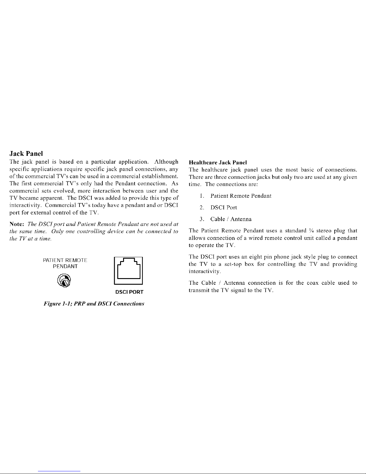
PATIENT REMOTE
PENDANT
@
Chl
DSCI PORT
Healthcare Jack Panel
The healthcare jack panel uses the most basic of connections.
There are three connection jacks but only two are used at any given
time. The connections are:
1. Patient Remote Pendant
2. DSCI Port
3. Cable / Antenna
The Patient Remote Pendant uses a standard V4 stereo plug that
allows connection of a wired remote control unit called a pendant
to operate the TV.
The DSCI port uses an eight pin phone jack style plug to connect
the TV to a set-top box for controlling the TV and providing
interactivity.
The Cable / Antenna connection is for the coax cable used to
transmit the TV signal to the TV.
Figure l-l; PRP and DSCl Connections

AX AX
DSCl PORT
CABLE/
AN[ENNA
Figure 1-2; Healthcare Jack Panel (DSCI and Pendant Plug)
Professional / Educational / Lodging Jack Panel
Figures L-3 and L-4 can be found in profcssionaL, educational, orlodging
applications. These applications typically do not use the Patient Remote
Pendant jack. Both jack panels have the DSCL for controlling the TV by
an external system. The other connections are features that are used in
different applications.
The DSCL only jack panel has basic connections and is used in
applications that require DSCL, cable / antenna, and possible video
and audio input. It can also be used with a stereo system.
The connections are:
Video: Composite video input from a VCR, DVD,
camcorder, etc. connected to the TV.
Audio R/L/Mono: Audio signal from a VCR, DVD,
camcorder, etc. connected to the TV to provide audio
input when using composite video.
R/L Out: Audio signal out to a stereo system amplifier
used when higher volumes levels are required.
Cable / Antenna connection is for the coax cable used to
transmit the TV signal to the TV.
DSCI port uses an eight pin phone jack style plug to
connect the TV to a set-top box for controlling the TV and
providing interactivity.
VIDEO AU[IIO
R L/MONO _--_
@@@,.
R L
@@oo, /k
DSCI PORT
CABLE]
ANTENNA
Figm'e 1-3; DSCI only
8
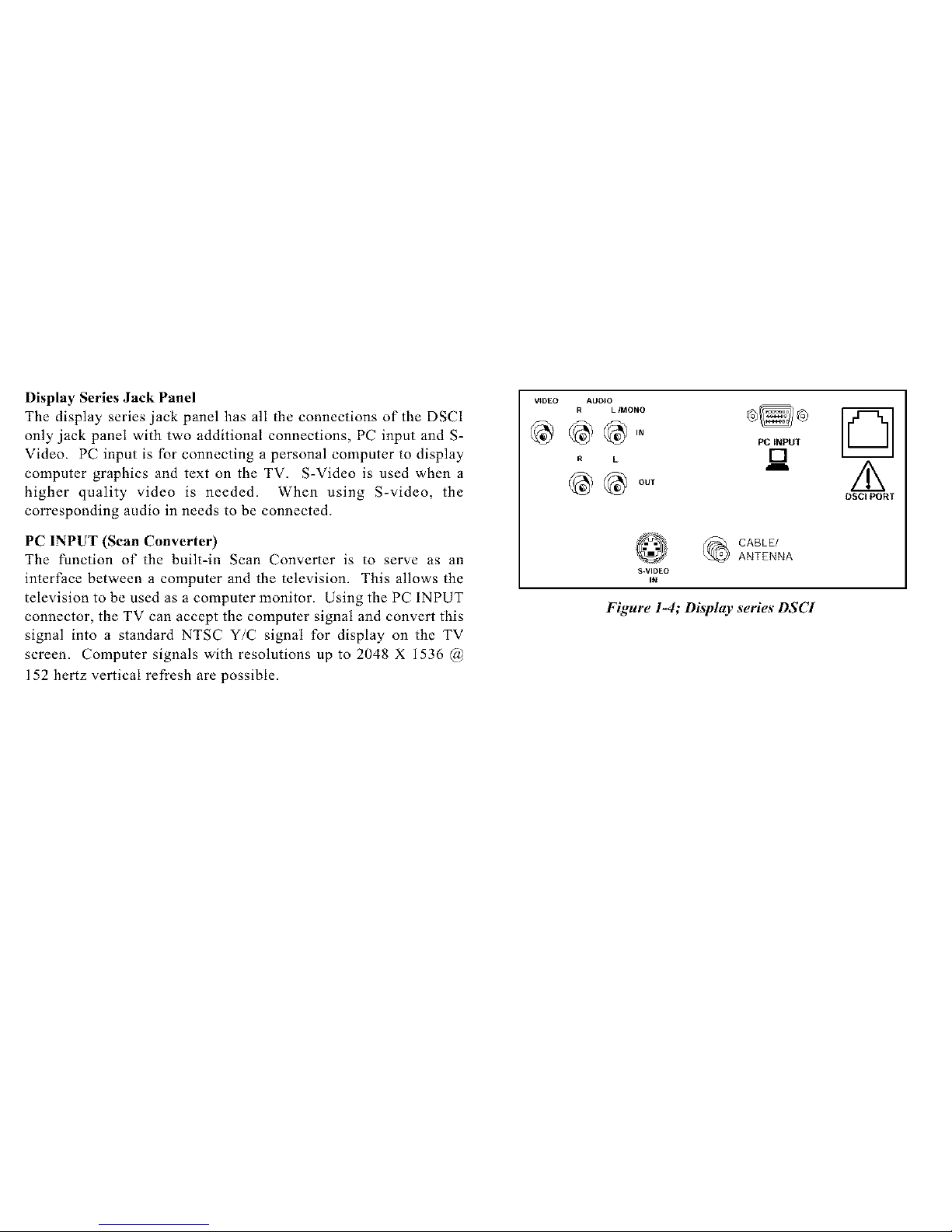
Display Series Jack Panel
The display series jack panel has all the connections of the DSCI
only jack panel with two additional connections, PC input and S-
Video. PC input is for connecting a personal computer to display
computer graphics and text on the TV. S-Video is used when a
higher quality video is needed. When using S-video, the
corresponding audio in needs to be connected.
PC INPUT (Scan Converte O
The function of the built-in Scan Converter is to serve as an
interface between a computer and the television. This allows the
television to be used as a computer monitor. Using the PC INPUT
connector, the TV can accept the computer signal and convert this
signal into a standard NTSC Y/C signal for display on the TV
screen. Computer signals with resolutions up to 2048 X 1536 @
152 hertz vertical refresh are possible.
V_DEO AUDIO
R L IMONO
R L
S.VIDEO
IN
PCtNPUT
[]
CABLE/
ANTENNA
Figure 1-4; Display series DSCI
D
/k
DSCl PORT

Notes
10
RemoteControls (Master & Basic)
A Master remote is different from a Basic remote in menu access only.
Master remotes have special coding to access the hidden or master menus
of the TV. Basic remotes can only access the basic menus that are
allowed by setup of the master menu. To setup a commercial TV
functions, the master remote or Clone PRO __jclone box needs to be used.
No other remotes can access the master menus. When using the basic
remote to make changes in the menu, each time the set is turned off. the
changes will return to the detZault settings when powered on. Changes
made by using the master remote will remain when power is removed
from the TV. These settings can only be changed back by using a master
remote or the Clone PRO TM. Aside from the special coding used to
access the master menu, the master remote is the same as the basic
remote.
appear to control the TV via 1R but are doing so through the DSCI input
on the back of the TV. These remotes are typically used where pay-per-
view systems are in place and require a set-top box for control. These
remotes do not have the coding to control the TV directly, but control the
set-top box instead. The set-top box then controls the TV via the DSCI
jack. Therefore, when the TV is not responding to remote commands,
check the set using the Clone PRO _Mclone box connected to the DSCI
port. if the TV responds to the Clone PRO _j, there is nothing wrong with
the TV. (Functions of the Clone PRO _Mmay be limited by the setup of
the TV and type of control the set-top box has. At a nfinimum, power on/
off should work.)
A Thomson universal remote is capable of many other operations that a
basic remote is not, for instance; programmable to other brands of VCR,
Cable/Sat, and audio systems. Like the basic remote, the universal can
access the basic menu but is not capable of getting into the master menu.
Universal remotes have the ability to control two Thomson TV's that are
in the same vicinity but independant of each other. TV 1and TV2 buttons
allow controlling two sets using one remote. See Master Menu section,
on page 15, for TVI and TV2 setup.
NOTE:
There are other remote hand units specific to some set-top boxes that
V ¸
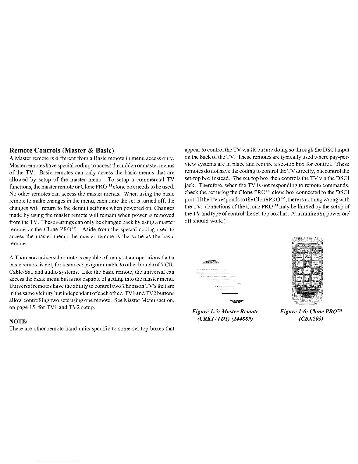
Figure 1-5; Master Remote
(CRK I 7TD I) (244889)
Figure 1-6; Clone PRO TM
(CBX203)

Notes
Figure l-7; Basic Users Figure l-8; Universal Remote
Remote (Basic)
(CRKI7TCI) (244888) (CRK76TKI) (247437)
Note: Numbers in () are stock mtmbers _br ordering remote,
12

Basic Menu
The basic menus are accessed using the basic remote or the front
panel Menu button. The menus that are available, depend on the
restrictions set by the master user and the active input. For instance,
if Basic Menu Access has been set to Disabled in the Access and
Power Options menu, the basic menus will not be available.
Many of the changes made in the basic menu will revert to their
master menu settings the next time the TV is turned on. Most all
the basic menu items function the same as their master counter
parts. Refer to the users manual for more detailed operation of the
menu items that are different.
NOTE: Some.features, such as PC Video Input Controls, are not
available unless that input has been selected prior to entering the
menu. This holds true/or both Basic and Master Menus,
Figure 2-1; Main Menu (Basic)
Notes

Notes
14
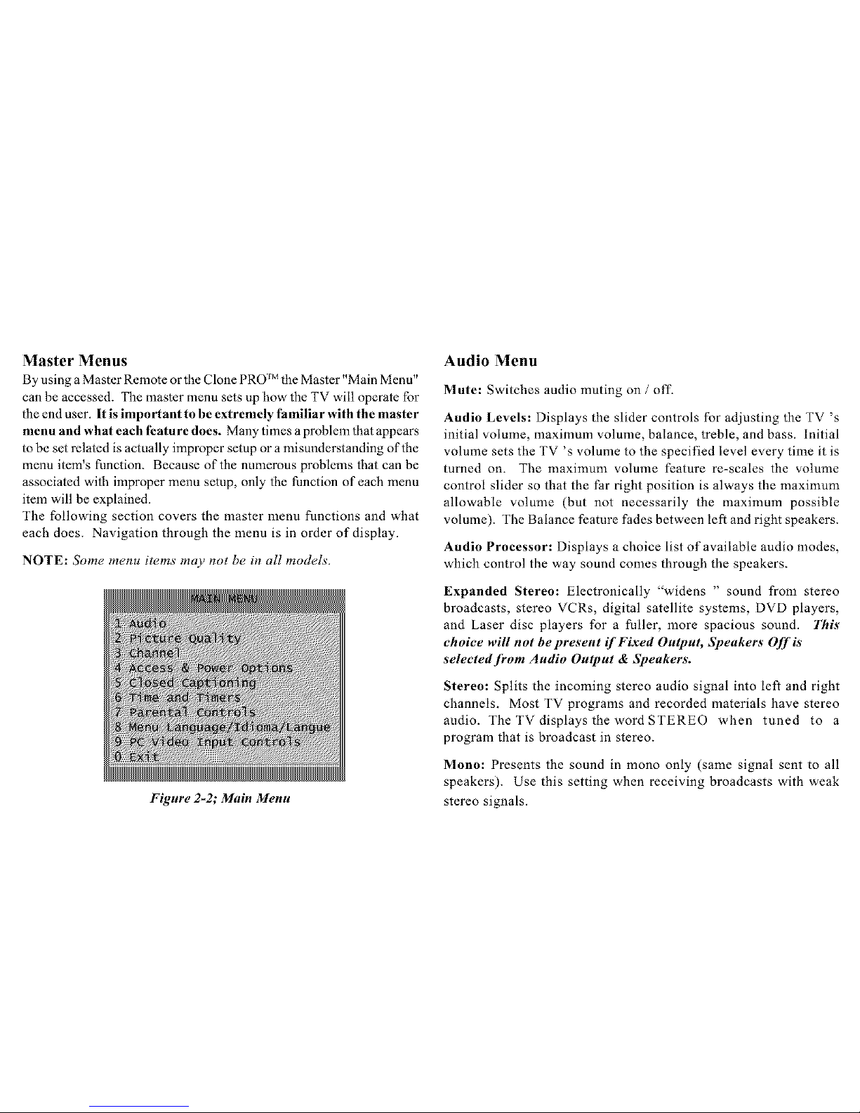
Master Menus
By using a Master Remote or the Clone PRO ]Mthe Master "Main Menu"
can be accessed. The master menu sets up how the TV will operate for
the end user. It is important to be extremely familiar with the master
menu and what each feature does. Many times a problem that appears
to be set related is actually improper setup or a misunderstanding of the
menu item's function. Because of the numerous problems that can be
associated with improper menu setup, only the function of each menu
item will be explained.
The following section covers the master menu functions and what
each does. Navigation through the menu is in order of display.
NOTE: Some menu items may not be in all models.
Figure 2-2; Main Menu
Audio Menu
Mute: Switches audio muting on / off-
Audio Levels: Displays the slider controls for adjusting the TV's
initial volume, maximum volume, balance, treble, and bass. Initial
volume sets the TV's volume to the specified level every time it is
turned on. The maximum volume feature re-scales the volume
control slider so that the Par right position is always the maximum
allowable volume (but not necessarily the maximum possible
volume). The Balance feature fades between left and right speakers.
Audio Processor: Displays a choice list of available audio modes,
which control the way sound comes through the speakers.
Expanded Stereo: Electronically "widens " sound from stereo
broadcasts, stereo VCRs, digital satellite systems, DVD players,
and Laser disc players for a fuller, more spacious sound. This
choice will not be present if Fixed Output, Speakers Off is
selectedJkom Audio Output & Speakers.
Stereo: Splits the incoming stereo audio signal into left and right
channels. Most TV programs and recorded materials have stereo
audio. The TV displays the word STEREO when tuned to a
program that is broadcast in stereo.
Mono: Presents the sound in mono only (same signal sent to all
speakers). Use this setting when receiving broadcasts with weak
stereo signals.
SecondAudioProgram(SAP):Presentstheprogram'saudioina
secondlanguage,if oneisavailable.TheTVdisplaystheword
SAPwhenyoutuneto a programthatis broadcast with SAP
information. SAP audio is broadcast in mono. SAP is also used
to broadcast a program's audio with descriptions of the video for
the visually impaired.
Audio Output & Speakers: Displays a choice list that let's you
turn the TV's internal speakers on or off and set the audio outputs
to fixed-level or variable control level.
Variable Output, Speakers On: This setting turns the TV's
speakers on and sets the variable output from the TV's audio output
jacks, proportional to the volume setting.
Variable Output, Speakers Off: This setting turns the TV's
speakers off and allows variable output from the TV's audio output
jacks.
Fixed Output, Speakers Off: This setting turns the TV's speakers
off and allows fixed output from the TV's audio output jacks to an
external device such as a surround sound amplifier. When this
[euture is turned on, the TV's volume control, tone controls,
Expanded Stereo, and mute are disabled.
Volume Hold: This setting tarns the TV's speakers on and sets the
audio outputs proportional to the current volume setting. When
this 3"euture is turned on, mute and other volume controls are
disabled.
16
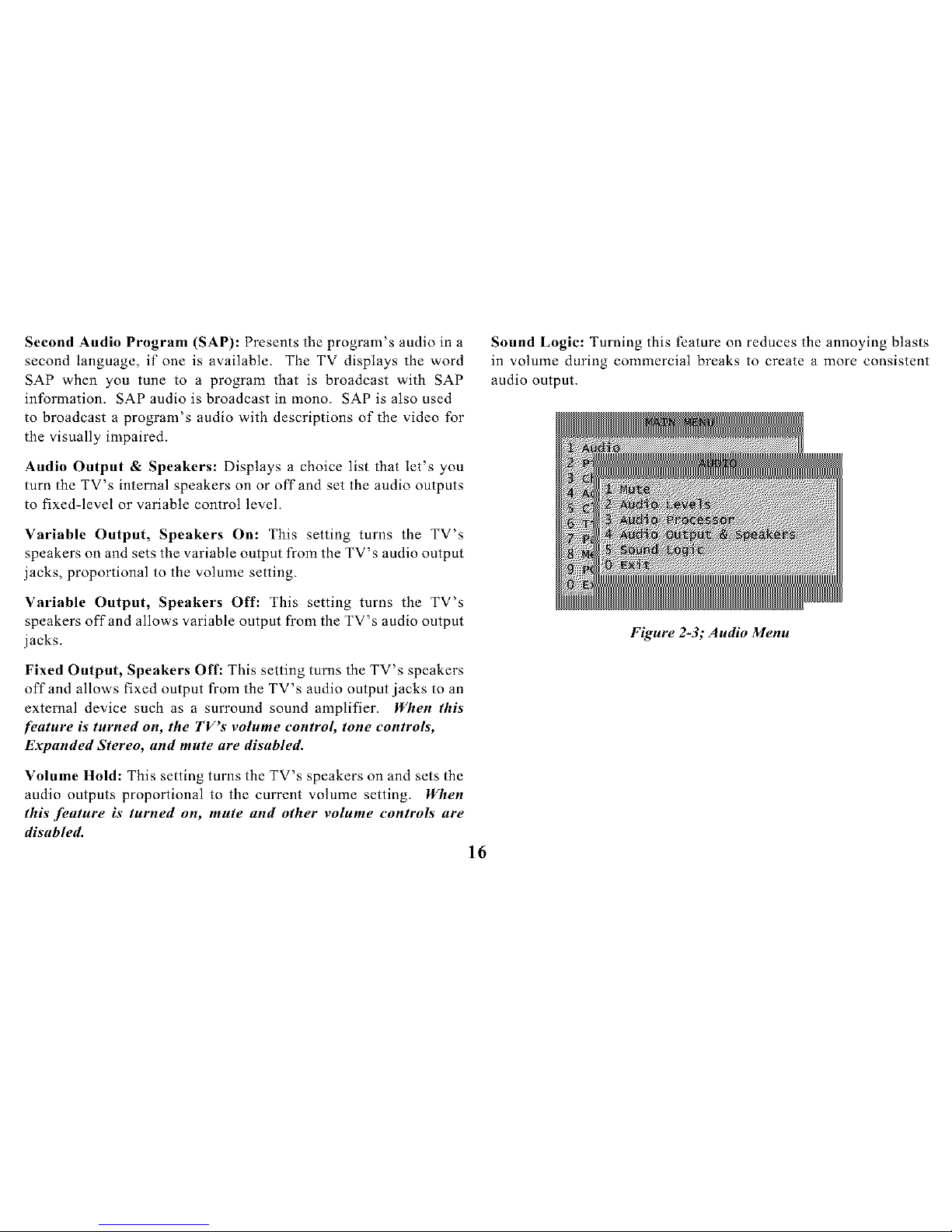
Sound Logic: Turning this feature on reduces the annoying blasts
in volume during commercial breaks to create a more consistent
audio output.
Figure 2-3; Audio Menu

Picture Quality Menu
The Picture Quality menu items allows appearance adjustment of
the on-screen images. Pressing RESET on the remote control
returns all Picture Quality menu settings to their factory defaults.
Picture Adjustments displays the five-slider controls for adjusting
the way the picture looks in the current video input source. (These
settings can be set differently fbr each video input source.)
Contrast: Adjusts the difference between the light and dark
areas of the picture.
Color: Adjusts the richness of the color.
Tint: Adjusts the balance between the red and green levels.
Black Level: Adjusts the brightness of the picture.
Sharpness: Adjusts the crispness of edges in the picture.
When exiting the Picture Adjustments menu, the Save Custom
Picture Preset choice list appears. Sore the settings as a Custom
Picture Preset that way the setting can be returned !f someone
changes the settings.
Picture Presets: DispLays a choice list of four preset picture settings:
Bright Lighting, Normal Lighting, Soft Lighting, or Custom Picture.
Bright Lighting is the default and will be selected if the RESET
or SKIP button is pressed while in this menu.
Auto Color: Displays a choice list to turn on or off the feature that
automatically corrects the color of the picture. (This is especially
useful for tracking realistic flesh tone colors when switching from
channel to channel.)
Color Warmth: Displays a list of three automatic color adjustments:
Cool for a more blue palette of picture colors; Normal and Warm
for a more red palette of picture colors. The warm setting
corresffonds to the NTSC standard of 6500 K.
Picture Tilt: Screen sizes 32" and up have extra-large picture
tubes, which make them vulnerable to the effects of the Earth's
magnetic field. Picture Tilt compensates for this effcct.
Figure 2-4; Picture Quality Menu

Channel Menu labels.
Channel Guide: Displays the list of channels and their labels (if
labeled) in the cu_xently selected channel list.
Channel Selection: Allows the master user to set the initial channel
and to select which of the three channel lists will be accessible to
the basic user_ If no initial channel is selected, the TV will select
the last tuned channel when turned on. If Hold is selected, the user
will not be able to select any channel other than the initial channel.
Signal Source: Displays a choice list that allows selection of the
current signal source and turn muting and blanking on or off for
weak signals.
UHF/VHF: Choose this if currently using an oft-air antenna for
TV signals.
Cable TV: Choose this if currently using cable or a cable box for
TV signals.
Auto Channel Search: Tells the TV to search automatically for all
the channels available through the antenna input. When the TV
finds an active channel, it places it in the selected channel list;
inactive channels (weak stations or channels with no signal at all)
will be removed from that channel list.
Note: Pressing RESET or SKIP in the Lists and Labels" menu
returns the highlighted field to its default status.
Channel: Use the up and down arrows to scroll up and down through the
channels available.
Lists A, B, and C: Use the up and down arrows to indicate what
channel number is to be included in the highlighted channel list.
Channels included in a list will be available to users when that list
is active. Channels not included in the active list will not be
accessible to users.
Channel Label: Use the up and down arrows to enter a label of up
to eight characters for each channel. Hold the button down to
scroll quickly through the characters. Press RESET or SKIP to
clear the currently highlighted label. Toprevent a channel number
/?om di._playing on the screen, select "#" as the eighth labe!
character,
List and Labels: Displays a control panel that allows editing of the
three channel lists and an eight-character label for each channel.
Follow the on-screen directions to customize channel lists and
18
Figure 2-5; Picture Quality Menu

Auto Tuning: Displays a choice list that allows setup of the TV to
automatically tune to the correct input channel when pressing the
component button (VCRI, DVD, VCR2, or SAT) on a universal
remote.
The component button choices are:
VCR1 : Displays a choice list that lets you select the channel
that the TV tunes to when you press the VCRI button.
VCR2: Displays a choice list that lets you select the channel
that the TV tunes to when you press the VCR2 button.
DVD: Displays a choice list that lets you select the channel
that the TV tunes to when you press the DVD button.
AUX: Displays a choice list that lets you select the channel
that the TV tunes to when you press the AUX button.
SAT: Displays a choice list that lets you select the channel
that the TV tunes to when you press the SAT (or SAT
•CABLE) button.
The input channel choices are: (not all choices are available on
all models)
Ch 3: Choose this if the component is connected to the
antenna jack on the back of the TV, and want the TV to
tune to channel 3 when the specified component button is
pressed. Make sure the component's Ch 3/4 switch is set to
Ch 4: Choose this if the component is connected to the
antenna jack on the back of the TV, and want the TV to
tune to channel 4 when the specified component button is
pressed. Make sure the component's Ch 3/4 switch is set
to channel 4.
VID: Choose this if the component is connected to the
Audio and Video In jacks on the back of the TV and want
the TV to tune to the VID input channel when the specified
component button is pressed.
SVID: Choose this if the component is connected to the S-
VIDEO jack on the back of the TV and want the TV to
tune to the SVID input channel when the specified
component button is pressed.
S-VHS or Super-VHS: This is an extended format of
VHS and improves the picture quality of the signal passing
through the S-VIDEO input. Make sure to also connect
audio cables in order to get sound when using S-Video.

PC: Choose this if the component is connected to the PC
INPUT jack on the back of the TV and want the TV to tune
to the PC input channel when the specified component
button is pressed. Figure 2-6; Channel Menu
Figure 2-6; Channel Menu
Access & Power Options
This control panel allows the master user to specify which features
and functions basic users will be able to access. Yellow and green
color-coding shows each item's status:
Yellow: default setting.
Green: change Dom default setting or un-set password.
Remote Configuration: This feature tells the TV under what
circumstances to respond to remote control commands.
TV1 or TV2: TV will respond if the remote is in either mode.
TV2: TV will only respond to a remote in TV2 mode.
Disabled: TV will not respond to a remote at all, except MENU
from the master remote. Once TV1 or TV2 status has been assigned
to the TVs, the remote will have to he setup as well.
On a master renlote_
1. Point the remote at the TV1 TV.
2. Simultaneously press and hold the SYSTEM and 1 buttons.
3. After three seconds, release the buttons. The TVI TV
should now respond to the remote.
4. To control a TV2 TV, simply repeat the process using the
2 button and a TV2 TV.
On a universal remote:
1. Point the remote at the TV1 TV.
2. Press the TVI button to put the remote in TV1 mode.
3. To control a TV2 TV, simply repeat the process using the
TV2 button and a TV2 TV.
TVI: TV will only respond to a remote in TVI mode.
2O

Basic Menu Access: This feature tells the TV to either enable or
disable the basic menu. When the basic menu is disabled, users
cannot access menus through the basic remote or the front panel.
TV Power Configuration: This feature determines whether the
TV can be turned on and off with the POWER button on the remote
or the front panel.
Switched: The TV can be turned on or off; the Energy Saver can be
enabled.
Remote: The TV cannot be turned on or off with the front panel.
Always: The TV cannot be turned on or off. all Energy Saver
settings will be ignored.
Energy Saver Setting: When enabled, this feature will turn the TV
off after a specified period of inactivity (no remote or front panel
button presses). When disabled, the TV will not turn off"
automatically, lf TV Power Cow,figuration is set to Always, Energy
Saver Settings will he ignored.
Figure 2-7; Access & Power Options Menu
Closed Captioned Menu
Many programs are encoded with closed caption information, which
displays the audio portion of a program as text on the TV screen.
Closed caption is not available on all channels at all times, it only
appears on specific programs encoded with closed caption
information. When a program is closed captioned the letters "CC "'
are displayed in the Status Display.
Closed-Caption Display
The Closed-Caption Display and PIP Closed-Caption Display select
which one will have Closed Caption displayed. In the PIP Closed-
Caption Display, selecting the Alternate with PIP button choice
results in the following sequence when the PIP button is pressed:
PIP without closed caption
PIP with closed caption
No PIP
Closed-Caption Modes
There are eight closed-captioned modes, including four text modes.
To set the Closed-Caption Mode for the main screen or PIP window:
1. Select Closed Caption from the Main menu.
2. Highlight Closed-Caption Mode or PIP Closed-Caption

3_
Point to your choice and press OK to select it and return to
the Closed Caption menu.
Schedule: Sets up a schedule for turning the TV on and off
automatically. Follow the on-screen directions through the steps
needed to set the schedule.
Note: Pressing the RESET or SKIP button while in the Schedule
control panel clears both the start and stop times and selects
lnactive in the Schedule Status field.
Figure 2-8; Closed Caption Menu
Time and Timers Menu
Current Time: Enters the current time. Follow the on-screen
directions through the steps needed to set the time. This feature is
accessible by basic users only if Time Cor_figuration is set to Basic
(unless an invalid time is received).
Sleep Timer: Selects the amount of time the TV is on before it
shuts itself off. One minute before the scheduled shut off, a
warning will appear on the screen indicating the Sleep Timer's
status. When this message is present, any remote or front panel
button press will turn the Sleep Timer off'. The Sleep Timer can
also be accessed directly using the SLEEP button on the remote.
Time Configuration: This control panel allows control of several
time-related functions.
Schedule Recurrence: Selects the type of scheduling function the
user will have:
Disabled: Prevents the basic user from viewing or changing
the Schedule menu item.
Recurring: This schedule will he in effect indefinitely;
both the master and basic user can view and change the
Schedule menu item.
One4ime: This schedule will only be active once unless
reset. Both the master and basic user can view and change
the schedule menu item.
22

Set Time Access: Selects who is able to change the current time:
Disabled: Prevents the basic user from viewing or changing
the current time menu item unless an invalid time is
received. The basic user will still be able to view the
current time in the Status Display ifa time has been set.
Automatic: The time is automatically set by using a time-
set channel. Basic users can view the current time menu
item, but cannot change it.
Basic: Both the master and basic user can view and change
the current time menu item.
Daylight Savings: When on, tells the TV to automatically adjust
for daylight savings time.
Time Offset: Set an offset time (from+12 to -12 hours) from the
UTC (Universal Time, Coordinated).
Parental Controls Menu
The Parental Controls menu allows programming of the TV so that
children cannot see certain programs, channels, or use the front
panel controls.
The choices in the Parental Controls menu involve software inside
the TV (dubbed V-Chip), which allows blocking of TV programs
and movies containing violence, sex, or other content not intended
for children. Programs can be unblocked by entering a password.
Note the default state is off and basic users have no access to
Parental Controls. When turned "on,'" the software reads a code
that most broadcasters send with programs. That code tells the
software the program's age-based rating (TV-MA, TV-14, etc.)
and content themes (Violence (V), Adult Language (L), etc.). If
the rating or content themes that the program contains are blocked,
the message "This channel is not approved for viewing" will be
displayed. Broadcasters are not required to provide content themes,
so programs received with no content themes will only be blocked
if their age-based rating is blocked. Movies that have been given a
rating of"Not Rated," and programs that are considered "un-rated
"because no code has been sent by the broadcaster, can be blocked.
Figure 2-9; Time And Timers Menu

Locked/Unlocked
Selecting this option allows lock and unlock of parental control
settings using a password. Follow the on-screen instructions to
lock or unlock blocked programming (the default password is
5625). If parental controls are not locked, none of the settings for
V-Chip, Channel Block, or Front Panel Block will take effect.
Master users can enter a new password at any time through the
Password menu option.
V-Chip Movie Rating Limit
Movie rating limits are set by blocking movies rated above a
specified level. To access the V-Chip Movie Rating Limit menu:
1. Press MENU on the remote control (the TV Main menu
appears).
2. Select Parental Controls.
3. Select V-Chip Movie Rating Limit.
Blocking Movie Ratings
To allow viewing of movies that have a PG rating and lower (in other
words, movies rated PG and G), and automatically block all movies
with higher ratings, do the following:
1. Highlight the Rating field, and press the up and down
arrows to find the rating that is the lowest rating you do not
want the child to watch.
24
2_
3_
4.
Use the right arrow to highlight the Rating Status field.
Press the up and down arrows to change the button from
View to Block. All higher ratings ' View buttons will
automatically change to Block.
Press OK to return to the menu or exit the screen.
Parental Controls must be locked so the movie rating
limits will take effect.
Viewing Movie Ratings
After movie ratings are blocked, there is the option of changing
some of the Rating Status fields back to View.
1. Highlight _he Rating field, and press the up and down
arrows to find the rating to view.
2. Use the right arrow to highlight the Rating Status field.
Press the up and down arrows to change _he button from
Block (red) to View (green).
3. Press MENU or OK to exit the screen, and be sure parental
controls are locked.

V-Chip TV Rating Limit
The V-Chip TV Rating Limit lets the user decide what TV programs
can and cannot be viewed.
To set TV programming limits:
Choose Parental Controls from the Main menu. If Parental
Controls have previously been locked, the correct password
must be entered. If they are not locked, a message that the
limits will not be effective until you lock Parental Controls
is displayed.
2. Press MENUto continue.
3. Highlight and select V-Chip TV Rating Limit.
4. Once on the V-Chip TV Rating Limit screen, use the
arrows and OK on the remote to change the status ofa TV
program rating or content theme from View to Block.
Blocking Age-Based Ratings
This will automatically block all program ratings above a specified
age-based rating level. For example, if wanting to view a TV-G
rating and lower program (in other words, to only watch TV-G, TV-
YT, and TV-Y), then all programming with higher ratings need to be
blocked.
To block programs with higher ratings:
1. First, determine the highest level rating allowed for viewing.
2_
3.
4_
5.
6_
7.
Use the left and right arrows to highlight the Rating field.
Use the up and down arrows on the remote to scroll through
the age-based rating limits. Keep scrolling until the rating
corresponding with the highest viewable rating appears.
In the example discussed above, scroll through the choices
in the Rating field until TV-PG appears, since the highest
rating is TV-G.
Use the right arrow to move the yellow highlight to the
Rating Status field.
Press the up or down arrow to toggle between View and
Block. The status for the rating listed to the left and all
higher ratings automatically changes to Block (B, red).
Press MENU or OK on the remote to return to the menu or
exit the screen.
Select Lock Parental Controls from the Parental Controls
menu. Enter a password, and if you have not already set
your password, you will be prompted to enter it again to
confirm.

Viewing Age-Based Ratings
Once the age-based ratings are blocked, there is the option of
changing some of the ratings back to View.
1. Determine which blocked rating you want to view.
2. Use the left and right arrows to highlight the Rating field.
3. Use the up and down arrows to select the rating whose
status is Block.
4_
5.
Press the right arrow to move the yellow highlight to the
rating status field.
Press the up or down arrows to toggle between View and
Block.
Blocking Specific Content Themes
This will block programs based on their content. (Content is
represented by the D L S V and FVon the screen. When blocking a
content theme for a particular rating, the content theme for higher
rated programs is automatically blocked. For example, if blocking
programs that have adult language (L) rated TV-PG or higher, then
block TV-PG.
To block program content:
1. Determine the highest level of content to be viewed.
2_
3.
4_
5.
Use the left and right arrows to highlight the Rating field.
Use the up and down arrows on the remote to scroll through
the age-based ratings until the rating that corresponds with
the highest content to be viewed appears.
Press the right arrow to move the highlight to the field
corresponding with the content theme to block out.
Press the up or down arrow to change content status from
V to B. All higher ratings ' content theme will automatically
change to B.
6. Press MENU or OK to return to the menu or exit the
screen.
Viewing Specific Content Themes
Once the specific Content Themes are blocked, there is the option
of going back and changing some of the Content Themes back to
View (V):
1. Determine the content themes to change to View (V).
2. Use the left and right arrows to highlight the Rating field.
3. Use the up and down arrows to scroll through the age-
based ratings until the rating whose content theme to change
appears.
26

4_
Press the right arrow to move the yellow highlight to a
particular content theme status, such as the B under
language (L) corresponding with TV-14.
5. Press the up or down arrows to change its status back to V.
This allows programs with TV-14 adult language content
to be viewed, but not programs with TV-PG or TV-MA
language content.
V-Chip Un-rated Program Block
Selecting this option determines if programs that the V-Chip recog-
nizes as "un-rated "can be viewed. Note tbat "un-rated "' TV
programs may include news, sports, political, religious, local and
weather programs, emergency bulletins, and public announcements.
Also, the first few seconds of a rated program may be blocked due to
a brief delay in tbe transmission of the rating.
View: All un-rated programs are available.
Block: No un-rated programs are available.
Channel Block
Selecting this option determines what channels can be viewed.
View: Makes the selected channel viewable.
Block: The front panel and remote control CH A/V (channel up and
down) buttons will tune only to channels that are marked as View.
The remote will still tune to the blocked channel if using the digits
to access the channel, but the audio will be muted and the video
will he renlaced with the Channel Block Warning, Disr_lav.
This channel has not been
approved for viewing.
Change channel or
_ress SELECT/OK to enter password
and temporarily deactivate
Parental Controls.
Password
Selecting this option sets up a Parental Controls password (the
default password is 5625 "lock " on a telephone-style keypad).
Master users can enter a new password without being prompted for
the old one. Basic users must enter the old password before they
can create a new one.
Figure 2-10; Parental Controls Menu

MenuLanguage
The Menu Language selection affects only the menus. It does not
change the audio language. The menu language choices are:
English Spanish or French.
Figure 2-1l; Menu Language Menu
PC Video Input Controls
This menu item will appear if the TV PC input is selected. There are
four ways of selecting the PC input:
1. Selecting the PC input from the active channel list using
the CH +/-buttons.
2_
3_
Pressing the WHO ,INPUT button, until PC INPUT is
selected.
4. Selecting channel 128.
Make sure the TV is connected to a PC or similar device before
selecting PC Video input Controls.
Zooming:
To enlarge or reduce the on-screen image by zooming.
The OK button toggles the zoom options:
lx displays the image at full size
2x displays the image at twice its full size
Panning:
When "zoomed in " to 2x, the viewable image will be larger than
can be shown on the screen at one time. Panning with the Arrow
buttons allows the user to view diffcrent portions of these enlarged
images. Pan up to view portions of the image currently above the
screen, pan left to view portions of the image currently to the left of
the screen, and so on.
Freezing and Unfreezing:
This functions like a "Pause " button with a VCR. The word
FREEZE will be displayed on the screen until this function is
deactivated.
Auto tuning with the remote. (See Auto Tuning on page
13.)
28

UsingVideoSettings
Video settings are changed by pressing the FORWARD (FF) or
REVERSE (REW) buttons, which simply take you through the
presets in different orders. The Video Presets are:
2.
3.
4.
Text &Graphics (Default) Choose this if your PC input
image contains both text and graphics.
Text on Bright Bkgrd Choose this if your PC input image
contains dark text on a light background.
Text on Dark Bkgrd Choose this if your PC input image
contains light text on a dark background.
Graphics Optimized Choose this if your PC input image
contains mainly graphics or if graphics are more important
than text.
Resetting
Pressing RESET simply resets zooming, panning, freezing and video
settings to their detZaults.
Figure 2-12; PC Video Input Controls Menu
A feature of _he master menu is when the setup is complete the
settings are stored until changed later. Even in the event of power
failure, the changes are still there. When using the basic remote to
make changes in the menu, each time the set is turned off those
changes will be lost and return to the default settings when powered
back on.

Notes
30

External Control of the TV
In most applications the commercial TV is controlled by a third-
party device hard wired to the set. This is accomplished in on...._eof
two ways.
1. Digital Serial Communication lntert:ace (DSCI)
2. Patient Remote Pendant plug (PRP)
The DSCI provides more control of the TV then the Pendant. The DSCI
uses serial communication, IR communication and is capable of two-way
communication. It also provides + 12Vdc power for third-party use. The
PRP is used primarily in Healthcare applications.
Interactive Systems (Set-Top Boxes)
There are several different interactive systems available today.
The most common ones are: On Command Video and Lodgenet.
Most use a set-top box to provide interaetivity. When connected to
the DSCI, the set-top box can provide pay-per-view movies, media-
retrieval and control, patient and staff education, guest services,
and other automated control of the TV. The fundamental equipment
required for an interactive system includes; in-room hardware (set-
top box), head-end (MATV), and communication system. The set-
top box is hardwired to the TV's DSCI jack. See MCR Module
Connections on page 27 for a pin out of the DSCI.
[Set-top Box I
/-
._[Control Center]
Figure 3-l; Set-top Box Block Diagram
Pleadend
Distribution
Center

Patient Remote Pendant (PRP)
There are two types of wired Patient Remote Pendants, "dumb" and
"smart". A "dumb" pendant is nothing more than a switch closure
between two contacts. On healthcare TV's this contact closure
tells the set to channel up once for each key press, in the event the
set is powered off; the first key press will turn on the set and each
preceding key press changes the channel. Once the last channel has
been reached, the next key press will turn off the set. There is no
other interaction between user and TV with a dumb pendant.
Using a smart pendant provides the user with more control of basic
functions like volume up and down, channel up and down, and on/
off2 The smart pendant uses data pulses similar to a remote control.
Both smart and dumb use a standard stereo V4" plug to connect to
the TV for communication and can have audio out to a pendant
speaker. Some pendants have mechanical volume controls to adjust
audio level of the pendant speaker. See MCR Module Connections
on page 28 for a pin out of the PRP.
Pendant
Hand unit
FloorCeiling, or]
Wire connecting
Pendant to TV.
Figure 3-2; Pendant Block Diagram
32

MCR Module Connections
The commercial TV uses an MCR (remote-control module) for third-
party connection and control. The MCR module has one and/or two
control jacks on it.
1. Digital Serial Communication lnterIZace (DSCI)
2. Patient Remote Pendant plug (PRP)
The type of commercial installation determines what MCR module
or connections are available. All MCR modules have the DSCI,
but only the healthcare has a PRP. The DSCI has serial
communication, infrared (IR) remote output, and is capable of two-
way data transfer for complete monitoring and control of the
television. It also provides +12Vdc power for third-party devices.
The PRP, used with Healthcare applications, has limited
interactivity.
Function DSCI Pin #
Without serial data:
1
(hannel list slection
asyschronous serial data
2
out
asynchronous serial data 3
m
12V dc power out 4
resmwed 5
Ground 6
detected IR sigllal output 7
auxiliary output (External
hardware control ie. A/V 8
switching)
Figure 4-l; DSCI Pin Identification

_? iringl sleeve
Function PRP Pin #
Audio Signal Tip
Control Signal Ring
Ground Sleeve
Figure 4-2; Pendant Plug Pin Identification
Notes
34

Clone PRO TM (CBX-203)
The Clone PRO ]M clone box is a self contained, baltery operated,
microprocessor controlled device used to facilitate the programming
process for commercial TV. Because the commercial TV has a
wide range of features and options, programming of multiple sets
can be time consuming. In most commercial applications there
maybe several to hundreds of sets that all need to be setup the same
way; this is where the Clone PRO _j helps. With a learn / teach
feature, the Clone PRO _Mcan program several sets in less time than
someone going into each sets menu and setting them up manually.
By programming one set and using the Clone PRO _Mto learn the
TV's setup, the other televisions in the establishment can then be
programmed using the teach function of the Clone PRO _j.
Additionally, the Clone PRO _Mcan be utilized as a tool to:
1. Clear the television's memory.
2. Prevent unauthorized and unsupervised programming.
3. Allow or disallow front panel programming.
4. Commercialize or de-commercialize a set.
5. Set legacy bit. (For OnCommand operation)
6. Troubleshoot the MCR board communication.
There are two ways the Clone PRO _Mcan accomplish programming
a set. 1) Digital Serial Communications Interface (DSCI)
"SmartPlug", and 2) Wireless remote operation. When using DSCI
("SmartPlug"), the Clone PRO _Mis physically connected to the TV
via a standard (1 to 1, non-flipped) 8-conductor computer-network
cable. When using IR the Clone PRO _Mneeds to be pointed (line
of sight) at lhe IR receiver of the TV.
Figure 5-1; Clone PRO TM
(CBX203)

Switches and Indicators
The Clone PRO _Muses a number of switches and indicators to
select, initiate, and verify the process.
DSCI mode: (Green Color)
"ready LED"
Indicates the Clone PRO _M is properly connected to the
TV via DSCI port and is ready for commands.
"busy LED"
Indicates data transfer to and/or from the Clone PROPEL
"Comm."
Commercializes a de-commercialized TV.
"Legacy"
Sets legacy bit for OnCommand operation.
"Decom."
De-commercializes TV for after market resale of
commercial TV
"[Status]"
Pressing and holding this button for a few seconds brings
up a display showing the settings stored in the Clone
PRO _j and the TV.
"RESET, INFO, OK, MENU, CLEAR, and Arrow
Buttons"
These buttons perform their expected function as if they
were on a nlaster renlote.
"LEARN"
This begins the process of learning the settings from a
television that has been configured as desired for the
particular application.
"POWER"
Toggles the TV on and off in the DSCI mode.
"TEACH"
This begins the process of teaching the setting stored in
the Clone PRO _Mto the television to which it is connected.
"[Factory]"
Pressing and holding this button for a few seconds resets IR mode: (Red Color)
the TV to Factory defaults. (This will not Commercialize a "ready LED"
De-commercialized set) Indicates the Clone PRO _Mis powered on and in the IR
mode.
36

"busy LED"
Indicates data transfer from the Clone PRO _Mvia IR.
"Master +" and "Master -"
These enable and disable, respectively, access to the TV's
master menus for configuration.
"Config"
Allows or disallows front panel programming.
"RESET, INFO, OK, MENU, CLEAR, and Arrow
Buttons"
These buttons perform their expected function as if they
were on a master renlote.
"ON"
Turns on the Clone PRO _Mand puts it in the IR mode.
"OFF"
Turns off the TV.
"TEACH"
This begins the process of teaching the setting stored in
the CLone PRO _Mto the television.
Figure 5-2; Clone PRO TM

Notes
38

Clone PRO TM Operation
Receiver to Clone PRO r_l (LEARN)
Once a television has been programmed, connect the DSCI cable
from the Clone PRO _Mto the television (.lack on back of TV). With
the television on or off; push the Learn switch. The "busy" LED
will mm on during the programming cycle and turn off when
finished, ffthe television is on, an on-screen display will indicated
the process as well. This completes the CBX-203 learning process.
Clone PRO _1 to Receiver (TEACH)
In the Teach mode, the Clone PRO IMhas two ways of transmitting
the data to program the television. IR is the easiest and requires no
physical connection between the Clone PRO _Mand the TV.
Wired Clone PRO TM to Receiver (TEACH)
With AC power applied and the television turned on or off; connect
the Clone PRO _Mto the television's interface connector (DSCI
Port) with an appropriate connecting cable. Push the Teach switch.
The busy LED should light indicating the program cycle has started.
When finished the busy LED will turn off indicating the program
cycle is complete. If the television is on, an on-screen display will
indicated the process as well.
Wireless Clone PRO TM to Receiver (TEACH)
Hold the Clone PRO _Mapproximately two to three feet in fi'ont of
the television. Point the Clone PRO _Mat the IR window on the
front of the TV and push the ON switch. Press the Teach switch
and the busy LED should light indicating the program cycle has
started. When finished the busy LED will turn off indicating the
program cycle is complete. An on-screen display will indicated the
process as well.
Clone PRO TM Hints
When using the Clone PRO _Min the IR mode, the Clone
PRO _j will time out after about 30 sec. if no keys are
pressed.
When connected to the television, via the DSCI jack, the
Clone PRO _Mgets it's power from the TV. There is no
need for the battery when using the DSCI connection.
If the Clone PRO IMis in the IR mode (IR ready LED is lit)
and the DSCI is then used to connect to the TV, the Clone
PRO TM will not function until the IR mode times out.
NOTE: The 1R read), LED wi!I go out and the green DSC7
ready LED will be lit, but art), key press on the Clone
PRO _/ and the 1R LED bray will light indicating the
Clone PRO 7_tis still in the 1R mode.
If the Clone PRO _Mlocks up and no functions seem to be
working, the DSCI cable and the battery need to be
disconnected for 3-5 minutes to reset the Clone PRO _M.

NeverdisconnecttheDSCIcablewhiletheClonePRO_M
isintheprocessofLearningorTeaching.
Alwaysclonea workingsetfirstthenre-clonetheset
suspectedofhavingprogrammingerrors.(LearnandTeach
functionontheClonePROI_j)
WhenusingtheDSCIoption,theTVcanbeturnedonof
off- if theTVison,thereison-screendisplayinformation
indicatingtheprocessbeingpreformed.
WhenusingtheIR(TEACH)function,theTVneedstobe
turnedon.
DSCI Jack
Figure 5-4; Clone PRO TM
DSCI and IR End View
Figure 5-3; Clone PRO TM
40

Troubleshooting Hints and Tips
As with any troubleshooting a logical thought process is required to
accomplish the task. The first thing when dealing with commercial TV
is to check setup menu for proper setup. A short cut metbod to determine
if the set has a setup problem is to take a working TV set and learn using
tbe Clone PRO _M.Then using the Clone PRO TM, teach the set in question.
This procedure will insure the two sets are setup the same.
The Clone PRO ]Mis a useful tool in troubleshooting the commercial TV.
With a complete understanding of how the Clone PRO TM works, one can
determine if the TV or the system it is hooked to is the problem. Using
the DSCI communication port as the test point, hook up the Clone PRO ]M
using tbe cable supplied and check for proper communication by either
teaching or learning tbe set. The green busy and ready LED's indicate
data communication. Turning on the set and channel change are another
indication that the DSCI is working.
Patient Remote Pendant can be tested by taking a known working
pendant and connecting it directly to the back of the TV. if the set works,
check the wiring from the pendant to the TV. The PRP is a simple three-
wire connection but if wired wrong it will not work.
TV will not turn on
Check to make sure it is plugged in.
Check the wall receptacle (or extension cord) to make sure
it is "live " by plugging in something else.
Check batteries in remote control.
Insure remote control is aimed at the remote sensor on the
TV.
TV power or remote configurations may be preventing
this. Use a master remote control to change menu settings.
TV turns on or off unexpectedly
The Scheduled Off or Scheduled On function may have
been activated in the Time and Timers menu.
The Sleep Timer or Energy Saver function may have turned
the TV off. Check menu setting under Sleep Timer and
Energy Saver. Note: Sleep timer can be re-set by
unplugging the TV, wait 5 minutes and plug it back in.
No picture or bad reception
Try another channel.
Check antenna connections.
If watching video from an external component, make sure
the component is connected to the input jacks and the
component is turned on.
Press RESET, in case the picture controls are set too low.
(If brightness and contrast are set to _heir minimum, the

If usingaVCR(connectedonlythroughantennainput),
makesureTVistunedtochannel3or4 thesameas
CH3/4switchonVCR.
If usingaVCR,checktomakesuretheTV/VCRbuttonon
theVCRisinthecorrect"mode."
WeakSignalMutingandBlankingmaybeon(fromthe
Mainmenu,selectChannelMenu,thenSignalSource)
Tryadjustingsharpnesstoimproveweaksignals(fromthe
Main menu,selectPicture Quality then Picture
Adjustments.
Black box appears on the screen
Closed Captioning may be turned on and in text mode.
Check the Closed-Caption Display control panel by
pressing CC on the remote control or through the Main
nlenu.
No sound, picture okay
Be sure sound is not muted. Try pressing the VOL A (up)
button to restore sound.
Make sure speakers are turned on. Check, the Audio
Output and Speakers control panel in the Audio menu.
If using an S-VHS connection, remember to also connect
the component's L and R AUDIO OUT jacks to the TV's
L and R INPUT jacks.
Check Maximum Volume seting in the Audio Levels control
panel in the Audio menu.
Noisy stereo reception
Weak station or poor reception. SelectMono in the Audio
Processor control panel of the Audio menu.
42

Problems with remote
Operation of certain remote control buttons might be
restricted by master menu settings.
Make sure nothing is between the remote and the remote
sensor that could block the signal.
Point the remote directly at the device you are trying to
control.
If using a remote with component buttons, make sure
remote is in the TV mode. Press the TV button so remote
will control the TV. See also the input signal problems
description later in this section.
Wrong configuration (TV1 or TV2) for that TV. Check
the Remote Configurations setting in the Access and Power
Options menu. See the "Master Menus " section for more
details.
Check batteries in remote, dead or installed incorrectly.
Try replacing batteries. (if using a programmable remote
and the batteries are remove, the remote will have to
reprogramed to control other components.)
Remove batteries and hold the 1 button for at least 60
seconds to drain the microprocessor inside the remote.
Release the 1button, replace the batteries, and (if necessary)
reprogram the remote.
Can't select certain channel
Channel may be blocked or not approved in tbe Parental
Controls" menu.
Channels" not in the current channel Hst cannot be
accessed except through the master Channel menu.
If using a VCR, check to make sure the TV/VCR button on
the VCR is in the correct "mode."
Input signal problems
Make sure that the input channel choice in the Auto Tuning
menu matches the component's physical connection. For
example, if you have set VCR] to CH4 in Auto Tuning, but
the VCR is connected by Audio/Video cables or an S-
Video cable, you will see normal channel 4 programming
when the VCRI button is pressed. See the Auto Tuning
description under Channel Menu in the "Master Menus "
section for further instruction.
Menu problems
Menu access may be blocked by clone boxprogramming.
The Energy Saver settings win not work if TV Power
Config. is set to Always in the Access and Power Options
inenn.
The basic menu options might be restricted by master

Forgot
Rating
PC Video input Controls only appear in the Main menu if
the PC input is selected. See the PC input Video Controls
entry in the "Main Menus " section for more information.
The clone box may have disabled master menus.
Sleep and Schedule .fimctions won't work if TV Power
Config is set to Always.
password
Use the master remote to enter a new password.
limits don't work
You must lock the parental controls (from the Main menu,
select Parental Controls then Lock Parental Controls.
Program is blocked and it shouldn't be
It may be a Not Rated (NR) movie. After you block movie
ratings, you must set NR to View separately in order to
view movies with an NR rating (from the Main menu,
select Parental Controls then V-Chip Movie Rating Limit.
It may be an un-rated television program. To unblock un-
rated television programs, select Parental Controls from
the Main menu, then select V-Chip TVRating Limit and set
un-rated to V.
Notes
44

Additional Information
www.service.tce.com (Authorized Service Centers Onl) )
or
www.thomsoneommercial.com.
Notes

Notes
46

This glossary is intended to familiarize the reader with common
terminology and provide a reference for other industry terms.
A-to-D Converter (ADC)
An electronic component used to convert analog signals to
digital.
Aliasing
Undesirable video display effect caused by excessive high
frequency information. The results are "jaggies" or a stairstepping
effect of slanted lines and fonts.
Alignment
The process of adjusting an electronic circuit to obtain maximum
performance.
Amplification
The process by which the strength of a signal is increased.
Amplifier
An electronic device used to increase the strength of a signal.
Analog
A system in which signals vary continuously in contrast to a
digital system in which signals vary in discrete steps.
Anti-aliasing
The process of reducing the aliasing effect. Usually involves
placing a gradual gradient from the slanted line color to the
background color to "smooth" the jaggies.
Aspect Ratio
The ratio of television screen width to height. The standard
aspect ratio is 4 to 3. in computer jargon, television screen size
is 768 x 576 pixels including overscan, although actual viewing
screen resolution is normally considered to be 720 x 484. High
Definition broadcasts will normally be closer to a 16 X 9 format.
ATSC
The U.S. Advanced Television System Committee.
Audio
The sound portion of the television signal.
A/V Cables
Audio/Video Cables carry the baseband audio and video output
signals demodulated from the RF channel received by the tuner.
Baseband Video
The composite NTSC standard signal that contains all the color
and black/white information needed to produce normal video on
a television screen. The baseband signal originates at the
production Facility or studio and later modulated, or mixed, onto
a channel carrier for transmission over broadcast, cable, MATV
or SMATV systems. The receiver or television must then strip
off the channel carrier, leaving the original composite signal.
CAV (Component Analog Video)
Analog video format in which three separate video signals
(RGB), are combined to represent luminance (Y) and color (C)
information.

Chipper Check TM
Computer interthce and software that allows alignment and
reinitalization of the television via personal computer.
Chrominance (Chroma or "C")
The hue and saturation of a color. The chrominance signal is
modulated onto a 4.43 MHz carrier in the PAL television system
and a 3.58 MHz carrier in the NTSC television system.
Clone Box
A device used to program several commercial TV's by cloning.
Interlaced Scanning
A scanning technique to minimize picture flicker while conserving
channel bandwidth. Even and odd numbered lines are scanned in
separate fields that, when combined, paint one frame of complete
picture. The effect is the picture is divided into two separate
pictures, the odd lines and even lines. Both must be recombined
to present a proper picture. See Progressive Scanning.
Luminance (Y)
The measurable, luminous intensity of a video signal. Color
video picture information contains two components: luminance
(brighmess & contrast and chrominance (hue & saturation).
MATV
Master Antana Television
MCR
(Remote-control module) mounted inside the television, used as
an interface between the TV and an external controling device.
48
Micro, microprocessor, uP, microcontroller
The system control device of a television receiver.
Monochrome
A black and white television picture.
NTSC
The National Television Standards Committee which created the
standard for North American TV broadcasts.
PAL
Phase Alternate Line. The European color TV format which
evolved from the American NTSC standard.
Pendant
A wired remote control used in controlling commercial TV's.
There are two kinds of pendants, SMART and DUMB.
PDP
Plasma Display Panel
Phosphor
Material that emits light when excited by radiant emergy.
Pixel
"Picture element" or "pel." A pixel is a digital sample of the
color intensity values of a picture at a single point.
Plasma display
A display that uses ionized gas to produce light.

ProgressiveScan
Methodofpicturescanningwithonehorizontallineimmediately
followingtheonebefore.SeeInterlaced.
PRP
PatientRemotePendant
PWB
Printed Wire Board
RGB
Red, Green, Blue. The primary additive colors used to reproduce
the color signal in color television.
RS-170A (ANSI/SMPTE 170M)
Composite Analog Video standard detailing the matrixing of
RGB video signals onto one of two color difference signals: Y,
B-Y, R-Y or Y, 1Q.
Scan Converter
A device used to convert scan signal from one format to another.
SDTV (Standard Definition Television)
Term used to signify a digital television system (DTV) in which
the quality is approximately equivalent to that of analog NTSC.
This equivalent quality may be achieved from pictures sourced
at the 4:2:2 level oflTU-R Recommendation 601 and subjected
to processing as part of the bit rate compression. The results
should be such that when judged across a representative sample
of program material, subjective equivalence with NTSC is
achieved. Also called standard digital television. See
SECAM (Systeme Electronique Pour Colour Avec
Memorie)
French developed broadcast standard.
Signal Conversion
The process of taking a signal at one frequency or a specific
ca_Tier frequency and changing it to another.
SMATV
Satelite Master Antenna Television
S-Video
Split or Separated Video. Video output technique separating the
color from the black & white information to improve picture
quality.
SVGA
Super Video Graphics Adapter
Terrestrial
Originating from the earth, as in terrestrial broadcast. This
would refer to a normal over-the-air broadcast signal as opposed
to a satellite-based signal.
UTC
Universal Time, Corrdinated (zulu or Greenwich Mean Time,
GMT)
VGA
Video Graphics Adapter

Y/C
Commonly referred to as "separate video" or "S-Video". A
video signal containing a separate Y (luminance) and C
(chrominance) signal. The Chroma signal is normally modulated
at 3.58 MHz. in video tape recording it may be at 688 MHz (3/
4" & Beta) or 627 MHz (VHS).
YIQ
NTSC video signal standard for normal transmission. The
original RGB signals are combined this way. Y=luminance, the
black and white component with sync produced by combining
30% Red + 59% + 11% Green. i60% Red - 28% Green - 32%
Blue, Q=21% Red - 52% Green + 31% Blue. The I&Q signals
are modulated onto a 3.58MHz subca_Tier for transmission. The
receiver nmst then demodulate the subcalTier back into the
original i & Q signals necessary to decode the original RGB
levels. (See also RS-170)
YUV
Luma and Chroma difference components normally recognized
as a PAL video signal standard where Y=Luminance, U=Red-Y,
V=Blue-Y. These signals can be recombined to form RGB
video. Generally cleaner than other methods requiring some
frequency conversion of the separate color and luminance signals.
Y, CI, C2
A general set of CAV signals. Y is the luma signal, C 1is the first
color difference signal and C2 is the second.
Y, Cb, Cr
Digital expression of the color difference signals. Cr is the
digital interpretation of R-Y, while Cb is the digital interpretation
of B-Y.
Y, Pb, Pr
Analog expression of the color difference signals. Pr is the
equivalent to R-Y, while Pb is equivalent to B-Y.
Y, R-Y, B-Y
The general set of CAV signals used for some encoder/decoder
systems in PAL and NTSC systems. Specifically, Y is luminance,
R-Y is the first color difference signal and B-Y is the second.
Y,Pb,Pr is a version of this system. (See also RS-170)
5O

Index
A
Audio 8
Audio Levels 15
Audio Processor 15
Auto Channel Search 18
Auto Color 17
Auto Tuning 19
B
Basic Menu Access 21
Basic menus 13
Basic remote 11
Black Level 17
C
Cable / Antenna 8
Cable TV 18
Channel 18
Channel Block 27
Channel Guide 18
Channel Label 18
Clone PRO _M 35
Closed Captioned 21
Closed-Caption Modes 21
Color 17
Color Warmth 17
Contrast 17
CmTent Time 22
D
Daylight Savings 23
De-commercialization 5
Digital Serial Communications InterFace 5
DSCI 5
DSCI port 8
Dumb pendant 6
E
Expanded Stereo 15
H
Healthcare 6
I
Integral mounting 5

Interactive Systems 31
a
Jack panel 7
L
ListsA, B, and C 18
Lodging TV 5
M
Master Antenna Television System 5
Master menu 5
Master Menus 15
Master remote 11
MATV 5
MCR 33
MCR Module 33
Mono 15
Movie Rating Limit 24
Mute 15
P
Panning 28
Parental Controls 23
Password 27
52
Patient Remote Pendant 6, 32
PC 28
PC INPUT 9
Pendant 6
Picture Presets 17
Picture Tilt 17
Professional / Educational TV 5
PRP 6, 32
R
Remote Configuration 20
Resetting 29
SAP 16
Scan Converter 9
Schedule 22
Schedule Recurrence 22
SecondAudio Program 16
Set Time Access 23
Set-top box 5
Set-Top Boxes 31
Sharpness 17
Signal Source 18
Sleep Timer 22
Smart pendant 6

SoundLogic16
Stereo15
Switched21
T
Time Configuration 22
Time Offset 23
Tint 17
TV Power Configuration 21
U
UHF/VHF 18
Universal remote 11
V
V-Chip 24
V-Chip Movie Rating 24
Video 8
Volume Hold 16
Z
Zooming 28

FirstEdition-FirstPrinting
Copyright2001ThomsonmultimediaInc.
Trademark(s)[_RegisteredMarca(s)Registrada(s)
PrintedinU.S.A.
T-COMM203- I
PRINTED ON RECYCLED PAPER
CONTAINING MINIMUM OF FiVE
PERCENT POST-CONSUMER WASTE
 Loading...