

Page 1

J1000/J1100 Wireless Speaker
Installation Guide
NOTE: Once properly installed the TV speakers will no longer
produce sound. All sound from the TV will now come through the
wireless speaker. There is no change to the TV operation. The TV
remote control will still operate the volume of the speaker (make sure
remote is pointed at the TV, not the speaker).
Mounting Instructions (continued)
Install Transmitter
Step 1–Attach transmitter to top of TV by applying supplied double stick tape to the
“lip” of the transmitter and securing to the top front face of the TV.
Step 2–Plug AC adapter into the transmitter and wall outlet.
Step 3–Select “channel” on back of transmitter to match the channel” of the speaker.
Step 4–Use supplied RCA cable to connect transmitter input to Variable Audio Output
from the TV or use supplied headphone cable to connect from headphone jack of TV.
Step 5–Adjust Volume Limiter to “MIN” position.
Set-up
Step 1–After completing step 5 above, use TV remote and adjust volume on TV to MAX.
Step 2–Incrementally adjust the Volume Limiter on the transmitter from MIN towards
MAX until desired maximum volume is reached for the wireless speaker.
Troubleshooting
• Volume of speaker too low. 1) raise volume on TV, 2) increase volume limiter on the
back of transmitter
• Speaker sounds distorted. 1) The volume limiter on the transmitter is too high, 2)
Lower volume of TV
• No sound comes from speaker. 1) Ensure no cables are plugged into optional port on
back of speaker.
• Sound MUTES occasionally. 1) Raise transmitter and/or speaker height, 2) slightly
angle transmitter up to allow signal to reflect off ceiling.
Page 2
Product Overview
This Wireless speaker system is designed to transmit audio from TV to a
speaker across the room resulting in a more comfortable listening level. This
system includes a transmitter (to be placed above the TV) and a speaker (to be
placed above the bed)
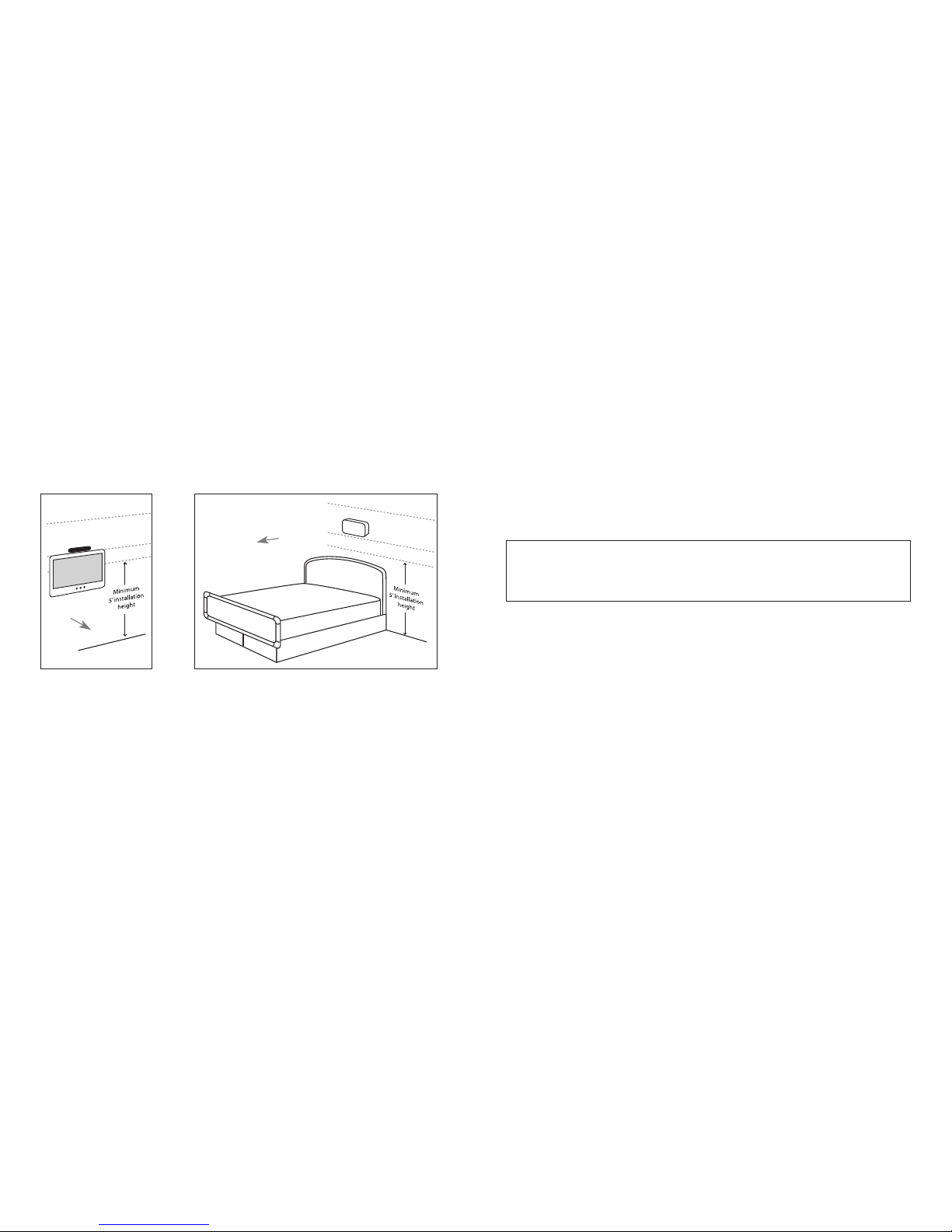
IMPORTANT--This speaker system works by IR and requires direct line of
sight from the transmitter to the speaker. To work properly, there cannot be
any obstructions between the transmitter and speaker.
The transmitter must be mounted a minimum of 5 feet above the floor with 6-7
feet being optimal. The speaker must be mounted above the bed and at least 5
feet above the floor with 6-7 feet being optimal.
WARNING--This product is placed above the bed and must be properly in-
stalled. Failure to install properly could result in serious injury. This product
and included hardware were designed to be installed on drywall. If you are
mounting to another type of wall, please contact RCA Commercial for specific
guidance.
Mounting Instructions
Install Wall Bracket and Speaker
Step 1-- Install Wall Bracket to wall above bed (at least 5 feet up from the
floor) using supplied snap toggle hardware on the left and right “keyholes”
(see below). The 3 middle holes can be used for ADDITIONAL stability but
require additional hardware that is not included.
Step 2-- After wall bracket is securely mounted, attach speaker to wall bracket
using supplied thumb screws. NOTE: Angle of speaker is adjustable..
Step 3-- Plug AC Adapter into speaker and wall outlet or insert lantern battery
behind speaker grille.
Step 4-- Select “channel” on back of speaker to match “channel” on transmitter.
NOTE: Each speaker and transmitter has 2 channel selections either
channel 1/2 or channel 3/4 depending on the model. You can use up to 4
wireless devices per room, but you cannot use the same channel more than
once per room.
Using the Snap Toggle hardware:
Drill a 1/2” hole. Hold metal channel flat alongside plastic straps and slide
channel through hole. Minimum clearance behind wall: 1-7/8”.
Hold ends of straps between thumb and forefinger and pull toward you until
channel rests flush behind wall. Slide plastic cap along straps with other hand
until flange of cap is flush with wall.
Snap straps at wall by pushing side to side, snapping off straps level with
flange of cap.
Place item over flange. Insert bolt through item and tighten until flush against
item, then stop.
Use machine screw or bolt to match thread in channel: BA (3/16”-24), BB
(1/4”-20), BM5 (M5), and BM6 (M6).
Bolt length = item thickness + wall or ceiling thickness + 1/2”
6’ - 7’
optimum
height
Receiver mounted
above TV on
opposite wall
6’ - 7’
optimum
height
6’ - 7’
optimum
height
Receiver mounted
above TV on
opposite wall
Receiver mounted
above TV on
opposite wall
Page 3

Installation Template on other side Installation Template on other side
Page 4

Installation Template
Place the template directly on the wall where the bracket will be mounted. Making sure that the template is
level and at optimum height (between 6 - 7 feet from the floor), mark each place to be drilled, making marks
at each crosshair to ensure accurate hardware placement.
(800) 709-8731
www.directvideotv.com
______
_
sales@directvideotv.com
 Loading...