

Page 1

IP Video Decoder
User’s Guide
Changing Entertainment. Again.
TOCOM 16195310
English/Français/Español
IP900
Page 2

Important Information
CAUTION
RISK OF ELECTRIC SHOCK.
DO NOT OPEN.
This symbol indicates "dangerous
voltage" inside the product that
presents a risk of electric shock or
personal injury.
Caution: To reduce the risk of electric shock, do not remove
cover (or back). No user serviceable parts inside. Refer
servicing to qualified service personnel.
This symbol indicates important
instructions accompanying the
product.
WARNING
To reduce the risk of fire or electric shock, do not expose this product to rain or
moisture.
IMPORTANT SAFETY INSTRUCTIONS
When using this product, basic safety precautions should always be followed to reduce the
risk of fire, electric shock, and injury to persons, including the following:
1. Do not use this product near water, for example, near a bathtub, wash bowl, kitchen sink
or laundry tub, in a wet basement, or near a swimming pool.
2. Use only the power supply indicated in this manual.
SAVE THESE INSTRUCTIONS
Refer to the identification/rating label located on the back panel of your product for its
proper operating voltage.
FCC Regulations state that unauthorized changes or modifications to this equipment may void
the user’s authority to operate it.
Caution: To reduce the risk of fire, use only No. 26 AWG or larger DSL telecommunication line
cord.
The apparatus should not be exposed to dripping or splashing. Also, no objects filled with
liquids, such as vases, should be placed on the apparatus.
Page 3

Table of Contents
Chapter 1: Connections and Setup
Things to Consider Before Connecting Components ............................... 3
Cables to Connect Components to Your IP Decoder................................ 3
Choose Your Connection............................................................................. 4
TV + IP Decoder + Modem ......................................................................... 5
TV + VCR + IP Decoder + Modem ............................................................. 7
TV + A/V Receiver + IP Decoder + Modem .............................................. 9
Turn on the TV and IP Decoder ................................................................ 10
Put Batteries in the Remote Control....................................................... 10
Put Batteries in the Optional Wireless Keyboard .................................. 10
Chapter 2: Remote Control
The Buttons on the Remote Control ....................................................... 11
Using the INPUT Button.................................................................................................. 13
Volume Punchthrough ..............................................................................13
Programming the Remote to Operate Other Components.................... 14
Find Out If You Need to Program the Remote ......................................................... 14
Programming the Remote .............................................................................................. 14
How to Use the Remote After You’ve Programmed It...........................15
Code List .................................................................................................... 16
Chapter 3: Decoder Features
Using the Remote Control to Choose On-screen Menu Items ............. 18
Using the On-Screen Keyboard ............................................................... 18
Shift, Alt, Ctrl Keys ...........................................................................................................18
Shortcut Keys ..................................................................................................................... 18
Using the Web Browser ............................................................................ 19
Browser Banner ................................................................................................................. 19
Browser Toolbar ................................................................................................................ 19
Entering a Website Address ........................................................................................... 19
Web Page Navigation ...................................................................................................... 20
More Features ........................................................................................... 20
Viewing Your Bookmarks ................................................................................................ 20
Selecting Bookmarks ....................................................................................................... 20
Saving Your Bookmarks................................................................................................... 21
Viewing Your History ....................................................................................................... 21
1
Page 4

Table of Contents
Chapter 4: Additional Information
Troubleshooting ......................................................................................... 22
Care and Cleaning ..................................................................................... 23
Service Information .................................................................................. 23
FCC and Industry Canada Information .................................................... 24
Front of the Decoder ................................................................................25
Back of the Decoder ................................................................................. 25
How to Find Your TV’s Video Input Channel .......................................... 26
Video Input Channel Variations .................................................................................... 26
2
Page 5

Chapter 1: Connections and Setup
Things to Consider Before Connecting Components
Protect Components From Power Surges
• Connect all components before plugging any power cords into the wall outlet.
• Always turn off the TV and other components before you connect or disconnect any cables.
Position Cables to Avoid Audio Hum or Interference
• Insert all cable plugs firmly into their jacks.
• Place any Audio/Video (A/V) cables to the side(s) of the TV’s back panel instead of straight down the
back after connecting components.
•Try not to coil any twin-lead antenna cables and keep them away from all A/V cables as much as
possible.
• Make sure all antennas and cables are properly grounded. Refer to the Safety Tips sheet packed with
your unit for detailed information.
Protect Components From Overheating
• Never block ventilation slots in any component. Arrange the components so that air can circulate
freely.
• Do not stack components.
• Allow adequate ventilation when placing components in a stand.
• Place an amplifier or other hot component on the top shelf of a stand so heated air rising from it
will not flow around other components.
Cables to Connect Components to Your IP Decoder
The pictures below show the cables that can be used for the connections represented in this book.
Audio/Video cables
(included)
Coaxial cable
Digital Optical cable
Ethernet cables
S-Video cable
(included)
Chapter 1 3
Page 6
Chapter 1: Connections and Setup
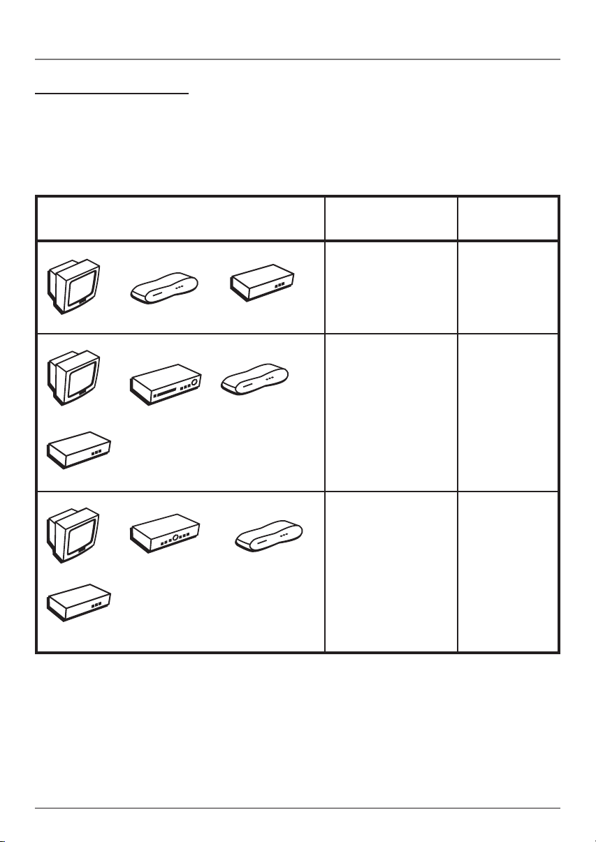
Choose Your Connection
There are several ways to hook up your IP decoder, depending on the components connected. Please use
the following chart to determine which connection is best for you and proceed to the appropriate page.
Note: For assistance in connecting your decoder, contact your service provider.
Components
TV
TV
Modem
TV
IP Decoder
VCR
A/V Receiver
Connection Title Go To
TV + IP Decoder page 5
+ Modem
Modem
TV + VCR + pages 6-7
IP Decoder +
Modem
IP Decoder
TV +A/V Receiver pages 8-9
+ IP Decoder +
Modem
IP Decoder
Modem
4 Chapter 1
Illustrations contained in this document are for representation only.
Page 7
Chapter 1: Connections and Setup
TV
IP Decoder
TV
IP
DECODER
R
R
AUDIO
ETHERNET
AUDIO
L / MONO
VIDEO
IN
L
OUT
S-VIDEO
CABLE/
ANTENNA
The back of your
TV might not look
exactly like the
one shown here.
1A
RF
MOD
L
DIGITAL
VIDEO
S-VIDEO
AUDIO
0
0
m
A
POWER
4
MODEM
Modem
From DSL or other Broadband Connection
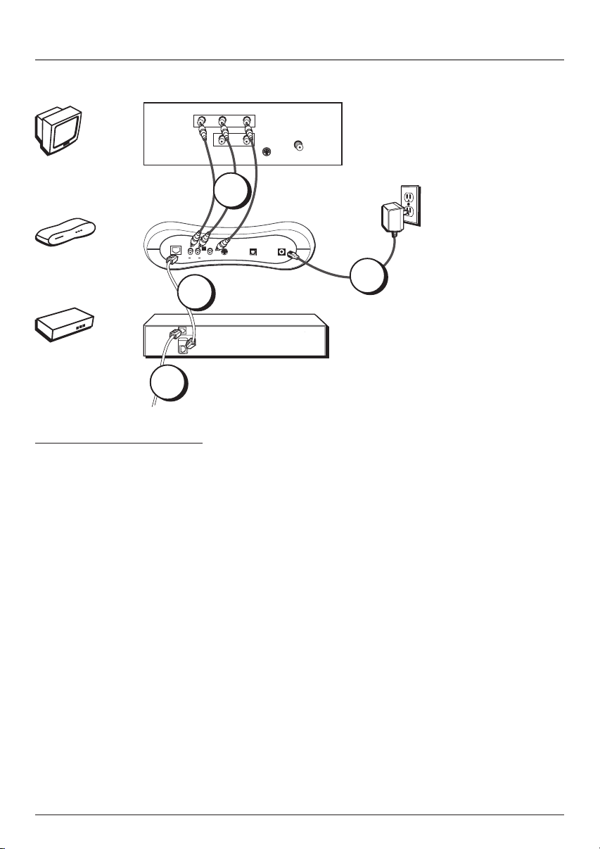
TV + IP Decoder + Modem
1. Connect the Decoder to the TV
A. Connect audio/video cables to the AUDIO OUT R and L jacks on the back of the decoder (color
coded, red and white), and to the VIDEO OUT jack (yellow). Connect the other ends of the cables
to the corresponding input jacks on the TV (sometimes labeled VIDEO, AUDIO L/MONO, and
AUDIO R).
B. If your TV doesn’t have audio/video input jacks, you need to use an RF modulator (not included).
Connect the three-pronged end of the modulator cable into the AUDIO OUT L, RF MOD, and
VIDEO jacks on the back of the decoder. Then use a coaxial cable to connect the Out to TV jack
on the modulator to your TV’s antenna in jack (sometimes labeled CABLE/ANTENNA).
Note: If your TV has an S-Video input, we recommend you make the video connection by using this jack instead of the
video jack. Remember to connect audio cables for this connection as S-Video only carries the picture signal, not the
sound.
2. Connect the ethernet cable to the IP Decoder
Connect one end of a standard CAT-5 ethernet cable (not included) to the ETHERNET jack on the
modem and the other end to the ETHERNET jack on the decoder.
3. Connect the DSL line to the DSL Modem
Connect the DSL line from the wall jack to the DSL LINE IN jack on your modem.
4. Plug the power supply into the IP Decoder power jack and into an AC outlet.
2
DSL LINE
IN
ETHERNET
3
Caution: To reduce
the risk of fire, use
only No. 26 AWG or
larger DSL
telecommunication
line cord.
Go To Page 10
Chapter 1 5
Illustrations contained in this document are for representation only.
Page 8
Chapter 1: Connections and Setup
TV
AUDIO
VIDEO
L/ MONO
R
IN
TV
L
OUT
S-VIDEO
CABLE/
ANTENNA
The back of your
TV might not look
exactly like the
one shown here.
VCR
IP Decoder
Modem
VCR
IP DECODER
ETHERNET
MODEM
4
1B
1A
The back of your
VCR might not
AUDIO
OUT
VIDEO
ANT. IN
R
L
RF OUT
IN
look exactly like
the one shown
here.
2A
RF
MOD
R
L
AUDIO
VIDEO
3
DSL LINE
IN
ETHERNET
S-VIDEO
DIGITAL
POWER
AUDIO
5
Caution: To reduce
the risk of fire, use
only No. 26 AWG or
larger DSL
telecommunication
line cord.
From DSL or other Broadband Connection
6 Chapter 1
Illustrations contained in this document are for representation only.
Page 9

Chapter 1: Connections and Setup
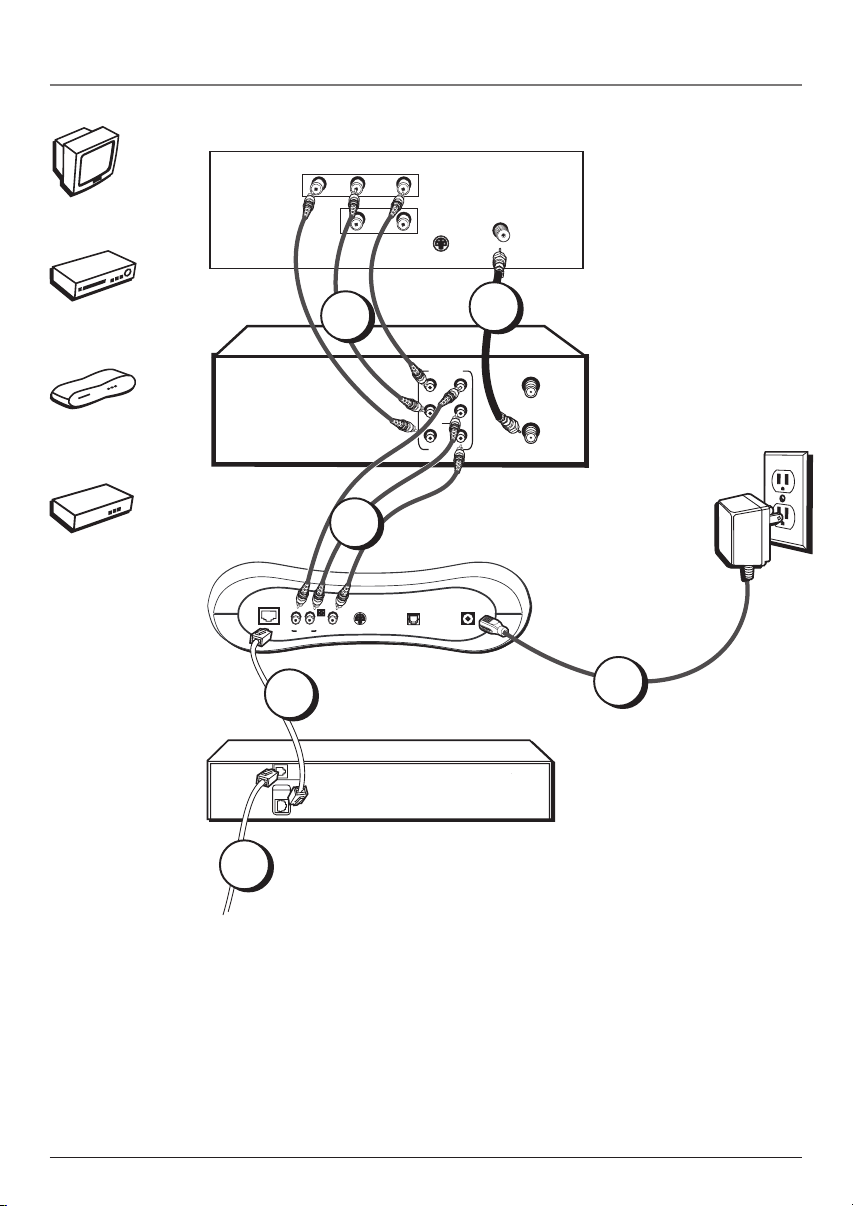
TV + VCR + IP Decoder + Modem
1. Connect the VCR to the TV
A. Connect one end of the RF coaxial cable to the RF OUT jack on the back of the VCR and the
other end to the TV’s antenna in jack (sometimes labeled CABLE/ANTENNA).
– OR –
B. Connect audio/video cables to the AUDIO OUT R and L jacks on the back of the VCR (color
coded, red and white), and to the VIDEO OUT jack (yellow). Connect the other ends of the cables
to the corresponding input jacks on the TV (sometimes labeled VIDEO, AUDIO L/MONO, and
AUDIO R).
2. Connect the IP Decoder to the VCR
A. Connect audio/video cables to the AUDIO OUT R and L jacks on the back of the decoder (color
coded, red and white), and to the VIDEO OUT jack (yellow). Connect the other ends of the cables
to the corresponding input jacks on the VCR (sometimes labeled VIDEO, AUDIO L/MONO, and
AUDIO R).
– OR –
B. If your TV doesn’t have audio/video input jacks, you need to use an RF modulator (not included).
Connect the three-pronged end of the modulator cable into the AUDIO OUT L, RF MOD, and
VIDEO jacks on the back of the decoder. Then use a coaxial cable to connect the Out to TV jack
on the modulator to your TV’s antenna in jack (sometimes labeled CABLE/ANTENNA).
Notes:
If your TV has an S-Video input, we recommend you make the video connection by using this jack instead. Remember to
connect audio cables for this connection as S-Video only carries the picture signal, not the sound.
If you have any problems with the picture quality, you may want to connect the decoder directly to your TV. You won’t be
able to record programming with this connection, however.
3. Connect the ethernet cable to the IP Decoder
Connect one end of the ethernet cable to the ETHERNET jack on the modem and the other end to
the ETHERNET jack on the decoder.
4. Connect the DSL line to the DSL Modem
Connect the DSL line from the wall jack to the DSL LINE IN jack on your modem.
5. Plug the power supply into the IP Decoder power jack and into an AC outlet.
Go To Page 10
Chapter 1 7
Illustrations contained in this document are for representation only.
Page 10
Chapter 1: Connections and Setup
TV
OUT
L / MONO
VIDEO
IN
L
OUT
S-VIDEO
1A
VCR
TV
IN
IN
OUT
TV
A/V Receiver
IP Decoder
A/V RECEIVER
COAX
OPTICAL
AUDIO
R
TAPE
CD
IN
IN
R
L
CABLE/
ANTENNA
The back of your
TV might not look
exactly like the
one shown here.
The back of your
receiver might not
look exactly like
the one shown
here.
Modem
IP DECODER
2A
2B
RF
MOD
R
ETHERNET
L
AUDIO
VIDEO
S-VIDEO
DIGITAL
POWER
AUDIO
5
MODEM
3
Caution: To reduce
DSL LINE
IN
ETHERNET
the risk of fire, use
only No. 26 AWG or
larger DSL
telecommunication
line cord.
4
From DSL or other Broadband Connection
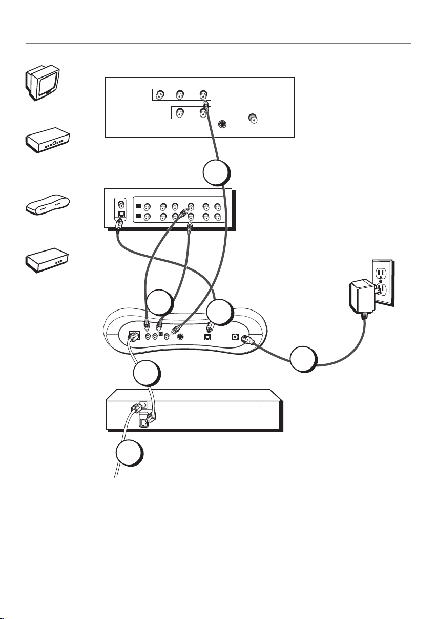
Please Read This Before Using the DIGITAL AUDIO OUT Jack!
This unit’s digital output jack is designed for a connection to a Dolby Digital receiver or decoder. Older digital
equipment may not be compatible with the Dolby Digital bitstream. Such a connection can create a high level of
noise that may be harmful to your ears, and could damage headphones or speakers.
8 Chapter 1
Illustrations contained in this document are for representation only.
Page 11

Chapter 1: Connections and Setup
TV + A/V Receiver + IP Decoder + Modem
1. Connect the Decoder to the TV
A. Connect the video cable to the VIDEO OUT jack (yellow) on the back of the decoder and the
other end of the cable to the corresponding input jack on the TV (sometimes labeled VIDEO).
B. If your TV doesn’t have a video input jack, you need to use an RF modulator (not included).
Connect the three-pronged end of the modulator cable into the AUDIO OUT L, RF MOD, and
VIDEO jacks on the back of the decoder. Then use a coaxial cable to connect the Out to TV jack
on the modulator to your TV’s antenna in jack (sometimes labeled CABLE/ANTENNA).
Note: If your TV has an S-Video input, we recommend you make the video connection by using this jack instead.
Remember to connect audio cables for this connection as S-Video only carries the picture signal, not the sound.
2. Connect the A/V Receiver to your Decoder
A. Connect audio/video cables to the AUDIO OUT R and L jacks on the back of the decoder (color
coded, red and white). Connect the other ends of the cables to the corresponding input jacks on your
A/V receiver (sometimes labeled VIDEO, AUDIO L/MONO, and AUDIO R). You may also want to
connect video to your receiver (or TV using instructions on the previous pages).
– OR –
B. If you have an audio/video receiver with Dolby* Digital or a digital optical jack, remove the
protective cap from the OPTICAL DIGITAL AUDIO OUT jack on the back of the decoder (if necessary)
and also remove the protective caps from your digital optical cable.
Connect one end of the digital optical cable to the OPTICAL AUDIO OUT jack on the back of the
decoder and the other end to the corresponding input jack on your A/V receiver (sometimes labeled
OPTICAL IN). You may also want to connect video to your receiver (or TV using instructions on the
previous pages).
3. Connect the ethernet cable to the IP Decoder
Connect one end of a standard CAT-5 ethernet cable (not included) to the ETHERNET jack on the
modem and the other end to the ETHERNET jack on the decoder.
4. Connect the DSL line to the DSL Modem
Connect the DSL line from the wall jack to the DSL LINE IN jack on your modem.
5. Plug the power supply into the IP Decoder power jack and into an AC outlet.
Go To Page 10
*Manufactured under license from Dolby Laboratories. “Dolby” and the double-D symbol are trademarks of
Dolby Laboratories.
Chapter 1 9
Illustrations contained in this document are for representation only.
Page 12

Chapter 1: Connections and Setup
Turn on the TV and IP Decoder
1. Turn on the TV (if the TV you’ve connected to the decoder is a compatible RCA, GE, or Proscan TV,
press the TV button on the remote packed with your decoder).
2. Tune the TV to the correct Video Input Channel.
• If you used a coaxial cable (with optional RF modulator) to connect your decoder to your TV,
tune the TV to channel 3 or 4.
• If you used audio/video or S-video cables to connect your decoder, tune the TV to its Video
Input Channel (see page 26).
Put Batteries in the Remote Control
Insert the batteries matching the polarities (+ and –) on the batteries with the diagram in the battery
compartment.
View
Save
Stop
Esc
Tools Back
Tools
Web
Back
Stop
Bookmark
Bookmark
Refresh
Exit
~
`
tab
caps
shift
Close
$
!
%
#
@
4
1
5
3
2
Q
W
E
R
F
A
S
D
C
Z
X
V
View
History
Open
^
6
T
G
B
Save
Bookmark
Bookmark
Shuffle
Mag
Text
•
&
)
(
*
7
0
9
8
P
O
U
I
Y
:
;
J
KL
H
<
>
,
.
M
N
Menu Home
alt
ctrl
On Off
Email Info
History
Guide
Info Home
Menu
_
+
+
CH
delete
-
=
|
}
{
-
CH
\
]
[
ok
Top
"
Page
'
enter
Up
End
?
Page
/
shift
Down
Video
Put Batteries in the Optional Wireless Keyboard
Insert the batteries matching the polarities (+ and –) on the
batteries with the diagram in the battery compartment.
Check with your service provider about purchasing the
optional wireless keyboard to make email and web surfing
easier.
10 Chapter 1
Illustrations contained in this document are for representation only.
Page 13

AUX ON • OFF TV
VIDEO WEB EMAIL VOD
HOMEMUTE
CH +
VOL
MENUGUIDE
INFO
OK
EXIT•CLEARBACK
Indicator
VOL
CH -
TOOLS
KEYBD
SELECT
123
456
789
AUDIO•INPUT ANTENNA
0
REV•REPLAY FWD•SKIPPLAY
RECORD PAUSESTOP
Note: The TV and AUX buttons also turn
on most RCA, GE, and Proscan, products.
Tip
To turn off most RCA, GE, and Proscan
components that are connected to the
decoder, press ON•OFF twice within two
seconds.
This feature only works with some RCA, GE,
and Proscan products.
Chapter 2: The Remote Control
The Buttons on the Remote Control
(0-9) Number buttons Select channels by pressing the
number buttons.
Red, green, yellow, and blue buttons (at the bottom of the
remote) Specific functions defined by your service provider.
ANTENNA In decoder mode, turns off the decoder signal to
allow other signals to pass through. In VCR mode, functions
as the TV/VCR button.
Arrows Move the on-screen highlight, and enter data such
as letters or numbers in certain menus.
AUDIO•INPUT In decoder mode, changes the program’s
audio language, if available. In VCR or TV mode, selects
between the Video Input Channel and the tuner for
compatible components. Video Input Channel refers to the
signal coming from the component connected to the audio/
video input jacks on the VCR or TV.
AUX Puts the remote in AUX mode. Can also be programmed
to operate some compatible products (A/V receiver, DVD, VCR,
etc).
BACK In Web mode, goes to the previous web page. In
menus, goes back to the previous screen or menu. In TV mode,
may return to the previously viewed channel.
CH + and CH – Selects next higher or lower channel in the
channel list.
EMAIL Turns on the decoder and goes to your email
account, if your service provider offers one.
EXIT•CLEAR Exits or clears menus.
FWD•SKIP Fast forwards video in stop mode. This button
also searches forward if pressed during playback.
GUIDE Displays the decoder program guide, if your service
provider offers one.
HOME In Web mode, takes you to your home page.
Indicator Indicates the programming mode when
programming the remote to control components.
INFO Shows on-screen information of the decoder, VCR, TV,
DVD player, etc. (whichever component is set as the remote
control’s active device).
KEYBD Brings up the on-screen keyboard or removes it. Also
acts as an enter button when using the on-screen keyboard.
MENU Displays the on-screen menu system.
MUTE Reduces the TV’s volume to a minimum level on
compatible TVs or A/V receivers.
Chapter 2 11
Illustrations contained in this document are for representation only.
Page 14

Chapter 2: Remote Control
OK•SELECT In on-screen menus, this button acts as an
AUX ON • OFF TV
VIDEO WEB EMAIL VOD
CH +
VOL
CH -
TOOLS
KEYBD
OK
SELECT
EXIT•CLEARBACK
123
456
789
AUDIO•INPUT ANTENNA
0
REV•REPLAY FWD•SKIPPLAY
RECORD PAUSESTOP
HOMEMUTE
VOL
MENUGUIDE
INFO
Enter button (used in conjunction with the remote control’s
arrow buttons). This button selects the highlighted on-screen
menu item.
ON•OFF Turns the component on or off when the remote
control is set to operate that component.
PAUSE Pauses playback or recording.
PLAY Plays video.
VOD Turns on the decoder and starts the Video-on-Demand
service, if available from your service provider.
RECORD Starts record mode for a compatible VCR.
REV•REPLAY Rewinds video or tape when in stop mode.
Searches backward during playback mode.
STOP Stops the current function (record, playback, rewind,
etc).
TOOLS Brings up the browser toolbar or removes it.
VIDEO Turns on the decoder in TV mode and shows TV
programming.
TV Turns on a compatible RCA, GE, or Proscan TV and puts
the remote control in TV-operating mode. Also used with the
ON•OFF button to turn on/off a different brand of TV (if
programmed).
VOL < and > Raises and lowers the volume of some
compatible TVs or A/V receivers (if programmed).
WEB Turns on the decoder in Web mode.
Note: If you press a button when the
batteries are low, the indicator flashes.
12 Chapter 2Illustrations contained in this document are for representation only.
Page 15

Chapter 2: Remote Control
Using the INPUT Button
Use the INPUT button to scroll through the available Video Input Channel sources for a TV or VCR and
regular broadcast signals. The Video Input Channels allow you to view images from a component
connected to the TV or VCR (such as a camcorder or DVD player).
1. Press the remote control’s TV or AUX button (if programmed) to enter the corresponding mode. Make
sure the component is turned ON.
2. Press the remote control’s INPUT button to tune to the Video Input Channel.
3. To tune back to the broadcast signal you were previously watching through the TV or VCR, press the
INPUT button again.
Volume Punchthrough
You may find this feature helpful if you’ve connected your components to an audio/video receiver (A/V
receiver) or amplifier, but you want to use the decoder’s remote control to operate the volume.
Let’s say you’ve connected your IP video decoder to your audio/video receiver. You’ve also programmed
your decoder remote control to operate your receiver. Since the decoder gets its volume through the
receiver, you would have to tell the remote you wanted to change the volume on the receiver each time
by pressing the AUX button first. With Volume Punchthrough, you can control the receiver’s volume,
even when the remote is in decoder mode. Just use the volume buttons as normal, and you’ll change the
receiver’s volume automatically (or whatever volume component you used last).
IMPORTANT: You must first program the AUX button on the decoder’s remote control to operate your audio
receiver or amplifier. Go to page 14 for instructions. If you can’t program this remote to operate your audio
receiver, Volume Punchthrough won’t work.
Chapter 2 13
Illustrations contained in this document are for representation only.
Page 16

Chapter 2: Remote Control
Programming the Remote to Operate Other Components
The universal remote can be programmed to operate most brands of remote controllable components.
The remote is already programmed to operate most RCA, GE, and Proscan components.
Find Out If You Need to Program the Remote
To determine whether the universal remote needs to be programmed for your component, turn the
component ON. For example, to program the remote for a TV, turn on the TV. Point the remote at the TV,
and press the TV button. Then press ON•OFF or CH + (channel up) or CH – (channel down) to see if the
TV responds to the remote commands. If the component does not respond, the remote needs to be
programmed.
Programming the Remote
There are two ways to program the remote control: direct entry and automatic code search.
Important
You must continue pressing the component
button while you enter the code.
Let’s say you have a Zenith TV. To program the
universal remote to operate the TV, you would:
Press and hold the TV button while you enter
the first code listed for Zenith in the TV Codes
column.
Release the TV button. Press ON•OFF to see if
the TV responds. If it doesn’t, follow the same
steps, but enter the second code for Zenith TVs
instead of the first.
Note
Some of the remote’s buttons might operate
differently for other components, especially
when you’re using another component’s menu
system.
Using Direct Entry
1. Turn on the component to be programmed.
2. Look up the brand and code number(s) for the component
on the code list in this section.
3. Press and hold the component button you want to
program on the remote (TV or AUX).
4. Enter the 4-digit code from the remote control code list
on the following pages. If the indicator flashes, you have
either entered an invalid code or the button isn’t
programmable.
5. Release the component button, point the remote at the
component, then press ON•OFF to see if the component
responds to the command. If it doesn’t, try pressing the
component button and then ON•OFF again.
• If you get no response, repeat these steps using the next
code listed for your brand, until the component responds
to the remote commands.
• If you try all the codes for your component brand and
none work, try the automatic code search method. If
automatic code search doesn’t work, the remote is not
compatible with your component.
14 Chapter 2Illustrations contained in this document are for representation only.
Page 17

Chapter 2: Remote Control
ON • OFF
AUX
TV
Indicator
EXIT•CLEAR
PLAY
REV•REPLAY
STOP
Use these buttons when
you program the remote.
Important: The remote may not be
compatible with all models of all
brands of components. It may not
operate all functions of the remote
that came with your component.
Note: If you need to replace the
batteries in the remote, don’t
press any buttons. If you do,
you’ll have to reprogram the
remote.
Using Automatic Code Search to Program Your TV
You can program the remote to operate your TV. To stop the
automatic code search without programming your TV, press
EXIT•CLEAR until the indicator on the remote turns off.
Note: AUX can’t be programmed using the automatic code search
method.
1. Turn on your TV.
2. Press and hold the TV button. While holding TV, press and hold
ON•OFF until the indicator on the remote turns on, then release
both buttons.
3. Point the remote at the TV. Press and release PLAY, then wait 5
seconds or until the indicator on the remote stops flashing.
At this point the remote is searching for the correct code to
program. If, after 5 seconds, the TV does not turn off, press PLAY
again to search the next set of codes.
Continue pressing PLAY until the TV turns off or you have
searched through all of the codes. There are 20 total sets of codes.
If the TV does not turn off after pressing PLAY 20 times, then the
remote can’t be programmed to operate it.
If the TV does turn off:
1. Press and release REVERSE, then wait 2 seconds. Repeat this step
until it turns back ON.
2. Press and hold STOP until the indicator on the remote turns off.
How to Use the Remote After You’ve Programmed It
Because this universal remote can control several different components (TV, DVD, VCR, A/V receiver) it
uses operational modes triggered by the component buttons. For example, if you want the remote to
control the TV, press the TV button to put the remote into TV mode.
1. Press the appropriate component button (TV, AUX, VIDEO, Web, etc.) to set the remote to control the
component.
2. Press ON•OFF to turn the component ON or OFF.
3. Use the remote buttons that apply to that component.
Notes:
• The remote may not be compatible with all brands and models of components. It also may not operate
all functions of the remote that came with your component.
• If you keep pressing buttons and nothing happens, the remote is probably in the wrong mode. You
must press the component button that matches the component you want to operate (i.e., if you want
to operate the TV, press TV on the remote control to put the remote in TV mode.)
Chapter 2 15
Illustrations contained in this document are for representation only.
Page 18

Chapter 2: Remote Control
Code List
TV Codes
Abex ............................................................................... 1172
Admiral .................................................. 1001, 1173, 1211
Adventura ..................................................................... 1174
Aiko ............................................................................... 1016
Akai ............................................................................... 1002
Alleron .......................................................................... 1046
Amtron ......................................................................... 1038
Anam National ............. 1003, 1038, 1192, 1193, 1194
AOC ......... 1004, 1005, 1006, 1007, 1175, 1176, 1195
Audiovox ...................................................................... 1038
Belcor ............................................................................ 1004
Bell & Howell ...................................... 1001, 1083, 1162
Bradford ....................................................................... 1038
Brokwood ..................................................................... 1004
Candle ........................................ 1004, 1006, 1008, 1174
Celebrity ....................................................................... 1002
Centurion ..................................................................... 1009
Citizen ...................................... 1004, 1006, 1008, 1016,
Colortyme ............................................. 1004, 1006, 1010
Concerto .......................................................... 1004, 1006
Contec/Cony ............................ 1012, 1013, 1014, 1038
Craig .............................................................................. 1038
Crown ................................................................ 1038, 1171
Curtis-Mathes ................................... 1000, 1004, 1006,
CXC ................................................................................ 1038
Daewoo ............................................... 1004, 1005, 1006,
Daytron ................................................. 1004, 1006, 1171
Dimensia ...................................................................... 1000
Dumont ............................................................. 1004, 1151
Dynatech .......................................................................1178
Electronband ............................................................... 1002
Electrohome ..... 1003, 1004, 1006, 1019, 1020, 1022
Emerson ........... 1004, 1006, 1012, 1023, 1024, 1025,
1026, 1027, 1028, 1029,1030, 1031, 1032, 1033,
1034, 1035, 1036, 1037, 1038, 1039, 1041, 1042,
1043, 1044, 1046, 1047, 1123, 1124, 1162, 1171,
Envision ............................................................ 1004, 1006
Fisher .............................. 1048, 1049, 1051, 1162, 1180
Fujitso ........................................................................... 1046
Funai ................................................................. 1038, 1046
Futuretec ..................................................................... 1038
GE .................................. 1000, 1003, 1004, 1006, 1022,
1052, 1054,1055, 1087, 1164, 1165, 1166, 1167,
Gibralter ............................................................ 1004, 1151
Goldstar .....................................1004, 1005, 1006, 1012
Grundy ................................................... 1038, 1046, 1171
Hallmark .......................................................... 1004, 1006
Harvard ......................................................................... 1038
Hitachi .... 1004, 1006, 1012, 1013, 1014, 1059,1060,
1139, 1140, 1141, 1142, 1143, 1144, 1145,1146,
IMA ................................................................................ 1038
Infinity .......................................................................... 1062
Janeil ..............................................................................1174
JBL ................................................................................. 1062
JCB ................................................................................. 1002
JC Penney ......... 1000, 1004, 1005, 1006, 1008, 1022,
1052, 1054, 1058, 1063, 1064, 1072, 1087, 1105,
1038, 1105, 1171, 1174, 1177
1015, 1105, 1162, 1171, 1212
1016, 1017, 1018, 1127, 1171, 1196
1177, 1179, 1191, 1208
1168, 1181, 1213
1019, 1056, 1057, 1058, 1155, 1156,
1061, 1135, 1136, 1137, 1138,
1148, 1150, 1179, 1198, 1199
1128, 1171, 1172, 1181, 1201
1171, 1172
Jensen ............................................................... 1004, 1006
JVC ................................. 1012, 1013, 1014, 1054, 1060,
1065, 1066, 1067, 1157, 1158, 1159, 1182
Kawasho ................................................1002, 1004, 1006
Kenwood ............................................... 1004, 1006, 1019
Kloss Novabeam ..................... 1068, 1069, 1174, 1183
KTV ............................................... 1038, 1070, 1171, 1177
Loewe ............................................................................ 1062
Logik .............................................................................. 1083
Luxman ............................................................. 1004, 1006
LXI ......................................................... 1000, 1006, 1049,
1062, 1071, 1072, 1073, 1162, 1181, 1207
Magnavox ................................ 1004, 1006, 1008, 1019,
1062, 1068,1069,1075, 1076, 1077, 1088, 1130,
11 31, 1132, 1133, 1134, 1183, 1219,1235
Majestic ....................................................................... 1083
Marants ........................................................................ 1062
Marantz ..................................... 1004, 1006, 1062, 1078
Megatron ......................................................... 1006, 1059
Memorex ....................... 1001, 1006, 1082, 1083, 1162
MGA ....... 1004, 1005, 1006, 1019, 1022, 1051, 1079,
Midland ........................... 1054, 1151, 1171, 1172, 1181
Minutz .......................................................................... 1052
Mitsubishi ................................ 1004, 1005, 1006, 1019,
1022, 1051, 1079, 1080, 1081, 1082, 1125
Montgomery Ward .................................................... 1083
Motorola ........................................................... 1003, 1173
MTC ............................................ 1004, 1005, 1006, 1105
Multitech ..................................................................... 1038
Multivision .................................................................. 1084
NAD ............................................. 1006, 1071, 1072, 1185
NEC ................................ 1003, 1004, 1005, 1006, 1200
Nikko ................................................................. 1006, 1016
NTC ................................................................................ 1016
Onwa ............................................................................. 1038
Optimus ......................................................................... 1185
Optonica ........................................................... 1095, 1173
Orion .................................................................. 1035, 1191
Panasonic ...................... 1003, 1054, 1062, 1170, 1214
Philco .... 1003, 1004, 1005, 1006, 1008, 1012, 1019,
Philips ... 1003, 1004, 1008, 1012, 1019, 1062, 1068,
Pilot .................................................................... 1004, 1171
Pioneer ... 1004, 1006, 1090, 1091, 1092, 1179, 1185
Portland .......................... 1004, 1005, 1006, 1016, 1171
Price Club ..................................................................... 1105
Prism ............................................................................. 1054
ProScan ............................................................. 1000, 1181
Proton ........................................ 1004, 1006, 1012, 1093
Pulsar ................................................................. 1004, 1151
Quasar ....................................... 1003, 1054, 1070, 1094
Radio Shack/Realistic .................................. 1000, 1004,
RCA .................... 1000, 1003, 1004, 1005, 1006, 1007,
Runco ............................................................................. 1151
Sampo ......................................... 1004, 1006, 1171, 1172
Samsung 1004, 1005, 1006, 1012, 1015, 1019,1104,
Samsux .......................................................................... 1171
Sansui ............................................................................ 1191
Sanyo ................................................... 1004, 1048, 1049,
Scotch ........................................................................... 1006
1062, 1068, 1069, 1075, 1077, 1183
1069, 1075, 1076, 1086, 1087, 1088, 1089
1006, 1012, 1038, 1049, 1095, 1162, 1171, 1172
1019,1096, 1098, 1099, 1100, 1101,
1102, 1103, 1129, 1179, 1181, 1187,
1188,1190, 1202, 1203, 1215, 1233
1105, 1106, 1171, 1172, 1204
1080, 1107, 1108, 1162, 1169, 1180
1080, 1082
Scott ....... 1004, 1006, 1012, 1024, 1035, 1038, 1046
Sears ..... 1000, 1004, 1006, 1013, 1014, 1019, 1046,
1048, 1049, 1051, 1066, 1071, 1072, 1109, 1110,
Sharp ....... 1004, 1006, 1012, 1029, 1095, 1111, 1112,
Shogun ......................................................................... 1004
Signature .............................................. 1001, 1083, 1115
Simpson ........................................................................ 1008
Sony .......................................... 1002, 1205, 1216, 1218
Soundesign ................... 1004, 1006, 1008, 1038, 1046
Squareview ...................................................................1189
SSS ..................................................................... 1004, 1038
Starlite .......................................................................... 1038
Supre-Macy ................................................................. 1174
Supreme ....................................................................... 1002
Sylvania 1004, 1006, 1008, 1019, 1062, 1068, 1069,
1075, 1076, 1077, 1088, 1116, 1161, 1183
Symphonic ............................................ 1033, 1038, 1189
Tandy ..............................................................................1173
Tatung ........................................................................... 1003
Technics ........................................................................ 1054
Techwood ............................................. 1004, 1006, 1054
Teknika . 1004, 1005, 1006, 1008, 1012, 1013, 1014,
1016, 1038, 1046, 1076, 1082, 1083, 1105,1170,
Telecaption ................................................................... 1117
TMK ................................................................... 1004, 1006
Toshiba ..... 1049, 1071, 1072, 1105, 1109, 1117, 1118,
Totevision ...................................................................... 1171
Universal .......................................................... 1052, 1087
Victor ................................................................. 1066, 1182
Vidtech ................................................. 1004, 1005, 1006
Viking ............................................................................. 1174
Wards .... 1000, 1001, 1004, 1005, 1006, 1019, 1024,
1033, 1046, 1052, 1062, 1068, 1069, 1075, 1076,
Yamaha ..................................... 1004, 1005, 1006, 1019
Zenith ...... 1004, 1083, 1151, 1152, 1153, 1154,1210,
1162, 1180, 1181, 1189
1113, 1122, 1171, 1173
11 71
1160, 1162
1083, 1087, 1088, 1095, 1119, 1120
1217
VCR Codes
Admiral ......................................................................... 2132
Adventura .................................................................... 2026
Aiko ............................................................................... 2027
Aiwa .............................................................................. 2026
Akai .............................. 2003, 2004, 2005, 2007, 2008,
................................................................... 2111, 2112, 2113
American High ........................................................... 2021
Asha .............................................................................. 2013
Audio Dynamics ............................................. 2009, 2010
Audiovox ...................................................................... 2014
Bell & Howell .............................................................. 2011
Beaumark ..................................................................... 2013
Broksonic ......................................................... 2012, 2025
Calix .............................................................................. 2014
Candle ...................................... 2013, 2014, 2015, 2016,
................................................................ 2017, 2018, 2019
Canon ..................................................... 2021, 2022, 2114
Capehart ........................................................... 2020, 2110
Carver ........................................................................... 2062
CCE .................................................................... 2027, 2061
Citizen ............................................................. 2013, 2014,
Colortyme .................................................................... 2009
2015, 2016, 2017, 2018, 2019, 2027
continued on next page
16 Chapter 2Illustrations contained in this document are for representation only.
Page 19

Chapter 2: Remote Control
Colt ................................................................................ 2061
Craig .......................................... 2013, 2014, 2023, 2061
Curtis-Mathes ................................... 2000, 2009, 2013,
2016, 2018, 2021, 2022, 2024, 2115, 2131
Cybernex ...................................................................... 2013
Daewoo ....................... 2015, 2017, 2019, 2025, 2026,
Daytron ......................................................................... 2110
DBX .................................................................... 2009, 2010
Dimensia .......................................................... 2000, 2131
Dynatech ...................................................................... 2026
Electrohome .................................................... 2014, 2029
Electrophonic ............................................................. 2014
Emerson 2012, 2014, 2015, 2021, 2024, 2025, 2026,
2029, 2030, 2031, 2032, 2033, 2034, 2035, 2036,
2037, 2038, 2039, 2040, 2041, 2042, 2044, 2045,
2046, 2047, 2065, 2113, 2116, 2117, 2130
Fisher .................................................... 2011, 2023, 2048,
Fuji ...................................................................... 2021, 2119
Funai ............................................................................. 2026
Garrard ......................................................................... 2026
GE ......................................................... 2000, 2001, 2013,
Goldstar ........................ 2009, 2014, 2018, 2054, 2131
Gradiente ..................................................................... 2026
Harley Davidson ......................................................... 2026
Harman Kardon .......................................................... 2009
Harwood ...................................................................... 2061
Headquarter ................................................................. 2011
Hitachi ............................................................. 2055, 2056,
Hi-Q .............................................................................. 2023
Instant Replay ............................................................ 2021
JCL ................................................................................. 2021
JC Penney ................................. 2009, 2010, 2011, 2013,
Jensen .................................................... 2055, 2056, 2111
JVC ....................... 2009, 2010, 2011, 2018, 2111, 2123
Kenwood .............................................. 2009, 2010, 2011,
KLH ................................................................................ 2061
Kodak ................................................................ 2014, 2021
Lloyd .............................................................................. 2026
Logik .............................................................................. 2061
LXI .................................................................................. 2014
Magnavox ........................................... 2021, 2022, 2062,
Magnin ......................................................................... 2013
Marantz ................................................ 2009, 2010, 2011,
Marta ............................................................................ 2014
Masushita .................................................................... 2021
Mei ................................................................................ 2021
Memorex .......................................................... 2011, 2013,
MGA ....................................................... 2029, 2065, 2113
MGN Technology ....................................................... 2013
Midland ........................................................................ 2053
Minolta ................................................. 2055, 2056, 2107
Mitsubishi ....... 2029, 2055, 2056, 2065, 2066, 2067,
Montgomery Ward ........................................ 2075, 2132
Motorola .......................................................... 2021, 2132
MTC ................................................................... 2013, 2126
Multitech ..................... 2013, 2016, 2026, 2053, 2061
NEC ................................. 2009, 2010, 2011,2016, 2018,
Nikko ............................................................................. 2014
Noblex .......................................................................... 2013
Olympus ....................................................................... 2021
Optimus ............................................................ 2014, 2132
2021, 2022, 2053, 2115, 2120, 2131
2014, 2021, 2022, 2055, 2056,
2014, 2021, 2023, 2026, 2104, 2132
2068, 2070, 2071, 2072, 2073, 2074, 2106, 2113,
2064, 2076, 2078, 2079, 2111, 2123
2027, 2028, 2110
2049, 2050, 2051, 2052, 2118
2057, 2107, 2111, 2120, 2122
2058, 2059, 2060, 2107, 2118
2016, 2018, 2111, 2123
2063, 2104, 2105, 2108, 2124
2016, 2018, 2021, 2062, 2064
2123
Optonica ...................................................................... 2096
Panasonic .......... 2021, 2022, 2109, 2125, 2126, 2127
Pentax ............................ 2016, 2055, 2056, 2107, 2120
Pentex Research ........................................................ 2018
Philco ........................................ 2021, 2022, 2062, 2063
Philips ....................................... 2021, 2062, 2096, 2124
Pilot ............................................................................... 2014
Pioneer ......................... 2010, 2055, 2080, 2081, 2123
Portland ..................................... 2016, 2017, 2019, 2110
PROSCAN ............................................. 2000, 2001, 2131
Protec ............................................................................ 2061
Pulsar ............................................................................ 2104
Quarter .......................................................................... 2011
Quartz ............................................................................ 2011
Quasar .................................................. 2021, 2022, 2125
RCA ....... 2000, 2001, 2003, 2013, 2021, 2055, 2056,
2082, 2083, 2084, 2085, 2086, 2087, 2088, 2089,
2090, 2091, 2107, 2115, 2120, 2125, 2131, 2133
Radioshack/Realistic . 2011, 2013, 2014, 2021, 2022,
2023, 2026, 2029, 2049, 2050, 2096, 2132
Radix ............................................................................. 2014
Randex .......................................................................... 2014
Ricoh ............................................................................. 2128
Runco ............................................................................ 2104
Samsung ........... 2005, 2013, 2015, 2033, 2053, 2112
Sanky ................................................................ 2104, 2132
Sansui ......................................... 2010, 2092, 2111, 2123
Sanyo ..................................................... 2011, 2013, 2023
Scott .......................................... 2012, 2015, 2025, 2032
Sears .............................. 2011, 2014, 2021, 2023, 2048,
2049, 2050, 2051, 2055, 2056, 2107, 2118
Sharp ..... 2017, 2029, 2094, 2095, 2096, 2097, 2131
Shintom .................................... 2004, 2056, 2061, 2098
Shogun ......................................................................... 2013
Signature ..................................................................... 2131
Singer .................................................... 2021, 2061, 2128
Sony ........................................... 2004, 2098, 2099, 2119
STS ...................................................................... 2021, 2107
Sylvania ........................................................... 2021, 2022,
Symphonic ................................................................... 2026
Tandy ..............................................................................2011
Tashiko .......................................................................... 2014
Tatung ............................................................................ 2111
TEAC ....................................................... 2026, 2085, 2111
Technics ............................................................. 2021, 2109
Teknika .......................... 2014, 2021, 2026, 2100, 2129
TMK ....................................................... 2013, 2024, 2047
Toshiba ................................................ 2015, 2049, 2051,
................................................... 2055, 2065, 2093, 2116
Totevsion .......................................................... 2013, 2014
Unitech ......................................................................... 2013
Vector Research ...................... 2009, 2010, 2015, 2016
Victor ............................................................................ 2010
Video Concepts ........... 2009, 2010, 2015, 2016, 2113
Videosonic ................................................................... 2013
Wards ........................................2013, 2014, 2015, 2021,
2096, 2101, 2102, 2103, 2107, 2116, 2132
XR-1000 ............................................... 2021, 2026, 2061
Yamaha .......................... 2009, 2010, 2011, 2018, 2111
Zenith ............................ 2004, 2098, 2104, 2119, 2128
2038, 2065, 2093, 2116
2026, 2062, 2063, 2065, 2124
2023, 2026, 2029, 2055, 2056, 2061,
DVD codes
Aiwa .............................................................................. 3009
GE .................................................................................. 3000
Hitachi .......................................................................... 3008
JVC ..................................................................... 3002, 3010
Konka ................................................................. 3011, 3012
Magnavox .................................................................... 3003
Mitsubishi .................................................................... 3004
Panasonic ..................................................................... 3013
Philips ....................................... 3003, 3019, 3021, 3022
Pioneer ......................................................................... 3005
PROSCAN ..................................................................... 3000
RCA .................................................................... 3000, 3001
Sanyo ............................................................................ 3014
Shinco ........................................................................... 3001
Sony ...................................................... 3006, 3015, 3016
Toshiba ................................................. 3007, 3017, 3020
Zenith ........................................................................... 3018
Audio Codes
RCA and Dimensia
AM/FM .............................................................. 4003, 4270
AUX ............................................................................... 4004
Phono ............................................................................ 4005
Tape ............................................................................... 4006
CD ........................................................... 4007, 4190, 4211
Receivers
Aiwa ........................................ 4261, 4262, 4263, 4264,
.................................................... 4265, 4266, 4267, 4277
Denon ........................................................................... 4283
Harman Kardon .......................................................... 4276
JVC ................................................................................. 4268
JVL ................................................................................. 4276
Kenwood ...................................................................... 4269
Onkyo ............................................................................ 4278
Optimus ........................................................................ 4284
Panasonic ......................................................... 4279, 4280
Pioneer ......................................................................... 4275
RCA ................................................................................ 4270
Sherwood ..................................................................... 4282
Sony ...................................................... 4271, 4272, 4281
Technics ............................................................ 4279, 4280
Wards ............................................................................ 4275
Yamaha ............................................................ 4274, 4275
CD Players
ADC ....................................................... 4200, 4201, 4220
Aiwa .................................................................. 4175, 4203
Akai ............................................................................... 4205
Denon ........................................................................... 4208
Dynatech ...................................................................... 4177
Emerson ....................................................................... 4178
Fisher .................................................... 4179, 4212, 4213
GE .................................................................................. 4216
Hitachi .......................................................................... 4180
JVC ..................................................................... 4181, 4221
Kenwood .............................................. 4183, 4222, 4224
Luxman ......................................................................... 4225
Marantz ............................................................ 4185, 4226
Mitsubishi ........................................................ 4229, 4230
MCS ............................................................................... 4228
Nakamichi ....................................................... 4232, 4233
NEC ................................................................................ 4184
Onkyo .................................................... 4186, 4234, 4235
Optimus ................................................ 4237, 4238, 4239
Panasonic ..................................................................... 4188
Pioneer ............................................................. 4189, 4240
RCA ..................................................................... 4190, 4211
Sanyo ............................................................................ 4250
Sears .............................................................................. 4207
Sherwood ..................................................................... 4243
Sony ...................................................... 4195, 4209, 4244
Teac ....................................................... 4245, 4246, 4247
Technics ........................................................................ 4197
Toshiba ......................................................................... 4231
Yamaha ................................................ 4198, 4199, 4248
Chapter 2 17
Illustrations contained in this document are for representation only.
Page 20

Chapter 3: Decoder Features
Using the Remote Control to Choose On-screen Menu Items
The technical term is “Navigation” – how you move through the on-screen menus. The theory is the
same throughout the menu screens: highlight your choice and select it.
To highlight a menu item, press the arrow buttons on the remote or the keyboard. Use the up or down
arrow button to move up or down. Use the right or left arrow button to move left or right.
To select the item that you’ve highlighted, press OK•SELECT.
For easier menu and web navigation, check with your service provider about purchasing the optional
wireless keyboard.
Note: Highlighted means that the menu item stands out from the other menu items on the list (appears darker, brighter,
or a different color).
Using the On-Screen Keyboard
The on-screen keyboard is a keyboard that appears on the screen to help you enter text on web pages or
menus. The navigation of the keyboard is very similar to remote control navigation in the menus: you
highlight the key you want to enter with the arrow buttons and press OK to select it.
•To bring up the on-screen keyboard to enter text, press the KEYBD button when a text box is
selected. When you’re finished typing the text, press KEYBD to enter it (it works the same as the
Enter button on the virtual keyboard).
•To exit the on-screen keyboard, highlight the EXIT button on the keyboard using the arrow buttons,
and press OK to select it.
If you have an optional wireless keyboard, using it to enter text will also make the on-screen keyboard
disappear.
The on-screen keyboard.
Shift, Alt, Ctrl Keys
These keys can be used in combination with other keys, just like on a standard keyboard. These keys are
only applied to the next character you type. A light on the key indicates when it’s active.
Shortcut Keys
The .gov, .org, .com, and www. keys are shortcuts for commonly used characters used in web addresses
and are added to the text box when selected.
18 Chapter 3
Illustrations contained in this document are for representation only.
Page 21

Chapter 3: Decoder Features
Chapter 3: Decoder Features
Using the Web Browser
The web browser is where you do all your internet browsing.
Not only can you surf all your favorite websites, but you can
also view and save your bookmarks, view your browsing
history, and search for new websites.
Browser Banner
The browser banner gives you information, such as how to
bring up the browser tool bar or take it away, and also the
Browser Banner
The web browser showing the browser
banner and toolbar.
Browser Toolbar
Browser Toolbar
The browser toolbar is where you enter website addresses and find the tools to navigate the websites.
Address – Where you enter your website address.
Back – Goes back to the previous page.
Refresh/Stop – Refreshes the current page if it stopped loading too soon and also stops the page from
loading if in progress.
Home – Takes you to the home web page.
Close icon – Closes the current window (if other windows are open).
Shuffle icon – Swaps open windows.
Resize text icon – Resizes the text of the page (up to 3 sizes).
Magnify icon – Magnifies the page (up to 3 levels).
More – Takes you to the More Features menu, where you can view and save bookmarks and view your
website history.
To TV – Exits the browser and takes you back to TV viewing.
loading status of the current page.
Entering a Website Address
You can enter a website directly using the browser toolbar.
1. Press the WEB button to put the decoder in web mode.
2. Press the TOOLS button (the browser toolbar appears).
3. Press KEYBD while the website address box is highlighted (the on-screen keyboard appears).
4. Use the arrow buttons on the remote control to highlight the first letter you want to enter. Keep in
mind there are shortcut keys on the bottom of the keyboard (.gov, .org, .com. www). When the key is
highlighted, press OK•SELECT on the remote to select it.
5. Continue entering all the letters until the website address is complete. Then press KEYBD (the
website loads).
Note: If you make a mistake while entering the address, use DELETE and the arrow buttons on the keyboard to correct it.
Chapter 3 19
Page 22

Chapter 3: Decoder Features
Web Page Navigation
You can use the arrow buttons on the remote or the optional wireless keyboard to move around web
pages.
To hide the browser toolbar so that you can browse the page, press the TOOLS button or use the up
arrow button to move from the toolbar to the website.
Notes:
• While the toolbar is on the screen, you can’t browse the web page or access links.
• While navigating a web page, you can only bring up the toolbar using the TOOLS button.
More Features
Viewing Your Bookmarks
View your bookmarks from the More Features menu.
1. Press the TOOLS button (the browser toolbar appears).
2. Use the arrow buttons to highlight the More button.
3. Press OK to select it (the More Features menu appears).
4. Highlight View Bookmarks, and press OK (the Bookmarks
list appears).
Selecting Bookmarks
1. Follow steps 1-4 in Viewing Your Bookmarks to bring up
the bookmarks list.
2. Use the arrow buttons to highlight the bookmark you
want.
•To go to a bookmark, highlight it, and use the left and
right arrow buttons to highlight Go to Page, then press
OK.
•To return to the browser without going to a page,
highlight the Back button, then press OK.
20 Chapter 3
Illustrations contained in this document are for representation only.
Page 23

Chapter 3: Decoder Features
Saving Your Bookmarks
1. Go to the webpage you want to save.
2. Press the TOOLS button (the browser toolbar appears).
3. Use the arrow buttons to highlight the More button.
4. Press OK to select it (the More Features menu appears).
5. Highlight Save Bookmarks. Press OK (your bookmark
saves).
Viewing Your History
1. Press the TOOLS button (the browser toolbar appears).
2. Use the arrow buttons to highlight the More button.
3. Press OK to select it (the More Features menu appears).
4. Highlight History, and press OK (the History list appears).
•To go to a page in your history, highlight the page, and
use the left and right arrow buttons to highlight Go to
Page, then press OK.
•To return to the browser without going to a page,
highlight the Back button, then press OK.
Chapter 3 21
Illustrations contained in this document are for representation only.
Page 24

Chapter 4: Additional Information
Troubleshooting
You can correct most problems you have with your product by consulting the troubleshooting list
that follows. If you need service, please contact your service provider.
Decoder Problems
Decoder won’t turn on
•Press the VIDEO button.
• Make sure the decoder is plugged in.
• Check the wall receptacle (or extension cord) to make sure it is “live” by plugging in something else.
• Something might be wrong with your remote control or keyboard. Check the remote control solutions
on the next page.
Decoder appears to be locked up
• Hold the ON•OFF button on the remote until the indicator on the front of the unit blinks 5 times. The
unit reboots.
•Verify the Power indicator is not flashing (slowly first, then blinks fast). If it is, there may be a broken
connection to the service provider or service may be momentarily unavailable. Contact your service
provider.
• Unplug the unit for a few seconds, then plug it back in and try again.
No sound, picture okay
• Maybe the sound is muted. Try pressing the volume up button to restore sound on the TV or audio
receiver.
• If using a standard video or S-video, video connection, remember to also connect the decoder’s L and
R AUDIO OUT jacks to the component’s L and R AUDIO IN jacks.
•Try changing channels.
• Check the digital audio settings if you’re using the decoder’s digital optical jack.
No picture, no sound but decoder is on
• If your decoder is connected to the CABLE/ANTENNA jack on your TV with a coaxial cable, tune the TV
to channel 3 or 4.
• If your decoder is connected to your TV with audio/video cables, tune your TV to the appropriate Video
Input Channel (see page 26).
Sound okay, picture poor
• Check connections. Make sure all of the cables are firmly connected to the jacks.
• Change the channel.
No connection after more than 5 minutes
• Make sure all connections are secure and try connecting to your service provider again. If you still
have problems connecting to the network, contact your service provider.
“Signal is Temporarily Unavailable” appears
• Change channels to see if it is a station problem. If it appears on more than one channel, there may be
a problem with the signal. Reboot the decoder by holding the ON•OFF button on the remote until the
indicator on the front of the unit blinks 5 times. The unit reboots. You may also want to unplug the
unit.
While connecting, the decoder seems to be stuck on one step for a long time
• Check the status of the indicator on the front of the decoder. If it is flashing, there is no connection
between the decoder and the modem. Make sure the modem is on and the modem and decoder are
connected properly. There may be a broken connection to the service provider or service may be
momentarily unavailable. Contact your service provider.
22 Chapter 4
Illustrations contained in this document are for representation only.
Page 25

Chapter 4: Additional Information
Remote Control or Wireless Keyboard Problems
• Something might be between the remote or keyboard and the remote sensor on the component. Make
sure there is a clear path.
• Maybe the remote isn’t aimed directly at the component (TV or decoder) that you’re trying to operate.
• Maybe remote or keyboard is not in a decoder mode. Press the VIDEO button to operate the decoder.
• Maybe batteries in remote are weak, dead, or installed incorrectly. Put new batteries in the remote. (Note,
if you remove the batteries, you may have to reprogram the remote to operate other components.) Don’t
press any buttons when removing the batteries.
• Operate the remote control or wireless keyboard at a distance of no more than 20 feet.
•You might need to drain the remote’s microprocessor: remove batteries and press the number 1 button for
at least 60 seconds. Release the 1 button, replace the batteries, and (if necessary) program the remote
again.
Care and Cleaning
CAUTION: Unplug your decoder before cleaning.
You can clean the unit as required, using a soft lint-free cloth. Be sure to occasionally dust the
ventilation slots in the cabinet to help assure adequate ventilation.
Never use strong cleaning agents, such as ammonia-based cleaners, or abrasive powder. These types of
cleaners will damage the unit.
Never place drinks or vases with water on top of the unit. This could increase the risk of fire or shock
hazard or damage to the decoder.
Service Information
If you purchased or leased your IP video decoder directly from your service provider, then warranty
service for the decoder may be provided through your service provider or its authorized representative.
For information on Ordering Service, Obtaining Customer Support, or Additional Service Information,
please contact your service provider.
Chapter 4 23
Illustrations contained in this document are for representation only.
Page 26

Chapter 4: Additional Information
FCC and Industry Canada Information
This equipment has been tested and found to comply with the limits for a Class B digital device,
pursuant to Part 15 of the FCC Rules. These limits are designed to provide reasonable protection against
harmful interference in a residential installation. This equipment generates, uses, and can radiate radio
frequency energy and, if not installed and used in accordance with the instructions, may cause harmful
interference to radio communications. However there is no guarantee that interference will not occur in
a particular installation. If this equipment does cause harmful interference to radio or television
reception, which can be determined by turning the equipment off and on, the user is encouraged to try
and correct the interference by one or more of the following measures:
• Reorient or relocate the receiving antenna.
• Increase the separation between the equipment and receiver.
• Connect this equipment into an outlet on a circuit different from that to which the receiver is
connected.
• Consult your service provider or an experienced radio/TV technician for help.
FCC regulations state that unauthorized changes or modifications to this equipment may void the user’s
authority to operate it.
This Class B digital apparatus complies with Canadian ICES-003.
24 Chapter 4
Illustrations contained in this document are for representation only.
Page 27

Chapter 4: Additional Information
power
Front of the Decoder
Power indicator – Indicates whether the unit is on or in standby mode. Flashes when there is a broken
connection to the service provider or service is momentarily unavailable.
RF
MOD
R
ETHERNET
AUDIO
L
VIDEO
S-VIDEO
DIGITAL
AUDIO
POWER
12345 6
7
Back of the Decoder
When connecting, make sure you connect Output jacks to Input jacks, Video to Video, Right Audio to
Right Audio, etc. A description of each jack follows.
Description of Jacks (from left to right)
1. ETHERNET – Connects to your Ethernet cable from your home network or modem.
2. AUDIO OUT (R and L) – Connects your decoder to a TV or A/V receiver for improved sound.
3. RF MOD – Connects to the RF modulator (not included) to power the modulator. This connection is
only necessary if your TV or VCR doesn’t have audio / video input jacks.
4. VIDEO OUT – Connects to the Video Input jack on your TV.
5. S-VIDEO OUT – If your TV has an S-VIDEO jack, connects your TV for better picture quality than
using the VIDEO jack.
6. DIGITAL AUDIO OUT OPTICAL – Connects your decoder to a Dolby Digital receiver or decoder using
a digital optical connection.
7. POWER – Connects to the power supply.
Chapter 4 25
Illustrations contained in this document are for representation only.
Page 28

Chapter 4: Additional Information
How to Find Your TV’s Video Input Channel
You must tune your TV to the video input channel if you are using the IP video decoder’s Audio/Video (A/
V) OUT jacks to connect to the TV’s A/V input jacks. You must select the TV’s video input channel before
you can see the decoder’s menus or programming.
The video input channel for TVs varies by brand and model. Below are some steps to try to find your TV’s
video input channel:
• If your TV brand is RCA, GE, or Proscan, press the TV
AUX ON • OFF TV
VIDEO WEB EMAIL VOD
CH +
VOL
CH -
TOOLS
KEYBD
OK
SELECT
EXIT•CLEARBACK
123
456
789
AUDIO•INPUT ANTENNA
0
REV•REPLAY FWD•SKIPPLAY
RECORD PAUSESTOP
HOMEMUTE
VOL
TV button
MENUGUIDE
INFO
button on the decoder’s remote control, then press the
AUDIO•INPUT button.
• If you have another brand of TV, see page 14 to see if the
decoder’s remote can be programmed to control your TV.
If so, once completed, follow the step above.
If those options do not work, try the following ideas. You
might access the video input channel by:
•Pressing a button on the TV’s remote control (see the
table below).
• Selecting a specific channel from the TV’s on-screen menu
system (see the table below).
•Tuning directly to the video input channel by selecting a
specific channel number (see the table below)
• Going through all available channels by pressing the
channel up or down buttons on the TV or its remote
control.
Video Input Channel Variations
Button/Switch Button on the Channel
on the TV TV Remote Number
VIDEO VID 1 00
SIGNAL LINE 90
AUDIO• INPUT
button
VID 1 VID 91
VID 2 VIDEO 92
S-VID S-VID 93
If you programmed your remote control to
operate your TV (instructions on page 14),
and you are using audio/video jacks, press
the AUDIO•INPUT button to find the Video
Input Channel.
26 Chapter 4
Illustrations contained in this document are for representation only.
S-VIDEO INPUT VID 1
S-VIDEO VID 2
SOURCE
AUX
Page 29

This page intentionally left blank.
Page 30

This page intentionally left blank.
Page 31

Page 32

Visit the RCA website at www.rca.com
Please do not send any products to the Indianapolis address listed in this manual
or on the carton. This will only add delays in service for your product.
Thomson Inc.
10330 North Meridian Street
Indianapolis, IN 46290
©2003 Thomson Inc.
Trademark(s)® Registered
Marca(s) Registrada(s)
Printed in Taiwan
TOCOM 16195310
 Loading...