


DVD Recorder
User’s Guide
Changing Entertainment. Again.
Important Information
CAUTION
RISK OF ELECTRIC
SHOCK DO NOT OPEN
This symbol indicates “dangerous
voltage” inside the product that
presents a risk of electric shock or
This symbol indicates that this product incorporates double
insulation between hazardous mains voltage and user
accessible parts.
This symbol indicates
important instructions
accompanying the product.
personal injury.
FCC INFORMATION
This equipment has been tested and found to comply with the limits for a Class B digital device,
pursuant to Part 15 of the FCC rules. These limits are designed to provide reasonable protection
against harmful interference in a residential installation. This equipment generates, uses and can radiate
radio frequency energy and, if not installed and used in accordance with the instructions, may cause
harmful interference to radio communications. However, there is no guarantee that interference
will not occur in a particular installation. If this equipment does cause harmful interference to radio
or television reception, which can be determined by turning the equipment off and on, the user is
encouraged to try to correct the interference by one or more of the following measures.
• Reorient or relocate the receiving antenna.
• Increase the separation between the equipment and receiver.
• Connect this equipment into an outlet on a circuit different from that to which the receiver is
connected.
• Consult the dealer or an experienced radio/TV technician for help.
This class B digital apparatus meets all requirements of the Canadian Interference – Causing Equipment
Regulations. This class B digital apparatus complies with Canadian CES-003.
Cet appareil numérique de la class B est conforme á la norme du NMB-003 du Canada.
Refer to the identifi cation/rating label located on the back panel of your product for its proper
operating voltage.
Product Registration
Please fi ll out the product registration card and return it immediately. Returning the product registration
card allows us to contact you if needed.
Keep your sales receipt to obtain warranty parts and service and for proof of purchase. Attach it here and
record the serial and model numbers in case you need them. The numbers are located on the back of the
DVD Recorder.
Model No. __________________________ Serial No. __________________________
WARNING
To reduce the risk of fi re or shock hazard, do not expose
this DVD Recorder to rain or moisture.
CAUTION
THIS PRODUCT UTILIZES A LASER. USE OF
CONTROLS OR ADJUSTMENTS OR PERFORMANCE
OF PROCEDURES OTHER THAN THOSE SPECIFIED
HEREIN MAY RESULT IN HAZARDOUS RADIATION
EXPOSURE. DO NOT OPEN COVERS AND DO NOT
REPAIR YOURSELF. REFER SERVICING TO QUALIFIED
PERSONNEL.
CAUTION
FCC Regulations state that unauthorized changes or
modifi cations to this equipment may void the user’s
authority to operate it.
Note:
This DVD Recorder is designed and manufactured to
respond to the Region Management Information. If the
Region number of a DVD disc does not correspond to the
Region number of this DVD Recorder this DVD Recorder
cannot play the disc. The Region number for this DVD
Recorder is Region No 1.
Note:
This device is protected by U.S. patent numbers 4,631,603
and 4,577,216 and 4,819,098 and other intellectual property
rights. The use of Macrovision’s copy protection technology
in the device must be authorized by Macrovision and is
intended for home and other limited pay-per-view uses only,
unless otherwise authorized in writing by Macrovision.
Reverse engineering or disassembly is prohibited.
The apparatus shall not be exposed to dripping or splashing
and that no objects fi lled with liquids, such as vases, shall be
placed on the apparatus.
Purchase Date: ___________________________________________________________
Dealer/Address/Phone: ____________________________________________________
Ventilation:
You must adequately ventilate the product. Make sure there is adequate space around the DVD
Recorder to provide proper air fl ow for ventilation. See diagram.
The AC power cord is polarized (one blade is wider than the other) and
only fi ts into AC outlets one way. If the plug won’t go into the outlet
completely, turn the plug over and try to insert it the other way. If it
still won’t fi t, contact a qualifi ed electrician to change the outlet or use a
different one. Do not attempt to bypass this safety feature.
IMPORTANT: The power cord can be
unplugged to turn off the main power to the
unit. It should also be easily accessible in an
emergency.
CLASS 1
LASER
PRODUCT

Table of Contents
Types of Discs ................................................................... 2
Things to consider before you connect .......................... 2
Unpack the Box ................................................................ 3
Choose Your Connection ................................................. 4
Explanation of Input Jacks and Cables ........................... 5
Back of the DVD Recorder ............................................... 6
Explanation of Jacks .................................................. 6
Front of the DVD Recorder .............................................. 7
Connection: DVD recorder + TV ...................................... 9
Connection: DVD recorder + TV + Basic Cable Box ...... 11
Connection: DVD recorder + TV + Satellite Receiver ... 13
Connection: DVD recorder + TV + Basic Cable Box
+Audio Receiver ............................................................. 15
Install Batteries in the Remote ...................................... 17
Point the Remote in the Right Direction................ 17
Turn on the TV and DVD recorder ................................. 17
Complete the Initial Setup ............................................ 17
Setting the Clock ............................................................ 18
Setting the Date ...................................................... 18
Setting the Time Format (12 or 24 hour) ...............18
Searching for Channels ........................................... 18
What to Expect ............................................................... 19
Turn on the DVD recorder to Watch TV ................. 19
Discs for Recording .................................................. 19
Next Steps ...................................................................... 20
Explanation of the Remote Control Buttons ............... 21
Button Descriptions for TV ............................................ 22
TV Controls ............................................................... 22
Using the Remote’s Features ......................................... 22
Understanding the INPUT button ........................... 22
The Channel Banner ....................................................... 22
DVD Recording ............................................................... 23
DISCS THAT YOU CAN USE FOR RECORDING ......... 23
Express Recording .................................................... 23
Timer Recordings ........................................................... 23
Setting Up a Timer Recording ................................. 23
Watching one channel while you record another channel
(cable with no cable box or off-air antenna only) ...... 24
Recording from a DV Camcorder .................................. 24
Recording from a VCR .................................................... 24
DVD Playback ................................................................. 25
Editing DVD Discs ........................................................... 25
Recording Over Deleted Titles with Smart Record ...... 25
Regional Coding ............................................................. 26
Types of discs you can play ........................................... 26
How to Load and Play Discs .......................................... 26
Using Different Menus .................................................. 27
Search Options ............................................................... 27
Playback options ............................................................ 27
Using the On-screen Info Display ................................. 28
Playing Discs You Recorded (DVD+R and DVD+RW) ... 28
Playing mp3, WMA, JPEG, or DivX fi les ........................ 28
Creating an mp3 Disc on Your Computer ..............29
The DVD Player Menu System ...................................... 30
General Menu .......................................................... 30
Language ........................................................... 30
Rating ................................................................. 30
Clock ................................................................... 31
Recording ........................................................... 31
DivX DRM ........................................................... 32
Version ............................................................... 32
Restore ............................................................... 32
A/V Output Menu (Audio/Video Output) ............... 33
Video .................................................................. 33
Audio ................................................................. 34
TV Channel Menu .................................................... 34
Auto Scan ........................................................... 34
Schedule Menu (Timer Recording) .........................34
Erase Disc ........................................................... 35
Finalize ............................................................... 35
Edit Disc Name ................................................... 35
Troubleshooting ............................................................. 36
Handling Cautions ......................................................... 39
Maintenance of Cabinet ................................................ 39
Limited Warranty ........................................................... 40
Accessory Information ................................................... 42
Graphics contained within this publication are for representation only.
1
Chapter 1: Connections and Setup
Types of Discs
DVD+Rewritable
DVD+R
DISCS YOU CAN USE FOR RECORDING
DVD±R 2.4x, 4x, or 8x, and 16x ONLY;
DVD±RW 2.4x and 4x ONLY.
IMPORTANT: It is NOT possible to record content that is copy-protected. This is usually true for most prerecorded DVD discs and most pre-recorded VHS tapes.
TYPES OF DISCS YOU CAN PLAY
•
Some discs may not
be compatible due to
laser pickup and disc
design.
DVD discs –
or VM); DVD-R (must be recorded using video mode or VM and must be fi nalized). DVD audio discs are not
compatible.
CDs (Audio CDs, CD-R, CD-RW, DivX discs, mp3 discs) –
•
discs are CDs (CD-R or CD-RW) that contain mp3 fi les. DivX discs contain DivX fi les. This product also plays CDs
that contain JPEG and WMA fi les and Multisession CDs.
Video CD (VCD) –
•
of information that can be stored on the disc. VCDs typically have lower picture and sound quality than DVD discs.
You must use DVD±R or DVD±RW discs to record on your DVD recorder not VCDs.
DVD movie discs (DVD-ROM); DVD+R; DVD+RW; DVD-RW (must be recorded using video mode
Audio CDs contain musical or sound content only. mp3
Like DVD video discs, VCDs contain picture and sound content. The difference is the amount
Things to consider before you connect
Protect components from overheating
• Don’t block ventilation holes on any of the components. Arrange the components so that air can circulate freely.
• Don’t stack components.
• When you place components in a stand, make sure you allow adequate ventilation.
• If you connect an audio receiver or amplifi er, place it on the top shelf.
Position cables properly to avoid audio interference
• Insert each cable fi rmly into the designated jack.
• If you place components above the TV, route all cables down the side of the back of the TV instead of straight down the middle of the back of the
TV.
2
Graphics contained within this publication are for representation only.
Chapter 1: Connections and Setup
CLE
AR
Connection Pictures
Audio/video cables are usually bundled together. For better visibility, the connection pictures in this book show each cable separately (audio left, audio
right, and video). Graphics contained within this publication are for representation only.
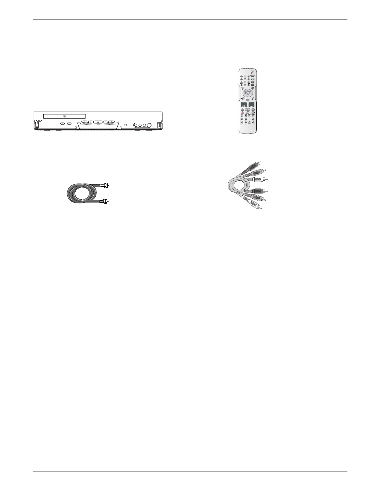
Unpack the Box
Your DVD recorder came with the following items:
CLEAR
DVD recorder Remote control
RF Coaxial cable
and batteries
1 set of audio video cables
Graphics contained within this publication are for representation only.
3
Chapter 1: Connections and Setup
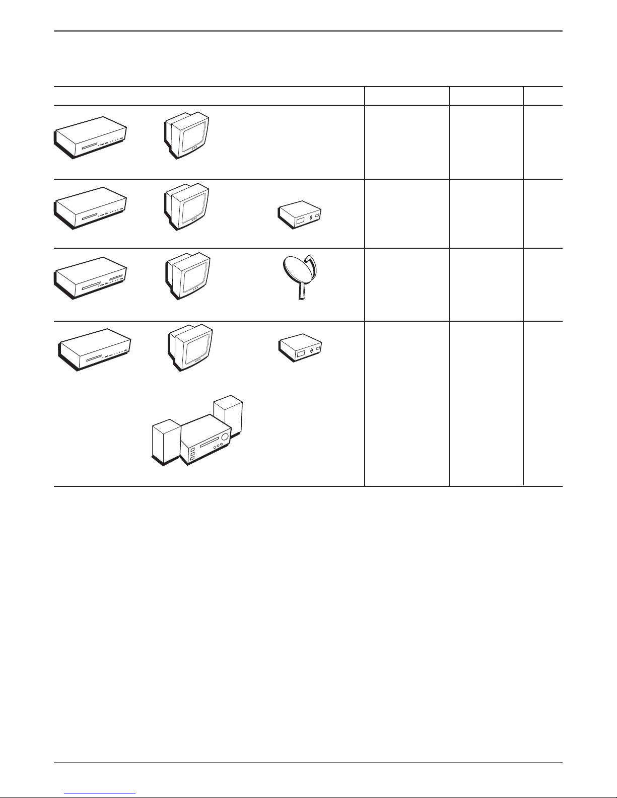
Choose Your Connection
There are several ways to connect your DVD recorder. Please use the following chart to determine which connection is best for you. Turn to the
appropriate page for specifi c instructions.
Components Cables Needed Connection Go to
• Coaxial
E
S
U
A
P
/
Y
A
L
P
WD
F
EV
R
P
O
T
S
D
OR
EC
R
E
OS
L
C
/
EN
OP
+
P
I
K
S
H+/
C
KIP-
S
/
HC
T
U
NP
I
• Audio/video
• S-Video
• Component Video
• HDMI
TV
page 8
TVDVD Recorder
E
S
U
A
/P
Y
A
L
P
D
W
F
V
E
R
STOP
D
COR
E
R
E
LOS
/C
EN
P
O
P+
I
K
S
+/
CH
PI
SK
/
-
CH
UT
P
N
I
DVD Recorder
E
US
A
/P
AY
L
P
WD
F
EV
R
P
STO
D
OR
C
E
R
SE
LO
/C
OPEN
+
IP
SK
CH+/
KIP-
/S
H
C
T
U
INP
DVD Recorder
AU
/P
LAY
P
D
FW
REV
P
TO
S
D
OR
REC
SE
CLO
OPEN/
+
/SKIP
CH+
SKIPH-/
C
INPUT
DVD Recorder
• Coaxial
• Audio/video
• S-Video
TV + cable
box
page 10
• Component Video
TV
Cable Box
• HDMI
• Coaxial
• Audio/video
• S-Video
• Component Video
TV
Satellite Receiver
• HDMI
• Coaxial
E
S
Cable Box
TV
• Audio/video
• S-Video
• Digital Audio
•Component Video
• HDMI
TV +
satellite
receiver
TV + cable
box + audio
receiver
page 12
page 14
Audio Receiver
4
Graphics contained within this publication are for representation only.
To achieve enhanced picture
quality, use an S-Video cable,
component video cables, or an
HDMI cable to connect your DVD
recorder to your TV if your TV has
corresponding jacks available.
Chapter 1: Connections and Setup
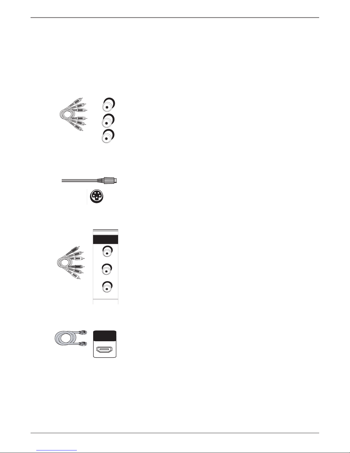
Explanation of Input Jacks and Cables
This section describes the jacks and cables you can use to make connections. Some cables are supplied with your product or you can purchase other cables
by calling
1-800-338-0376, order online at www.rca.com, or go to your local electronics store). There are several ways to connect your DVD recorder to your TV
depending upon the cables you have and the jacks that are on the back of your TV.
Different jacks and cables provide a different level of performance. It’s important to remember, we’re talking about degrees of picture improvement for
comparison. If your TV has Component jacks (Y, Pb, Pr), S-VIDEO, and composite video (often color-coded yellow); Component (Y, Pb, Pr), would be
considered excellent, S-Video would be very good, and the composite video jack (yellow) would be considered good.
Component Video (Y, Pb, Pr) Jacks and Cables
Y
Pb
Pr
S
The Y, Pb, Pr jacks provide optimum picture quality because the video is separated into three signals
(two signals are dedicated to the color portion of the image, and the other signal is dedicated to the
black and white part of the image).
To ensure maximum picture quality, use three video-grade cables (not supplied) for the connection.
You can purchase bundled component video cables that are color-coded to match the Y, Pb, Pr jacks
(red, green, and blue). Component Video Input jacks are usually found on high-end TVs, such as
HDTVs; multimedia monitors; and some of the “fl at” LCD and Plasma TVs or monitors.
Notes:
Also, remember to connect the left and right audio cables because the Y, Pb, Pr
jacks and cables carry only the picture signal, not the sound.
S-Video Jacks and Cables
The S-Video (separate video) jack provides better picture quality than a composite video jack
(sometimes labeled VIDEO and color-coded yellow on TVs) because S-Video keeps the color part of
the picture separate from the black and white part of the picture. If your TV has an S-VIDEO jack,
connect the DVD recorder to the TV with an S-Video cable for a better quality picture.
Note: Remember to connect the left and right audio cables because the S-Video
cable carries only the picture signal, not the sound.
AV1 IN
VIDEO IN
L
R
IN
HDMI OUT
Audio/Video Jacks and Cables (RCA-type)
Video
The basic Video jack (usually color-coded yellow) is also referred to as composite video. Composite
video doesn’t keep color information separated (like S-Video), but it’s better than the video quality
you get from an RF coaxial cable (the type used to connect a cable signal or off-air antenna).
Audio
These jacks are used to send the audio from the disc you’re playing in the DVD recorder to the TV.
The audio jacks and cables (supplied) are often color-coded (red for right audio, and white for left
audio). You must connect audio cables to the AUDIO L and R jacks on the DVD recorder and the
corresponding Audio Input Jacks on the TV no matter which Video jack you connect (VIDEO;
S-VIDEO; Y, Pb, Pr).
Note: If your TV has only one input for audio (mono), connect it to the left (white)
audio jack on the DVD recorder and don’t connect the right (red) audio part of the
cable.
HDMI™ OUTPUT (High-Defi nition Multimedia Interface)
Provides an uncompressed digital interface that carries both video and audio data to your TV by way
of an integrated mini-plug cable (HDMI cable not supplied). When connected to a compatible high
defi nition digital TV, the DVD recorder will convert standard defi nition signals to higher resolution
(high defi nition) signals.
Note: If your HDTV set has a DVI input and is HDCP (High Defi nition Copy
Protection) compatible, you can connect your recorder to the TV using an optional
HDMI cable and HDMI/DVI adapter. Remember to connect the left and right audio
cables because the DVI cable carries only the picture signal, not the sound.
Graphics contained within this publication are for representation only.
5

Chapter 1: Connections and Setup
OUT
COMPONENT
VIDEO OUT
IN
ANTENNA
/CABLE
COAXIAL OUT
HDMI OUT
S-VIDEO OUT
Y
Pb
Pr
OUTPUT
VIDEO
AUDIO
AV1 IN
VIDEO IN
S-VIDEO IN
L
R
L
AUDIO IN
R
L
R
Back of the DVD Recorder
The back of your recorder might look a little overwhelming at fi rst. This section explains what goes where and why. There are two sets of jacks on the back
of your DVD recorder—INPUT jacks and OUTPUT jacks.
Each jack is explained individually below, but the basic idea is about sending and receiving information to be played on or through your DVD recorder
and displaying that information on your TV screen.
INPUT
The cables connected to the INPUT jacks bring pictures and sound INTO the DVD recorder, such as the cable signal (programming) from the
cable company or satellite programming from a satellite receiver.
OUTPUT
the screen. The correct cables must be connected to the DVD recorder’s Output jacks and the corresponding Input Jacks on the TV so you can see the
program on the TV. You must also tune the TV to the correct channel, called a Video Input Channel (for details, go to page 20).
Explanation of Jacks (from left to right)
ANTENNA /CABLE IN –
programming from the source to the DVD recorder.
ANTENNA/CABLE OUT –
connect this cable so that your TV receives programming even when the DVD recorder is turned off.
HDMI OUT – If your TV has an HDMI jack, connects to your TV for high-defi nition video signal. Also provides 2-channel audio signal when the audio
output is set to PCM. See page 34. Press the HDMI button on the remote control to toggle the available resolutions.
COAXIAL OUT (Digital Coaxial) – Connects to an audio receiver or decoder using a digital coaxial connection.
S-VIDEO
recorder to achieve better picture quality than standard video (the yellow jack).
COMPONENT VIDEO OUT (Y, Pb, Pr) –
through these Output jacks provide the highest resolution because the video signal is divided into 3 separate parts (cables not supplied with DVD
recorder). As with VIDEO and S-VIDEO, COMPONENT VIDEO (Y, Pb, Pr) only carries the picture signal so you need to connect the audio cables so
you’ll hear the sound. If your TV has COMPONENT INPUT jacks, use three video grade cables to connect the DVD recorder to these jacks on the TV
to get the best picture quality.
OUTPUT –
through the TV’s speakers.
VIDEO: Color coded yellow, the video cable you use with this jack provides better quality than an RF coaxial cable but isn’t as good as S-Video.
AV1 IN/AUDIO IN –
front of the DVD recorder for temporarily connecting components such as a camcorder or a video game unit.
The cables connected to the OUTPUT jacks are sending pictures and sound from the DVD recorder OUT TO your TV so you can see it on
Connect an RF coaxial cable from an off-air antenna, cable box, or cable outlet to this jack. The cable is sending the
Connect an RF coaxial cable (provided) to this jack and to the Cable/Antenna Input jack on your TV. It is important to
OUT –
If your TV has an S-Video jack, connect an S-Video cable to the TV’s S-VIDEO jack and to this S-VIDEO OUT jack on the DVD
Some high-end TVs and monitors have Component Video Input jacks. The cables that send the video signal
These jacks send the content (audio and video) from your DVD recorder OUT to the TV so you can see it on the TV screen and hear it
AUDIO L (left): Color coded white, connect corresponding audio cable to TV’s Audio Left Input jack.
AUDIO R (right): Color coded red, connect corresponding audio cable to TV’s Audio Right Input jack.
These jacks receive audio from a compatible component, such as a satellite receiver. Another set of Input Jacks (INPUT 2) are on the
VIDEO: Color coded yellow, the video cable you use with this jack provides better quality than an RF coaxial cable but isn’t as good as S-Video.
Connect corresponding video cable to the output jack of a compatible component, such as a satellite receiver or cable box.
AUDIO L (left): Color coded white, connect corresponding audio cable to the output jack of a compatible component, such as a satellite receiver
or cable box.
AUDIO R (right): Color coded red, connect corresponding audio cable to the output jack of a compatible component, such as a satellite receiver
or cable box.
S-VIDEO IN: If your satellite receiver or cable box has an S-VIDEO output jack, connect the S-Video cable to this jack because it provides better
picture quality than standard video (the yellow jack).
6
Graphics contained within this publication are for representation only.
continues on next page…

Chapter 1: Connections and Setup
Front of the DVD Recorder
STANDBY/ON –
CH- (channel down) –
CH+ (channel up) –
OPEN/CLOSE –
STOP –
PLAY/PAUSE –
INPUT –
Input Channel is the “channel” to which you tune the DVD recorder so you can see the picture and hear the sound that’s coming from the component
that is connected to the DVD recorder’s INPUT jacks. For example, if you connected your camcorder to the Audio and Video Input jacks on the front of
the DVD recorder, you would press the INPUT button until AV 2 appears.
DVD RECORD –
Turns the DVD recorder on and off.
Goes to the previous channel in the channel list when you’re watching TV.
Goes to the next channel in the channel list when you’re watching TV.
Opens and closes the disc tray.
Stops playback and/or recording.
Starts playback of a disc. Pauses recording or playback.
Just like a TV has Video Input Channels (page 20), the DVD recorder has one Video Input Channel for each set of INPUT jacks. The Video
Records content to a DVD disc.
Front Input Jacks:
DV IN – This jack is provided when you’re connecting a DV camcorder through a IEEE 1394 Firewire connection. The DV connection can also control the DV playback
using the DVD recorder’s remote.
INPUT 2: Audio/Video jacks – These Input jacks are provided for convenience when you’re connecting a temporary component, such as a camcorder.
S-VIDEO – If a component you’re connecting, such as a camcorder, has an S-Video Output jack connect it to this jack for picture quality that is better than regular video
(yellow). Remember, you still have to connect audio cables to hear sound.
Graphics contained within this publication are for representation only.
7
Chapter 1: Connections and Setup
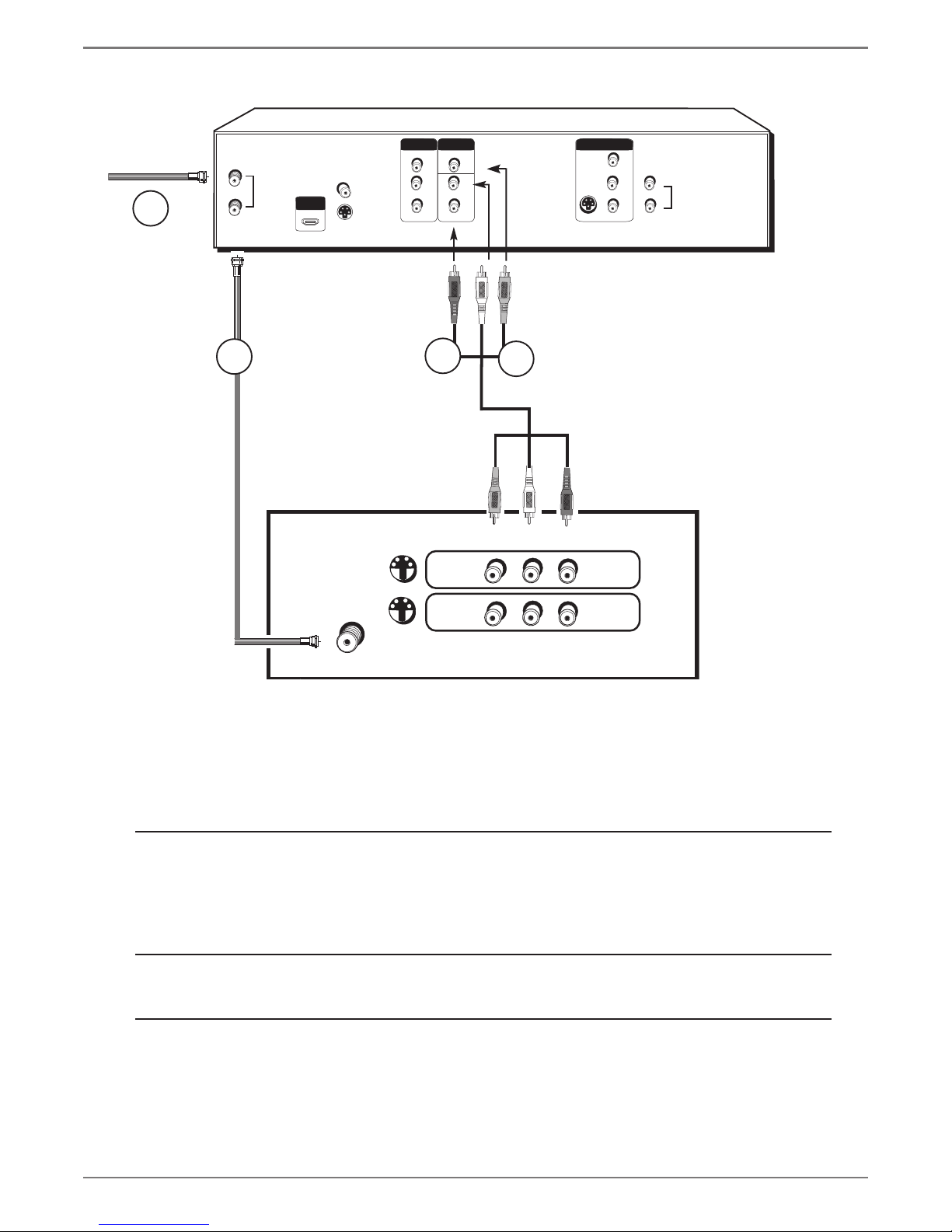
DVD recorder + TV
In from cable
or antenna
1
DVD
recorder
IN
ANTENNA
/CABLE
OUT
HDMI OUT
COAXIAL OUT
S-VIDEO OUT
COMPONENT
VIDEO OUT
Y
Pb
Pr
OUTPUT
AUDIO
VIDEO
AV1 IN
VIDEO IN
S-VIDEO IN
L
R
L
AUDIO IN
R
L
R
2a
S-VIDEO
2c
2b
VIDEO L
R
INPUT1
S-VIDEO
CABLE/ANTENNA
INPUT2
TV
The back of your TV might look different
than the one pictured here.
Details about the different kinds of cables used to connect your DVD recorder are on page 4.
To watch one program while you
record another:
To play a disc or tape:
If you need help fi nding your TV’s various Video Input Channels, go to page 20.
8
Graphics contained within this publication are for representation only.
Tune the TV to its Input 1 channel or Vid 1 channel
Tune the DVD recorder to the channel you want to record, and press RECORD.
Use the buttons on the TV (or the TV’s remote control*) to tune the TV to the channel
you want to watch. For example, change the channel on the TV to channel 8 to watch a
program on channel 8.
Tune the TV to its Input 1 channel or Vid 1 channel.

RF Coaxial cable
Red
Yellow
White
Audio video cables are
usually color-coded red,
white, and yellow.
Chapter 1: Connections and Setup
Connection: DVD recorder + TV
1.
Connect the signal (cable or antenna):
Note: Depending upon how you currently have your TV connected, you’ll have to
disconnect the cable from your TV’s Antenna Input jack (sometimes labeled CABLE/
ANTENNA) or your VCR’s Input jack before you connect the cable as explained below.
Cable service:
cable to the ANTENNA/CABLE INPUT jack on the DVD recorder.
Note: If you have a cable box, go to page 10 for connection instructions.
Off-air antenna:
coaxial cable to the ANTENNA/CABLE INPUT jack on the DVD recorder.
2. Connect the DVD recorder to the TV
You need to connect cables from the DVD recorder’s OUTPUT jacks to the TV’s INPUT jacks in order to
see the content from the DVD recorder.
2a. Use the RF Coaxial cable that was packed with your DVD recorder, and connect one end to
the ANTENNA/CABLE OUTPUT jack on the DVD recorder. Connect the other end to the
Cable/Antenna Input jack on the back of your TV (sometimes labeled CABLE/ANTENNA). It is
important to make this connection so you can watch cable or antenna programs when the DVD
recorder is off.
2b.
Connect the audio cables.
A set of audio/video cables was packed with your DVD recorder. Connect the audio cables to
the AUDIO OUTPUT L (left – white) and R (right – red) jacks on the back of your DVD
recorder, and to the corresponding Audio Input jacks on your TV (sometimes labeled AUDIO IN
L and R).
2c.
Connect the video cable. The cables you use for the video determine the quality of the picture
you’ll see on your TV when you’re playing DVDs. For more information about cables and signal
quality, go to page 5. Connect the video cable (yellow) to the VIDEO OUTPUT jack on the back
of your DVD recorder, and to the Video Input jack on your TV (sometimes labeled VIDEO IN).
S-VIDEO (not shown) If your TV has an S-Video jack, use an optional S-Video cable. Connect
one end of the S-Video cable to the S-VIDEO IN jack on the back of the TV and the other end to
the S-VIDEO OUT jack on the back of the DVD recorder.
COMPONENT VIDEO Y, Pb, Pr (not shown)
Pr), you can achieve even greater picture quality (DVD playback only) by connecting the DVD
recorder to the TV using these jacks (COMPONENT VIDEO OUT, Y, Pb, Pr on the DVD
recorder). For more explanation, go to page 5. Component Video cables not supplied with the
DVD recorder.
HDMI (not shown) If you TV has an HDMI Input Jack, you can achieve optimum picture
quality. Connect one end of the HDMI cable to the HDMI jack on the back of the TV and the
other end to the HDMI jack on the back of the DVD recorder. Press the HDMI button on the
remote to toggle the available progressive scan and interlace modes.
Notes:
If your TV is capable of progressive scan, connect the DVD recorder to the TV using the
COMPONENT VIDEO OUT jacks, and press the HDMI button on the remote to toggle
between progressive scan and interlace. Please note that the component video output
mode will remain at 480p even though the HDMI video output mode is 480p/720p/1080i,
which is displayed on the front of the unit.
3.
Plug the power cord into an AC outlet.
If you have cable service via a cable that comes out of the wall, connect the end of that
If you use an off-air antenna to get TV programming, connect the antenna’s RF
If your TV has Component Input Jacks (Y, Pb,
Graphics contained within this publication are for representation only.
Go to page 17
9
Chapter 1: Connections and Setup
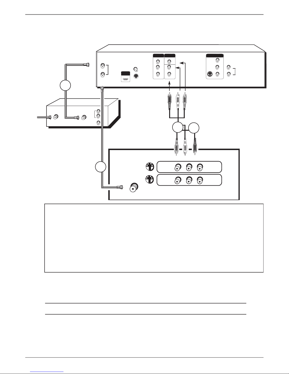
DVD recorder + TV+ Basic Cable Box
The back of
your TV
and/or Cable
Box might
look different
than the ones
pictured here.
CABLE IN CABLE OU T
DVD
recorder
1a
IN
ANTENNA
/CABLE
OUT
AUDI O
L
R
VIDEO
HDMI OUT
COAXIAL OUT
S-VIDEO OUT
COMPONENT
VIDEO OUT
Y
Pb
Pr
OUTPUT
AUDIO
VIDEO
R
AV1 IN
VIDEO IN
S-VIDEO IN
L
R
L
AUDIO IN
R
L
2c
2b
Cable Box
S-VIDEO
2a
VIDEO L
INPUT1
S-VIDEO
TV
CABLE/ANTENNA
INPUT2
Notes about cable boxes:
The connection diagram shown above refl ects a basic setup. Since there are many different cable companies and types of
cables boxes, your cable box may come with a different recommended connection diagram. Normally, ANALOG cable boxes
are used so that the cable company can scramble the signal for premium channel programming (like movie channels). The
cable box will descramble the signal if you are a premium channel subscriber. In some cases, your cable company may not
scramble the signal for basic channels and the signal could be passed through the cable box so that you could receive the
signal with the DVD recorder.
There are also DIGITAL cable boxes that are relatively new and are used with digital cable service. Even with digital cable
service, analog signals are often carried on the same cable.
Using the connection diagram above, you won’t be able to watch one program while recording another program. This may
be possible with a more sophisticated setup, using an optional signal splitter and A-B switch. We suggest you contact your
cable company for help in recommending the best setup for your situation.
R
If you connect your components as described, you must access different Video Input Channels on your TV to see
programming. If you don’t know how to access Video Input Channels on your TV, go to page 20 for help. A general
explanation, based on the connection shown above, follows:
To play a disc:
Tune the TV to its Input 1 channel or Vid 1 channel.
If you need help fi nding your TV’s various Video Input Channels, go to page 20.
10
Graphics contained within this publication are for representation only.

RF Coaxial cable
Red
Yellow
White
Audio video cables are
usually color-coded red,
white, and yellow.
Chapter 1: Connections and Setup
Connection: DVD recorder + TV + Basic Cable Box
1. Connect the cable box signal.
Note: Before you connect the DVD recorder, you’ll need to disconnect some of the cables
fi rst in order to reconnect them.
1a.
Connect the RF coaxial cable that is connected to the cable box’s Output jack (sometimes labeled
CABLE OUT) to the ANTENNA/CABLE INPUT jack on the back of the DVD recorder.
1b. If your cable box has audio/video output jacks, connect the audio cables to the Audio Output L
(left – white) and R (right – red) jacks on the back of your cable box, and to the corresponding
INPUT AUDIO jacks on your DVD recorder. Then connect the video cable (yellow) to the Video
Out jack on the back of your cable box, and to the INPUT VIDEO jack on your TV.
2. Connect the DVD recorder to the TV
You need to connect cables from the DVD recorder’s OUTPUT jacks to the TV’s INPUT jacks in
order to see the content from the DVD recorder (whether it’s a TV program or a disc you’re playing).
2a.
Use the RF coaxial cable that was packed with your DVD recorder, and connect one end to
the ANTENNA/CABLE OUTPUT jack on the DVD recorder. Connect the other end to the
Cable/Antenna Input jack on the back of your TV (sometimes labeled CABLE/ANTENNA). It is
important to make this connection so you can watch cable box programs when the DVD recorder
is off.
2b.
Connect the audio cables.
A set of audio/video cables was packed with your DVD recorder. Connect the audio cables to the
AUDIO OUTPUT L (left – white) and R (right – red) jacks on the back of your DVD recorder,
and to the corresponding Audio Input jacks on your TV (sometimes labeled AUDIO IN L and R).
2c.
Connect the video cable. The cables you use for the video determine the quality of the picture
you’ll see on your TV when you’re playing DVDs. For more information about cables and signal
quality, go to page 5.
Connect the video cable (yellow) to the VIDEO OUTPUT jack on the back of your DVD
recorder, and to the Video Input jack on your TV (sometimes labeled VIDEO IN).
S-VIDEO
cable to the S-VIDEO IN jack on the back of the TV and the other end to the S-VIDEO OUT
jack on the back of the DVD recorder.
COMPONENT VIDEO Y, Pb, Pr (not shown)
Pr), you can achieve even greater picture quality (DVD playback only) by connecting the DVD
recorder to the TV using these jacks (COMPONENT VIDEO OUT, Y, Pb, Pr on the DVD
recorder). For more explanation, go to page 5. Component Video cables not supplied with the
DVD recorder.
HDMI (not shown) If you TV has an HDMI Input Jack, you can achieve optimum picture
quality. Connect one end of the HDMI cable to the HDMI jack on the back of the TV and the
other end to the HDMI jack on the back of the DVD recorder. Press the HDMI button on the
remote to toggle the available progressive scan and interlace modes.
Notes:
If your TV is capable of progressive scan, connect the DVD recorder to the TV using the
COMPONENT VIDEO OUT jacks, and press the HDMI button on the remote to toggle
between progressive scan and interlace. Please note that the component video output
mode will remain at 480p even though the HDMI video output mode is 480p/720p/1080i,
which is displayed on the front of the unit.
3. Plug the power cord into an AC outlet.
(not shown) If your TV has an S-VIDEO jack, connect one end of an optional S-Video
If your TV has Component Input Jacks (Y, Pb,
Graphics contained within this publication are for representation only.
Go to page 17
11
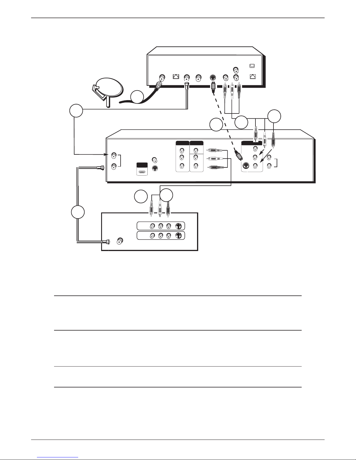
Chapter 1: Connections and Setup
DVD recorder + TV+ Satellite Receiver
The back of your
satellite receiver
might look
different than
the one pictured
here.
DVD recorder
2a
3a
SATELLITE
DISH
ANTENNA
IN
OUT
TV
CABLE/ANTENNA
ANTENNA
/CABLE
1
HDMI OUT
3c
INPUT1
INPUT2
COAXIAL OUT
S-VIDEO OUT
VIDEO L
3b
AUDIO OUT
DIGITAL OUT
LOW SPEED
DA TA OUT TO TV IN FROM ANT SA TELLITE IN
S-VIDE O
R
VIDE O
PHONE JACK
L
2b
2d
COMPONENT
OUTPUT
VIDEO OUT
Y
Pb
Pr
R
S-VIDEO
AUDIO
VIDEO
L
R
2c
AV1 IN
VIDEO IN
L
R
S-VIDEO IN
Important
You can’t watch one satellite
program and record another
satellite program at the same time.
L
AUDIO IN
R
The back of your TV might look different
than the one pictured here.
Details about the different kinds of cables used to connect your DVD recorder are on page 5.
To watch TV (satellite
programming) with the DVD
Recorder turned on:
Tune the TV to its Input 1 channel or Vid 1 channel.
Tune the DVD recorder to the INPUT 1 channel (press the INPUT button on the remote).
Tune the satellite receiver to the channel you want to watch.
To watch TV (satellite
programming) with the
DVD recorder turned off:
To play a disc
If you need help fi nding your TV’s various Video Input Channels, go to page 20.
Tune the TV to its CABLE/ANTENNA INPUT channel (usually channel 2, 3, or 4).
Tune the satellite receiver to the channel you want to watch.
Tune the TV to its Input 1 channel or Vid 1 channel.
12
Graphics contained within this publication are for representation only.
 Loading...