

RCA D52W17YX1, D56W20YX1, D52W19YX1, D52W15YX1, D40W15YX1 User Manual
...
HDTV Monitor
User's G ude
Changing Entertainment. _in.
ImportaHt IHformatioa
I
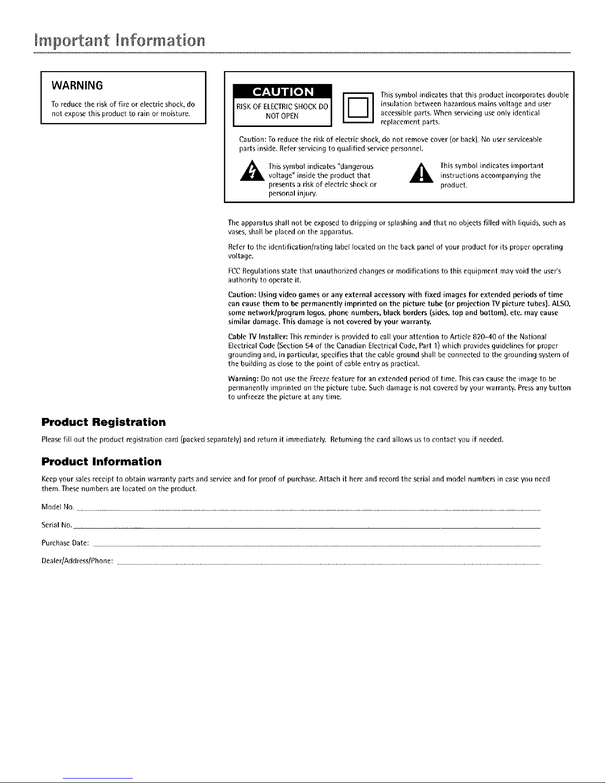
WARNING
To reducethe riskof fire or electric shock, do
not expose this product to rain or moisture.
I
Thissymbol indicates that this product incorporates double
insulation between hazardous mains voltage and user
accessibleparts. Whenservicing useonly identical
replacement parts.
Caution: To reduce the risk of electric shock,do not remove cover (or back). No user serviceable
parts inside. Referservicing to qualified service personnel.
A his symbol indicates "dangerous
voltage" inside the product that
presentsa risk of electricshock or
personal injur%
_. his symbol indicates importantinstructions accompanying the
product.
Theapparatus shall not beexposedtodripping or splashing and that no objects filled with liquids, such as
vases,shallbe placed on the apparatus.
Refer to the identification/rating label located on the backpanel of your product for its proper operating
voltage.
FCCRegulations state that unauthorized changes or modifications to this equipment mayvoid the user's
authority to operate it.
Caution: Using video games or any external aecessowwith fixed images for extended periods of time
can causethem to be permanently imprinted on the picture tube (or projection TV picture tubes). ALSO,
some network/program loges, phone numbers,black borders (sides,top and bottom), etc. may cause
similar damage. This damage is not coveredby your warranty.
Cable "!VInstaller: Thisreminder is provided to call your attention to Article 820-40 of the National
Electrical Code(Section 54 of the Canadian Electrical Code, Part I) whichprovides guidelines for proper
grounding and, in particular, specifies that the cable ground shall be connected to the grounding system of
the building as closeto the point of cable entry as practical.
Warning: Do not use the Freeze feature for an extended period of time. This can cause the image to be
permanently imprinted on the picture tube. Such damage is not covered by your warranty Press any button
to unfreeze the picture at any time.
Product Registration
Pleasefill out tile product registration card (packedseparately) and return it immediately. Returningthe card allows us to contact you if needed.
Product Information
Keepyour salesreceipt to obtain warranty parts and serviceand for proof of purchase. Attach it here and record the serial and model numbers in caseyou need
them. Thesenumbers are located on the product.
Model No.
Serial NO.
Purchase Date:
Dealer/Address/Phone:
ImportaHt IHformatio '
IMPORTANT SAFETY INSTRUCTIONS
1. Read these instructions.
2. Keep these instructions.
3. Heed all warnings.
4. Follow all instructions.
5. Do not use this apparatus near water.
6. Clean only with dry cloth.
7. Do not block any ventilation openings. Install in accordance with the manufacturer's instructions.
8. Do not install near any heat sources such as radiators, heat registers, stoves, or other apparatus (including amplifiers) that produce heat.
9. Do not defeat the safety purpose of the polarized or grounding-type plug. A polarized plug has two blades with one wider than the other. A
grounding type plug has two blades and a third grounding prong. The wide blade or the third prong is provided for your safety. If the provided
plug does not fit into your outlet, consult an electrician for replacement of the obsolete outlet.
10. Protect the power cord from being walked on or pinched particularly at plugs, convenience receptacles, and the point where they exit from the
apparatus.
11. Only use attachments/accessories specified by the manufacturer.
e9
12. Use only with the cart, stand, tripod, bracket, or table specified by the manufacturer, or sold with the apparatus. When a cart is
used, use caution when moving the eartlapparatus combination to avoid injury from tip-over.
13. Unplug this apparatus during lightning storms or when unused for long periods of time.
14. Refer all servicing to qualified service personnel. Servicing is required when the apparatus has been damaged in any way, such as power-supply
cord or plug is damaged, liquid has been spilled or objects have fallen into the apparatus, the apparatus has been exposed to rain or moisture, does
not operate normally, or has been dropped.
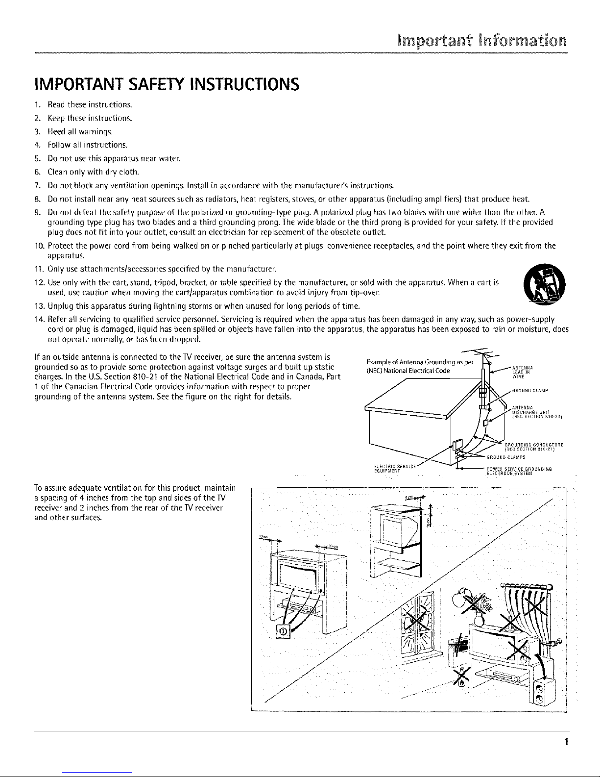
If an outside antenna is connected to the IV receiver, be sure the antenna system is
grounded so as to provide some protection against voltage surges and built up static
charges. In the U.S. Section 810-21 of the National Electrical Code and in Canada, Part
1 of the Canadian Electrical Code provides information with respect to proper
grounding of the antenna system. See the figure on the right for details.
Example of Antenna Grouodin
(NEC) National Electrical Code
Toassure adequate ventilation for this product, maintain
a spacing of 4 inches from the top and sides of the IV
receiver and 2 inches from the rear of the IV receiver
and other surfaces.
/
/
/
./-
J
/
/
/
J
/
J
.1"
/-
..--
/
r
Key Features Overview
Your IV is equipped with features that will add to your IV viewing experience. The following information
summarizes a few of these features. Chapter 3 provides more information about the rest of the Iv's features and
how to use them.
DVI-HDIV L/MOlIO
PIPexample
POPexample
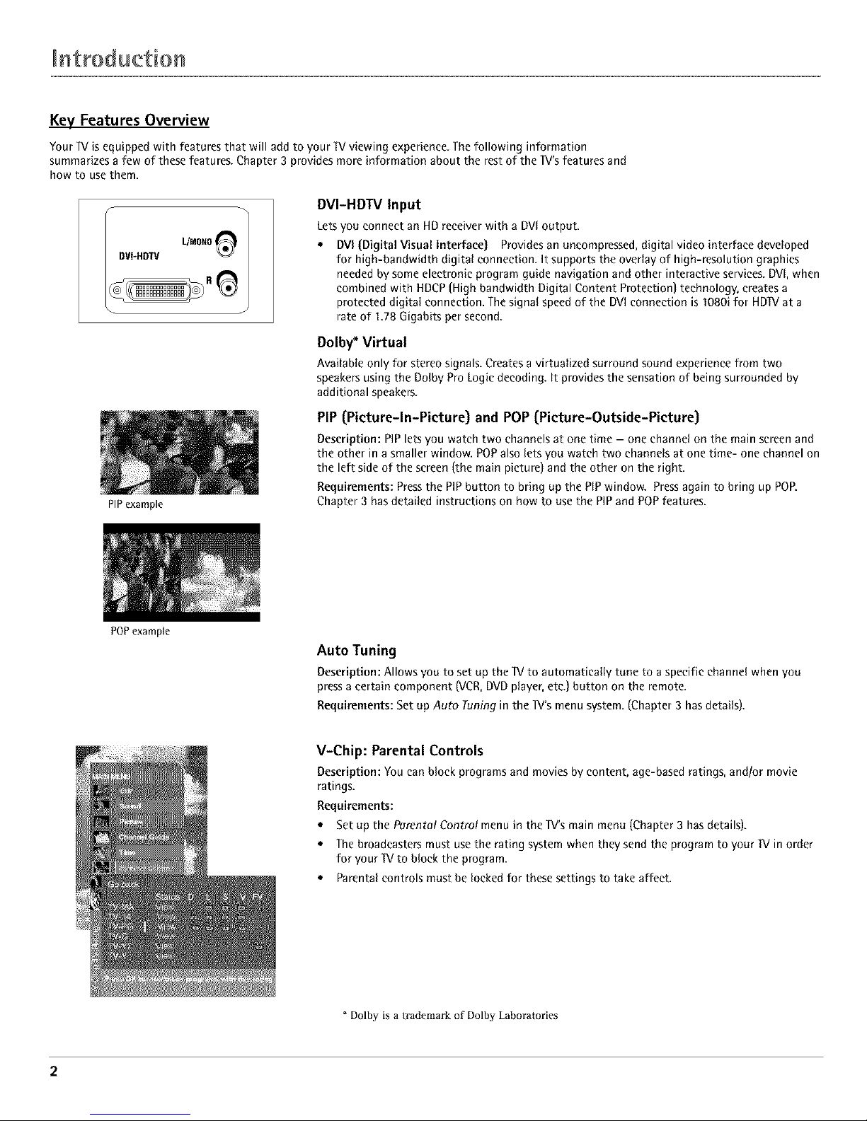
DVI-HDW Input
Lets you connect an HD receiver with a DVl output.
• DVl (Digital Visual Interface) Provides an uneompressed, digital video interface developed
for high-bandwidth digital connection. It supports the overlay of high-resolution graphics
needed by some electronic program guide navigation and other interactive services. DVl, when
combined with HDCP (High bandwidth Digital Content Protection) technology, creates a
protected digital connection. The signal speed of the DVl connection is 1080i for HDIV at a
rate of 1.78 Gigabits per second.
Dolby _ Virtual
Available only for stereo signals. Creates a virtualized surround sound experience from two
speakers using the Dolby Pro Logic decoding. It provides the sensation of being surrounded by
additional speakers.
PIP (Picture-ln-Picture) and POP (Picture-Outside-Picture)
Description: PIP lets you watch two channels at one time - one channel on the main screen and
the other in a smaller window. POPalso lets you watch two channels at one time- one channel on
the left side of the screen (the main picture) and the other on the right.
Requirements: Press the PIP button to bring up the PiP window. Pressagain to bring up POR
Chapter 3 has detailed instructions on how to use the PIP and POP features.
Auto Tuning
Description:Allows you to set up the IV to automatically tune to a specific channel when you
pressa certain component (VCR,DVDplayer,etc.) button on the remote.
Requirements: Set up Auto runin9 in the Iv's menu system. (Chapter 3 has details).
V-Chip: Parental Controls
Description:You can block programsand movies by content, age-basedratings, and/or movie
ratings.
Requirements:
• Set up the Parental Control menu in the 1V's main menu (Chapter 3 has details).
• The broadcasters must use the rating system when they send the program to your IV in order
for your IV to block the program.
• Parental controls must be locked for these settings to take affect.
Dolby is a trademark of Dolby Laboratories
2
TaWc of ConteHts
IMPORTANT SAFETY INSTRUCTIONS ................ 1
Introduction
Key Features Overview ............................................... 2
DVI-HDTV Input ............................................. 2
Dolby* Virtual ................................................... 2
PIP (Picture-In-Picture) and POP
(Picture-Outside-Picture) ................................ 2
Auto Tuning ...................................................... 2
V-Chip: Parental Controls ................................. 2
Chapter 1: Connections and Setup
Things to Consider Before You Connect .................. 4
Protect Against Power Surges .......................... 4
Protect Components from Overheating .......... 4
Position Cables Properly to Avoid Audio
Interference ..................................................... 4
Important Stand and Base Safety
Information ..................................................... 4
Use Indirect Light .............................................. 4
Cables Needed to Connect Components to
Your TV ............................................................ 4
Choose Your Connection ............................................ 5
TV + HD Receiver + VCR + DVD Player .................... 6
TV + Satellite Receiver + VCR .................................. 7
TV + OVO + VCR ......................................................... 8
IV+ AN Receiver or Speakers .................................. 9
Explanation of Jacks ................................................ 10
The Front of Your IV ............................................... 11
Front Inputs ..................................................... 11
Front Panel Buttons ........................................ 11
Plug in theTV ........................................................... 11
Put batteries in the remote ..................................... 11
How to Use the Remote Control to Complete the
Initial Setup ............................................................ 11
Turn on theTV .......................................................... 11
Complete the Initial Setup ...................................... 11
Set the Menu Language ................................. 12
Complete Auto Channel Search ..................... 12
Changing Lists and Labels .............................. 12
Auto Convergence .......................................... 12
Chapter 2: Using the Remote Control
The Buttons on the Remote Control ...................... 13
Using the INPUT Button ................................. 14
Programming the Remote to Operate Other
Components ............................................................ 14
Find Out If You Need to Program the
Remote .......................................................... 14
Programming the Remote .............................. 14
How to Use the Remote After You've
Programmed It .............................................. 15
Remote Control Codes ............................................. 15
Chapter 3: Using the TV's Features
Channel Banner ........................................................ 17
Why You Should Use the Autotuning Feature ...... 17
How to Set Up the Autotuning Feature ........ 17
Parental Controls and V-Chip ................................. 18
How V-Chip Works .......................................... 18
V-Chip TV Rating ............................................. 19
Blocking Specific Content Themes ................. 20
Viewing Specific Content Themes .................. 20
V-Chip Movie Rating Limit ............................. 20
V-Chip Unrated Program Block ...................... 21
Lock/Unlock Parental Controls ....................... 21
Front Panel Block ............................................ 21
PIP (Picture-in-Picture) and POP
(Picture-outside-Picture) Operation ................... 21
PIP and POP Buttons ....................................... 21
Chapter 4: Using the TV's Menu System
Sound Menu .............................................................. 22
Picture Menu ............................................................ 23
Channel Guide Menu ............................................... 23
Time Menu ................................................................ 24
Parental Control Menu ............................................ 24
PiP Menu ................................................................... 24
Setup Menu .............................................................. 24
Chapter 5: Other Information
Troubleshooting ........................................................ 26
Care and Cleaning .................................................... 27
Limited Warranty ..................................................... 28
Accessories ................................................................ 29
3
CoHnections Setup
Things to Consider Before You Connect
Protect Against Power Surges
• Connect all components before you plug any of their power cords into the wall outlet.
• Turn off the 1Vand/or component before you connect or disconnect any cables.
• Make sureall antennas and cables areproperly grounded. Referto the Important Safety Instructions on page 1.
Protect Components from Overheating
• Don't block ventilation holes on any of the components. Arrange the components so that air can circulate freely.
• Don't stack components.
• When you place components in a stand, make sure you allow adequate ventilation.
• If you connect an audio receiver or amplifier, place it on the top shelf so the heated air from it won't flow around
other components.
Position Cables Properly to Avoid Audio Interference
• Insert each cable firmly into the designated jack.
• If you place components above the IV, route all cables down the side of the back of the IV instead of straight
down the middle of the IV.
• If your antenna uses 3OO-ohm twin lead cables, do not coil the cables. Also, keep the twin lead cables away from
audio/video cables.
Important Stand and Base Safety Information
Choose the location for your IV carefully. Place the IV on a stand or base that is of adequate size and strength to
prevent the IV from being accidentally tipped over, pushed off, or pulled off. This could cause personal injury and/or
damage the IV. Refer to the Important Safety Instructions on page 1.
Use Indirect Light
Don't place the IV where sunlight or room lighting will be directed toward the screen.Usesoft or indirect lighting.
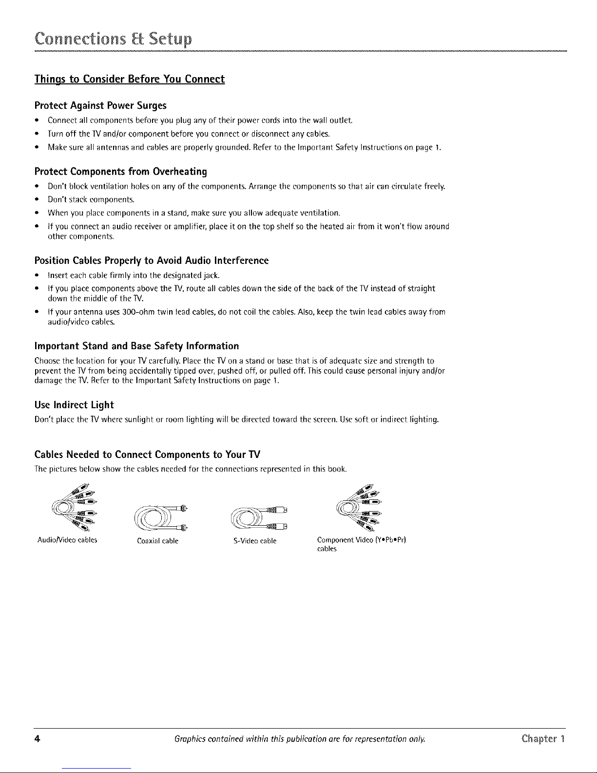
Cables Needed to Connect Components to Your IV
The pictures below show the cablesneededfor the connections representedin this book.
Audio/Video cables
Coaxial cable S-Video cable Component Video (Y,Pb-Pr)
cables
4 Graphics contained within this publication are for representation only Chapter 1

CoHneetions Setup
Choose Your Connection
There are several ways to connect your W, Please use the following chart to determine which connection is best for
you. Proceed to the appropriate page and connect your ]V.
Note:if youprefer,we conprovide you with thenameof on Authorized ServiceRepresentativewho wilyvisit your homefor e feeto
instoll your electronic entertoinment systemend toinstruct youin its operation.Fordetails obout thisservice,ceil 1-888-206_3359.
Components
_eeeWe_ oxlO
_o
Cables
Needed
Coaxial
Audio/video
Component video
Coaxial
Audio/video
S-Video
Coaxial
Audio/video
Component video
Connection
Title
TV + HD Receiver
+ DVD + VCR
TV + Satellite
Receiver+ VCR
TV + DVD+ VCR
Go to...
page 6
page 7
page 8
For general information on connecting an A/V receiver or speakers to your ]V, go to page 9,
Chapter 1 Graphics eonteined within this publicetion ere for representetion only. 5
CoNnections Setup
HD RECE
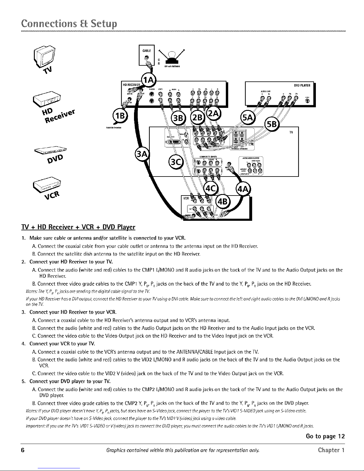
"IV + HD Receiver + VCR + DVD Player
1. Make sure cable or antenna and/or satellite is connected to your VCR.
A. Connect the coaxial cable from your cable outlet or antenna to the antenna input on the HD Receiver.
B.Connect the satellite dish antenna to the satellite input on the HD Receiver.
2. Connect your HD Receiver to your TV.
A. Connect the audio (white and red) cables to the CMP1 L/MONOand Raudio jacks on the back of the TVand to the Audio Output jacks on the
HDReceiver.
B.Connect three video grade cablesto the CMP1Y,PB,P,jacks on the back of the W and to the Y,PB,P,jacks on the HD Receiver.
Notes: Tile Y,,P_ P_jocks are sending the digital cable signal to the IV
If your HD Receiver has a DVI outpu t, connect the HD Receiver to your 1Vusing a DVI cab/e. Make sure to connect the left and Nght audio cables to the DVI L/MONO and Rjacks
onthePZ
3. Connect your HD Receiver to your VCR.
A. Connect a coaxial cable to the HDReceiver'santenna output and to VCR'santenna input.
B.Connect the audio (white and red)cablesto the Audio Output jacks on the HD Receiverand to the Audio Input jacks on the VCR.
C.Connect the video cable to the Video Output jack on the HDReceiverandto the Video Input jack on the VCR.
4. Connect your VCRto your TV.
A. Connect a coaxial cable to the VCR'santenna output and to the ANTENNA/CABLEInput jack on the lV.
B.Connect the audio (white and red]canes to the VlD2 L/MONOand Raudio jacks on the back of the W and to the Audio Output jacks on the
VCR.
C.Connect the video cable to the VID2 V (video) jack on the back of the W and to the Video Output jack on the VCR.
5. Connect your DVDplayer to your TV.
A. Connect the audio (white and red)cablesto the CMP2 L/MONOand Raudio jacks on the back of the W and to the Audio Output jacks on the
DVDplayer.
B.Connect three video grade cablesto the CMP2Y,PB,P,jacks on the back of the IV and to the Y,PB,PRjacks on the DVD player.
Notes:IfyourDVDplayerdoesn'thave Y,PB,PRjacks,but doeshaveanS-Videojack,connect tileplayertothe _s VID1S-VIDEOjackusingenS-Videocable.
If your DVD player doesn't have on S-Video jack, connect the plover to the ?V's VID1 V lvideo} jack using o video cable.
Irnporton e If you use the Iv's VID 1S-VIDEO or V(videoJjock to connect the DVD player, you must connect the audio cables to tt?e IV'S VID 1Z/MONO and Rjocks.
Go to page 12
6 Graphics contained within this publication are for representation only. Chapter 1
CoHneetions Setup
SATELLITE i
RECEIVER
TV
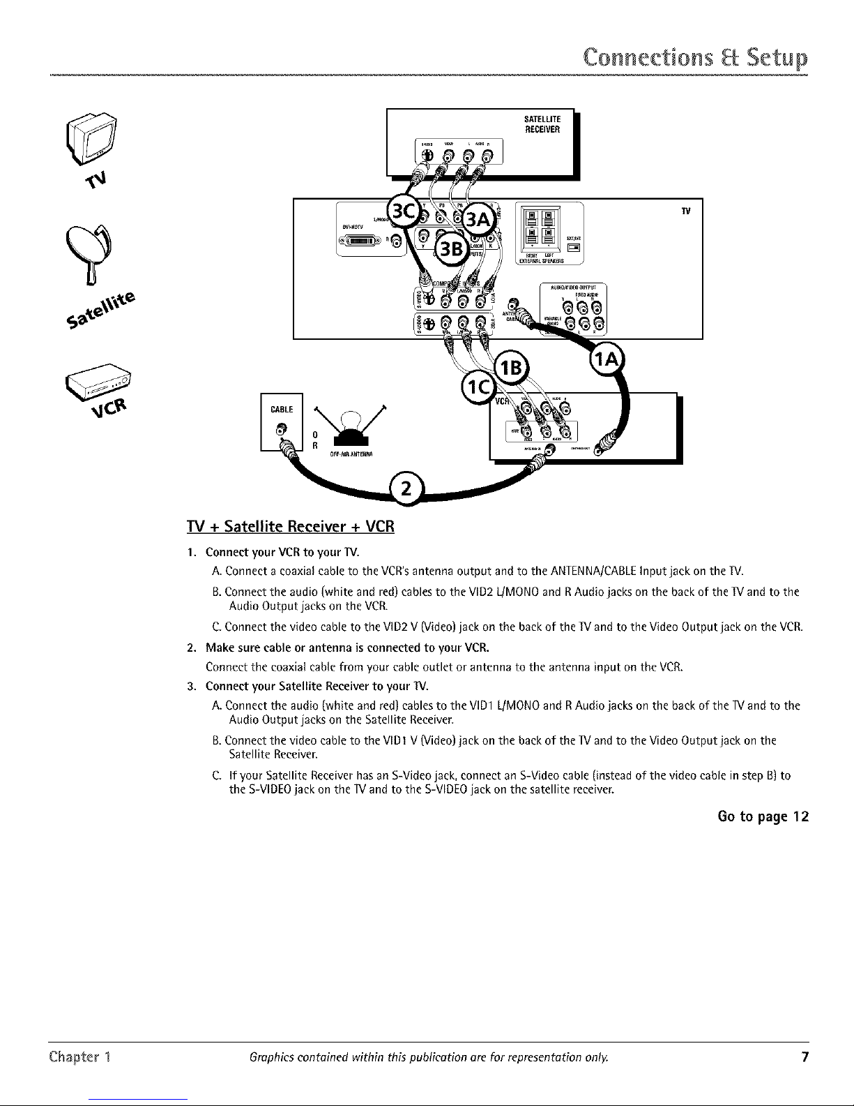
IV + Satellite Receiver + VCR
1. Connect your VCR to your IV.
A. Connect a coaxial cable to the VCR's antenna output and to the ANTENNA/CABLE Input jack on the TV,
B,Connect the audio (white and red) cables to the VlD2 L/MONO and R Audio jacks on the back of the W and to the
Audio Output jacks on the VCR.
C. Connect the video cable to the VID2 V (Video) jack on the back of the TV and to the Video Output jack on the VCR,
2. Make sure cable or antenna is connected to your VCR.
Connect the coaxial cable from your cable outlet or antenna to the antenna input on the VCR,
3. Connect your Satellite Receiver to your W.
A. Connect the audio (white and red) cables to the VID1 L/MONO and R Audio jacks on the back of the _V and to the
Audio Output jacks on the Satellite Receiver.
B.Connect the video cable to the VIDI V (Video) jack on the back of the W and to the Video Output jack on the
Satellite Receiver.
C. If your Satellite Receiver has an S-Video jack, connect an S-Video cable (instead of the video cable in step B) to
the S-VIDEO jack on the _V and to the S-VIDEO jack on the satellite receiver.
13oto page 12
Chapter 1 Graphics contained within this publication are for representation only. 7
CoHaections Setup
DVO Player
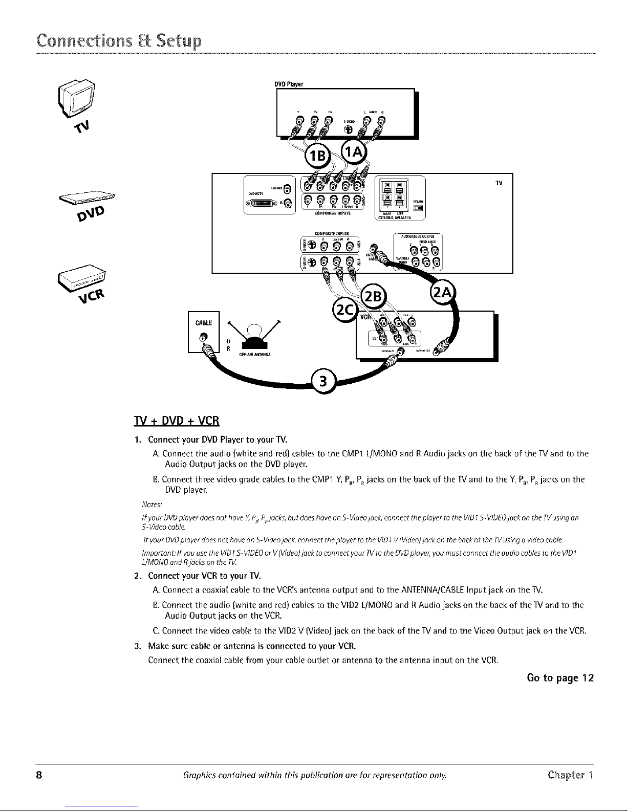
TV + DVD + VCR
1. Connect your DVD Player to your TV.
A. Connect the audio (white and red) cables to the CMP1 L/MONO and R Audio jacks on the back of the IV and to the
Audio Output jacks on the DVD player.
B.Connect three video grade canes to the CMP1 Y, P_, PRjacks on the back of the TV and to the Y, PB,PRjacks on the
DVD player.
Notes:
If your OVDplayerdoesnothove Y,P_ Pjacks, but doeshoveenS-Videojack, connect theplayer to the VIO1S-VIDEOjack on the W usingon
5-Video cable.
/f your OVOplayerdoesnot haveon S-Videojack,connect tile playerto the VID1V(Video)jackonthe backof the 71/usingavideocable.
Importane/f you usetheVID1S-VIDEOor V(Video)]ock to connect your?Vto the OVOplayer,youmustconnect the audio cob/asto the VID
L/MONOandRjackson the #Z
2. Connect your VCR to your TV.
A. Connect a coaxiat cane to the VCR's antenna output and to the ANTENNA/CABLE Input jack on the IV.
B.Connect the audio (white and red) canes to the VID2 L/MONO and RAudio jacks on the back of the IV and to the
Audio Output jacks on the VCK
C Connect the video cable to the VID2 V (Video) jack on the back of the IV and to the Video Output jack on the VCR.
3. Make sure cable or antenna is connected to your VCR.
Connect the coaxial cable from your cable outlet or antenna to the antenna input on the VCR.
Go to page 12
8 Graphics contained within this publication are for representation only. Chapter 1
 Loading...