

Page 1
Microprocessor
Products
User Manual
for
the
COSMAC
Microprocessor
Page 2
User Manual
for the
COS
MAC
Microprocessor
RCA I Solid State Division I Somerville, NJ 08876
Copyright 1975
(All
rights reserved under Pan-American Copyright Convention)
Printed
in
USA/5-75
by
RCA
Corporation
Page 3
2
Information furnished
reliable.
However,
its
use;
third
granted
patent
nor
parties
rights
for
by
implication
no
any
infringements
which
of
RCA.
Trademark(s) Registered ®
M,arca(s) Registrada(s)
by
RCA
responsibility
may
result
or
otherwise
is
believed
of
from
is
assumed
patents
its
under
to
use.
be
or
accurate
by
other
No
any
RCA
rights
license
patent
and
for
of
is
or
Page 4
Table of Contents
Introduction
General. . . . . . . . . . . . . . . . . . . . . . . . . . . . . . . . . . . . . . . . . . . . . . . . . . . . . . . . . . . . . . . . . 7
Specific Features. . . . . . . . . . . . . . . . . . . . . . . . . . . . . . . . . . . . . . . . . . . . . . . . . . . . . . . . . . 8
System Organization
COSMAC
Instructions and Timing.
Instruction
Register Operations
Memory Reference
ALU
ALU
I
nput/Output
Branching.
Control
Interrupt
Instruction
Memory
Memory
Control Interfaces. . . . . . . . . . . . . . . . . . . . . . . . . . . . . . . . . . . . . . . . . . . . . . . . . . . . . . . . .
I/O
Interface
Programmed
DMA
Interrupt
Machine Code Programming
Sample System and Program. . . . . . . . . . . . . . . . . . . . . . . . . . . . . . . . . . . . . . . . . . . . . . . . . 47
Useful Instructions
I nterru
Branching Between
Subroutine Techniques
Common Program
Appendixes:
A -
B - State Sequencing
C - COSMAC Interface and
D -
Index
..................................................
Architecture
Repertoire
Operations Using
Operations Using M(R(P))
Byte Transfer
. . . . . . . . . . . . . . . . . . . . . . . . . . . . . . . . . . . . . . . . . . . . . . . . . . . . . . . . . . . . . . 25
................................................................
Handling.
Utilization
and Control Interface
Interface and
I/O
Operation
Control
pt
Service . . . . . . . . . . . . . . . . . . . . . . . . . . . . . . . . . . . . . . . . . . . . . . . . . . . . . . . . .
Bugs.
Instruction
Chip Connections
COSMAC
......................................................
and
Notation.
..
. . . . . . .
......................................................
.......................................................
M(R(X))
................................................
. . . . . . . . . . . . . . . . . . . . . . . . . . . . . . . . . . . . . . . . . . . . . . . . . . . . . . .
...
. . . . . . . . . . . . . . . . . . . . . . . . . . . . . . . . . . . . . . . . . . . . . . . . . . 29
Timing
with
Pages
. . . . . . . . . . . . . . . . . . . . . . . . . . . . . . . . . . . . . . . . . . . . . . . . . . . . . . . . 57
Summary
.....................................................
Timing
Summary
......................................
X = P
..................................................
..................................................
................................................
. . . . . . . . . . . . . . . . . . . . . . . . . . . . . . . . . . . . . . . . . 10
..
. . . . . . . . .
...............
.............................................
..
. . . . . . . . . • . . . . . . . . . . . . . . . . . . . . 12
. . . . . . . . . 33
,..............................
'.
. . . . . . . . . . . . . . . . . . . 63
.
.
Page
8
15
17
18
22
24
27
28
35
39
42
44
51
51
53
53
58
60
61
62
3
No.
Page 5

4
Page 6

The
RCA
Microprocessor
suitable
either
engineers,
set
circuits. Because
driven,
and
flag
programming
response,
them
mation
MPM-102
for
use in a
special
or
This User Manual provides a
and
of
simple, easy-to-use
For
systems
and
direct-memory-access
the
use
of
inputs,
This manual also describes
This basic
command
long
in
developing
on
the
"Program
wide
general-purpose
assumes
designers,
the
processor
the
I/O
interface
lines, processor
errors
are discussed,
branch,
manual
operation
and
is
simpler
Development
Foreword
(COSMAC)
range
of
in
detailed
no
familiarity
instructions.
this
manual illustrates practical
is
lines.
machine-code
subroutine
intended
and
more
of
the
RCA COSMAC
is
stored-program
nature.
guide
with
Examples are given
capable
modes,
to
Guide
detailed
The
latter
state
and
various
linkage
help design engineers
powerful
for
an
LSI
CMOS
computer
to
the
computers.
of
supporting
examples
include
indicators,
programming
programming
and
nesting.
products
Microprocessor
the
COSMAC
8-bit
register-oriented
systems
COSMAC Microprocessor. It
It describes
to
illustrate
methods
input/output
are provided
direct-memory-access
and
external
methods
techniques
understand
based on
Microprocessor".
and
the
the
of
adding
timing
and
the
microprocessors.
software
central
products.
microprocessor
operation
external
(I/O) devices
for
the
use
and
pulses.
gives
detailed
are
described,
COSMAC
support
system
processing
These
systems
is
written
of
each
memory
of
interrupt
Microprocessor
Users requiring infor-
for
architecture
instruction.
and
in
polled,
the
I/O
instructions
inputs,
examples.
including
should
refer
interrupt-
unit.
It
may
be
electrical
and
its
control
external
Potential
interrupt
and
aid
to
the
is
Page 7

6
Page 8
7
I ntrod
uction
General
The COSMAC Microprocessor has been developed
cations. COSMAC
communications,
The
RCA COSMAC Microprocessor
for use
in
a wide range
or
general-purpose in
COSMAC
operation
behavior
program(s)
the
components
cuting
control
supply,
features
High noise
maximum
reduced by means
circuitry. A single-phase clock, internal direct-memory-access (DMA)
program
at
total
support
language
COSMAC
The
28-pin dual-in-line package).
summarizes
codes are called instructions. Sequences
or
function
stored
basic advantage
The COSMAC microprocessor includes all
instructions
features are also provided
Microprocessor
system-control,
combine
COSMAC's low-power, single-voltage CMOS
immunity
COSMAC
system
The 40-pin COSMAC system interface
interrupt,
system
Microprocessor programming
software
programming
provides a
COSMAC microprocessor comprises
the
is
suitable for use
and
other
of
nature.
operations
of
in
memory.
of a stored-program
(memory
compatibility
and
which have been
cost
to
minimize
and
flexibility
of
an efficient
program load
cost
reduction.
and
support
set
COSMAC
in
business,
applications where
stored-program
They
are
byte-oriented, a byte
are specified by sequences
a COSMAC-based system. System
This ability
microprocessor)
stored
to
facilitate
is
only
a small
and
programming costs are also major considerations. A
the
wide
temperature
with
for
COSMAC does
hardware are available
is
sometimes
of
efficient, easy-to-Iearn
Appendix
system
part
total system cost.
standard,
both
current
one-byte
mode,
is
facilitated
indicated
interface signals.
stored
is
a CMOS
computer
to
change
computer.
in
a variety
of
in
standard
system
of
total
tolerance
high-volume memories assures
and
instruction
is
designed
and
static
not
by
two
C shows
and
tested
within RCA in a wide variety
education,
program
byte-oriented
systems
of
one-byte
of
instructions,
function
Reduced
of
different
the
circuits required
types
design.
system
circuitry
facilitate use
future
format.
to
circuitry
require an external
a variety
for
when
only a few
instructions
conservatively designed LSI chips (one 40-pin
the
required
entertainment,
control
or
products.
being eight bits.
functions
or
product
minimizes power-supply
applications. Program storage
minimize external I/O and
are
of
use
which
interconnections
is
central processing
operation
called programs,
are easily changed
without
cost
results
systems
of
memories. Extensive input/output
cost.
in
hostile
other
bootstrap
support
in
developing COS MAC systems. Machine-
short
are simple
instrumentation,
desired.
unit
(CPU). It
These systems can be
codes
stored
in a
determine
by
extensive
for
mode,
COS MAC
programs
programs need
hardware
from
using identical
or
products.
fetching,
Memory,
environments.
minimum
interpreting,
input,
unique
and
flexible I/O
features
ROM.
or
to
use.
for
these
set
packaging costs.
memory
requirements
memory
software.
to
two
of
appli-
control,
is
suitable
either
special
memory.
modifying
modification
output,
explicitly
be developed.
LSI
These
the
specific
hardware
and
(I/O)
power-
of
COSMAC
cost
control
instructions,
aimed
Extensive
and
chips
the
is
exe-
and
are
one
and
Page 9
8
Specific Features
The advanced features and
• static
•
• high noise
•
•
•
•
•
•
•
•
•
•
•
• 16 x
COS/MOS
full
military
TTL
compatibility
8-bit
parallel
built-in
any
combination
direct
memory
flexible
program
on-chip
four
I/O
one-byte
59
easy-to-use
16
temperature
immun
organization
program-load
addressing
programmed
interrupt
DMA
facility
flag
inputs
instruction
instructions
matrix
of
circuitry,
ity,
wide
facility
of
standard
I/O
mode
directly
format
registers
operating
no
minimum
characteristics
clock
range
operating-voltage range
with
bidirectional
RAM/ROM
up
to
65,536
via
bytes
mode
testable
with
for
use
by
two
as
branch
machine cycles
multiple
of
the
RCA
COSMAC
frequency
data bus
common
interface
instruction
for
each
instruction
program counters, data
Microprocessor
pointers,
or
data registers
User
Manual for the
include:
System Organization
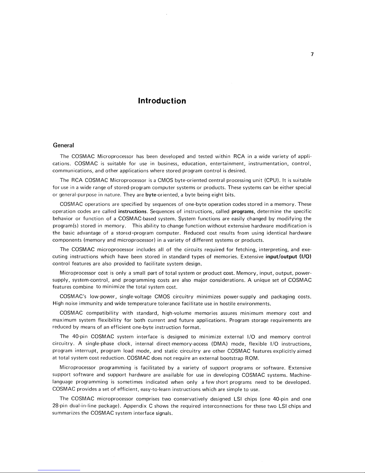
Fig. 1
illustrates a typical
can
be
performed
a)
control
b)
transfer
c)
movement
d)
interpretation
of
input/output
of
Fig. 1 -
by
COSMAC
binary
of
data bytes between
or
Block
computer
include:
(I/O)
data between
modification
RAMIROM
65536
BYTES
MAX.
diagram
system
devices,
I/O
and
different
of
bytes stored in
MWRITE
of
typical
incorporating
memory
memory
CPU
STATE
MAC
TIMING
COS
computer
the
COSMAC
(M),
locations,
memory.
N
(41
CODE
(21
(21
DMA/INT.
(31
FLAGS
(41
DATABUS(BI
system using
I/O
CONTROL
CKTS
the
microprocessor.
____
jr
______
TIMING
DEPENDING
SYSTEM
92C5-
COSMAC
J
B MSC.
1/0
DEVICES
26554
microprocessor.
ON
Operations
that
Page 10
COSMAC Microprocessor
_____________________________
_
9
For example, COSMAC can control
store
them
in
predetermined
using
the
stored
System
numbers
input
devices may include switches,
and
modems, analog-to-digital converters,
lights,
CRT
/lED/liquid-crystal
Memory can comprise
(Read-Only Memory)
(Random-Access Memory)
changes.
storage
eight-bit
RAM
capacity
Bytes are
data
is
also required
is
determined
transferred
bus.
Fifteen COSMAC I/O
depending
instruction.
of
the
code, an I/O
permits
the
or
modes.
Four
that a byte
binary
are active. Use
A program
response.
termined
rupt,
rupt
Two
These
be immediately
on
required I/O sophistication. A
It
can be used
data
bus,
or,
status
simple, inexpensive
meaning
of
I/O flag
the
inputs
transfer
input
lines if desired.
of
the
interrupt
The
interrupt
sequence
of
COSMAC resumes
line by resetting its
additional I/O lines are provided
lines are called direct-memory-access (DMA) lines. Activating
stored
DMA-out line causes a
built-in
sets this
to
number
the
memory
pointer
next
higher
of
consecutive
pointer
to
an initial
any
is
used
is
between ·1/0 devices,
control
to
alternatively,
code,
or
control
word
on
are provided. I/O devices can activate these
is
required,
flag inputs
line can be activated
causes COSMAC
operations
execution
interrupt-enable
in a
byte
register
memory
memory
bytes
the
entry
of
binary-coded decimal numbers
memory
transfer
locations. COSMAC can
the
results
to
an
paper-tape/card
photodetectors,
devices, digital-to-analog converters, modems, printers,
combination
for
permanent
of
RAM
storage
of
required for general-purpose
for
temporary
by
the
specific application
storage
memory,
signal lines are provided. Systems can use
four-bit N code
specify an I/O device
to
specify
an I/O
the
They
of
data
that
can be
must
control
a small
bus facilitates systems incroporating a large
an
error
tested
be
coordinated
to
designed
of
to
the
interrupted
to
whether
code.
number
condition
by COSMAC instructions
at
any
suspend its
respond
flip-flop (I E).
for
special
types
memory
to
location
be immediately
is
used
to
indicate
without
transferred
the
location. Each DMA
location.
to
and
Repeated
from
memory
activation
independent
from
then
output
perform
display
specified
or
printing device.
readers, magnetic-tape/disc devices, relays,
and
other
computers.
and
ROM
up
to a maximum
programs, tables,
computer
of
variable
of
and
systems which require
data.
the
system.
COSMAC by means
and
The
Output
other
type
of a common,
some
is
generated by
the
be involved in an I/O-memory
an I/O
Use
of
with
time
to
program. COSMAC
affecting
byte
of
the N code
I/O devices
has
occurred,
programs
by I/O circuits
current
the
interrupt
of
byte
transfer
the
from
memory
memory
byte
location
transfer
of
a DMA line can cause
of
concurrent
represents
or
inputs
that
data,
to
directly
modes. Use
at
any
etc.
These flags can also be used
to
determine
test
them.
to
obtain
program sequence
condtion.
can
be made
between
the
DMA-in line causes an
COSMAC program being
to
the
requesting
for
the
automatically
program
an
input
keyboard
arithmetic
operations
devices may include
and
other
computers.
of
types
of
memory
65,536
of
bytes. ROM
fixed
data.
frequent
and
program
required
bidirectional
or
all
of
these signals
COSMAC
byte
input/output
transfer
by means
an I/O device selection
specify an I/O device
of
the N code
number
time
to
whether
an
immediate
and
After servicing
to
memory
to
specify
of
I/O devices
signal COSMAC
or
not
COSMAC
execute
a prede-
the
ignore
the
and
I/O devices.
input
byte
executed.
output
circuits. A
DMA cycles.
increments
the
The
the
transfer
program
pointer
execution.
RAM
they
interinter-
of
and
as
to
The
any
I/O device circuits can cause
program
immediate
program. Use
four
indicates
two-bit
A
signals
must
sample a flag line
COSMAC response regardless
of
DMA provides
COSMAC
permit
whether
state
synchronization
COSMAC
data
to
determine
the
quickest
code
and
is
responding
transfer
of
two
of
I/O circuits
to a DMA
by
activating a flag line,
when
it
becomes
the
program
response
timing
currently
with
lines are provided
with
internal COSMAC
request,
active. Activating
in
progress, suspending
least
disturbance
for
responding
the
interrupt
of
use
operating
to
line,
or
a DMA line. A
the
interrupt
line causes an
operation
the
program.
by
I/O device circuits. These
cycles.
The
an
interrupt
request,
of
that
state
code
executing
Page 11
10
__________________________________
an
input/output
signal a new processor
set
and
reset
Bytes are
lines
to
control
the
data
is
generated
level
instruction,
I/O
controller
transmitted
memory
bus
and a memory
which
or
state
code,
flip-flops.
to
and
read/write
write pulse
is
used by
none
to
from
the
of
thp.se. The
latch
memory
cycles. During a
is
system
timing
memory
by
generated
to
gate
signals are used
address bits,
means
of
memory
by
COSMAC
the
memory
the
write
output
to
take
common
cycle,
at
the
byte
by
the
memory
memory
the
appropriate
data
from
data
bus. COSMAC provides
byte
to
be
time. A memory
onto
the
common
User Manual
and
I/O systems
the
bus,
written
data
appears
bus.
for
and
the
to
to
two
on
read
COSMAC provides eight
form
of
two
successive 8-bit bytes. The more significant (high-order) address
address lines first, followed by
required
4096-byte
from
timing
eight
for
input
operation
step.
mode
COSMAC
results in a
sixteen general-purpose 16-bit
binary
decimal digits (0,1,2, ... E,F)
Appendix
0011.
order
individual 16-bit
16-bit A register.
lines
the
incremented
register
N,
left half
can be
hex digit in N are
to
select a
memory
the
high-order address
pulses
address lines. An internal COSMAC register holds
the
remainder
Three
additional
determines
with
The
load signal line holds
is
discussed
strobes
of
operating
system
in
would
the
the
Architecture
Fig. 2 illustrates
number
code.
A.
Using hex
R (3).0 refers
(more significant)
Three
4-bit
for
memory
8-bit
data
to
be used as a
The
notation
or
P, respectively. Fig. 3 illustrates
of
Fig. 3 illustrates
written
This expression indicated
the
of
Hexadecimal (hex)
notation,
to
registers labeled N, P,
scratch
The
read/write
bus
for
or
decremented
R(X), R(N),
as
to
be placed
memory
unique
lines
memory
require a 12-bit address. This 12-bit address
byte
the
required high-order bits
memory
complete
speed.
circuits if desired. A single clear
section
and
internal
system
R (3) refers
the
low-order (less significant) eight bits
byte
of
pad registers.
two
A-register
operations.
subsequent
counter.
or
the
that
address
the
less significant (low-order) address
byte
with
the
cycle. No
the
on
external
the
COSMAC microprocessor
The
external clock may be
COSMAC microprocessor in
Memory
Notation
structure
advantages. The COSMAC
scratchpad
notation
and
their
binary equivalents
to
the
16-bit
R(3).
and
The
bytes
Either
transfer
by 1 and
R(P)
initial
into
returned
is
used
the
contents
the
low-order 8 bits
the
8-bit
lines. These eight lines
location
8 bits
and
of
the
registers. Each
will be used here
X hold 4-bit binary
16
are sequentially placed
to
to
transfer
D register. The designated
depends
from
the
low-order address
into
an address latch (register)
the
eight
latch circuits are required
input
Control
COSMAC microprocessor. This simple,
scratch
bits
of
the
refer
of
R(N)_O
Interface.
architecture
scratchpad
(0000,0001,0010,
pad register
contained
the
D register.
to
to a scratchpad
of
various registers (hex
in
two
A-register
the
selected
a scratch pad register
-7
D
contained
supply
byte.
on
the
size
low-order address bits
system
stopped
to
The
and
initializes internal COSMAC
the
program load
is
based on a register array
register, R,
refer
to
designated
or
byte
of
codes
(hex digits)
a selected
on
the
bytes
16-bit
scratch
register selected
notation).
in
the
scratch
scratch
16-bit
memory
byte
The
number
of
the
memory.
is
obtained
byte.
One
when
for
the
low -order address
interface. A single-phase
started
to
is
4-bit
binary
...
,1110,1111)
or
selected by
R (3). R (3).1 refers
scratch
pad can be
eight
external
(A.O/ A.1) can also be gated
val
ue in
the
pad register
byte,
designated by
The
pad register designated
pad register
addresses in
appears
by
of
synchronize
mode.
designated by a
codes.
that
A register can also be
to
by
operation
on
of
high-order bits
For
combining
the
two
they
appear
on
the
address lines
circuitry
The
unique
architecture
The
are listed in
the
are used
copied
memory
permit a scratch
the
4-bit
N,
is
left
the
the
eight
example,
4 bits
COSMAC
on
the
byte.
clock
COSMAC
in
one
use
of
this
comprising
4-bit
16
hexa-
binary
code
to
the
high-
to
select
into
the
address
to
pad
code
in
X,
to
D.
The
performed
by
the
unchanged.
a
Page 12
COSMAC Microprocessor
_____________________________
11
MEMORY
ADDRESS
(4)
R SELECT
'"":&-.....,,"""~:-i
R(9).1
R(9).0
R(
AU
R(A).O
R(E).I
R(F).I
(8)
SCRATCH
-REG
(8)
I STE
R
PAD
RS
I/O
COMMAND
8
-BIT
92CM-26420
BUS
BI-DIRECTIONAL
DATA
BUS
(8)
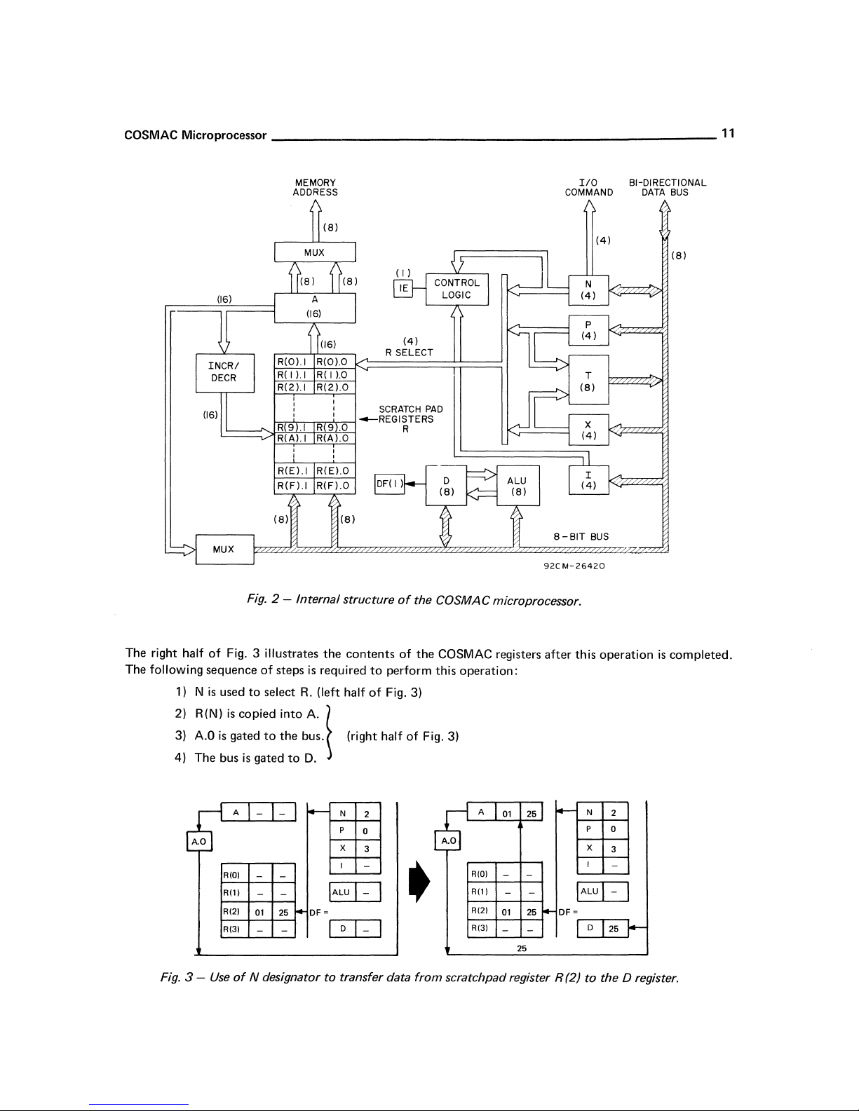
Fig. 2 - Internal structure
The right half
of
Fig. 3 illustrates
The following sequence
1) N is
2) R(N)
3)
4) The bus
Fig. 3 -
A.O
used
to
is
copied into A. \
is
gated
is
A
~
RIOI
Rill
RI2J
R(3)
Use
of
N designator
of
select
to
gated
- -
- -
- -
01
-
steps
the
to
~
25
-
the
is
required
R.
(left half
bus.
D.
-
DF=
to
contents
to
of
(right half
N
2
p
0
X
3
I
-
IALU
I-
I
D
I-
I
I
transfer data
of
the COSMAC microprocessor.
of
the
COSMAC registers
perform this
operation:
Fig. 3)
of
Fig. 3)
A
01
A.O
RIO)
- -
R(ll
- -
R(2)
•
from
scratchpad register R (2) to the D register.
R(31
01
- -
25
25
25
after
f---
I--
DF=
this
operation
N
p
X
I
IALU I-
D
25
is
completed.
2
0
3
-
I
I-
Page 13
12
__________________________________________________
__
User Manual
for
the
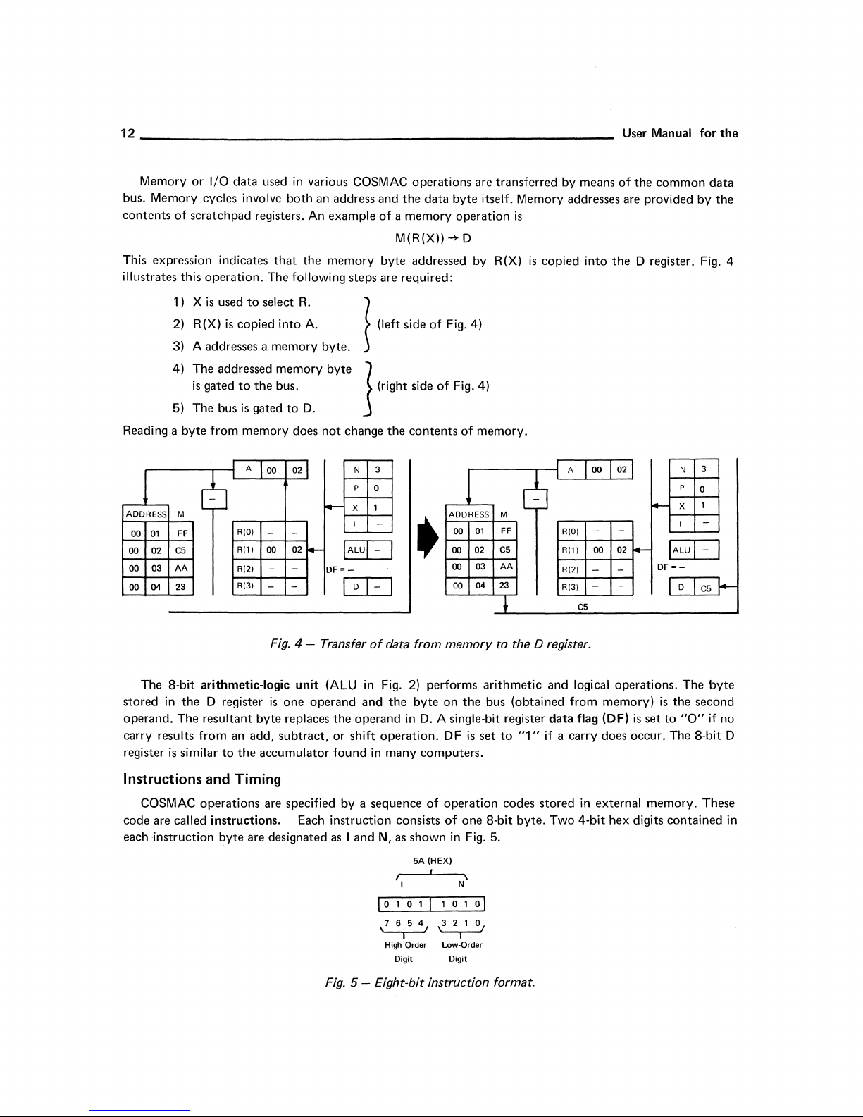
Memory or I/O data used
bus. Memory cycles involve
contents
This expression indicates
illustrates this operation. The following steps are required:
Reading a byte from memory does
ADDRESS M
00
00
00
00
of
scratchpad registers. An example
1)
X
is
used
to
2)
R(X)
is
copied into A.
3)
A addresses a memory byte.
4)
The addressed memory
is
gated
to
5)
The bus
is
A
6
01
02
03
04
FF
C5
AA
23
R(O)
R(l)
R(2)
R(3)
that
select
the
gated
00 02
-
00
-
-
in
various COSMAC operations are transferred by means
both
bus.
to
-
-
02
-
the
R.
D.
~
an address and
memory byte addressed by R(X)
byte
not
change
N
p
x 1
l-
I
IALUI-
DF=-
D
I
the
data
of
a memory operation
M(R(X))
~
(I.ft
,;d.
of
J I,;.h.
3
0
the
,;d.
of
contents
-
I
I-
I
of
the
common
byte itself. Memory addresses are provided
is
-+
D
is
F;
F;
•.
41
•.
41
of
memory.
copied into
the
D register. Fig. 4
by
data
the
Fig. 4 - Transfer
The 8-bit arithmetic-logic
stored
in
the
D register
operand. The
carry
results from an add, subtract, or shift operation. DF
register
Instructions and
COSMAC operations are specified by a sequence
code are
each instruction byte are designated
resultant byte replaces
is
similar
to
the
Timing
called instructions. Each instruction consists
unit
(ALU
is
one operand and
accumulator
Fig. 5 -
of
in
Fig. 2) performs arithmetic and logical operations. The
the
operand
found
in
as
I and N, as shown
10
,7654,
Eight-bit
data
from
memory
the
byte on
in
many computers.
5A
I \
I N
1 0 1 I 1 0 1 0 I
I
High Order Low-Order
Digit Digit
the
D.
A single-bit register
is
of
operation codes stored
of
one 8-bit byte. Two 4-bit hex digits contained in
in
Fig. 5.
(HEX)
~
----.-
instruction format.
to
the D register.
bus (obtained from memory)
data
set
to
flag (DF)
"1"
if a carry does occur. The 8-bit D
in
is
external memory. These
set
byte
is
the
second
to
"0"
if no
Page 14
COSMAC Microprocessor
The
execution
propriate instruction
values in I and N specify
struction
Fig. 3,
memory bytes representing instructions.
registers can be used as a program
which scratch pad register
instruction fetch cycle are
R (1) as
placed
then
next machine cycle will perform
cycle,
Alternately repeating instruction fetch
are stored
type.
or
acts as a special code, as described
Instructions
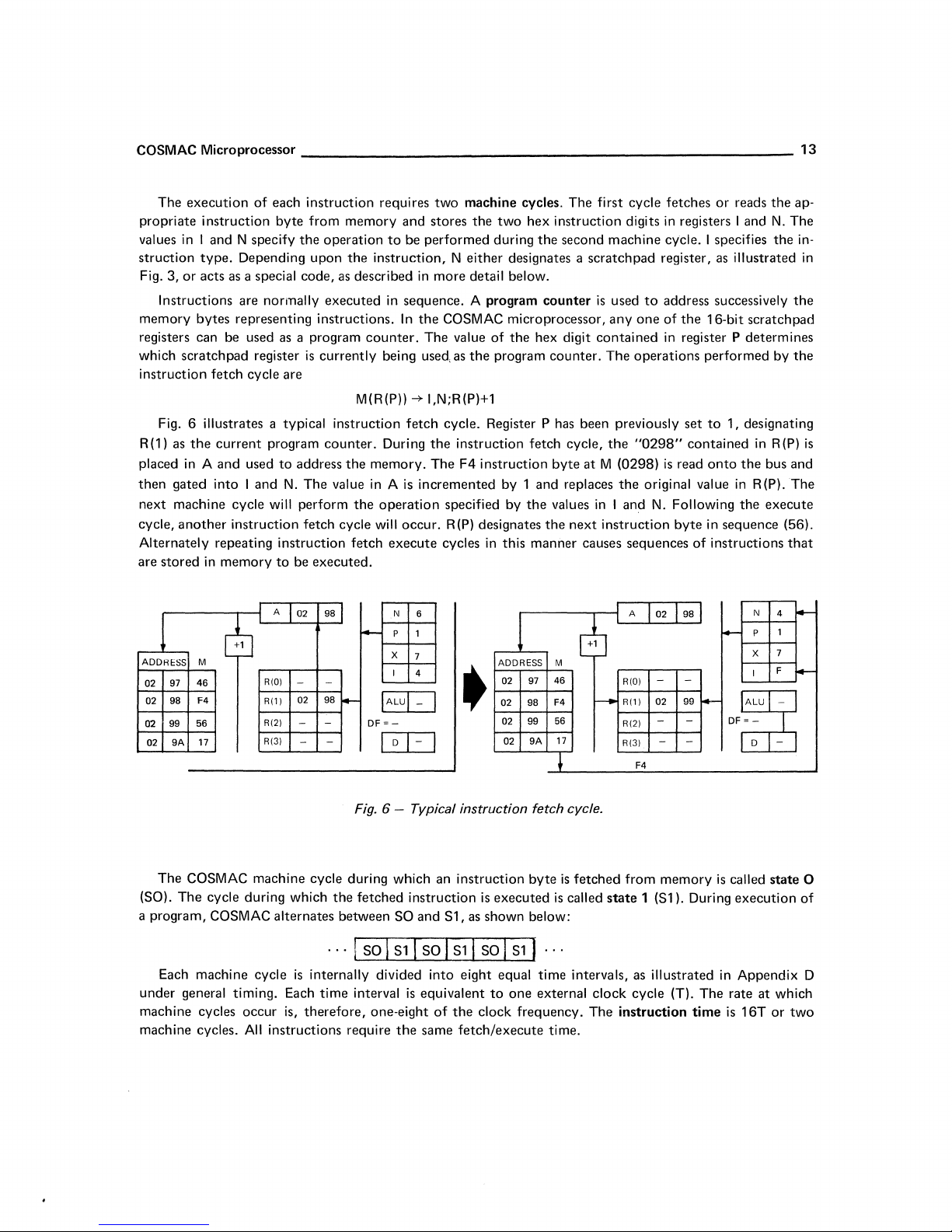
Fig. 6 illustrates a typical instruction
the
in
A and used
gated into I and
another
in
of
Depending upon
are normally executed
current
instruction fetch cycle will occur.
memory
_____________________________
each instruction requires
byte
from memory and stores
the
operation
the
instruction, N
counter.
is
currently being used, as
M{R{P))
program
to
counter.
to
address
N.
The value in A
be executed.
the
memory. The F4 instruction
the
operation
two
machine cycles. The first cycle fetches
the
two
hex instruction digits
to
be performed during
either
designates a scratch pad register, as illustrated
in
more detail below.
in
sequence. A program
In
the
COSMAC microprocessor,
The value
-+ I,N;R{P)+l
fetch
cycle. Register P has been previously
During
the
is
incremented by 1 and replaces
execute
cycles
of
the
the
program
instruction fetch cycle,
specified by
R{P)
designates
the
in
this manner causes sequences
in
registers I and
the
second machine cycle. I specifies
counter
hex digit
counter.
the
byte
values
next
is
used
anyone
contained
The
the
at
M (0298)
the
in
I and
instruction
to
address successively
of
the
in
register P determines
operations performed by
set
"0298"
contained
is
read
original value
N.
Following
byte
of
13
or
reads
the
ap-
N.
The
the
in-
in
the
16-bit scratchpad
the
to
1, designating
in
R (P)
is
onto
the
bus and
in
R{P).
The
the
execute
in sequence (56).
instructions
that
A
02
98
cfu
ADDRESS
02
02
02
02
(SO).
a program, COSMAC alternates between SO and S1,
M
46
97
F4
98
99
56
17
9A
The COSMAC machine cycle during which an instruction
The
cycle during which
R(O)
R(l)
R(2)
R(3)
- -
02 98
-
-
-
-
-
the
...
Each machine cycle
under
general timing. Each
machine
machine cycles.
cycles occur is,
All
is
internally divided into eight equal time intervals, as illustrated
time
therefore,
instructions require
N
6
P 1
-
X
7
I
4
IALul-
DF=-
I
Fig. 6 - Typical instruction fetch cycle.
fetched instruction
I SO I
interval
one-eight
D I-
S1
I SO I
is
equivalent
the
I
•
I
Sl
of
the
same
fetch/execute
as
I SO I
A
02
ADDRESS
02 97
02
98
02
99
9A
02
byte
is
executed
shown below:
S1
I
to
one
clock frequency. The instruction
M
46
F4
56
17
~
is
fetched
is
called
...
external
time.
cb
R(O)
R(l)
r--
R(2)
R(3)
from
state
clock
-
02
-
- -
F4
memory
1 (S1). During execution
cycle (T). The rate
98
I
I-
-
99
-
- DF
is
in
time
N
4
p
1
--
7
X
F
I
~
=-
D -
~
called
state
0
of
Appendix D
at
which
is
16T
or
two
Page 15

14
Page 16
Instruction
Repertoire
15
Each COSMAC instruction
during
the
execute
are divided
Register
internal COSMAC registers.
Memory Reference - Two instructions are provided
ALU
operations.
I/O
eight instructions
Branching -
Control - Six control instructions facilitate program
operations.
Each instruction
provided using a symbolic
shown
It should be
illegal codes and should
into
Operations - This group includes six instructions used
Operations
Byte Transfer - Eight instructions are provided
in
this section for most instructions. A
cycle
six general classes:
- This
to
transfer
Fourteen
is
designated
noted
that
is
fetched during SO
S1
are
determined
group
contains
data
from
different
any unused machine codes, such as
not
conditional and unconditional branch instruction are provided.
by
its two-digit hex
notation.
be
used by users.
by
the
fifteen instructions
memory
A two- or three-letter abbreviated
to
summary
They
Register Operations
11
N INCREMENT
When 1=1,
FFFF+1=0000.
the
scratch pad register specified by
and
executed
two
hex digits
to
load
to
I/O control circuits.
interrupt,
code
and by a name. A description
of
the
are reserved for
R(N)+1
the
hex digit
during S1. The
contained
or
store a
for
load
memory
operand
instruction repertoire
"CN"
"31
future
in N is
to
count
memory
performing
from
name
",
"72",
use by RCA.
incremented
operations
in I and
and
selection,
is
N.
to
move
byte.
arithmetic
I/O
control
or
of
also given. Examples are
is
given
"01
",
etc.,
performed
These
operations
data
and logical
circuits,
branch
the
operation
in
Appendix
are considered
INC
by
1.
between
and
Note
and
link
is
A.
that
A
02
+1
03
RIOI
Rill
01
RI21
- -
RI31
02
Fig.
FF
I--
7A
32
FF
7 - Example
f4-
DF
IALU
~-
I
N
p
X
I
I-
D
I
3
0
2
1
I
AB
I
of
instruction
+f
•
r-
TN
A
02 FF
03
7A
01
32
-
-
03
00
l-
RIOI
Rill
RI21
R(31
-INCREMENT.
l-
DF
N
p
x 2
I
IALU
~-
D
I
I-
I
3
0
1
AB
I
I
Page 17
16
User Manual
for
the
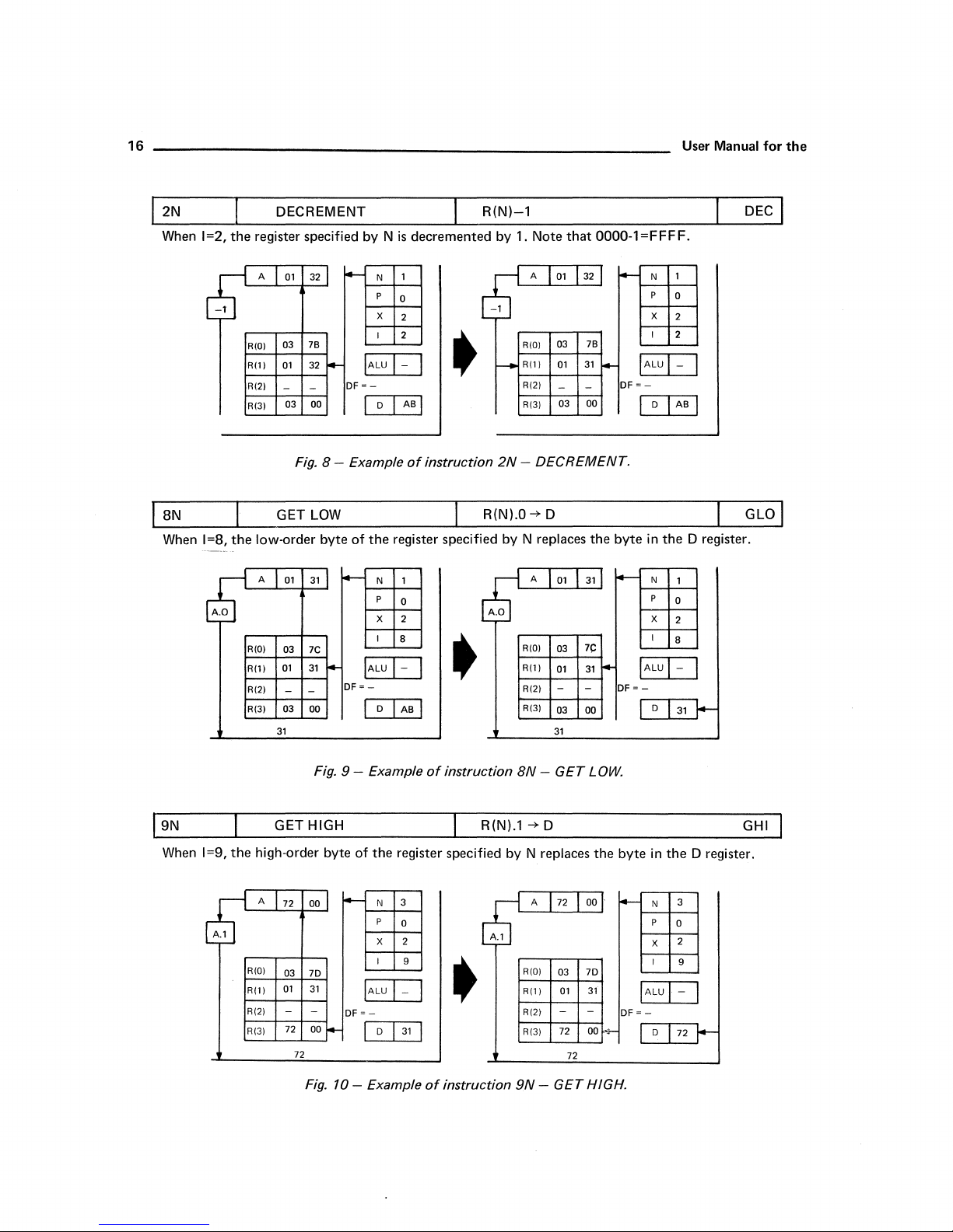
2N DECREMENT
When
1=2,
the
register specified by N
A
01
32
~
-T
03 7B
RWI
01
32
- -
03
Fig.
01
03
01
- -
03 00
00
LOW
31
7C
31
4-
DF
8 - Example
byte
of
-
..
DF=
8N
When
1=8,
A.O
Rill
RI21
RI31
GET
the
low-order
A
RIOI
Rill
RI21
RI31
31 31
R(N)-l
is
decremented by 1. Note
1
N
p
0
X
2
2 I
IALU
I-
=-
I
the
IALU
-
I
I
D
I AB I
of
instruction
register specified by N replaces
N 1
p
0
X
2
I
B
I-
I
D
I AB I
-1
-
•
2N
R(N).O-+ D
•
that
0000-1=FFFF.
A
01
32
7B
03
RWI
01
Rill
RI21
RI31
- DECREMENT.
{ A
RWI
Rill
RI21
RI31
31
- -
03 00
01
7(:
03
01
31
-
-
03 00
~
the
31
f4-
-
DF
byte
-
DF=-
IALul
=-
I
IALU
N
P
X
I
D
in
N
P
X
I
D
1
0
2
2
-
I AB I
the
D register.
1
0
2
8
I-
31
DEC
I
I
Fig. 9 - Example
GET HIGH
When
1=9,
the
high-order byte of
A
72
00
A.l
RIOI
03 7D
01
- -
72
72
31
00
Fig.
Rill
RI21
RI31
~
DF
=-
f4-
10
- Example
of
instruction
R(N).l
the
register specified by N replaces
N 3
p
X 2
I 9
IALU
D
I
I-
I
0
I
31
I
•
of
instruction
~
9N -GET
8N -GET
-+
D
72
A
RIOI
03 7D
01
Rill
-
RI21
72 00
RI31
72
LOW.
the
00 .
31
-
.;-
HIGH.
byte
-
DF=
in
N
p
IALU
-
X
I
D
the
D register.
3
0
2
9
I-
72
GHI
I
Page 18
COSMAC Microprocessor
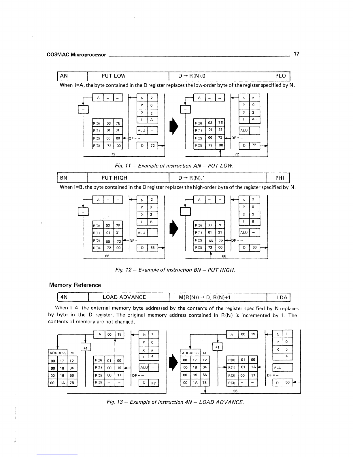
PUT LOW
When I=A,
the
byte
_____________________________
D--*
contained
in
the
D register replaces
the
R(N).O PLO
low-order
byte
of
the
register specified
by
_
17
N.
When I=B,
~
the
-1
A
RIOI
R(1)
RI21
RI31
PUT HIGH
byte
contained
A
03
RIOI
Rill
RI21
00
R131·
66
-
03 7E
01
31
00
00 I-DF
72
72
Fig.
- -
01
31
72
-
7F
00
00
72
I+-
N
t--
p
X
I
IALU
~-
D
11
- Example
in
the
D register replaces
N
l-
p
X
I
IALU
DF~
D 66
2
0
2
A
I-
I
72
•
of
instruction
D--*
the
2 A
0
2
B
I-
I
•
A
-
03 7E
RIOI
Rill
00
RI21
RI31
AN -PUT
R(N).l
high-order
- -
03
RIOI
01
Rill
RI21
R(31
-
l-
31
01
72
72
00
1
LOW.
byte
IALU
DF
~-
I-
72
of
the
l-
7F
31
66 72
72 00 D
t
66
I+-
DF
IALU
~-
N
2
p
0
2
X
A
I
I-
I
D
72J--
PHI
register specified by
2
N
p
0
2
X
I
B
I-
I
66 r-
N.
Memory
When
by
byte
contents
ADDKIoSS M
17 12
00
18
00
19 56
00
lA
00
Reference
1=4,
the
in
the
D register.
of
memory
~
34
78
LOAD
external
memory
are
not
A
00
R(oI
01
Rill
00
00
RI21
RI31
- -
Fig. 13 - Example
Fig. 12 - Example
ADVANCE
byte
addressed
The
original
memory
changed.
N
p
X
I
IALul-
~-
D I F7 I
I
1
0
2
4
of
00
19
-
19
-
17
DF
of
instruction
M(R(N))
by
the
address
I
•
instruction
BN -PUT
--*
contents
contained
ADDRESS M
17
18
1A
12
34
56
78
00
00
00 19
00
t
4N -LOAD
HIGH.
D;
R(N)+1
of
the
in
R(N)
dJ
r-
ADVANCE.
register specified by N replaces
is
A
RIOI
RI11
RI21
R(31
56
incremented
19
00
01 00
lA
01
17
00
-
-
I--
-
DF
by 1.
N
p
X
I
IALU
~-
D
The
1
0
2
4
I -I
56..1-
Page 19
________________________________________________________________
18
User Manual
for
the
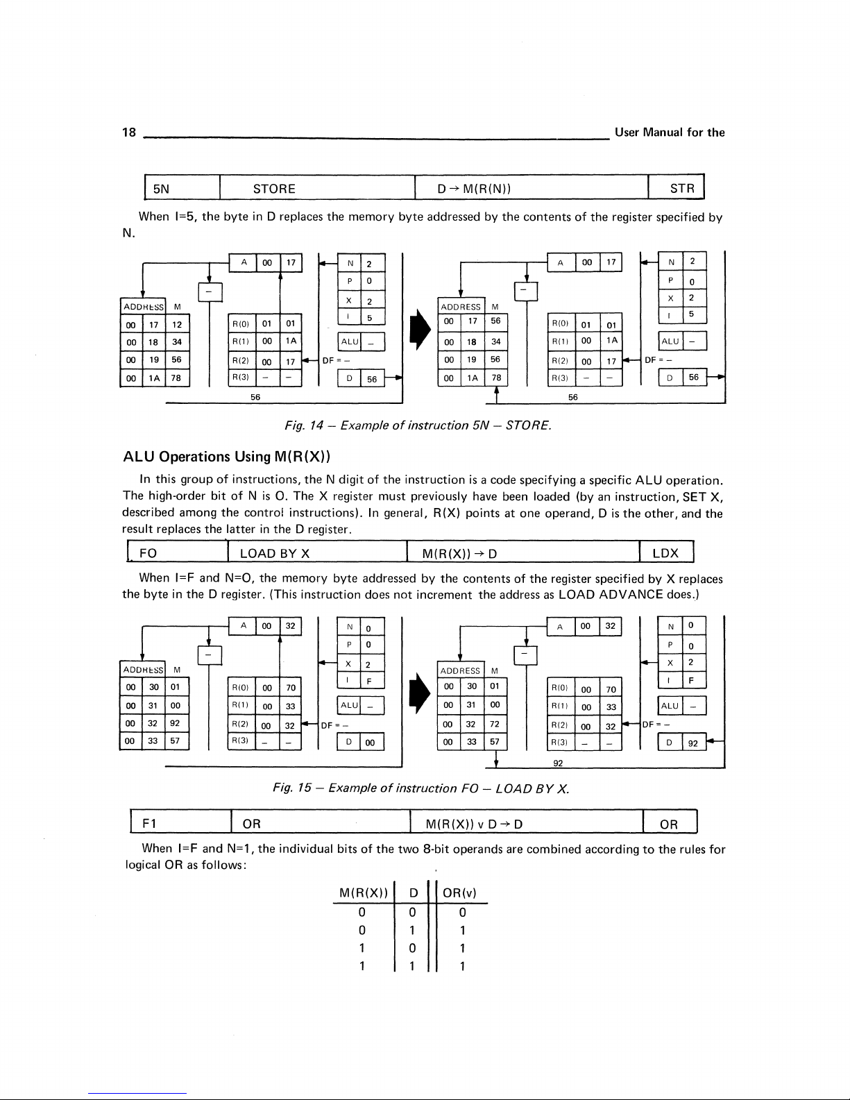
5N
When 1=5,
N.
ADDHt:SS M
17
00
00 18
00
00
ALU
The
described
result
the
12
34
56
19
78
1A
Operations Using
In
this
group
high-order bit
among
replaces
FO
When
I=F
byte
in
the
STORE
the
byte
in
A
00
cb
01 01
RIOI
00
Rill
RI21
00
RI31
-
56
of
instructions,
of N is
the
control
the
latter
in
I LOAD
and
N=O,
the
D register. (This
D replaces
171
lA
17
I-
-
f-
the
DF
X
IALUI-
=-
Fig. 14 - Example
M(R(X))
the N digit
O.
The
X register
instructions).
the
D register.
BY
X
memory
byte
instruction does
memory
N
2
p
0
2
I
5
D
56
of
must
In
addressed
byte
I
of
instruction
the
instruction
previously
general,
not
increment
D -i> M(R(N))
addressed
ADDRESS M
17
00
18
00
19
00
1A
00
is a code
R(X)
points
M(R(X))
by
the
contents
STR
by
the
contents
6
56
34
56
78
f
5N
- STORE.
specifying. a
have
been
at
one
-i> D I LDX ]
of
the
the
address
of
A 00
RIOI
01
00
Rill
RI21
00
RI31
-
56
loaded
(by an
operand, D is
register
as LOAD
the
register specified
17
l-
01
1A
DF
17
r-
-
specific
ALU
instruction,
the
other,
specified
by
ADVANCE
N
p
X
I
IALul
=-
D
operation.
and
X replaces
does.)
2
0
2
5
-
56]-
SET
by
I
X,
the
ADDHcSS
30
00
31
00
32 92
00
00 33
F1
When I=F
logical
M
01
00
57
OR
cb
and
as
follows:
A
RIOI
Rill
RI21
RI31
OR
N=1,
32
00
l-
70
00
33
00
32
00
-
-
Fig. 15 - Example
the
individual
-
IALUI
DF
=-
I
bits
M(R(X))
N
p
x
I
D 1
0
0
2
F
-
00
of
a
a
I
•
I
of
instruction
the
two
D
a
a
ADDRESS M
00 30
31
00
32
00
00
33
FO -
M(R(X)) v D
8-bit
operands
OR(v)
a
01
00
72
57
LOAD
-i>
are
BY
D
combined
A
RIOI
Rill
RI21
RI31
92
X.
32
00
70
00
33
00
I-
32
00
-
-
according
l-
DF=
to
N
x
I
IALU
D
OR
the
P
0
0
2
F
I-
92
rules
I
for
Page 20
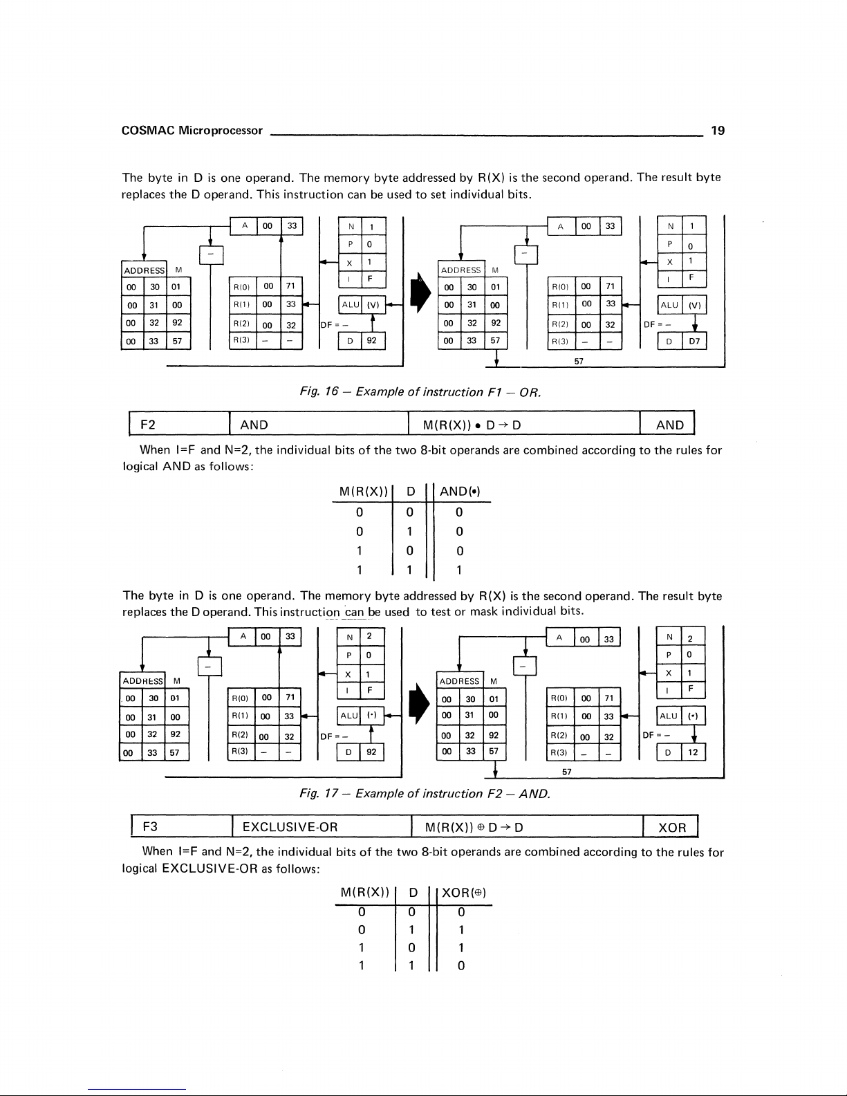
COSMAC Microprocessor
The
byte
in D
is
one operand. The
replaces the D operand. This
memory
instruction
can
byte
be
addressed
used
to
by
R(X)
is
the second operand. The result
set individual bits.
19
byte
A
00
6
30
31
32 92
33
F2
When
byte
30
31
32
33
M
01
00
57
I=F
and N=2, the individual bits
AND
as
follows:
in D
is
one operand. The
cb
M
01
00
92
57
RiOl
Rill
RI21
RI31
AND
A
RIO)
Rill
R(2)
R(3)
00
00
00 32
-
00
00
00
00
-
ADDRESS
00
00
oo
00
logical
The
replaces the D operand. This
ADDH~SS
00
00
00
00
33
71
33
-
-
Fig. 16 - Example
f-
OF
=-
N
1
p
0
1
X
F
I
ALU
(V)
t
92
D
of
the
M(R(X))
r-
o 0 o
o 0
memory
instructi~n
33
f-
71
33
I-
OF=-
32
-
Fig.
17
byte
_~a~be
N
P 0
used
2
x 1
I F
I·)
ALU
f
92
D
- Example
•
of
instruction
M(R(X)).
two
8-bit
D
o 0
addressed
to
test
•
of
instruction
ADDRESS M
00
01
30
00
31
00
00
00
AND(·)
ADDRESS M
00
00
00
00
00
92
32
57
33
F1
- OR.
D
-?-
operands are combined according
by
R(X)
or
mask
individual
01
30
00
31
92
32
57
33
+
F2 -AND.
RIOI
Rll)
R(2)
R(3)
D
is
the
second operand. The result
bits.
A
cb
RIOI
Rll)
R(2)
R13)
57
71
33
00
32
00
57
33
00
71
00
00
33
32
00
-
-
N
AND
to
the
rules
N
p
X
~
I
I-
OF
=-
D 12
~
0
for
byte
2
0
1
F
F3
When
I=F
logical
EXCLUSIVE-OR
EXCLUSIVE-OR
and N=2,
the
individual bits
as
follows:
of
the
M(R(X))
o 0
o 1
two
I
M(R(X))
8-bit
D
o
Ell
D
operands are
XOR(Ell)
o
o
-?-
D
combined
according
to
XOR
the
rules
for
Page 21
20
_______________________________
User Manual for
the
The 0 byte.and M(R(X)) are
be used
ADDRESS
00
00
00
00
30
31
32
33
to
compare
M
01
00
92
57
two
A
cb
R(O)
Rill
R(2)
R(31
the
two
bytes for equality since identical values will result in
33
00
-
00
71
33
00
-
00
32
-
-
'"
Fig.
18 - Example
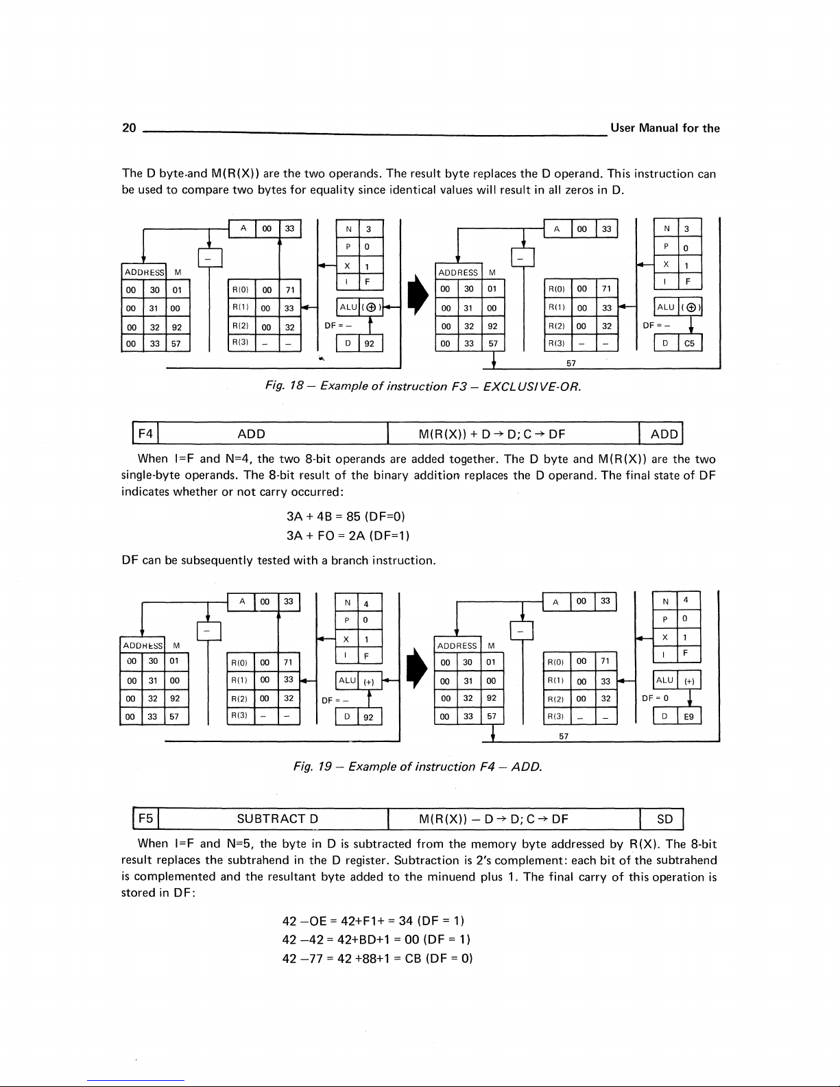
ADD
When I=F
single-byte operands. The 8-bit result
indicates
OF can be
and
whether
N=4, the
or
two
not
carry occurred:
8-bit operands are added together. The 0
3A + 4B =
3A+
FO = 2A (OF=1)
subsequently tested with a branch instruction.
operands. The result byte replaces
N 3
p
0
X
DF
1
I
F
ALU
(@)/--
=-
t
•
92
of
instruction
binary addition replaces
(OF=O)
of
D
the
85
ADDRESS
00
00
00
00
M(R(X))+O~O;C~OF
M
30
01
31
00
32
92
33 57
F3
- EXCLUSIVE-OR.
the
0 operand. This instruction can
all
zeros
in
O.
R(O)
00
71
R(lI
R(21
R(3)
57
00
00
33
32
I Aool
byte
and
M(R(X)) are
the
0 operand. The final state of OF
N
the
3
0
two
cb
ADDHI:SS
00
00
00
00
result replaces
is
stored
M
01
30
31
00
32
92
33
57
When I=F
and
the
complemented and
in
OF:
A
RIOI
Rill
R(21
R(3)
33
00
71
00
33
00
32
00
-
-
Fig. 19 - Example
SUBTRACT 0
N=5,
the
byte
subtrahend
the
in
resultant byte added
42
42
42
-
ALU
-
DF
=-
in 0 is
the
0 register.
-OE
= 42+F1+ =
-42
= 42+BO+1 =
-77 = 42
N
4
p
0
X
1
I
F
(+1
/--
t
D
92
subtracted
+88+1 =
ADDRESS M
01
30
00
31
00
00
•
00
of
instruction F4 -
M(R(X))-O~O;C~OF
from
Subtraction
to
the
minuend plus 1.
34
(OF = 1)
00
(OF = 1)
CB
(OF = 0)
00
92
32
57
33
the
memory byte addressed by R(X). The 8-bit
is
2's complement: each
ADD.
The
00
RIOI
R(lI
00
00
RI21
RI31
-
57
final carry
71
33
32
bit
of
the
of
this operation
4
N
0
P
SO
subtrahend
is
Page 22

COSMAC Microprocessor
21
A final value
in D
is
ADDAcSS
00
30
31
00
00 32
00
33
When I=F and N=7,
byte replaces the minuend in D. This operation
ADDHcSS
30
00
31
00
00
32
33
00
exactly
M
01
00
92
57
M
01
00
92
57
of
"0"
in DF indicates
100
(hexadecimal) greater than the
A
00
33 N
6
6
RIO)
00
RI1
)
00 33
R(2)
00 32
R(3)
- -
Fig.
SUBTRACT
the
A
00
RIO)
00
R(1)
00
00
R(2)
R(3)
-
-
71
I-
OF
20
- Example
M
memory
33 N 7
-
71
~
33
32
-
that
the subtrahend
5
p
0
X
1
I F
ALU
1-)
=-
t
0
92
of
byte addressed
p
a
x
1
I
F
ALU
OF
HI-
=-
t
0
92
was
larger than the minuend.
true
(negative) difference.
ADDRESS M
00
30
00
31
00
•
instruction
D·M(R(X)) ~ D; C ~ DF
by
is
identical
•
32 92
00
33
F5 -SUBTRACT
R(X)
is
to
F5
ADDRESS M
30
00
31
00
00
32
00
33
A
c6
01
00
57
1
subtracted
with
01
00
92
57
RIO)
R(1
)
R(2)
R(3)
D.
from
the operands reversed.
R(O)
R(1
R(2)
R(3)
)
57
57
00
00
00
00
-
the
00
00
00
In
this
case
33
l-
71
33
I-
OF
32
-
byte
in D. The result
71
33
32
ALU
= a
SM
the
N
p
x
I
0
N
p a
value
5
a
1
F
1-)
~
C5
Fig. 21 - Example
SHIFT
When I=F and N=6, the 8 bits in D are shifted right one
D
bit
is
placed in DF. The final value
instructions in this group,
operand or
to
divide
by
M(R(X))
2.
RIGHT
of
is
not
1
RIO)
-
-
R(1)
-
-
R(2)
R(3)
-
-
Fig.
DF~
-
-
22
- Example
Cirili
the
high·order D
used. This
6
P a
x 1
I F
of
instruction F7 -
ISHI
of
instruction
SUBTRACT
FT D RIGHT 1 BIT;
bit
position. The original value
bit
is
always
instruction
•
can
R(O)
- -
R(1)
- -
R(2)
- -
R(3)
- -
F6 -SHIFT
LSB
"0".
be
~
In
this
used
to
RIGHT.
M.
DF;
0
~
MSB I SHR
of
the
instruction,
test successive bits
P a
6
x 1
I F
m
LU-
OF
= 1
~
o
79
low·order
unlike
other
of
the
Page 23

22
ALU
Operations Using M(R(P))
In
this
group
of
ALU
bits
of N are a code
In
general,
immediate
The
use
pointers
to
byte.
of
them.
specifying
R (P)
points
The
D register supplies
immediate
instructions,
the
same
to
one
of
data
is
a useful
the
N digit has a 1
ALU
the
operands,
the
second
way
operation
the
operand,
to
avoid
in
the
as
instructions
byte
in
memory
and
setting
high-order
using
after
then
receives
up
special
bit
position.
M(
the
the
constant
User Manual
The
R (X) l.
except
instruction
result.
areas
remaining
when
N=6.
byte,
called
in
memory
for
three
the
the
and
When I=F
byte
in
execution
next.
This
and
R(N)
ADDK~SS
27
03
03 28
03 29
2A
03
and
N=8,
D.
Because
ofthis
instruction
the
instruction,
is
LDX uses R(X).
6
M
F8
92
F9
57
RIO)
R(1)
R(2)
R(3)
OR
LOAD IMMEDIATE
the
one
A
memory
current
of
three
LDI
03 28
the
byte
program
instruction
which
and
LDA
i+-
03
28
I-
71
00
33
00
-
-
Fig.
23
- Example
IMMEDIATE
OF
IALUI-
=-
I
immediately
counter
byte
load D
each
increment
8
N
p
0
X
2
I
F
I
o
121
1
of
instruction
M(R(P)) -+
following
represented
following
from
memory.
the
ADDRESS M
03
03
03
•
03
F8 -LOAD
M(R(P)) v D -+
D;
R(P)+1
the
current
by
R(P)
is
incremented
the
immediate
byte
It uses R(P) as a
pointer
after
use,
cb
27 F8
28 92
29 F9 R(2)
2A
57
+
IMMEDIA
D;
--
R(P)+1
instruction
again
placed in D will be
pointer,
but
LDX
does
A
03 28
RIO)
R(1)
R(3)
92
03
00
00
-
TE.
29
I-
71
33
-
I
LDI
byte
replaces
by 1 during
while
LDA
not.
N
p
-
X
I
IALUI,-
OF
=-
0
ORI
I
the
the
fetched
uses
8
0
2
F
1
92 I--
When I=F
the
memory
ADDKbS
03
27
03 28
03 29
03
2A
M
F8
92
F9
57
and
N=9, a logical
byte
immediately
6
A
RIO)
Rill
R(2)
R(3)
03
03
00
00 33
- -
Fig.
OR
following
2A
i+-
2A
-
71
24
- Example
operation
the
N
p
X
I
ALU
OF
=-
0
is
F9
instruction
9
0
2
F
(V)
t
92
of
instruction
performed
ADDRESS M
03
03
03 29
•
03
is
F9
similar
the
second
27 F8
28
92
F9
2A
57
~
- OR
to
F1.
The D byte
operand.
cb
RIO)
--
R(1)
R(2)
R(3)
IMMEDIA
A
57
TE.
The
03
03
00
00
-
is
one
operand,
result goes
2A
I-
28
I--
71
OF
33
-
X
ALU
=-
0
to
N
p
I
D.
9
0
2
F
(V)
+
07
and
Page 24

COSMAC Microprocessor
AND
IMMEDIATE
I M(R(P)) . D -+
D;
R(P)+l
23
ANI
When I=F and
the
memory
ADDRESS M
2B
2C
20
2E
When
FA
OF
FB
Fa
I=F
03
03
03
03
operand, and
instruction
ADDRESS M
2B
20
2E
2C
FA
OF
FB
Fa
03
03
03
03
N=A,
byte
immediately
dJ
and N=B,
the
can
be
used
dJ
Fig.
a logical
AND
following
03
03 2C
00
00
-
Fig.
2C
t-
71
33
-
25
- Example
A
R(QI
R(ll
R(21
R(31
EXCLUSIVE-OR
an
EXCLUSIVE-OR
memory
A
R(OI
Rill
R(21
R(31
26
byte
to
complement
2E
03
'
2E
03
f-
71
00
33 DF
00
-
-
- Example
operation
the
FA
N
A
p
=-
X
I
ALU
0
0
2
F
('1
r
07
I+-
OF
of
IMMEDIATE
immediately
the
D register when
N
B
p
I-
of
0
X
2
I
F
«!)
ALU
=-
t
0 07
instruction
is
performed similar
instruction
ADDRESS M
03 2B
03
03
•
03 2E
instruction
FA -
I M(R(P))
operation similar
following
I
FB -
the FB
the
ADDRESS M
03
03
03
•
03
EXCLUSIVE-OR
to
F2. The D
is
the second operand.
cb
FA
r---
2C
OF
FB
20
Fa
~
AND
IMMEDIA
EB
D -+ D;
immediate
R(P)+l
to
F3
is
instruction
byte
performed. The D
c6
FA
2B
2C
20
2E
t-
OF
FB
Fa
l
IMMEDIA
R(OI
R(ll
R(21
R(31
A
R(OI
R(ll
R(21
R(31
byte
is
one operand, and
A
03
2C
20
03
-
71
00
33
00
-
-
OF
TE.
is
the
second operand. This
is
"F
F".
2E
03
2F
03
~
71
00
33
00
-
-
FO
TE.
N
A
p
~
OF
0
X 2
I F
=-
o 07
~
XRI
byte
is
one
N
B
p
ALU
=-
0
X
I F
«!)
0
2
F7
)
+
I-
OF
ADD
IMMEDIATE
When I=F and N=C,
byte
immediately
dJ
2F
30 80
FD
31
92
32
M
FC
ADDReSS
03
03
03
03
the
following
A
03
RIOI
03
Rill
RI21
R(31
two
the
00
00
-
Fig. 27 - Example
operands
FC
30
f-
30
71
33
-
are
instruction
C
N
p
X
I
ALU
=-
D
of
0
2
F
(+)
F7
instruction
r-
DF
added
is
t
I
M(R(P))+D
as
the
other
•
-+
in F4. The D
operand.
ADDRESS M
FC
2F
03
30 80
03
31
03
03 32
FD
92
~
FC -
ADD
D;
C -+
DF;
byte
is
c6
r---
IMMEDIA
R(P)+l
one operand, and
80
00
00
03
03
-
30
71
33
-
31
-
A
R(OI
R(ll
R(21
R(31
TE.
the
~
OF
ADI
N
p
X
I
ALU
=-
0
memory
C
0
2
F
(+)]
1
77
Page 25

________________________________________________________________
24
User Manual
for
the
When I=F
memory
ADDH~SS
03
2F
03
30
03
31
32
03
When I=F
the
memory
equivalent
ADDRESS
33
03
34
03
35
03
36
33
and
byte
immediately
c6
M
FC
80
FD
92
and
byte
to
FD
cb
M
FF
lA
62
6A
SUBTRACT
N=D,
the
following
A
03
RIOI
03
Rll)
00
R(2)
00
R(3)
- - D 77
Fig.
28
- Example
SUBTRACT
N=F,
the
immediately
with
the
operands
03 34
A
RIO)
03
R(l)
00
R(2)
00
R(3)
-
Fig.
29
- Example
D IMMEDIATE I M(R(P))-D
two
32
71
33
32
l-
operands
f--
the
FD
N D
p
X
I
ALU
~-
DF
of
instruction
are
subtracted
instruction
0
2
F
HI-
f
•
M IMMEDIATE I D-M(R(P))
two
operands
following
are
the
subtracted
FF
instruction
reversed.)
F
N
p
0
X 2
I F
ALU
H
~-
f
lB
D
of
instruction
•
34
71
33
-
4-
OF
-
-+
D; C
-+
DF;
R(P)+1
as
in
F5.
is
the
minuend.
ADDRESS M
03
2F
03
30
03
31
03
32
FD
- SUBTRACT D
as
in
F7.
represents
ADDRESS
03
33
34
03
35
03
03
36
The D byte
c6
FC
80
FD·
92
+
-+
D; C
-+
The D byte
the
cb
M
FF
lA
62
6A
t
f--
f--
is
A
03
RIOI
03
RllI
00
R(2)
00
R(3) -
92
IMMEDIA
DF;
R(P)+1
represents
subtrahend.
A
03
RIO)
03
R(l)
00
00
R(2)
-
R(3)
lA
the
TE.
FF -SUBTRACT M IMMEDIATE.
I SDI I
subtrahend,
32
1
I-
33
-
71
DF
33
-
I SMI I
the
minuend,
(This
instruction
34
I-
35
-
71
DF ~ 1
33
-
ALU
~
ALU
1
D
D
and
N 0
p 0
X
I
N
p
X
I
2
F
H
+
lB
F
0
2
F
H
1
01
the
and
is
Input/Output
Byte Transfer
N=O-7
When 1
four
ADDRESS M
00
00
00
00
bits
31
32 34
33
34
=6
of N are
cb
12
56
78
and
N=O,1
simultaneously
A
RIO)
Rll)
R(2)
R(3)
,2,3,4,5,6,
00
33
03
36
71
00
33
00
- -
Fig.
30
OUTPUT
or
7,
sent
from
N 7
p
x
f--
I 6
IALul-
DF~-
I-
D I -
I
- Example
the
memory
COSMAC
r+
0
2
of
I
I
M(R(X))
byte
to
7
•
instruction
-+
BUS; R(X)+1
addressed
the
ADDRESS M
00
31
00
32 34
00
33
00
34 78
I/O
by
system,
c6
12
56-
+
6N
(N=0-7J - OUTPUT.
R (X)
is
placed
and a specific
A
RIO)
Rll)
R(2)
-
R(3)
56
00
03
00
00
10UTI
on
the
data
bus.
The
code
is
provided
-
OF
N
p
X
I
!ALU
~-
I D
33
36
71
34
~
-
-
I-
I-
7
0
2
6
r+
on
7
I
I
56
Page 26

COSMAC Microprocessor
the
COSMAC
PUT". The I/O system recognizes these
significant bits
so
that
If X is
as immediate
When
1=6
not
modified. The
state
code
should gate an
specify which
ADDREoSS
31
00
32
00
33
00
34 78
00
state
of
successively
set
to
the
data.
and
N=8,9,A,B,C,D,E,
(1=6)
is
input
of
the
cb
M
12
34
56
______
N=8-F
_____________________________
code
lines
to
indicate I/O (1=6).
N specify which
executed
same value
four
bits
provided.
byte
8 possible
A
00
of
the 8 output
output
of
onto
34
instructions can
as
P,
then
INPUT
or
F, an
N are simultaneously
The
most
the
data
input
instructions
I
l-
36
03
RIOI
Rill
RI21
RI31
~2~7
71
00
34
00
I-
-
-
_____________
Fig.
31 - Example
DF
IALul-
=-
I
Branching
The
current
over immediate
condition
When a
low-order
the
byte
with
the
(or back
usefulness.
30
When
"30"
replaces R
-
ADDRESS M
01
21
01
22
01
23 82
01
24
program
data
is
tested.
branch
byte
of
following
instruction following
to
the
beginning
1=3
and
(P)
counter,
bytes. When 1=3, a
If
the
test
condition
R(P). The
the
branch instruction.
of
UNCONDITIONAL BRANCH
N=O,
an unconditional branch
.0.
01
A
cb
F6
30
2A
RIO)
Rill
RI21
RI31
Fig.
-
01
00
- -
32
- Example
R(P), normally steps sequentially
is
satisfied, a
is
satisfied,
next
instruction
the
immediate byte. This ability
the
same sequence
23
-
-
23
37
-
DF
IALul-
=-
I
of
conditions,
thf!
byte
input
significant
bus during
A
r-
N
A
p
0
x
2
I 6
I
D
I-
I
~~27
of
instruction
branch
branch
the
byte
byte
If
the
to
operation
N
0
1
P
2 X
I
3
I
D
I-
I
instruction
The
most significant bit
and reads
instructions
transfer
immediately following
BUS
byte
replaces
sent
bit
of N is
the
is
being
executed.
ADDRESS M
00
00
00
•
00
the
output
is
being
bytes from successive
-+
M(R(X))
the
memory
from COSMAC
'"
",
execute
31
32
33 56
34
cycle.-
R(X)
12
34
27
f
6N
(N=8-FJ
through
instruction
is
effected
immediately following
will be fetched
test
condition
form
a loop)
M(R(P))
ADDRESS M
•
30 -UNCONDITIONAL
is
executed.
by changing R(P).
from
is
not
to
branch
is
fundamental
-+
R(P).O
is
performed.
21
30
22
23 82
24
F6
2A
01
01
01
01
~
of N is
byte
executed.
the
byte
to
indicating
The
is
not
A
cb
RIOI
Rill
RI21
RI31
-INPUT.
a list
the
branch
the
memory
satisfied,
to
The
byte
A
c6
RIOI
Rill
R(21
RI31
BRANCH.
"0",
indicating
from
the
bus.
The
R (X)
is
incremented by ,
memory
output
addressed by R(X). R(X)
the
I/O system, and
"INPUT".
3 least significant bits
modified.
00
03
00
00
-
27
of
The N code
instruction replaces
then
a new instruction
to
stored-program
immediately following
-01
-
01
00
- -
82
locations.
instruction
34J
36
71
34
I-
-
instructions, skipping
location specified
execution
23
-
82
I-
37
is
IINP
The
I/O circuits
N
p
x
l-
I
IALU
DF
=-
I D
specifies
continues
computer
N
p
I-
X
I
IALU
DF
=-
read
the
I-
I-
sequence
I D
f
"OUT-
3 less
I
of
A
0
2
6
which
0
1
2
3
I-
I-
25
out
is
I/O
N
A
I
I
27
the
by
the
I
I
Page 27

26
---------------------------------------------------
User Manual
for
the
BRANCH
When
1=3
and N=2, a conditional branch operation dependent on the value
in D
is
examined and
R
(P)
is
incremented
be
skipped
so
that
This instruction can
if
it
by
1.
the next instruction in sequence
be
EXCLUSIVE-OR operation (F3
constant. A zero
branch
> the
next
ADDRESS
01
21
22
01
23
01
24
01
ADD
RESS
21
01
22
01
23
01
24
01
to
a location in the program
instruction in sequence
M
F6
32
97
2C
M
F6
32
97
2C
result byte in D
A
01
~
R(O)
- -
R(I)
01
R(2)
00 37
R(3)
-
A
01
cfu
R(O)
-
R(I)
01
R(2)
00
R(3)
-
IF
D=OO I M(R(P)) -+ R(P).O
is
equal
to
zero a branch operation
This increment
used
following
or
if
D;O!OO,
23
I+-
23
I-
-
23
I-
-
23
I-
37
-
causes
the branch
one
of
FB) might
would
for
X 2
ALU
DF=-
1
IALul-
DF=
-
1
be
used
represent equality. The
handling this value
possibly
N
p
I
o 1
N
p
X
I 3
2
1
3
-
00
2
1
2
to
I-
1
CONDITION
I
o
112
1
is
fetched and executed.
the
ALU
to
compare
of
look
for
ADDRESS
01
02
03
•
04
TRUE
ADD
RESS
01
•
01
01
01
IF
D=OO, OR R(P)+11 BZ I
of D is
performed. The
is
performed.
address
byte
If
the value
following
the
operations described earlier.
an
input
byte
with
a byte representing a
"32"
instruction could then
the
input
equality
M
21
F6
22
32
23
97
24
2C
~
M
F6
21
22
32
97 R(2)
23
2C
24
byte when
with
other constants.
dJ
c6
f----
A
R(O)
R(I)
R(2)
R(3)
97
A
R(O)
R(l)
R(3) -
D=OO,
01
- -
01
00
-
01
-
01
00
23
97
37
-
1
23
-
24
37
-
of D is
"32"
For
or
I-
I-
not
instruction
example,
be
used
to
proceed
N
p
I-
X
I
IALul
DF=
-
1 0
1 00 1
N
p
I-
X
I
IALU
I-
DF=-
112
I 0
2
1
2
3
-
2
1
2
3
byte
zero,
to
an
to
to
I
I
1
Fig.
33
- Example
of
instruction
BRANCH IF DF M(R(P)) -+ R(P).O
When
1=3
and N=3, branching occurs
Examples
condition
34
35
36
37
When
3,
or
processor
4)
are
tested.
1=3
is
to
not
shown
BRANCH
BRANCH
BRANCH
BRANCH
and N=4,5,6,
held in its
test the flags
for
IF
EF1
IF
EF2 M(R(P)) -+ R(P).O
IF
EF3
IF
EF4
or
"true"
as
required.
CONDITION FALSE
32 -BRANCH
if
DF=1. Otherwise, the
the remainder
of
M(R(P)) -+ R(P).O
M(R(P))
M(R(P))
7, branching occurs
state
by
external circuits. These
IF
D=OO
for
both
false
IF
DF=1, OR R(P)+1
next
instruction in sequence
the branching instructions
IF
EF1=1,
IF
EF2=1, OR R(P)+1
-+ R(P).O
-+ R(P).O
only
when the corresponding external flag
IF
EF3=1, OR R(P)+1
IF
EF4 =1,
four
because
OR
OR
branch instructions
and true conditions.
I BDF I
is
performed.
they
differ
only
R(P)+1
R(P)+1
B1
B2
B3
B4
mput
permit
in the
(EF1 ,2,
the micro-
Page 28

COSMAC Microprocessor
_____________________________
27
SKIP
When
1=3
and N=8, the
BRANCH I F
When
1=3
and
N=A,
instruction in sequence
A
ADDRESS M
21
01
22
01
01
23
24
01
When
and executed.
3C
~
F6
3A
97
2C
1=3
R(O)
R(1)
R(2)
R(3)
BRANCH
and N=B, a branch occurs
BRANCH
byte
D~OO
a branch
is
executed.
23
01
- -
01
23
00 37
- -
Fig.
34
IF
NO DF
IF
NO
following
is
performed
N
P
-
X
I
IALul-
-
OF
=-
o
I
- Example
only
EF1
R(P)+1
the
"38"
instruction
M(R(P)) -+ R(P).O
only
if
the byte in D does
A
1
2
3
I
112
•
I
of
instruction
M(R(P))
if
M(R(P))
-+ R(P).O
DF=O. Otherwise, the
-+
R(P).O
is
skipped.
IF
D100, OR R(P)+1
ADDRESS M
01
21
F6
01
22
3A
01
23
97
24
01
2C
~
3A -BRANCH
IF
DF =
IF
EF1=0, OR R(P)+1
not
equal zero;
01
A
23
cb
R(O)
- -
R(I)
R(2)
R(3)
97
IF
DIDO.
0,
OR R(P)+l BNF
next
instruction in sequence
01
00
- -
97
37
,
If
-
it
I-
SKP
BNZ
does, the
N
p
X 2
I
IALU
I-
DF=-
I 0
lId
is
fetched
BN1
next
A
1
3
I
3D
3E
3F
When
or
4)
is
in its
Because
locations
limited
location in memory
The special
treated
branch does
struction on the last
other words, the address
as
BRANCH
BRANCH
BRANCH
1=3
and N=C,D,E,
"0"
only
that
can
to
28 or
case
follows:
not
state.
the low-order byte
be
branched
256
bytes. Each 256-byte memory segment
are
of
If
a branch takes place, R(P).1
take place, execution continues at the first (Oth) byte
byte
IF
NO EF2
IF
NO EF2
IF
NO EF4
or
F, a branc occurs
of
to
is
described in the section on Machine Code Programming.
a branch instruction and its immediate
of a page
of
the immediate
always leads
M(R(P))
M(R(P))
M(R(P))
R(P). can
limited. Since
byte
-+
R(P).O
-+ R(P).O
-+
R(P).O
only
when the corresponding external flag
be
modified
only
the low-order 8 bits can
is
is
not
changed --the branch stays on the
into
the
next
determines the
Control
WAIT
FOR
I
to
IDLE
put
out
the
two
time
timing
the
IDLE
pulses
instruction
for
I/O
100
When 1=0 and N=O, the microprocessor repeats execute (S1) cycles
out
is
activated, at which
continues
INTERRUPT/DMA-IN/DMA-.oUT
is
terminated. During
synchronization.
IF
EF2=0, OR R(P)+1
IF
EF3 = 0, OR R(P)+1
IF
EF4 = 0, OR R(P)+1 BN4
by
a branch instruction, the
be
modified, branching
called a
byte
page
page.
Methods
occupying the last
of
the next
page,
either
by
branch
to
which a branch takes place.
until
an
interrupt,
IDLE,
for
two
page.
or
DMA-in,
the microprocessor
BN2
BN3
input
(EF1 ,2,3,
range
of
branching
bytes in a
same
page.
A branch in-
by
increment. In
IDL
memory
to
any
page
If
or
DMA-
is
is
a
Page 29

_______________________________________________________________
28
User Manual
for
the
DN
When I=D,
pad register
beginning
any
location
EN
When I=E,
I/O
byte
transfer
SET
P
the
digit
contained
is
to
be used as
at
M(R(N)). It facilitates
in
memory_ (These
-
RIO)
R(l)
R(2)
R(3) -
SET
X
the
N digit replaces
operations.
the
A
-
-
01
00
in N replaces
program
topics
-
-
23
37
-
Fig.
35
N-+P
counter.
"branch
OF=
and
are discussed in
N
8
p
1
X
2
I
0
IALU I -
-
0
I-
I
- Example
N-+X
the
digit
in
the
f-
8
I
I
X.
digit in
This
link"
of
P.
instruction
functions,
the
section
•
instruction
This
instruction
This
operation
causes a
on
R(O)
R(l)
R(2)
R(3)
DN -SET
jump
subroutine
Machine
-
-
01
23
00 37
-
-
is
used
SEP
is
used
to
to
the
nesting,
Code
Programming.)
N 8
specify
which scratch-
instruction
and
long branches
8
x
o
OF
=-
D
1-
I
P.
SEX
to
designate R (X) for ALU
sequence
to
and
rl
-
R(O)
R(l)
R(2)
R(3)
Interrupt Handling
The
special
an
interrupt.
storing
interrupt
"1"
into P and
flip-flop (IE)
interrupt
interrupt
When an
the
values
of X and
forces X
servicing are discussed
to
and P to
"2"
"0".
A
I-
-
01
00'
I-
I
-
23
37
- -
Fig.
servicing
interrupt
into
Also, a specific
occurs,
P,
and
be
automatically
X.
In
addition,
in
N 3
p
1
X
2
I
E
IALU
I-
OF=-
0
I-
I
36
- Example
instructions
it
is
to
set X and P to
further
code
the
section
r-
3
I
•
I
of
instruction
can
best
necessary
transferred
interrupts
is
provided
on
I/O
Interface.
R(O)
-
-
R(l)
01
23
R(2)
00
37
R(3)
EN -SET
be
understood
to
save
the
new
values
into a temporary
are disabled by resetting
on
the
-
-
by
examining
current
for
the
COSMAC
N 3
X 3
OF
=-
I 0
X.
COSMAC's response
configuration
interrupt
register (T),
state
code
E
1-
I
to
of
the
machine
service program. The
and
forces a value
the
interrupt
lines. Details
by
of
enable
of
the
Page 30

COSMAC
Microprocessor
29
78
When
register
at
instruction
70
When
memory
is
set.
ADDRESS
01
21
00
01
22 00
01
23
01
24 00
1=7
the
can
1=7
byte
M
43
INTERRUPT
- -
RIOI
Rill
00
RI21
01
RI31
02
IE = 1
Fig.
SAVE
and
N=8, a
memory
then
replace
RETURN
and
N=O, a
addressed
A
Gb
RIOI
Rill
RI21
RI31
ACTION
56
DF
24
3C
37
- Example
SAVE
location
the
original X
RETURN
by
R(X),
01
23 N
-
-
56
00
01
23
I-
02
3C
. .
Fig.
38
X,P -+
T;
1 -+
P;
2 -+ X; 0
N N
P 3
X 4
RIOI
Rill
=-
D
1-
of
operation
addressed
operation
and
P
x
l+-
I 7
IALUI-
OF
=-
D I-
I
1
instruction ---
T -+
M(R(X))
is
performer'.
by
R(X).
and
P values
M(R(X))
is
R(X)
is
incremented
0
1
2
I
I
RI21
RI31
INTERRUPT
This
Subsequent
to
resume
-+ X,
P;
performed.
ADDRESS M
01
01
01
•
01
IE = 0
operation
R(X)+1;
by
21
22
23
24
- -
00
01
02 3C
(or
return
The
1.
00
00
43
00
56
execution
-+
IE
24
ACTION.
stores
to)
1 -+ IE
digits in X
The
c6
I----
+
- Example
of
instruction
70
- RETURN.
t----+----i
X 2
DF=
-
I D
1-
the
of a RETURN
normal
and
1-bit
Interrupt
01
A
RIOI
- -
Rill
00 56
01
RI21
RI31
02
43
I
byte
contained
program
P are
23
24
t-
3C
or
execution.
I
replaced
Enable
OF
SAV
in
the
DISABLE
RET
I
by
(IE)
N
0
P 3
4
x
7
I
IALU
I -
=-
I 0
I-
T
the
latch
l-
I-
I
I
71
When
While I E=O,
Either
in
the
section
Instruction
The
following
inputs
two
the
process.
DISABLE
1=7
and
the
the
R ETU
on
Utilization
bytes
N=1, an
interrupt
RN
Machine
table
shows
from
different
instruction
line
or
DISAB LE
Code
the
similar
is
ignored
by
instruction
Programming.
use
of
some
sources,
compares
M(R(X))
to
RETURN
the
processor.
of
the
-+ X, P;
can
be used
preceding
them,
and
is
outputs
R(X)+1;
° -+ IE
executed,
to
set
or
instructions
the
except
reset I E,
that
respectively, as
to
form a program.
larger. It
in
then
this
case
This
continues
DIS
IE
is
explained
program
to
repeat
reset.
Page 31

30
The
first
four
I/O
and
for
doing
specific numbers,
instructions
arithmetic.
noting
(at locations
The reader
the successive contents
0001,3,4,
unfamiliar
of
and 5) set
with
computers should trace
M(OOOO),
up
0,
and R(3).0.
R(2)
as a pointer
through
User Manual
to
address
the
program
for
0000
the
for
with
M ADDRESS M BYTE OPERATION
0000 00
0001
0002
0003 A2
0004
0005
0006 68 INPUT 0
0007
0008
0009
OOOA
OOOB
OOOC
DODD
OOOE
OOOF
0010
0011
Fig.
39
- Example
and
outputting
As
a more practical and complicated example,
multiplicand
The
byte
to
be
This program
the
multiplier
cand
right,
added
right
or
the
is
assumed
is
in
R(4).1, and the
multiplies
and the
multiplier
to
be
in
by
shifting
multiplicand
and the
product
F8
00
B2
E2
FO
69 INPUT 1
A3
F7
38 BNF
OF
83
52
60
30
01
of
program
memory
product
the
multiplier
left
both
"OO"~
~R(2).0
D~R(2).1
2~X
M(R(2))~D
~R(3).0
D-M~D;
R(3).~D
D~M(R(2))
OUTPUTO;
BR
the
larger.
as
addressed
will
(by
left.
COMMENTS
Data Storage.
D
C~DF
R(2)+1
for
the
be
and
adding
Execution starts at 0001.
1
Immediate
Sets
1
1
1
inputting
R(2) = 0000.
Prepare
Read
1st input data
Transfer it
Read
2nd input data to M(R(2)) = M (0000).
Save first data.
Subtract;set
Branch
ie.
if
2nd
1st
input, otherwise:
Retrieve first data.
Store
Output larger value; M( R (2)
Go
back
Immediate address byte.
two
following
by
register R(3). The
placed in R(4).1 and
product
it
to
itself),
data.
to
input.
to
M(R(2))
to
D.
DF
to
to
it
at M (0000).
next step.
OOOF
if
DF = 0,
input
greater
to
beginning: 0001.
bytes,
than
)~I/O.
compared
program segment
R(4).0 --two
right
eight times. Alternatives
or
the
multiplier
= M (0000).
them,
multiplies
multiplier
left
two
is
in R(5).0, the
bytes.
are
and the
multipli-
bytes,
to
shift
M ADDRESS M BYTE OPERATION COMMENTS
0100
0101 F8
0102
0103
0104
0105
0106 A5
0107 94
0108
0109
E3
80
A4
85
F6
3B
OD
~X
8~D
D~R(4).0
R(5).~D
D/~D
~R(5).0
R(4).1~D
BNF
1
1
J
Prepare
for
The
down,
Fetch multiplier,
shift
and
Fetch partial result.
If
location
instruction at
bit
in 80 (10000000)
using R (4).0
it,
put
it
back.
bit
shifted into DF
0100;
otherwise:
01
will
as
a counter.
is
0, branch
(cont'd on next
DA.
be
shifted
to
pa,ge)
Page 32

COSMAC
(cont'd)
Microprocessor
31
M ADDRESS M
010A
010B 33
010C 10
010D
010E 30
010F
0110 F6 D/2
0111
0112
0113
0114
0115
0116
0117 F6 D/2 Shift low byte I
0118 30
0119
011A
011B F9
011C
011D
011E
011F
0120
NOTE: The
essentially restore,
SHIFT
BYTE
F4
F6 D/2 Shift the result right I
13
F9
80
B4
84
33
lA
10
F6 D/2
80
A4
3B
04
RIGHT
instruction will
if
DF=l, a "1"
OPERATION COMMENTS
D+M(R(3))
BDF
BR
OR
immed
D
(data)
D~R(4).1
R(4).~D
BDF
BR
D
OR
immed
(data)
D~R(4).0
BNF
not
bit
into
shift the DF
the highest
bit
Add
in
If
carry
loc
J
J
J
}
}
]
]
of
0110;
and
go
of
result.
Shift
result
OR
in
from
instruction at
Store result
Fetch low byte
Delayed branch on shift in
010D
and branch
to
finish
Shift
low
and
OR
from
shift
Put
low
Branch back
80 hasn't shifted thru
Product
rest
of
bit
into
the highest
D after a SHI
multiplicand.
in
D
F,
branch
otherwise:
to
0113
to
shift the rest
right.
high
bit
for carry
010A
back.
of
result.
or
0110,
to
011A.
to
001 D
shift.
byte,
in high
bit
of
010D or 0110
byte
back.
("loop")
if
yet.
is
now ready. Continue to
program.
bit
of
RIGHT.
D.
FT
to
(NOTE).
(NOTE).
the original
These
operations
Fig.
40
- Example
result
of
program
to a third
byte.
for
multiplying
two
bytes
and
adding the
Page 33

32
Page 34

Memory and Control
Interface·
33
The reader will find
signal lines
except
that
Appendices
Memory Write (MWR) are made active by holding
be read, MREAD goes low (consistent with
Memory Interface
The use
the
T
A6780
of
attachment
RAM
ADDRESS
S-
DATA
IN
SITS
and
the
COSMAC
of
a static
chips. These
0-9
MEMORY
1024
SYTES
TA67S0
STATIC
RAM
CH IPS
Timing
memory
1024·byte
static
WE
I----<X'
CS
/4-------(X
interface lines
RAM. The 1024-byte read-write
single-power-supply chips are easy
B,
C,
and 0 are helpful while reading this section. Note
them
low, e.g., when
T2L
bus conventions).
is
best described by a specific example. Fig.
fi
MAO-I
MWR
to
memory
use.
COS
comprises eight
MAC
VCC
the
that
memory
41
shows
1024-bit
all
is
to
3-STATE
OUTPUTS
Fig. 41 -
Attachment
to
the COSMAC microprocessor.
DATA
BUS
of
a static 1024-bit Random-Access-Memory
92CS-26574
(RAM)
S SUS
PULL
UP
RESISTORS
122
K)
Page 35

34
_______________________________
User Manual
for
the
Ten memory address bits are required
byte
(A.1)
of
a 16-bit COSMAC memory address appears
two
least-significant bits are
strobed
timing.
MEMORY
ADDRESS
MEMORY
MWR
TIMING:
(MAO
TO
M
READ
(NOTE 2)
OUTPUT
MA
7)
2'ZW/ZI)
NOTES:
1. MINIMUM T DETERMINED
MEMORY WRITE PULSE WIDTH
2.
3.
MEMORY OUTPUT
"OFF"
4. SHADING INDICATES
VDD AND THE CLOCK SPEED.
to
select
lout
of
1024
memory
on
the
memory
into
the
2-bit address latch
~
I+-
T(NOTE
by
timing pulse A (TPA). Fig.
I)
V//https://manualmachine.com/I1~
I
'VALID
j
!.-ALLOWABLE
BY
INDICATES HIGH-IMPEDANCE CONDITION.
"DON'T
BYTE -""""""'NOTE 3
(ts=SETTLING
VDD--NO
(MWR);::::
CARE"
OR INTERNAL DELAYS DEPENDING
MEMORY
ACCESS
TIME)
MAXIMUM T
1.5
T
TIME
byte
location~high-order
addres~s
MAO-7 first. The
42
shows
k0?
~VALID
~
3.5T-ts
92CM-26472
BYTE
ON
the
Fig.
42
- Memory read/write timing.
The low-order
high-order bits have been
expansion
expansion. The MAO-7 lines may also require buffer circuits
to
byte
65,536
(A.O)
of
a 16-bit COSMAC
strobed
into
the
address latch. Latching
memory
bytes. Chip select decoding would have
address appears on
all
eight
to
be added
to
reduce
speed.
The
state
of
the
MWR
addressed
on
memory
the
data bus. It may be
A high MREAD
cuits can
data
byte
then
to
When a
sponding line
it
is
not
being driven.
Other
standard
and MREAD lines determine whether a
location. COSMAC controls
strobed
into an internal COSMAC register
line forces a high-impedance
place a byte
be written
data
bit
is
is
high. Eight bus pull-up resistors should be provided
RAM
into
true
to
be stored
the
addressed memory location.
("1
"),
the
corresponding bus line
types
are readily
the
destination
state
in
memory
accommodated
at
on
the
the
byte
is
of
the
memory
or
an external I/O register.
output
of
bus. A positive-going
is
low; when
to
place
by
the
COSMACinterface
must be consistent with clock frequency; e.g., a 2-MHz clock will require a
the
MAO-7 lines
A.1
bits would
to
the
latch
the
to
be read
load on
them
from
output
the
memory. COSMAC
MWR
data
is
false
the
bus
in a known
memory
with a
after
permit
output
for
to
achieve high
or
written
byte
when
it appears
or
pulse will cause
("0"),
the
state when
lines. Access
maximum
the
memory
memory
into
the
I/Ocir-
the
corre-
time
access
Page 36

COSMAC Microprocessor
time
of 1 microsecond.
sheets.
_____________________________
The
time
required
by
the
ALU
and
internal gating
is
specified
in
COSMAC
_
35
data
If a memory
separator
MREAD indicates a read cycle;
cycle
(see
For
various
fication
controls.
the
by
clock
does
not
have a 3-state high-impedance
gates,
otherwise
Appendix
memory
external
Dynamic RAM's can be used
may
be
stopped
it
is
used
the
0,
COSMAC Timing).
systems,
circuitry.
and
MREAD signal and
Segments
restarted
to
low MREAD line enables
control
of
ROM can be
with
appropriate
for
asynchronous
3-state
the
output,
outputs
MWR
attached
refresh circuits. Since COSMAC
memory
Control Interfaces: Starting, Stopping, and Loading
COSMAC requires an
A 2-MHz clock
125,000
During normal
places COSMAC
COSMAC
The
LOAD line permi1:s
supplied
can be
use
of
external
Fig.
43
system.
using a single
formed
gate
remains high. COSMAC design
switch
closures; a
frequency
instructions
operation,
in
LoAD"
from a keyboard,
ROM's
illustrates
All
logic consists
4007
from
short
per
an IDLE
input
or
one
chip
the
4007
first
external
would
second.
the
state
line
should
bytes
to
PROM's.
method
of
standard
provides a
gates
permits
clock
single-phase clock. Each
yield a 4-microsecond
COSMAC CLEAR line
by
forcing an IDLE
also be held high
be
sequentially
tape
reader, etc. This
of
using
the
~,
4000-series CMOS circuits. A free-running Pierce crystal oscillator
suitable
the
pulse will
gated clock. A high
oscillator
output
an
asynchronous
not
affect
machine
must
instruction
during
loaded
feature
CLOCK,
to
the
COSMAC
M READ
from
the
memory-output-bus
pulse
operation
machine
cycle
be held high. A
with
normal
into
memory
permits
CLEAR
COSMAC CPU. When
relationship
operation.
the
polarity
in
the
cycle
and
P=O, R
operation.
direct
and
LOAD lines
between
is
same
beginning
on
useful
for
driving
addressed
and
if
required.
consists
result in an
momentary
(0)=0000,
program loading
the
memory.
gates
width
manner,
of
Following
at M (0000).
to
control
CLEAR
the
free-running
eight
and
control
memory-bus
during
may
require
omitting
circuitry
clock
operating
low
on
I E=1.
CLEAR,
without
a COSMAC
lead
of
is
low, CLOCK
A low
the
the
is
pulses.
speed
this
Input
the
NAND
clock
on
read
modi-
write
static,
of
line
a low
bytes
the
and
The
two
toggle switches
Fig.
43,
the
CLEAR line
and
can also be used
If
the
LOAD switch
line will
iN,
The
line
it
be held low. COSMAC will remain
or
DMA-OUT line.
low
iJ)Aj)
Turning
in
off
high, and
an IDLE
state.
to
line causes COSMAC
the
LOAD switch
puts
the
control
is
held low
initialize
is
turned
Input
CLEAR
the
operation
and
I/O
circuits.
on,
the
circuits
(not
to
after a program
line
back
of
this
system.
the
CLOCK line
CLEAR line will go high,
in
an IDLE
shown)
return
to
can
to
the
has been loaded
a low
state.
is
held high. This CLEAR signal resets COSMAC
state
until a low occurs
then
activate DMA-IN
IDLE
state
This
sequence
When
both
the
clock
after
each
turns
off
resets COSMAC
switches are
will be
input
on
to
the
started,
the
load
byte
clock,
off,
as
shown
and
the
INTERRUPT,
bytes
into
memory.
is
loaded.
holds
the
once
again,
putting
in
LOAD
DMA-
LOAD
Page 37

_______________________________________________________________
36
NOTE:
FF
SET/RESET'
RUN
t
LOW
VCC
QI------'
User Manual
SCI
for
the
VCC
I
I
4007
X)-------,
r---------
I
I
I
I
VCC
I
I
1 1
1_
Fig.
43
- Two-switch COSMAC control.
Turning on the RUN switch starts the clock and puts a high
of
events
that
sequence
cau"ses a TPA
responds by performing a
state code
not
normally occur at this time) and
case,
the
high, the cycle immediately
signal
line (SCI) indicates
DMA
cycle does nothing more than take COSMAC
initiates program execution when the RUN switch
each
machine cycle. The
DMA
cycle (S2), which
that
COSMAC
causes
following
the
DMA
22M
20PF
-=
_____ ~ ________
low
on the
is
described in the section on
is
executing the
the
flip-flop
cycle
will
------1
COS
MAC
I
1
I
I
1
CLOCK
P
120
F
on
the
CLEAR
DMA-OUT
DMA
holding the
out
of
be
a normal instruction fetch operation (SO).
line
cycle (or
DMA-OUT
the
IDLE
1
---1
92CM-26473
line. Fig.
is
is
detected
I/O
interrupt
line
state. Since the
44
turned on. The clock
by
interface. A
cycle, which
low
to
be
COSMAC_
~In
shows the
low
on the
would
LOAD
line
It
this
is
OFF
RUN SWITCH
CLEAR
(LOWI
_____
CLOCK
TPA
DMA-OUT
w..
---'
I----IDLE
ON
L..J
I
,I
I
CYCLE
(SII----1.~I
Fig.
44
-
START
..
o__-
timing.
DMA-OUT
CYCLE
L
~
(S21--1
92CM-26471
Page 38

COSMAC Microprocessor
The
previous low
be
incremented
that
program
program
eliminated
tact
manual switches.
The
above
switches
execution
by
on
by 1.
The
execution
continues
example
having a
could
be used. Program
Other
represents
the
CLEAR
first
instruction
normally
until an IDLE
program
oscillators
line has
will,
begins
at
one
method
permanently
execution
could
be used
set
P=O
and
therefore,
M(0001)
instruction
of
initiating
stored
could
for
clock
R(O)=OOOO.
be
with
occurs
in
ROM.
also
generation.
fetched
R(O) as
or
the
system
Separate
be
initiated
The
DMA
from
M(0001)
the
program
RUN
switch
operation.
CLEAR
by
another
cycle
The
and
(S2)
and
counter.
is
turned
load
RUN
computer
caused
not
M(OOOO).
After
off.
operation
momentary
instead
37
R(O)
to
Note
initiation,
could
be
con-
of
by
Page 39

38
Page 40

I/O Interface
39
Programmed
The
following
under
program
Control
device
bus.
The
the
used
Interface.
or
to
gate
Data
output.
The
SCO line goes low
M(R(X))
bus until
to
set a byte
I/O
paragraphs
control.
can also be used
data
from
When 1=6
byte
will
after
the
TPB line
i ntQ a
SCO
COSMAC
TPB
indicate a few
It
should
be
an
I/O
device
and
N=O,l
and
the
appear
on
the
returns
two-hex-digit
N3
(HIGH'OUTPUT
SC
I
U
of
the
noted
that
the
in
conjunction
onto
the
bus.
,2,3,4,5,6,
or
SCI line goes high
data
bus
before
to
its high
state.
output
display
DURING
INPUT/OUTPUT
NOTE:
S
CO
' H ,
SC
INDICATES
EXECUTION
ways
MREAD
with
Sl"
7,
the
memory
to
indicate
the
Fig.
device.
4049
I ' L
AN
I~6
CYCLE
4049
in
which
I/O
data
signal, discussed in
(1=6)
to
transfer
byte
addressed
that
an
I/O
timing
pulse B (TPB)
45
shows
how
EXECUTION)
STROBE
01
5082-
7340
HIGH-ORDER
DIGIT
transfer
the
data
instruction
occurs,
the
output
BUS--DISPLAY
Lf
section
from
by
DO
5082-
7340
can
be
on
the
bus
R(X)
is
cycle
and
will
instruction
LOW-ORDER
DIGIT
accomplished
Memory
into
placed
is
and
an I/O
on
the
performed.
remain
on
might
be
Each
HP5082-7340
gate
causes
and
SCI
to
be
NO-3
indicate
set
are
only
high
the
when
when
byte
that
display
from
an
input/output
the
high-order
the
corresponding
Fig.
chip
memory
45
- Simple
contains a 4-bit
to
be
instruction
bit
of
the
strobed
is
N register
output
register,
into
being
the
executed.
equals
internal N-register bits equal
display logic.
decoder,
2-digit
hex
The
"0".
Note
"0".
92CS-26474
and
hex
display
N3
that
In
gate
Fig.
LED
display. A four-input
during
input
the
45,
four
any
TPB
permits
N-register
of
when
SCO
the
display
bit
lines
the 8 output
Page 41

40
User Manual
for
the
instructions
display
different
signal. This
60, 62,
flag lines
structions
Fig.
switch
Each
stop
with
value
is
the
If
more
than
output
change
63,
64,
Data
input.
(EF1,
34,
46
illustrates
Turning
If
on
bounce.)
two-digit
the
counter.
the
switch
the
current
displayed. A portion
can be used
only
output
one
output
devices
would
65, 66,
The
simplest
EF2, EF3,
35,36,37,
one
method
COSMAC
the
switch
A COSMAC
count
can
is
in
the
value
to
and
of
transfer
device
in
device
or
channels.
permit
67
could
form
or
EF4). A Iowan
3C,
3D,
of
using a flag line
Fig.
sets
EFl
program
be
placed
"ON"
position,
the
count
of
a possible
the
the
system.
is
The
the
display
then
of
input
3E,
46
-
low.
can be
in
the
displayed.
M(R(X))
required,
N3 gate
to
designate
to
the
and
3F
Use
of
Turning
written
output
counting
"counter
byte
to
the
output
NO
through
input
be
set
other
COSMAC
a flag line places it
allow
programs
(EFl
in
4011
a flag
time
off
the
to
display
proceeds
Another
program"
N2 can be
of
Fig.
when
1=6
devices
microprocessor
this
case) as a
(EFT)
switch
simulate a free-running
of
Fig.
(00-99).
closure
is
shown
display.
45
might
and
or
to
determine
92C5-26478
as
an
sets
45.
will
initiate
below.
This logic
decoded
be
replaced
N=l
(a
61
channels
in
its
binary
NOTE:
input.
EFl
The
When it
to
utilizes
"true"
the
input.
FF
SET
high. (The flip-flop
switch
is
counting
is
suitable
to
specify
by a decoded.
instruction).
receive
one
of
state.
The
states
of
IRESET ~ LOW
two-digit
in
Fig.
turned
off,
again,
up
Instructions
the
output
the
four
BRANCH
these
decimal
46
will
counting
started
if
the
hex
to
eight
N=l
byte.
external
in-
flag lines.
eliminates
counter.
start
and
stops
at
the
M
The
switch
relay
contact
sequential
address
0018
I
I
I
I
I
I
I
I
states
of
Fig_
represent
of
the
46
M
the
EFl
byte
3C
18
I
I
I
I
I
I
61
30
18
might
bit-serial
line
operation
I
Initialize registers
and
•
I
BNl
I
I
I
I
Code
count
I
I
Output
BR
be
replaced
Teletype
to
provide
display
to
perform
function
1
by a Teletype®
character
an
extremely
code.
simple
comments
Loop
here
switch
"ON"
i.e.,
EFl
Output
Branch
output
the
to
relay.
A COSMAC
bit-serial
until
goes low.
counter
M(0018).
The
program
interface.
byte
opening
to
display.
and
could
closing
interpret
of
this
the
Page 42

COSMAC
are
Microprocessor
Fig.
47
first set
places a low
program
branches
illustrates
to
represent
on
the
to
the
use
a desired
EFl
line.
an INPUT
of
the
input
The
instruction
INPUT
byte
program
instruction
(l=low,
monitors
(1=6
and
in
conjunction
O=high).
the
status
N3=1).
"1"
,-----0
-.L
"SW --BUS"
with
Momentarily
of
this
line. When a low
8 INPUT
~WITeHES
eON T ROL ION H)
a flag line. Eight
pressing
the
ENTER
input
switch
is
detected,
2
4066
41
switches
then
the
SCO
in a low
performed.
gate
gates.
Ouringthiscycle
in
Fig.
The
EFl
47
sion. This logic
If
more
than
different
permit
and
type
input
consistent
that
code
used
6F
The
of
device.
an
The
lines,
to
input
the
byte
could
eight
input
input
with
output
preceding
the
implement
COSMAC
transfers
line
is
suitable
devices.
to
then
device.
The
the
byte
two
TPA
u
EFI
state
and
is
forced
only
one
input
The
be
entered
designate
switches
The
program
input
transfer
examples
timing
more
sophisticated
4069
SCl
in
the
data
the
state
of
high
at
if
the
single set
device
N3 signal can be
when
other
devices
might
be replaced by
ENTER
must
sample
byte
transfer
is
required.
have
illustrated
lines,
and
n
Fig.
47
a high
byte
the
TPA
is
required,
1=6
switch
the
the
data
I/O
- Simple
state
is
stored
eight
to
assure
of
eight
replaced
and
N=9
or
channels
would
flag line
rate.
Output
the
bus
systems.
14------1Q
indicate
in
input
that
switches
NO
(a
the
byte
then
byte
input
that
the
memory
switches
only
through
by a decoded
69
instruction).
to
enter
output
be
replaced
and
execute
S
14-4>----D
R~~~Lw:c---'
logic.
an
input/output
location
to
the
one
byte
is
the
only
N2 can be
data.
of a paper-tape
by a strobing
input
bus
is
N=9 signal.
Instructions
devices can also utilize flag lines
use
of
the
four
flag lines,
for
simple
I/O
operations.
Fig.
48
shows
one
such
ENTER
92CM -264
addressed
through
entered
input
decoded
byte
transfer
the
These I/O
system.
Vee
79
byte
transfer
by
R(X).
eight
4066
per
ENTER
device in
to
This
68,
reader,
the
specify
arrangement
6A,
keyboard,
signal
instructions
to
4-bit N code,
interface
cycle
is
being
The
3-input
transmission
switch
depres·
system.
up
to
eight
would
68,
6C,
60,
or
other
generated
at
by
speeds
signal COSMAC
the
two
state
lines
can
6E,
the
be
The
N digit
control
signals.
select register.
provided
One
The
outputs
of
by
these
of
I/O devices.
A
60
instruction
quent
execution
is
of a 61
executed
instruction
the
input/output
signals
this
register
to
place an
will
(N=O
send
in
are
8-bit
an
instruction
this
example)
decoded
device
8-bit
to
selection
control
(on NO-3)
strobes
provide
code
code
to
is
decoded
an
output
selection
in
the
the
selected
to
byte
into
signals
for
I/O device
device
provide
an
up
to
select
or
channel.
16
8-bit
I/O
256
register.
separate
device
individual
Subse-
Control
Page 43

42
1---~.2!.N£O.:.-3~_~
COS
MAC
SCO
TPB
codes
can
the
8-bit
output
data
executed
byte
from a selected
trol
other
be used
I/O device
to
system
byte
store
to
transfer
an
functions,
register.
flag line can be
A
would
be
gated
to
the
The
above
examples
I/O
interface
line can be used
4
TO
DECODE
start
or
select
register specifies an
to
input
byte
device.
either
shared
between
flag bus
indicate
in a great
N ~ F:
N~
E:
16
N~
N~I:TRANFER
N
=O:SELECT
Fig.
stop
electromechanical
selected
Instructions
only
device.
in
memory.
directly
several
when
only a few
variety
STORE DATA BYTE FROM
SELECTED
STORE STATUS BYTE FROM
SELECTED
2:
TRANSFER
SELECTED
SELECTED DEVICE
STROBE
48
DEVICE
DEVICE
DATA
BYTE
DEVICE
CONTROL
DEVIC E
8-BIT
DEV ICE
REGISTER
- Two-level I/O system.
devices,
output
After
Execution
an
device,
input
of a 6E
63,64,65,66,67,68,
(ignoring device
I/O
devices by
that
device
is
selected.
of
the
ways
in
of
ways,limited
TO
BYTE TO
I/O
SELECT
set
up
execution
device
selection)
treating
which
only
specific
is
selected, a 6F
instruction
6A,
6B, 6C,
or
it
as a bus.
I/O
instructions
by
the
ingenuity
92CM-26475
modes
of
of a 62
under
is
and
used
control
instruction
60
Individual device
can
of
User Manual
SELECT
DEVICE
SELECT
DEVICE
SELECT
DEVICE
SELECT
DEVICE No I
operations,
instruction
to
obtain a status code
could
of
will
be used
the
device
etc.
cause
could
to
conditions
be
implemented.
the
system
designer.
for
No256
No.255
No.2
When
con-
select
The
the
an
be
DMA
Operation
The
I/O
examples
techniques
to
have I/O
possible
transfer
also
byte
with
programmed
operations
During DMA
purposes.
memory.
Two
Also, a specific
described
require
several
transfers
independent
operation,
lines, DMA-IN
code
occur
I/O. A built-in
R(O)
above
require
instruction
without
of
normal
is
used as
and
DMA-OUT, are used
is
provided
DMA-IN ACTION
that a program
executions
burdening
for
each
the
program
direct-memory-access
program
the
execution.
memory
address register
to
on
the
state
code
lines (SCO, SC1)
periodically
I/O
byte
or
(DMA)
request
BUS
DMA-OUT ACTION M(R(O))
sample
transfer.
to
transfer
facility
and
DMA
.....
M(R(O));
.....
In
permits
should
byte
to
indicate
BUS;
I/O device
many
cases it
data
at
high-speed
not
transfer
a DMA
R(O)+l
R(O)+l
status.
higher
be used
to
and
cycle
is
desirable
rates
I/O
for
from
(S2).
These
than
byte
other
the
Page 44

COSMAC Microprocessor
43
DMA-IN. Fig.
to
sample
the
be
the
same devices discussed
put
will
a low
state
on
49
illustrates
code
the
eOSMAe
A low DMA-IN line will
line
still
goes low
be
during
performed.
Following
DMA-I N line goes low
follow.
instruction
If
the
fetch
DMA-I N line
cycle
the
manner
to
avoid
the
state
in
conjunction
DMA-IN line instead
4069
~D~M~A~-~IN~
______________
Fig.
automatically
an
instruction
during
(SO) will be
this
an
instruction
is
reset
fetch
execute
to
performed
in
which a DMA
transition
with Fig.
of
on
a flag line.
49
-
modify
cycle
(SO)'
times
DMA
(after TPB
48.
~Q
input
the
normal
then
input
mode
In
the
logic.
fetch-execute
the
normally
might
be
implemented.
but
before
TPA).
DMA case, however, each
(ON=H)
INPUT
BYTE
2-4066
JrlL
ENTER
Vee
92CS -26480
sequences.
following
cycle (S1), a special DMA cycle (S2) will be
execute
its high
cycle (S1),
state
following
during
the
the
S2
cycle, as
then
DMA
the
DMA cycle (S2) will
~ycle
(S2)
shown
below:
The
PULSE
execute
performed.
then
the
TPA
input
device
ENTER
If
the
cycle
immediately
deferred
is
used
may
pulse
DMA-IN
(S1) will
If
the
next
DMA-IN
cycle
onto
ATES
mode
is
indicated
the
bus, as
CYCLES/ST
If
the
DMA-IN line remains low,
below. The DMA
An
S2
input
byte
addressed by R(O). R(O)
sequential
memory
however, be slowed
properly
memory
dress
use R(O)
area involved
of
the
desired first
locations. S2 cycles
down
and
to
Program Load Facility.
provides a built-in
program
S2
cycles will be
permits a maximum
DMA-IN
CYC LES/ST
by a high SCO line
shown
in Fig.
is
then
incremented
do
by
the
S2
cycles
memory
observe
input
areas in which
the
byte
location
The
DMA-I N
course
load mechanism. A low
I/O
ATES
and
49.
The
by 1 so
not
alter
that
input
of
the
in
memory
feature,
performed
byte
transfer
SO I
until
rate of
S1
a low SC1 line. This
S2
cycle
stores
that
subsequent
the
sequence
are
"stolen".
bytes
data
transfer.
before
in
conjunction
on
the
The
are
being
The
permitting
CLEAR
the
DMA-IN line goes high, as
one
byte
per
SO
S1
S2
condition
the
input
S2
of
program
concurrent
stored.
program
a DMA
with
the
line resets R
byte
cycles will
is
in
memory
execution.
program
It
may
must
also
input
LOAD
(0)
machine
S2
used
to
store
The
must,
examine
set
operation.
and
CLEAR
to
0000.
shown
cycle.
S2
I SO I S 1 I
place a DMA
at
the
location
input
bytes
program
of
course,
R(O)
and
R(O)
to
the
signals,
If
the
LOAD
in
will,
the
ad-
Page 45

44
User Manual
for
the
line is.then held low,
stored
in
be
as explained
DMA-OUT. A low on
DMA-I
R(O)
TPB, as shown
memory
sequential
in
the
N line. The S2 cycle caused by a low
on
the
bus and increments R(O)
in
sequence before
COSMAC
the
DMA-In logic
memory
section
Fig. 50. The program must set R(O)
on
Memory
the
DMA-OUT line causes S2 cycles
the
DMA transfer requests occur.
of
Fig.
49
can be used
locations beginning
and
Control Interface.
on
the
by
1.
DMA
output
Ii
DMA-OUT
to
load a program
at
M(OOOO).
DMA-OUT line places
to
the
COSMAC will idle between DMA entries,
to
occur
in a similar
bytes can be
address
OUTPUT
of
the
H=
BYTE
strobed
"BUS
It
Vcc
into
the
memory
first
output
....
OUT."
REQUEST
memory.
manner
into
an
byte
output
byte
as a low
of
Bytes would
on
the
addressed by
device
by
the
desired
Interrupt
The
to
a program designed
alarm
urgent
flags.
A low
cycle, provided
andSCi'
INTERRUPT
IE
CYCLES/STATES I SO 1
Control
interrupt
conditions,
than
those
on
the
the
lines,
as
mechanism permits an external signal
initializing
handled
INTERRUPT line causes an
I E flip-flop
shown below:
to
handle
the
by
DMA
S1
Fig.
50
the
interrupt
DMA
memory
but
more urgent
is
set. Execution
'-----II
1 SO 1
S1 I S31
- DMA
interrupt
output
to
interrupt
condition. This
pointer,
of
r----
_____
SO 1
or,
than
response
an S3 cycle
S1
logic.
program
function
in
general, responding
those
which
cycle
(53)
is
indicated
_
I SO I
S1
1
92CM -26481
execution
is
useful
can be handled by sensing external
to
occur
by
for
a low
and
transfer
responding
to
real-time events less
following
on
both
to
the
the
control
next
SCO and
system
S1
Page 46

COSMAC
Fig.
51
by
an
output
During
to
1, X
however,
addressed
It
saves
registers,
program
registers
RETURN,
described
Code
Programming.
Microprocessor
shows a typical
instruction.
the
S3
cycle,
to
2,
and
IE
changed P to
by R(1) will be
the
current
by
storing
will
disturb
to
their
original
DISABLE,
in
the
section
interrupt
COSMAC
the
to
O.
1, so
state
them
it.
The
states,
and
on
circuit.
TPA
Fig.
current
Following
that
executed.
of
the
COSMAC registers
in reserved
service
and
returns
SAVE
(70,71,
Instruction
The
flip-flop
51 - Typical interrupt circuit_
values
of
the X and
S3, a
normal
next
the
sequence
This
sequence
memory
program
locations.
then
control
and
78)
Repertoire;
is
P registers are
instruction
of
of
instructions
such
performs
to
execution
facilitate
their
use will be
reset
fetch
instructions
as
DF
during
Vee
92C5-26484
cycle (SO)
is
T,
D,
must
the
of
the
interrupt
the
S3
cycle,
jlREQUEST
stored
in
is
starting
called
the
and
possibly
also be saved
desired
original
functions,
program.
handling.
illustrated
but
the
T register. P
performed.
at
the
interrupt
some
if
the
Special
These
in
the
section
could
also
The
memory
service
of
the
scratch
interrupt
restores
instructions
instructions
on
be
reset
is
then
S3
cycle,
location
program.
service
the
saved
were
Machine-
45
set
pad
The
COSMAC
(IE). When IE
CLEAR
line.
automatically
line stays low.
line
with a number
When
the
program
counter
main programs
Programming.
microprocessor
is
set
to
IE
can be
set
to
"0"
The
program
of
interrupt
interrupt
and
R(2)
if
appropriate
"0",
set
to
by an
must
facility
is
normally
also provides a special
the
state
of
th!5.interrupt
"1"
or
"0"
by
S3
cycle,
preventing
set
I E
to
"1"
signal
sources
is
used
conventions
is
possible.
in a system,
used as a
pointer
are
RETURN
subsequent
to
permit
R(1)
to a storage
employed,
one-bit
line
is
and
subsequent
must
be reserved
as
described
register (flip-flop) called
ignored.
DISABLE
interrupt
interrupts.
area.
The
IE
is
set
to
instructions,
cycles even if
Sharing
for
use as
latter
may be
in
the
section
"1"
the
Interrupt
by a low
Enable
on
respectively. It
the
INTERRUPT
the
I NTE R
RUPT
interrupt
shared
on
service
with
Machine-Code
the
is
the
Page 47

46
Page 48

Sampte System and Program
47
Machine-Code
Programming
A simple program will illustrate
design. The demonstration system
shows a block diagram of
EFI=INPUT
Because a small memory
quires
less
than
64 bytes and could be stored
required. The switch
Fig. 47.
An
The 8-bit
8-bit
output
output
repeating sequence
be programmed
01, 02,
then
the
assume
the
to
apoear
03,
and
four low-order
states shown
sented by a single byte. in
lines at
01,
02,
03,
the
system.
MAO-7
BYTE
READY;
will
input
logic
register could be implemented
register provides 8
of
binary
output
on
the
04
represent four states for
output
at
02
the
sample program, four bytes are entered
and
04.
This sequence of states will repeat indefinitely
the
use
of
the
COSMAC instructions and provide an example
is
a programmed multiple-output sequencer, timer,
BYTE
INPUT
SWITCHES
-l....
0-
COS
MAC
68=
INPUT
BYTE-M(R(X))·,60=M(R(X))
Fig.
52
- Sample microprocessor system.
suffice for
is
used
to
output
states. Fig.
four low-order
lines will have
during the
T2
SWITCH
INPUT
LOG IC
this
application, no address latch
in
a single-chip
enter initial parameters and could
as
shown
bit lines. Each
53
shows an arbitrary sequence
output
the
lines.
the
eight
output
states shown during
time interval. The state
ENTER
OUTPUT
LOG I C
__
OUT,
ROM.
RAM
in
Fig. 50.
output
line can be programmed
lines. For example,
the
of
or
controller. Fig.
SWITC H
!-"":"':":'::..::j1Ool
R(Xl+1
8-BIT
OUTPUT
REGISTER
92CM-26477
is
required. The program re
capacity of 64 bytes or less
be
simil~r
to
that
to
of
output
T1
time interval. They will
all
eight
output
to
specify
as
Iorig
as
the
states
if
01
=03 (00000011),
lines can be repre-
the
value of
program runs.
the
of
system
BIT
0
BIT
I
BIT
2
BIT
3
BIT
4
BIT
5
BIT
6
BIT
7
is
also
shown
provide a
that
could
then
output
52
in
Page 49

48
User Manual
for
the
BIT
BIT
I
BIT
BIT
The
time
(T1,
T2, T3,
to
be specified.
generator.
pendent
the
interval
external
54
Fig.
program
counter
outlines
sequential
time-control
table
pointer).
I-
-....JI
0
0
1
Z
,0
3
0
1
0
0 0
II
0
1
II
~TI--t-TZ+-T3+T4-t-T
01
(O~)
intervals between
and
The
The
output
functions
counter
called TC. The
memory
bytes
R(B)
02
CO2)
03
(05)
Fig.
53
output-line
T4).
The program can easily be modified
repetitive
output-register
lines might also activate relays for
or
devices.
the
manner
for the"entire
in
which five
program.
four
locations
(T1,
is
T2,
used
(01,
T3,
to
02,
and
T4).
address
1
II
II
04
(OE)
0
10
01
(03)
II
10
- Typical output-state sequence.
state
changes are specified by
state
sequences cou
bytes
03,
R(A)
the
scratchpad
R(3)
that
and
is
four
registers are utilized for this program. R(O)
is
used
specify
time
the
04
in Fig. 54). These
used
to
bytes and
BASI C SEOUENCE
0
1
0
0 0
I-+-TZ-+-T
02
(02)
to
permit
programmable
as
a loop
four
sets
address
the
is
called TP (time
II
0
1
II
Q 3
(05)
a larger
Id
be used
counter
of
output-line
four
four
-I
0
1
II
II
3~T4-+-T
04
(OE)
another
number
as a programmable
sequencing
called
bytes are followed by
state
bytes
table
10
10
01
(03)
92CM-
set
of
of
of
LC.
R(4)
values are
and
pointer).
II
26476
four
output-line
up
to
is
used as a
is
called OP (state
L2-
0
0
l-j
02
(02)
input
test
eight inde-
is
stored
the
bytes
states
pulse
used as
time
in
four
four
Fig.
bytes
of
set
to
8. The
The first
location.
After
memory
4-5
to
mented
input
eight
55
illustrates
R(A)
operator
input
the
location.
be
repeated,
and
bytes
and
R(B)
bytes
first
input
LC
and
LC
decremented.
to
the
operation
to
00.
must
now
will be
byte
is
decremented
the
next
be
stored
Step
enter
stored
is
stored
input
The
in
memory.
M
OP-
TP-"
Fig,
of
the
2 puts
a desired
at
the
in
by 1 so
byte
loop
01
02
03
04
TI
T2
T3
T4
54 - Register utilization.
program
the
memory
set
of
01
memory
memory,
win
OP
that
it will be equal
be
stored
comprising
The
first
four
RIO)'PROGRAM
R
(3)'
RI41'TC
RIA)'
RIB)'
in
flow-chart
address
four
state
LCILOOP
OP
TP(T
of
bytes
ITIME
(0
nes-
form.
the
TABLE
TABLE
COUNTER
COUNTER)
COUNTER)
POINTER)
POINTER)
26485
Step
first
state
by means
1 initializes
byte
of
the
location since OP was initially set
is
incremented
at
the
steps
4-5-6-7
bytes
02
by 1 so
to
7. A
memory
will be
represent
that
branch
location. OP will again be incre-
repeated
desired
output
the
high-order
(01)
into
R (A).
byte
input
switches.
to
address
it
is
addressing
instruction
causes
eight times, causing
line values and will
the
LC
is
this
02
steps
Page 50

COSMAC Microprocessor
49
be stored
in
memory locations
Ql-Q4.
The second group
of
four input bytes represent
the
desired time
intervals between
output
states and will
be
stored
in
memory locations
Tl-
T4.
When
eight input bytes have been stored,
LC
will be equal
to
zero
in
step 7.
In
this case, steps 8·9·10 will
be performed next. QP
is
set
to
address
the
Q1
memory byte again. TP
is
set
to
address the
T1
byte.
LC
is
set equal
to
4 and step
11
is
performed
to
place
the
Q1
memory byte into the
output
register.
QP
is
incre·
mented by 1 so
that
the Q2 byte
will
be placed
in
the
output
register the next time step
11
is
performed.
Step
12
sets TC equal
to
the value
of
the
Tl
byte. TP
is
incremented by 1
so
that
TC will be set equal
to
the value of
the
T2 byte
the
next time step 12
is
performed.
Step
13
and 14 continually decrement
TC
until it reaches a value
of
zero. The time required for TC
to
reach zero determines the time interval between
the
current
output
state and
the
next
output
state. This
time
is
a function of the clock frequency, the number
of
instructions
in
the
loop comprising steps
13-14,
and
the
original value placed
in
TC.
At
the
end
of
the TC counting time,
LC
is
decremented by 1.
If
LC
does not equal zero,
the
step
11-17
loop
is
repeated. This loop causes the
Q1-Q2-Q3-Q4
output
sequence
to
occur at the specified
T1-
t2-
T3-
T4 time intervals. When
LC
equals zero
at
step 17, steps 8, 9, and
10
are performed again
to
repeat
the
Q1-Q2-Q3-Q4
sequence. This four·state
output
sequence
is
repeated until
the
system
is
stopped. After
applying a clear signal, a new set
of
state and time bytes can be entered
to
modify
the
output
sequence.
STEP
I
STEP
2-3
STEP
4-5
STEP
6
STEP
7
STEP
START
8-9-10
L-
__
~
___
--l
STEP
II
STEP
12
STEP
13
STEP
14
STEP
15
STEP
L-
___
,.-=-_--l
16-17
92CS-
26482
Fig.
55
- Sample program
flow
chart.
Fig.
56
shows
the
actual instruction bytes
in
memory required for
the
program. A low on
the
CLEAR
line sets P equal
to
0 and R(O) equal
to
0000. When execution
is
started, the instruction
in
memory location
0001 will
be
fetched and executed
as
described
in
the section on Memory and Control Interface. The in-
structions required for each
flow-chart step are shown.
Note
that
in
step 12
the
time-control byte
is
placed
in
the high-order half of R (4) or TC.
As
a result,
the
loop comprising steps
13
and 14
will
be executed
256
times
to
decrement the T byte value by 1. Steps
13
Page 51

50
M AOORESS M BYTE OPERATION COMMENTS
0000 00
0001
0002
0003
0004
0005
0006
0007
0008
0009 A3
OOOA
noOB
OOOC
0000
OOOE
OOOF
0010 83
0011
0012
0013
0014
0015
0016
0017
0018 AB O+RIBI.O
0019
001A
001B
001C 60
0010
001E
00lF
0020
0021
0022
0023
0024 83 R(31.0+0
0025
0026
0027 30
0028 13 TO 0013
0029
002A
002B
002C
0020
002E
002F
0030
0031
R(01.1+0 lnitialize higher
90
BB
O+R(BI.l
O+R(AI.l
BA
M(R(PII+O Init'ialize lower byte
F8
2A
AA
D>R(AI.O
M(R(PII+O
F8
08
0+R(31.0
3C
IF
EFl
OA
EA
68
lA
23
3A
OA
F8
2A
AA
F8 MIRIPII+O
2E
F8 MIRIPII+O
04
A3 0+RI31.0
4B
B4
24 R(41-1 Decrement tim.e
94 R(41.1+0 Load
3A
lF
23
3A
lC
--
--
--
--
--
--
--
--
--
*1
GO
TO
OOOA
A+X
IN+M(R(XII
R(AI + 1
R(31-1
R(31.0+0 Load
IF
O#{)O
GO
TO
OOOA
M(R(PII'O
O+R(AI.O
MIR(XII+OUT
MIRIBII+O; RIBI + 1
D>RI41.1
IF
O#{)O
GO
TO 001F
R131-1
IF
O#{)O
GO
TOOO1C
BRANCH
Ql
02
03
04
T1
T2
T3
T4
Initialize
loop
Loop here until
Store
input
Advance table pointer STEP 6
Decrement
and
test loop
Reset Q table pointer STEP8
Set T table pointer STEP 9
Set loop counter
Output;
advance pointer STEP
time
Load
and
test
Decrement
Load
and
test
Repeat basic sequence STEP
o Table
Contains
State
Bytes
T·Table
Contains Time Count Bytes
byte
oftable
of
Q table pointer STEP 2
counter
to
8
byte
ready STEP4
byte STEP 5
loop
counter
counter
to
4
interval
counter
counter
time
counter
loop
counter
loop
counter
pointers
STEP 1
STEP 3
STEP
STEP
STEP
STEP 13
STEP 14
STEP
STEP
User Manual for
7
10
11
12
15
16'
17
the
and 14 comprise three instructions, or six machine cycles, or
clock cycle
equal (256 x
is
equivalent
48 x 10
to
10
x 10-6 x Tn), or 0.123Tn seconds. The maximum
would be obtained with a T byte value
Shorter
time
intervals can be achieved by using R(4).0
combining several scratchpad registers into a longer time interval counter. The clock frequency can also
be adjusted
to
provide a desired time interval range.
Fig.
56
- Sample program code.
48
clock cycles. With a 1
x 10-6 second. Time intervals between
of
"FF",
which would yield a delay
as
Te.
Longer
OO-kHz
output
time
time
register states would
interval
of
that
256 x 0.123,
could be specified
or
31.5
intervals could be obtained by
clock, each
then
seconds.
Page 52

COSMAC Microprocessor
______________________________
_
51
Detailed
the
individual instructions.
study
of
Useful I nstructions
There
are
three
instructions
instructions
these
for
the
immediately following
output
This
section.
Interrupt
The use
aware
sequence
shares
program_
(60-67),
instructions
fetch
cycle when it acts as program
the
byte
technique
Service
of
the
of
the
fact
of
instructions
with
the
increments
"AD"
is
COSMAC
that
original program and restore these values before resuming
the
sample program shown in Fig.
with
X = P
which have particular usefulness when X
the
RETURN
the R (X)
the
instruction
by means
also useful
interrupt
an
interrupt
initiated by
instruction
register,
counter
byte
is
E3
60
AD
of
the
data
bus.
with
the
RETURN and DISABLE
line involves special programming considerations_
may
occur
the
interrupt
(70),
when
X=P
and
the
operand
Set
Output a byte
Immediate
Next instruction
between
routine
56
will provide a basic understanding
is
set
equal
and
the
DISABLE
the
R (P)/R (X) register will be
once
for
the
byte.
For
X=3_
from
byte
any
two
instructions
must
save
instruction
execute
example,
instructions,
the
cycle. As a result,
memory.
in
values
execution
if P=3,
as discussed later in
a program.
of
any
of
the
use
to
P:
the
OUTPUT
(71)_ Since each
incremented
the
sequenc~
The
user
Therefore,
machine registers it
of
the
once
the
byte
v/ill
this
should
be
the
interrupted
of
of
R(1) must always be initialized
allowed_ Fig.
permitting
storage area. This
like a
stack
interrupt
decreased
"U
FO"
When
pointing
occurred,
moved
from
The
the
interrupting
saved.
After
signal can be
pointer
counter
57
illustrates a
interrupt.
of
dishes
service
to
its original size when D
(Last·ln-First-Out) because
bytes
to
a free space.
so
the
the
stack
in
these
performed.
R(O), checking
register, branching
R(2)
stack
area grows in size
on
a table. Also like
example
are
pointer
stack
Fig.
program will
"housekeeping"
to
be
and
57
the
of
stored
In
decrements
the
is
used
This
to
to
the
address
hypothetical
is a stack
Fig.
the
pointer
modify
work
status
an emergency power-shut-down sequence,
pointer,
as
the
57,
the
stack
and
X,P were restored. Such a
the
first item removed
into
the
stack,
example
to
steps have been
shown,
to
OOEF
is
incremented.
store
the
values
any
other
may involve such tasks
of
peripheral devices, incrementing
of
the
interrupt
interrupt
i.e., it addressed
the
dish stack, it shrinks
grew by
to
service routine. R(1)
pointer
the
location
store
registers (scratch pad
completed,
moves upward (lower
two
bytes
from
the
of
pointer
X,P
R(2)
OOFO
X,P. When bytes are
and
D associated
the
as
the
as
may have been in use
transferring I/O
service program
is
topmost
bytes
are
removed
as
X,P
and
D were
stack
is
stack
is
the
last
is
first
decremented
no
with
or
DF),
"real
work"
or
decrementing
etc.
before
initialized
byte
in
memory
from
stored
sometimes
one
placed
longer
the
interrupted
their
contents
requested
bytes,
initializing
an
interrupt
to
0055
a variable-size
addresses),
the
top.
on
it,
and
referred
on
it.
to
assure
that
when
the
interrupt
needed,
they
program. If
must
by
the
interrupt
the
an internal
before
data
much
In
the
then
to
as a
it
is
are re-
also be
DMA
timer/
is
Page 53

52
START
User Manual
for
the
ADDRESS
~"'"'
0053
0054 70
1'0055
0056
0057
0058
BYTE OPERATION
42
22
78
22
52
M(R(2))~D,
M(R(2))~X,
R(2) - 1
T~M(R(2))
R(2)
D~M(R(2))
1
-
-
R(2) + 1
P;
R(2) +
-
-
-
GO
30
53
-
-
-
OOEE
OOEF
OOFO
TO M(0053)
T
STACK STORAGE FOR T,i.e.
-
-
-
Upon
completion
registers saved
location M(0053). R(2) points
value of D and R(2) advances
original,
have been
process
were before
the
interrupt
interrupt
interrupted
executed
is
repeated). Note
the
When I E
is
reset
INTERRUPT line state. This setting prevents a second
is
being processed. The instruction (70)
routine
The RETURN
forming a branch. A convenient
RETURN (70)
if I
E=O,
X=5, and P=3,
of
the
"real
on
the
stack are now restored. I n
at
to
X and P register values. The
had
no
interrupt
that
R(1)
interrupt.
to
0 by
the
S3
sets
IE=1
so
that
subsequent
and
DISABLE instructions can be used
method
or
DISABLE (71)
the
sequence
instruction,
1
Fig.
57 - Interrupt service routine.
work",
M(OOEE). The LDA (42) instruction
M(OOEF). The RETURN instruction (70) sets IE=1
is
interrupt
return
occurred
(unless
left pointing
response cycle,
interrupts
is
to
using
the
next
that
set X equal
COMMENTS
1;
l~IE
housekeeping
example
instruction
the
at
M(0055) and R(2)
RESTORE D
RESTORE X, P
ENABLE INTERRUPTS
DEC
STACK POINTER
OLD
X,
P ONTO STACK
DEC
STACK POINTER
OLD D ONTO STACK
SAVE OTHER REGISTERS
IF-REQUIRED
PERFORM
RESTORE OTHER REGS'
PREPARE TO RETURN
STORAGE FOR OTHER REG.
STORAGE FOR D
STACK
OTHER STACK ENTRIES
of
"REAL
REQUESTED BY
TOP
must
be
Fig.
57,
executed
interrupt
further
interrupt
is
still present,
interrupts
response
restores original program
are permitted.
to
set
or
reset
to
the
current
the
desired X,P for
the
AND
R(2);
WORK"
INTERRUPT
OLD
WHEN INTERRUPTED
performed.
program
at
M(0053) restores
X, P
The
execution
and
will be
is
in
pointing
the
one
which case
at
M(OOFOl.
are inhibited regardless
from
occurring
IE
without
P value
exectuion
at
changing P
and
then
immediate byte. For
contents
branches
the
original
restores
the
which would
the
whole
as
they
whilean
the
end
of
and
per-
perform
the
example,
of
to
of
the
would have no
can be used
effect
other
than
to
disable interrupts during a critical instruction sequence.
E3
70
53
setting
the
interrupt
Set
X=3.
Return X
1 --*IE,
Immediate
to
5, P to
R(3)+1.
byte
3,
enable IE. A similar sequence with a
71
instruction
Page 54

COSMAC
Microprocessor
53
Branching Between
Pages
The
branch
instructions (1=3) are limited
to
branches within
the
currently
addressed
256-byte
memory
page.
In
larger programs, it
is
often
necessary
to
be able
to
branch
to
any
location in
memory.
The
sequence
of
instructions
shown in Fig.
58
illustrates
one
method
of
performing such a long branch.
ADDRESS
BYTE
OPERATION COMMENTS
0025
FB
MIR(P))+D
0026
05
0027
B4
D+R(4).1
0573+R(4)
002B
FB
MIRIP))+D
0029
73
002A A4
D+R(4).0
002B
D4
4+P
CONTROL TO R(4)
002C
--
R(3)
LEFT
POINTING HERE
Fig.
58
- Long branch code.
Initially, R(3)
is
the
program
counter
(P=3). The sequence
of
instructions
shown
puts
the
2-byte
dest,ination address (0573)
into
R(4).
Setting
P=4
then
causes a
branch
to
the
instruction
sequence
beginning
at
M(0573) with R(4) as
the
program
counter.
Note
that
if
the
sequence
using R(4)
as
program
counter
ends
by setting P=3,
execution
resumes
at
002C,
with R (3)
as
program
counter.
Subroutine Techniques
In
large programs, a given
short
sequence
of
instructions
might be used
many
times.
For
example,
one
short
sequence
might generate
random
numbers. The required instructions
could
be
rewritten
each place
in
the
program
that
the
function
is
needed. However, this duplication
of
instructions
can
consume
much
memory
storage space, especially if
the
sequence
is
long. An
alternate
method
is
to
write
the
sequence
only
once
as a
subroutine.
Each
time
that
the
main program needs a
random
number
it
would
branch
to
this
subroutine
by
means
of
a subroutine call, Completion
of
the
subroutine
would
cause a
return
to
the
main
program
at
the
instruction
following
the
branch
to
the
subroutine.
The
use
of
subroutines
reduces
the
amount
of
memory
required for programs since
the
subroutine
instruction sequence occurs
only
once
instead
of
each
time
it
is
used
in
a program.
As an
example,
suppose
the
designer
often
wants
to
execute
a long
branch.
To
reduce
the
code
needed
for each
long
branch,
one
register such
as
R(4)
could
be dedicated
as
the
permanent
program
counter
for a
long
branch
subroutine.
Its
entry
address, say
1234,
would
be loaded
once
at
the
beginning
of
the
main
program.
If R(3)
is
the
main program
counter,
then
a long
branch
to
location
075A
would
appear
as
the
following
subroutine
call:
D4
07
5A
The
subroutine
itself
would
be
as
shown
in
Fig.
59.
Address
to
be
branched
to
will be picked
up
by
subroutine,
This
subroutine
uses
three
useful devices: (1)
The
old
program
counter
R (3)
is
used
to
pick
up
arguments
for
the
subroutine --in
this
case
the
new address. (2) A
temporary
location M(R(2)) was needed since
R(3)
could
not
be changed while its
old
value was still needed
to
fetch
the
5A. (3)
By
branching
to
the
top
before
returning
to
R(3).
the
subroutine
leaves
the
program
counter
R(4) ready for
another
call by
the
main program,
or
by
other
subroutines.
Page 55

54
This
example
only
once,
he
general·purpose
In
large
or
This
technique
routines
conventions
which
that
START
HERE
ADDRESS
M
~1233
1234
1235
1236
1237
1238
1239
123A
123B
123C
Fig.
points
up a tradeoff
can
shorten
subroutine
registers makes this
complicated
is
called
do
not
can be used
programs,
subroutine
call
other
in
M BYTE
D3
43
52
43
A3
42
22
B3
30
33
OPERATION COMMENTS
3+P
M(R(3))+D
D+M(R(2))
M(R(3))+D
O+R(3).0
M(R(2))+D
DECR
R(2)
D+R(3).1
BR
59
Typical subroutine sequence.
available
calls
technique
subroutines
nesting.
subroutines.
to
the
designer.
to
one
byte
feasible.
themselves may
The
mechanism described above
The
following
RETURN,
LEAVE
FETCH HIGH BYTE; R(3)
IT
ON
SAVE
FETCH
LOW
INSERT LOW
FETCH BACK HIGH
RESTORE STACK POINTER
INSERT HIGH
BRANCH TO
(ON,
for
example
large programs. Register assignment
R(4) OK
STACK
BYTE
BYTE
BYTE;
BYTE
TOP
By
dedicating
appropriate
contain
illustrates
is
as follows:
+1
R(2)
calls
User Manual
+1
registers
N).
The
upon
works
one
and
availability
other
only
for
of
many
for
the
loading
them
of
subroutines.
those
sub·
subroutine
16
R(3)
is
The
04
routine
At
none,
or,
by
All
initialized
been
used
for
instruction
is
then
as
the
end
of
to
the
next
the
return
subroutines
both
main
transfers
shown
the
sequence
instruction.
routine,
terminate
to
0201.
and
in
to
The
Fig.
get
R(2) R(3) R(4) R(5) R(6) -
subroutine
04
program
60.
shown
R(6) can
back
with a 05.
return
routine
stack
program
dedicated
dedicated
temporary
pointer
1
counter
in Fig.
thus
to
the
The
pointer
counter
program
program
storage;
counter.
4--*P
High
Low
Optional
Next
control
60,
R(6)
be used by
next
instruction
05
instruction
is
illustrated
counter
counter
memory
A call
byte
of
subroutine
byte
of
subroutine
arguments
instruction
to
R(4), which has
points
the
of
in
Fig.
for call
for
pointer
takes
to
the
first
subroutine
the
original
transfers
61.
routine
return
the
following
address
address
been
of
any
to
pick
program.
program
routine
initialized
optional
up
the
control
form:
to
0101.
arguments
optional
to
R(5), which has
The
call
or,
if
arguments
Page 56

COSMAC Microprocessor
~'"
START
M
M ADDRESS
0100
0101 96 RI61.1+D
0102 52 D+MIR1211
0103 22 DECR
0104 86 R
0105 52 D+MIRI211
0106
0107
0108
0109
010A
010B
010C
010D
010E
010F
0110
BYTE
03
22
93
B6
83
A6
46
B3
46
A3
30
00
OPERATION
3+P
161.O+D
DECR
RI31.1+D
D'RI61.1
RI31.O+D
D+RI61.0
MIR(61)+D; R(6)
D+R(3).1
MIR(6))+D;
D·R(3).0
BR
RI21
RI21
R(6)
+J
+1
COMMENTS
GO TO
SAVE
POINTER
1
SAVE
POINTER
}
LOAD
USING
GO
TO TOP
}
SUBROUTINE
LAST
RETURN
ON DC
NEW
RETURN
IN RI61
SUBROUTINE
RETURN
POINTER
55
STACK
ADDRESS
Fig.
60
- Subroutine call sequence with rep/oaded
START
M ADDRESS M
~'"'
0200
0201
0202
0203
0204 B3
0205
0206
0207
0208
0209
020A
020B 30
020C 00
Note
that
BYTE
D3
86
A3
96
E2
12
42
A6
FO
86
after a subroutine
OPERATION
3+P
R(6).O+D
D+R(3).0
R(6)
D~·R
(3).
2+X
INCREMENT
D+R(6).0
M'
"'"
MIR(2))+D
D+R(6).1
BR
return using
l+D
1
'0
""
this
mechanism, X equal,
COMMENTS
RETURN
FETCH ADDRESS OF
INSTRUCTION
ORIGINAL
}
}
SET
R(2)
RESTORE
RETURN
"j
GO TO TOP
}
UP
entry
TO
ORIGINAL
PROGRAM
STACK
LAST
POINTER
2.
at
OF
POINTER
0101.
PROGRAM
NEXT
Fig.
61 - Subroutine return sequence with pre/oaded
entry
at
0201.
Page 57

56
Page 58

Common
Program Bugs
57
COSMAC
instructions
careful planning and flow-charting prior
chart
examples
It has been observed, however,
Avoiding
One
before
The
counter.
B RANCH
subroutine
Improper
maintain
Program
routine
routine.
the
time.
change
is
quite
easy
is
easy
to
understand
will
often
turn
these
programming pitfalls will
of
the
most
common
use eliminates
COSMAC
He
must
instructions
should
scratch
a register utilization list
interrupt
uses a
If OF
Once
OF,
and
this
potential
programmer
also
keep
cannot
be
employed.
pad initialization
routines
SHIFT
is
in a great while, however,
cause a
not
RIGHT
saved
wrong
to
program.
and
up
bugs
that
that
errors
involves
problem.
must
keep
track
of
directly
before
and
initialize each register
can cause very hard-to-find bugs.
(F6)
and
restored
branch.
Potential pitfalls are easy
use.
In
general, program debugging will be
to
machine
would
certain
considerably
the
track
256-byte
branch
use
instruction,
by
the
interrupt
This
type
language coding. Manually going
take
much
more
types
of
programming errors
reduce program debugging
wrong
value
in
of
which register
memory
between
is
often a source
OF
interrupt
of
nonrepetitive
256-byte
mayor
will
segments
before
routine,
occur
to
avoid and
time
to
discover
X.
Setting X to
is
currently
to
pages.
of
program
use.
For
may
not
programs will still
just
before
bug
should
the
simple,
reduced
through
in
the
actual program.
occur
relatively
time.
the
proper
value
being used as
avoid branching
For
long prograrns, a long
bugs. The
example,
be
changed
a BRANCH
be avoided
programmer
if
the
during
run
on
at
consistent
toa
minimun
several flow-
frequently.
immediately
the
problems,
interrupt
the
interrupt
properly
OF
instruction,
all cost.
set
of
by
program
since
branch
should
service
most
of
Page 59

58
Appendix A -
Register
Code
[
f
IN
N
INC
1
2 N DEC
8 N
GLO
9 N
GHI
A
PLO
N
PHI
N
B
N=O,1,2,
ALU
Operations
r---
r--
I
N
F
LOX
0
1 OR OR
F
AND
F
2
F
XOR
3
4
ADD
F
F
5
SO
SHR
F
6
SM
F
7
LOI
8
F
ORI
F
9
ANI
A
F
B
XRI
F
ADI
C
F
SOl
0
F
F
SMI
F
'These
OF.
dUring
2's
Operations
Assembler
Name
f
INCREMENT
DECREMENT
GET
GET
PUT
PUT
...
,9,A,B,
LOAD
AND
EXCL.OR
ADD
SUBTRACT
SHIFT
RIGHT
SUBTRACT
LOAD
OR
IMM
AND
EXCLOR
IMM
ADD
SUBT 0 IMM
SUBT M IMM
are
the
DF
is
set
add
or
complement.
Mnemonic
LOW
HIGH
LOW
HIGH
...
,E,F
BY
X
0
M
IMM
IMM
IMM
only
operations
or
reset
subtract.
A-8 ~ A+8
Instruction
(Note)
roperation
R(N)+l
R(N)-l
R(N).O+O
R(N)
1+0
~R(N).O
~R(N).l
(Hexadecimal
M(R(X))"'D
M(R(X))
M(R(X))·O"'O
M(R(X))GJ
M(R(X))+O+O;C+OF
M(R(X))-~D;C+OF
SHIFT
LSB+OF;(},MSB
O-M(R(X))+O;C+OF
M
(R
(P))+O;R
M
(R
(P))
M
(R
(P))· D+P;R(P)+l
M(R(P))GJ
R(P)+l
M(R(P))+O+O;
C+OF;R(P)+l
M(R(P))-~D;
C+DF;R(P)+l
O-M(R(P))+D;
C+DF;R(P)+l
by
an
Subtraction
tl.
Notation)
v~D
~O
0
RIGHT;
(P)+l
v~O;R(P)+l
0+0;
that
modify
ALU
carry
is
by
Summary
Memory
r---
-
N
I
4
N
LOA I LOAD
N
5
STR ISTORE
Branching
'iT"N
3
0
BR
BZ
3
2
BDF
3
3
4
B1
3
B2
5
3
6
B3
3
B4
7
3
SKP
3
8
A
BNZ
3
B BNF
3
BN1
3
C
3
0 BN2
E BN3
3
BN4
3
F
Note
Reference
UNCOND.BR
BR.IF
BR
IF
BR.IF
BR
IF EF2=1
BR.IF
BR.IF
SKIP
BR.IF
BR.IF
BR.IF
BR.IF
BR.IF
BR.IF
This
type
of
IS
used
when
with
the
bier
is
systems.
ment
processor"
aid
Slmulator!Debugger
available
on
Refer
GUide
for
AOV
D~OO
DF~l
EF1~1
EF3=1
EF4~1
'
D*OO
DF~O
EF1~0
EF2=O
EF3~O
EF4~O
abbreviated
programs
of
the
COSMAC
commercial
to
"Program
for
the
COSMAC
details.
1M
(R
(('J))"'O;R(N)+l
I~M(R(N))
M(R(PII-R(P)O
M
(R
(PII-R
(PIO
D~OO!R(PI+1
IF
M(R(PI)-R(PIO
IF
DF~11R(PI+1
M(R(PI)-R(PIO
IF
EF1~1!R(PI+l
M(R(PI)-R(P)O
IF
EF2=1!R(PI+l
M(R(PI)-R(PIO
IF EF3=1/R(P)+1
M(R(PI)-R(PI.O
IF
EF4~1/R(PI+1
R(P)+l
M(R(PI)-R(P).O
IF
D*OO/R(P)+l
M(R(P))"'R(P).O
I
F
OF~O/R
(P)+l
M(R(P))+R(P).O
IF
EFI=O/R(P)+l
M(R(P))"'R(P).O
IF EF2=O/R(P)+1
M(R(P))-R(P)O
IF
EF3~0/R(P)+1
M(R(P))"'R(P)°
IF
EF4~O/R(P)+1
nomenclature
are
designed
Assem·
System,which
timesharing
Develop-
Micro-
I
I
Page 60

Input-Output
Byte Transfer
.--
,....-
I
N
6 0
OUTO
OUTPUT 0
M(R(X))->BUS;
R(X)+l;N=O
6 1
OUT 1 OUTPUT 1
M(R (X)
)+BUS;
R(X)+l;N=l
6
2
OUT 2
OUTPUT 2
M(R(X))+BUS;
R(X)+ljN=2
6 3
OUT3
OUTPUT 3
M(R(X))+BUS;
R(X)+1;N=3
6
4
OUT4
OUTPUT 4
M(R(X))+BUS;
R(X)+1;N=4
6 5
OUT5
OUTPUT 5
M(R(X))+BUS;
R(X)+1;N=5
6 6
OUT 6
OUTPUT 6
M(R(X))+BUS;
R(X)+1;N=6
6
7
OUT 7 OUTPUT 7
M(R(X))+BUS;
R(X)+1;N=7
6 8
INP 0 INPUT 0
BUS+M(R(X));
N=8
6 9
INP 1
INPUT 1
BUS+M(R(X));
N=9
6
A
INP 2
INPUT 2
BUS+M(R(X));
N=A
6 B
INP 3
INPUT 3
BUS+M(R(X));
N=B
6
C
INP4
INPUT 4
BUS+M(R(X));
N=C
6
D
INP 5 INPUT 5 BUS+M(R(X));
N=D
6
E
INP 6
INPUT 6
BUS+M(R(X));
N=E
6
F
INP 7
INPUT 7
BUS+M(R(X));
N=F
Control
,....-
-
I
N
o 0
IDL
IDLE
WAIT
FOR
INTERRUPTI
DMA-INI
DMA-OUT
D N
SEP
SETP
N+P
E N SEX SET X
N+X
7 0 RET RETURN
M(R(X))+ X.
P;
R(X)+l;HE
7 1 DIS DISABLE
M(R(X))+X.
P;
R(X)+l;O+IE
7
8
SAV
SAVE
T+M(R(X))
59
COSMAC Register Summary
D 8 Bits
D Register (Accumulator!
DF
1
Bit
Data
Flag
(ALU
Carry)
R
16 Bits
1
of
16 Scratchpad Registers
P
4 Bits
Designates which register
is
Program Counter
X 4 Bits
Designates
wh
ich register
is
Data Pointer
N 4 Bits
Low-order
Instruction Digit
I 4 Bits
High-order Instruction Digit
T 8 Bits
Holds old X.
P after
I nter-
rupt
IE
1
Bit
Interrupt
Enable
Hexadecimal Code
HEX
BINARY
HEX
BINARY
0 0000 8
1000
1
0001
9
1001
2
0010 A 1010
3
0011 B 1011
4 0100 C
1100
5'
0101 D 1101
6
0110 E
1110
7 0111 F
1111
Interrupt
Action:
X and P
are
stored in T
after executing
current
instruction;
des·
ignator P is
set
to
1; designator X
is
set
to
2;
interrupt
enable
is
reset
to 0 (inhibit);
and the
interrupt
request
is
serviced.
DMA
Action:
Finish executing
current
in-
struction; R (0)
points
to
memory
area
for
data transfer; data
is
loaded
into
or
readout
of
memory;
and
increment
R(O).
Note: In the event
of
concurrent
DMA
and
INTERRUPT
requests,
DMA
has
priority.
Page 61

60
Appendix B -
State Sequencing
COSMAC STATES/CYCLES
INSTRUCTION FETCH CYCLE
SO
S1
INSTRUCTION EXECUTE CYCLE
S2
DMA
BYTE
TRANSFER
S3
INTERRUPT
CYCLE
COSMAC STATE TRANSITION DIAGRAM
CYCLE
STATE CODES
CYCLE
TYPE
S1
I ~ 6 (I/O INSTR.)
S2
CYCLE
(DMA
S3
CYCLE (INTERRUPT)
OTHER CYCLES
92C5-26537
I/O)
SCI
H L
L H
L L
H
SCO
'H
START
UP & NORMAL
EXTERNAL
INTERNAL
STATE CODE
EFFECT
I
EXTERNAL
INTERNAL
STATE CODE-+
-->
OF
-+
-+
-->
DMA
-+ I
INSTRUCTION SEQUENCE:
CLEAR
S1
HH
IN/DMA
OUT/INTERRUPT
...
ON
NORMAL
SEQUENCE
Page 62

DATA
BUS
.......
V. {
eOM~OS
--
TIMING { TPB
PULSES _
_ TPA
Vee
BlJS2
__
BUS
I 4
BUSO 5
r
NO
Ni
N2
N3
*
*
*
*
*
{CLOCK
*
MWR
Vss
Ie
2
3
6
7
8
9
10
II
12
13
14
15
16
17
18
19
20
TOP VIEW
TA6889
Appendix C -
COSMAC Interface
and Chip Connections
40
VDO
39
EiliS4
BUS5
38
37
36
35
34
33
32
31
30
29
28
27
26
25
24
23
22
21
BUS
6
BUS
7
VSS
EFI
EF2
EF3
EF4
DMA
OUT }
INTERRUPT
OMA
CLEAR
LOAD
I.C.(NOTE
SCI
SCO
M READ
*
92C5-
26417
IN
BUS
}""
-
F~S
}
'"
I/O
RE~ST
}CO~OL
4)
} STATE
CODE
-
DATA
BUS
---..
MEMORY
ADDRESS
LINES
Ie
MAO
MAl
MA2
MA3
MA4
MA5
MA6
MA7
VSS
5
2
3
4
5
6
7
8
9
10 19
II
12
13
14
TOP
{eo:':
BUS
__
BUS6
BUS 7
VIEW
TA6890
28
27
26
25
24
23
22
21
20
18
17
16
15
92C5-26418
VOO
BUS 2 BUS
""}
.m
--
BUS I
BUS 0
*
TPB-
*
*
*
*
*
*
CLEAR-
61
Package
TA6889
TA6890
* These
Notes:
1. Any unused
2.
The
They may be individually
resistors (22
3.
All
All
state
4. Pin
Interconnections
Pin
No.
Pin
No.
pins
are
for interchip connections only.
input
pins should be
Data Bus lines are bi-directional
connected
kn
recommended)
inputs have
outputs
outputs
25
of
the
have
or
not.
TA6889
same noise
the
same drive capability
is
used
for
* * * * *
* * *
*
connected
to
prevent floating inputs.
immunity
an internal
Terminal Assignment Diagrams
to
and
have
to
Vee
through
and
whether
connection-do
VDD
or
Vee·
three-state
outputs.
external
level-shifting capability.
they
have three-
not
* *
* *
pull-up
use.
Page 63

62
Appendix D -
COSMAC Timing Summary
GENERAL TIMING:
CLOCK
INTERNAL
TIMING INTERVALS
MACH
INE CYCLE
INSTRUCTION
EXECUTION .
TIMING PULSES:
MEMORY
ADDRESS (MAO
MEMORY OUTPUT
MWR
TIMING:
M READ
(NOTE 2)
15161710
__
-----.,.-----=---:--.,-y--EX-,.,E,.,..C.-I-NS-T-:c
TPA
TPB
TO
MA7)
---'
__
II
12131415161710
C-'-'Y-"C.;;;;.L
E",--n
mwffi"
j
TII~TNEGR~~LERVALS
INPUT
INSTRUCTION TIMING:
STATE/N
OUTPUT
INSTRUCTION TIMING:
STATE/N
NO-N3
[SI'(I=6)'TPB]*
TPA
TPB
BUS*
MWR
BUS
15161710
II
I
I
I
/////////////1
-'lL//////////////////l
121
31415161710
I
SO
OFF
so---l
--r
f4-
T(NOTE
Il
II
12131415161710
_--''-------'C..;..YC''-'L''''E...;;.n....;.+..;..1
--:.
R
vz;r~5>FF-=+V///Z?//1..
VALID BYTE -------NOTE 3
l
ALLOWABLE
(15 = SETTLING TIME)
I
MEMORY
II
12131415161710
I
I
SI-
I=6/IXXX
INPUT
BYTE
I
SI-I=6/0XXX
N VALID
I
/
BYTE OUT
r-h
.A
II
12131415161710
_-,--_..;;,.CY.c..;C""L;::..E
l----.---:cF=ET=C.,..,H""'"'1
NC":S=T-=-R.-l
_n
..;..+.;;;;.2
II
_-"-
___
+-'-I:--rl
E-X-E-C.""""IN-S=TR"""".l
fZ/Z/
ACCESS
I
I
TIME:s
II
121
I
I
SO
OR
""VALID
3.5T-l
31415161710
S2
OR
OFF
~
S3
BYTE
s
II
r--
I
SOORS20RS3
I
V/////////////~
v///////////////,
92CL-26421
I
121314
_
+ i
121 3 1
Page 64

63
~~7~~f~TERVALS
DMA TIMING:
DMA-IN/DMA-OUT*
DMA-IN
ONLyJBUS*
lMWR
DMA-OUT
ONLY
INTERRUPT TIMING:
INTERRUPT
FLAG
[BUS
GS2'TPB)*
'fj~FNRGNI~~ERVALS
INTERRUPT*
ENABLE'"
INPUT TIMING:
15161710
II
12131415161710
I I I I I I I I I
TPB
STATE
""'I1-5'T'16-r-17"T1-0
'-11"'1-2
T"13""'11-4'T'15"'"'11r-6"T1-7
I
ST:~:
STATE
;:
F:="
SO·
~!
SO
f.".
I =
3:
-I..
II
12131415161710
r-I 0"'1-1
T'"12'1-3'T'14"'"'11r-5"T1-6
I I
F
51
SI • I = 3
II
12131415161710
'-17""T1-0'T'11""'I1-2'T'13"'"'11r-4"T1-5
~!
II
;.:.
r~
=----FJ
(fSI,
S2,
S3
II
u
'-16""T1-7'T'1
0-1r-1"T1-2
I
~
II
~.
INHIBIT
INTERRUPT
OR
SO·I"
31
II
12131
'-13--r-1
I
~
* =
SIGNAL
...
=
INTERNAL
NOTES:
I.
MINIMUM
2.
MEMORY WRITE
MEMORY OUTPUT
3.
4. SHADING
VDD AND
GENERATED
TO
COSMAC
T DETERMINED BY
PULSE
INDICATES
THE
CLOCK SPEED.
BY
USER
VDD --NO
WIDTH (MWR) ~ 1.5 T
"OFF"
INDICATES
"DON'T
CARE"
MAXIMUM
HIGH-IMPEDANCE
OR
INTERNAL
T
DELAYS
CONDITION.
DEPENDING
92CL -26422
ON
Page 65

64
Page 66

_____________________________________________________
Index
65
A (address register), 10
Access
time,
34
Architecture,
Architecture
Arithmetic-logic
ALU
operations using
ALU
operations using
Asynchronous
Branching, 25, 53
Byte, 7
Clear
input,
input,
Clock
Common Program Bugs, 57
Control,
Control
D (data register),
Data bus, 9
flag (DF), 12
Data
input,
Data
Data
output,
Direct
DMA
cycle (S2),
DMA-IN,43
DMA
operation,
DMA-OUT,44
Example
Hexadecimal
I (instruction register),
Immediate byte, 22
Input/Output
I/O
byte transfer, 24
I/O
control
I/O
device interface,
I/O
flag inputs, 9
Instructions, 7, 12
Instruction
Instruction
Instructions and
Instruction
Interrupt
INTERRUPT
10
and
10
10
27
interfaces,
40
39
memory
of
Program, 50
(hex)
signal lines, 9
Repertoire,
ti
me, 13
utilization,
Control,
ENABLE
Notation,
unit
memory,
35
10
access
42
42
notation,
(I/O),
7
39
timing,
44
(ALU),
M(R(P)),
M(R(X)),
35
(DMA),
12
15
12
29
(IE)
10
flip
12
10
9
22
18
flop,
9,
44
Interrupt
Interrupt
I
nterrupt
Interrupt
Interrupt
Load signal line, 10
Long branch, 53
Machine code programming, 47
Machine cycles, 13
Memory address
Memory and
Memory read level, 10
Memory Reference instructions, 17
Memory
N Code, 9
N (4-bit register),
P (program counter register), 10
Page,
Programs, 7
Program counter,
Program Load
R (scratchpad registers),
RAM
ROM (read-only
Register
Sample System and Program, 47
Scratch pad registers, 10
Stack
State Code, 9
State a
State 1 (S1), 13
State 2 (S2), 42
State 3 (S3), 44
Subroutines, 53
Subroutine
Subroutine nesting;
Subroutine techniques,
System Block Diagram, 8
System Organization, 8
Timing
(auxiliary register), 10
X
Handling, 28
Line, 9
Service Program,
Response Cycle (S3)'
Service,
write
27
(random
Operations,
pointer,
(SO),
lines, 9
control
Facility,
51
13
call,
51
lines, 10
pu
Ise,
10,
13
access
memory),
53
54
45
interface,
10
12
43
10
memory),
9
15
53
44
33
9
Page 67

 Loading...