

Page 1
Page 2

RCA COSMAC VIP CDP18S711
Instruction Manual
RCA Solid State Division, Somerville, N. J. 08876
Copyright 1978 by RCA Corporation
(All rights reserved under Pan-American Copyright Convention)
Printed in USA/2-78
VIP-311
Page 3

ACKNOWLEDGMENT
COSMAC VIP has been created by Joe Weisbecker of
the RCA Laboratories, Princeton, N.J. so that everyone can
have fun and useful personal computer experiences. The
elegant and simple hardware system design and the
powerful video output together with the customized CHIP-8
language interpreter constitute a fresh and promising
approach to personal computers.
If questions arise regarding the VIP software or
hardware, write to
VIP
RCA Solid State Division
Box 3200
Somerville, N.J. 08876
or telephone
Area code 201 526-6141
Information furnished by RCA is believed to be accurate
and reliable. However, no responsibility is assumed by
RCA for its use; nor for any infringements of patents or
other rights of third parties which may result from its use.
No license is granted by implication or otherwise under
any patent or patent rights of RCA.
Trademarks Registered
Marca(s) Registrada(s)
Page 4

Contents
I. Getting Started ...................................................................................................................5
What This Manual Covers .................................................................................................5
The Power Supply ..............................................................................................................6
What You See .....................................................................................................................7
Turning It On ......................................................... ......................................................7
II. COSMAC VIP Operation ..................................................................................................9
Using the Operating System .............................................................................................9
Memory Write ........................................................ ..........................................................9
Memory Read ......................................................... ....................................................... 10
Tape Write .............................................................. .......................................................10
Tape Read ............................................................... .......................................................10
Testing Your Cassette System ............................... ....................................................... 11
III. CHIP-8 Language Programming .......................... ....................................................... 13
Branch Instructions ............................................... ....................................................... 13
How to Change and Use the Variables ................. ....................................................... 13
Using the Display Instructions .............................. ....................................................... 14
Applying CHIP-8 .................................................... ....................................................... 16
Some Program Ideas .............................................. ....................................................... 17
IV. Machine Language Programming ................................................................................. 19
VIP Machine Coding ....................................................................................... .............. 19
Putting Machine Coding and CHIP-8 Language Together ......... ............................... 19
Machine Language Programming Summed Up ........................... ............................... 20
V. Logic Description .......................................................................................... ................. 21
How Memory is Addressed ............................................................ ............................... 21
How the Input/Output Works ........................................................ ............................... 21
VI. Expansion Considerations and Connections ................................. ............................... 23
Using the Byte Input/Output .......................................................... ............................... 23
Using the Expansion Interface ....................................................... ............................... 24
Some Expansion Ideas .................................................................... ............................... 24
VII. Troubleshooting Hints ................................................................................................... 27
No Sound ......................................................................................................................... 27
No Display ....................................................................................................................... 27
Other Problems .............................................. ................................. .............................. 27
Signal Tracing ................................................ ............................................................... 27
Last Resorts .................................................... ...............................................................28
Appendix A - Test and Operating Data ................... ............................................................... 29
Byte Pattern for Displaying "COSMAC" .... ............................................................... 29
Beeper Program ............................................. ............................................................... 29
Cassette Attachment Diagram ...................... ............................................................... 30
Cassette Phase Test ........................................ ............................................................... 30
Cassette Data Test .......................................... ..................... .......................................... 31
Cassette Recording Guidelines ...................... ............................................................... 32
Memory Test Program.................................................................................................... 32
Page 5

Contents (Continued)
Appendix B - Operating System ................................................................................................. 33
Operating System Listing ................................................................................................. 33
Operating System Register Table .................................................................................... 34
Operating System Summary ............................................................................................ 34
Appendix C - CHIP-8 Interpreter ................................................. ............................................35
CHIP-8 Interpreter Listing ................................................. ............................................35
CHIP-8 Memory Map .......................................................... ............................................36
CDPI802 Register Use for CHIP-8 Interpreter ................. ............................................36
CHIP-8/Operating System Standard Digit Display Format ..........................................37
CHIP-8 User Notes .................................................................................. .........................38
Appendix D - Video Games ........................................................................ ................................39
1. VIP Kaleidoscope ......................................................................... ................. ...............40
2. VIP Video Display Drawing Game .............................................................. ...............41
3. VIP Wipe Off ................................................................................................................42
4. VIP Space Intercept ...................................................................................... ...............43
5. VIP 4096-Bit Picture ..................................................................................... ...............44
6. VIP Figure Shooting at Moving Target ...................................... ................. ...............45
7. VIP Tick-Tack-Toe Game ...................................................... .....................................46
8. VIP Spooky Spot ..........................................................................................................48
9. VIP Jackpot ............................................................................. ................. ....................49
10. VIP Snake Race ..................................................................... ................. ....................51
11. VIP Card Matching Game ................................................... ................. ....................52
12. VIP Armored Vehicle Clash ......................................................................................54
13. VIP Hi-Lo .................................................................................... ................. ...............56
14. VIP Hex Reflex ........................................................................... ................. ...............57
15. VIP Dot-Dash .............................................................................. ................. ...............58
16. VIP A-Mazing ............................................................................. ................. ...............60
17. VIP Deduce ................................................................................. ................. ...............62
18. VIP Shooting Stars ...................................................................................... ...............63
19. VIP Strike-9 ................................................................................ ................. ...............64
20. VIP Card Game (like the well-known acey-ducey) .................................. ...............66
Appendix E - Logic Diagrams .................................................................... ................................67
Fig. E-1 - Microprocessor and Display Interface Circuits ............ ................................68
Fig. E-2 - ROM Circuits and Expansion Interface ........................ ................................69
Fig. E-3 - Keyboard, Decoding, Audio Oscillator, and Cassette
Interface Circuits ............................................................ ................................70
Fig. E-4 - RAM Circuits ........................................ ...........................................................71
Fig. E-5 - Power Supply Circuit and Byte Input/Otaput Interface ...............................72
Appendix F - Board Layout, Parts List, and Assembly Instructions ........................................73
1. Printed Circuit Board Layout ......................................................................................74
2. Parts List for RCA COSMAC VIP CDP18S711 .........................................................75
3. COSMAC VIP Expansion Notes ..................................................................................77
a. Soldering the PC Board ..................................................................................77
b. Voltage Regulator Option ..............................................................................77
c. Additional 2048-Byte RAM Option ...............................................................77
Appendix G - Data Sheets .............................................................................................................79
CDP 1832 512-Word x 8-Bit Static Read-Only Memory ...............................................81
CDP 1861 Video Display Controller (Video Interface) ..................................................85
CDP 1802 COSMAC Microprocessor .............................................................................97
Page 6

1
1. Getting Started
COSMAC VIP (Video Interface Processor)
CDP18S711 is a complete computer on a single
printed-circuit card. It includes the following:
*RCA CDP1802 Microprocessor (91 instructions)
*2048-byte RAM
*Built-in hex keyboard (modern reliable touchpad
type)
*Graphic video display interface (standard video
output)
*100-byte-per-second audio cassette interface
*Regulated power supply (wall-pack type)
*Crystal clock
*Sound circuits (for signal tones and games)
*512-byte ROM operating system
*Comprehensive documentation
*20 ready-to-use video game programs
*Unique CHIP-8 language (31 easy-to-use in-
structions)
*On-card RAM expansion up to 40% bytes
*On-card parallel 1/0 port
*Connector for extensive external expansion
capability
COSMAC VIP was designed for home hobby use. Just
add an inexpensive video display and an audio cassette
recorder for program storage. You don't need expensive,
hidden extras such as power supply, computer terminal,
external keyboard, or additional RAM. COSMAC VIP
provides everything needed for years of creative
computer fun for the whole family. With COSMAC VIP
you're immediately ready to play video games,
experiment with computer art or animation, write your
own programs with a new language called CHIP-8, or get
hands-on experience using machine language.
With COSMAC VIP you can easily create pictures
on the display screen and move them around. This
feature is invaluable for video games and not usually
available with computers costing several times as
much. The software you need to use your computer is
provided free instead of at added cost or not at all.
Simplified operation was a primary design goal so
that you don't have to waste a lot of time learning and
remembering complex operating procedures.
COSMAC VIP uses state-of-the-art devices coupled
with an efficient design. Full expansion capability
allows you to inexpensively tailor COSMAC VIP to
specific applications such as model railroad control,
music synthesis, or color graphics. You will soon.dis
cover that COSMAC VIP provides a refreshingly
new, lower-cost alternative to conventional computers
which have been aimed more toward mathematics
and business than fun.
What This Manual Covers
T'his manual serves several purposes. It lets you get
started playing video games with minimum effort. just
set up your system as described in this section and learn
how to use the operating system and cassette interface as
described in the next section. You can immediately use
all the video games in Appendix D without going any
further.
If you want to learn to write your own programs,
Section III describes an easy language to start with called
CHIP-8. Most of the programs in Appendix D were
designed using this language. CHIP-8 looks somewhat
like machine language but is quicker to learn and easier
to use than many of the more common high-level
languages. It also requires much less RAM, which save8
you a lot of money.
Page 7

6
RCA COSMAC VIP Instruction Manual
CHIP-8 includes a real time clock, random number
generator, decimal conversion, and digit or graphic
display capability. It only uses 512 bytes of RAM leaving
over 1024 bytes for programs in a 2048-byte system.
(You can get an additional 2048 bytes of RAM by
plugging four more RAM chips into your card.)
With the aid of the User Manual for the CDPI802
COSMAC Microprocessor, MPM-201, you can explore
the fascinating world of machine language programming.
You can even combine, machine language programs with
CHIP-8 programs or develop your own interpretive
languages.
For hardware hackers, COSMAC VIP provides
complete external interface capabilities. Some
suggestions for inexpensive external devices and
applications are listed in Section VI. Logic diagrams,
data sheets, trouble -shooting hints, and test programs are
provided so that you can explore the hardware in as much
detail as you want.
This manual assumes that you are familiar with
computer basics from reading one or more of the
excellent magazines devoted to home computing. You
should understand RAM, ROM, memory addressing,
instructions, bytes, etc. The use of a scope
will facilitate setting up the cassette system and identifying hardware problems in the rare case where they
occur. Hex notation is used in this manual unless noted
otherwise. (One byte equals two hex digits.)
The Power Supply
The output wires of the internally regulated power
converter supplied with the COSMAC VIP CDP18S711
are connected to the +V DC and GND pads at the back
left comer of the PC card. The power converter output is
regulated +5 V DC at 600 mA. If you wish to add more
RAM to your system, however, you may need a
higher-current power supply. A 2048-byte system
requires about 350 mA (600 mA worst case). A
4096-byte system should require average current of
about 600 mA. If, however, your RAM chips require
above average power, you may need to supply as much
as 900 mA at 5 V DC, regulated. You can also use your
own unregulated 8 to 10 V DC power supply by adding
voltage regulator U28 (plus heatsink) to your COSMAC
VIP card and cutting the printed circuit link called LKI.
Never apply more than +5 V DC to the card unless the
U28 regulator has been added and link LKI cut.
Photograph of COSMAC VIP (Video Interface Processor) CDP18S711 The
cables in the upper right are for the video display and for cassette
operation. Cable on the upper left goes to the power converter.
Page 8

1. Getting Started 7
What You See
You must now decide on the video display for your
computer. The video pad at the back right comer of the
COSMAC VIP card provides a video signal which you
can connect directly to the high-impedance input of most
standard video monitors. The horizontal sync frequency
is 15,720 Hz and the vertical sync frequency is 60 Hz.
One solution to your video display need is a commercial
video monitor having a suitable input -- not rf or antenna
input. Another option is your TV receiver used with a
relatively inexpensive FCC-approved modulator. Do not
use a standard TV receiver with the VIP output connected
to the VHF or UHF antenna terminals. Do not use
transformerless TV receivers.
Turning It On
After attaching a suitable video display, apply power.
Make sure the RUN switch is in the down (or reset)
position. Hold hex key C down while you flip the RUN
switch up. You should hear a tone with key
C pressed and the Q light should be on. When you release
key C the tone and Q light should both go off. (The tone
occurs whenever the Q light is on.) You should now see a
random pattern of small square spots on the display. Push
hex keys 8008 in sequence and you should see 8008 at
the bottom left of the screen and 64 at the lower right.
Adjust your display controls for the best picture (white
spots on a-black background). You can experiment with
changing the values of RI, R2, and R4 on the COSMAC
VIP card to improve picture quality although this step
shouldn't be necessary. Certain modulators work better
with an R4 of 1 kilohm instead of 200 ohms. If you don't
get a video picture refer to Section VII for
troubleshooting hints.
After completing the above set-up procedure, you are ready
to enter and run programs on your COSMAC VIP.
The COSMAC VIP operating system, explained in the
next section, permits you to load programs into memory
from the hex keyboard, verify them, and record them
on cassettes for later reuse.
Page 9

11. COSMAC VIP Operation
9
COSMAC VIP is operated with the RUN switch and
hex keyboard. The PWR light shows that power is on.
The Q light is activated by various programs. A tone is
sounded whenever the Q light is on. The TAPE light
glows when cassette input data is present. When using
COSMAC VIP, always start with the RUN switch in the
down (or reset) position. Flipping the RUN switch up
initiates execution of machine language programs
beginning at memory location 0000. If you have
previously stored the CHIP-8 Ian_ guage interpreter
program at locations 0000-01FF, execution of a program
written in this language will begin at 0200. To manually
terminate execution of any program, flip RUN down.
Using the Operating System
With COSMAC VIP you can load programs into
memory from the hex keyboard or cassette recorder,
record the contents of memory on cassettes, show the
contents of memory bytes in hex form on the display,
and examine the contents of CDP1802 microprocessor
registers. These functions are performed with the aid of a
special program called an operating system. This
operating system is contained in a ROM so that it's ready
to use as soon as power is turned on. It is located at
memory locations 8000-81FF. A machine code listing
and summary of this operating system is provided in
Appendix B.
To use the operating system hold key C down on the
hex keyboard when you flip RUN up. You will hear a
tone. Release key C and you're ready to use the
operating system.
KEY OPERATION
0
A
F
B
For any of these operations you must first enter a
memory address. Enter the 4 hex digits of any memory
address using the hex keyboard (most significant digit
first). You will see the address at the lower left of the
screen and the byte contained in that address at the lower
right. Remember that addresses and bytes are always
entered and shown in hex form. Suppose you entered
0200. You will see 0200 at the bottom left of the screen
and the byte stored at 0200 at the lower right.
MW (Memory Write)
MR (Memory Read)
TW (Tape Write) TR
(Tape Read)
Memory Write
If you want to change this byte, press the 0 key. Now
press two digits of the new byte (most significant digit
first) and it will be stored at 0200 replacing the original
byte. You will see this change on the screen. If you enter
another byte it will be shown and stored at the next
higher address in sequence (0201 in this example). You
can load any, sequence of bytes directly from the hex
keyboard in this manner. If you make a mistake, flip
RUN down. With key C pressed, flip RUN back up.
Enter the address at which you made the error. Press key
0 and resume entering your program.
After selecting the operating system you can do four
different operations as shown in the following table:
Note the random bit pattern on the screen above the
hex display. This pattern is the binary data
Page 10

10
RCA COSMAC VIP Instruction Manual
contained in the last 256-byte page of the on-card RAM.
If you have a 2048-byte RAM, you are seeing locations
0700-7FF on the screen. Bit 7 of the byte at 0700 is in
the upper left comer. Try storing a sequence of eight AA
bytes followed by eight 55 bytes starting at location
0700. Keep repeating this sequence to draw a
checkerboard pattern on the screen. There are 32 rows of
spots on the screen. Each row represents 8 memory bytes
(64 bits). Locations 0700-0707 are shown in the top row,
0708-07OF in the next row down. Draw a bit map on
paper and you can construct pictures on the TV screen by
entering the proper byte sequences. The byte pattern for
displaying the word COSMAC is shown in Appendix A.
Memory Read
Suppose you wish to examine the contents of a
memory location. Flip RUN up while pressing key C.
Enter the address of the location you want to examine.
Press key A for the Memory Read mode. You will see
the memory address and the byte stored at that address
on the screen. Press any hex key to step through memory
and see the contents. Memory locations examined are
left unchanged. If a program doesn't run properly you
can use this mode to verify that it was stored correctly in
memory.
You can now enter and run the short beeper program
shown in Appendix A. Flip RUN up with key C pressed.
Release key C and enter address 0000. Press key 0 to
select the Memory Write mode. Now enter the beeper
program one byte at a time using the hex keyboard. Flip
RUN down to reset the computer. Flip RUN up to
execute the beeper program you just loaded into
locations 0000-OOOC. You can load and run any
COSMAC VIP program in this manner. For most of the
game programs you will first have to load the CHIP-8
interpreter (Appendix C) into locations 0000-OIFF
followed by the game program starting at location 0200.
Tape Write
Any program you load into memory will be lost when
you turn off power. Unless it is safely stored, you will
have to key it in by hand again the next time you want to
use it. The cassette interface is provided so that after
keying in a program you can then record it on an audio
cassette; and when you want to use the program again,
all you have to do is play it back into the memory from
the cassette. This playback usually takes less than 30
seconds.
The COSMAC VIP cassette interface was designed to
work with most standard audio cassette recorders.
Panasonic models RQ-309DS, RQ-212D, and RQ-413S
have yielded satisfactory results as has the Sony
TC-150. In general, better quality recorders provide
more reliable operation.
Your tape recorder must have an 8-ohm earphone or
external speaker jack and a microphone input jack.
Connect the cassette recorder to the COSMAC VIP
tape-in tape-out pads on the right-hand side of the card as
shown in the cassette attachment diagram in Appendix
A.
After properly connecting your cassette recorder you
can try recording and playing back a cassette using the
operating system as described below. Follow the cassette
recording guidelines provided in Appendix A for best
results. If you run into trouble, use the cassette phase and
data test procedures described in Appendix A for
troubleshooting.
The memory is divided into 256-byte pages for
recording. You can record 1 to 15 consecutive pages on
tape. The low-order byte of your starting address should
be 00. Select the operating system by holding key C
down while flipping RUN up. Enter the 4-digit address
of the first page to be recorded on tape. Press key F and
you're ready to record. Rewind a blank cassette and place
your cassette unit in the record mode. Wait about 10
seconds and tap the hex key that represents the number
of pages you want to record on tape. The screen will go
blank and you'll hear a tone while recording. When the
specified number of pages has been recorded on the
cassette, the tone will end and the last memory byte
recorded on tape will be shown on the screen.
Tape Read
To load memory from a previously recorded cassette,
first select the operating system (RUN and key C). Enter
the memory address of the first page to be loaded
(usually 0000). Press key B to select the Tape Read
mode. Rewind and play the cassette. Immediately press
the hex key representing the number of pages you want
to load into memory from the cassette. The tape recorder
tone control should be set to maximum high. The volume
control should be set for a steadily glowing tape light
when data is being read from the tape. The screen will go
blank while the program is loaded from the tape into
memory. It will show the last byte loaded into memory
at the end of loading.
If the Q light and tone come on while a tape is being
read, an error occurred. Flip RUN down, rewind the
cassette, and try again. You may h ' ave to readjust the
cassette volume control. Be sure that the cassette
contains at least as many pages as you specify to be
loaded. For most of the game programs, load the
CHIP-8 interpreter program (Appendix C) into 0000-
Page 11

11. COSMAC VIP Operation 1
01FF, then load the game program starting at 0200.
Record a cassette from 0000 to the end of the game
program. When you load this tape, starting at 0000, you
will be ready to play the game.
Testing Your Cassette
System
Test your cassette system by entering the beeper
program at 0000 (Appendix A). Store 25 at 06FF. Now
record 7 pages on a cassette starting at 0000. Load these
7 pages back into memory from the cassette starting at
0000. If no errors occur you should see "06FF 25" on
the screen after loading is complete. Flip RUN down,
then up, and the beeper program should be running.
After recording and checking a program cassette, you can
break out the tabs at the top of the cassette to prevent
accidental erasure. In the event you wish to record on a
cassette after you have broken out the tabs, you can do so
simply by pasting tape over the tab holes. You can record and
keep your own cassette software library starting with the game
programs in Appendix D. Cassette recording or playback
should require 5 + 2.5N seconds. N is the number of pages
recorded on tape. Recording or loading the entire 2048-byte
RAM (8 pages) will require less than 30 seconds. Ile next
section describes how you can design your own programs
using a unique easy-to-learn programming language called
CHIP-8.
Page 12

III. CHIP-8 Language Programming
CHIP-8 is an easy-to-learn programming language
that lets you write your own programs. To use the
CHIP-8 language, you must first store the 512-byte
CHIP-8 language program at memory locations 0000 to
01FF. The CHIP-8 language program is shown in
Appendix C in hex form so you can enter it directly in
memory using the hex keyboard. You can then record it
on a memory cassette for future use. Each CHIP-8
instruction is a two-byte (4-hex-digit) code. There are
31, easy-to-use CHIP-8 instructions as shown in Table L
When using CHIP-8 instructions your program must
always begin at location 0200. There are 16 onebyte variables labeled 0-F. VX or VY refers to the value
of one of these variables. A 63FF instruction sets
variable 3 to the value FF (V3=FF). I is a memory
pointer that can be used to specify any location in RAM.
An A232 instruction would set I= 0232. 1 would then
address memory location 0232.
Branch Instructions
There are several types of jump or branch instructions
in the CHIP-8 language. Instruction 1242 would cause
an unconditional branch to the instruction at memory
location 0242. Instruction BMMM lets you index the
branch address by adding the value of variable 0 to it
before branching. Eight conditional skip instructions let
you test the values of the 16 one-byte variables or
determine if a specific hex key is being pressed. This
latter capability is useful in video game programs. (Only
the least significant hex digit of VX is used to specify
the key.)
A 2570 instruction would branch to a subroutine
starting at location 0570. 00EE at the end of this
subroutine will return program execution to the
instruction following the 2570. The subroutine itself
could use another 2MMM instruction to branch to (or
call) another subroutine. This technique is known as
subroutine nesting. Note that all subroutines called (or
branched to) by 2MMM instructions must end with
00EE. Ignoring this rule will cause hard-to-find
program bugs.
How to Change and
Use the Variables
The CXKK instruction sets a random byte value into
VX. This random byte would have any bits matching 0
bit positions in KK set to 0. For example, a C407
instruction would set V4 equal to a random byte value
between 00 and 07.
A timer (or real-time clock) can be set to any value
between 00 and FF by a FX15 instruction. This timer is
automatically decremented by one, 60 times per second
until it reaches 00. Setting it to FF would require about 4
seconds for it to reach 00. This timer can be examined
with a FX07 instruction. A FX18 instruction causes a
tone to be sounded for the time specified by the value of
VX. A value of FF would result in a 4-second tone. The
minimum time that the speaker will respond to is that
corresponding to the variable value 02.
A FX33 instruction converts the value of VX to
decimal form. Suppose 1=0422 and V9=A7. A F933
instruction would cause the following bytes to be stored
in memory:
0422 01
0423 06
0424 07
Since A7 in hex equals 167 in decimal, we see that the
Page 13

14
RCA COSMAC VIP Instruction Manual
Table I - CHIP-8 Instructions
Instruction Operation
1MMM Go to 0MMM
BMMM Go to 0MMM + V0
2MMM Do subroutine at 0MMM (must end with 00EE)
00EE Return from subroutine
3XKK Skip next instruction if VX = KK
4XKK Skip next instruction if VX n.e. KK
5XY0 Skip next instruction if VX = VY
9XY0 Skip next instruction if VX n.e. VY
EX9E Skip next instruction if VX = Hex key (LSD)
EXAl Skip next instruction if VX n.e. Hex key (LSD)
6XKK Let VX = KK
CXKK Let VX = Random Byte (KK = Mask)
7XKK Let VX=VX+ KK
8XY0 Let VX = VY
8XY1 Let VX = VX/VY (VF changed)
8XY2 Let VX = VX & VY (VF changed)
8XY4 Let VX=VX +VY(VF=00 if VX+VY l.e. FF,VF=01 if VX +VY>FF)
8XY5 Let VX = VX - VY (VF = 00 if VX < VY, VF = 01 if VX g.e. VY)
FX07 Let VX = current timer value
FX0A Let VX = hex key digit (waits for any key pressed)
FX15 Set timer = VX (01 = 1/60 second)
FX18 Set tone duration = VX (01 = 1/60 second)
AMMM Let I = 0MMM
FX1E Let I = I + VX
FX29 Let I = 5-byte display pattern for LSD of VX
FX33 Let MI = 3-decimal digit equivalent of VX (I unchanged)
FX55 Let MI = V0:VX (I = I + X + 1)
FX65 Let V0: VX MI (I = I + X + 1)
00E0 Erase display (all 0's)
DXYN Show n-byte MI pattern at VX-VY coordinates.
I unchanged. MI pattern is combined with existing display via EXCLUSIVE-OR function.
VF = 01 if a 1 in MI pattern matches 1 in existing display.
0MMM Do machine language subroutine at 0MMM (subroutine must end with D4 byte)
three RAM bytes addressed by I contain the decimal
equivalent of the value of V9.
If 1 =0327, a F355 instruction will cause the values of
VO, V1, V2, and V3 to be stored at memory locations 0327,
0328, 0329, and 032A. If 1=0410, a F265 instruction would
set V0, V1, and V2 to the values of the bytes stored at RAM
locations 0410, 0411, and 0412. FX55 and FX65 let you
store the values of variables in RAM and set the values of
variables to RAM bytes. A sequence of variables (V0 to
VX) is always transferred to or from RAM. If X = 0, only
VO is transferred.
The 8XYI, 8XY2, and 8XY4, and 8XY5 instructions
perform logic and binary arithmetic operations on two
1-byte variables. VF is used for overflow in the arithmetic
operations.
Using the Display
Instructions
An 00E0 instruction erases the screen to all 0's. When the
CHIP-8 language is used, 256 bytes of RAM are displayed
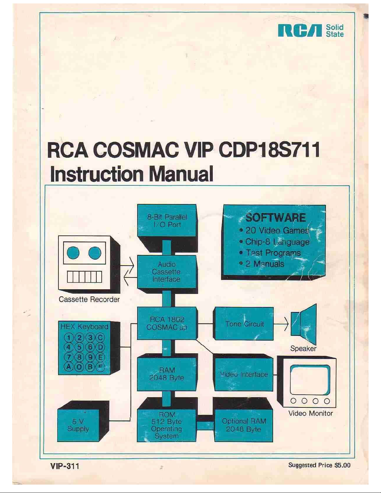
on the screen as'an array of spots 64 wide by 32 high. A
white spot represents a I bit in RAM, while a dark (or off)
spot represents a 0 bit in RAM. Each spot position on th ' e
screen can be located by a pair of coordinates as shown in
Fig. 1.
The VX byte value specifies the number of horizontal
spot positions from the upper left corner of the display. The
VY byte value specifies the number of vertical spot
positions from the upper left corner of the display.
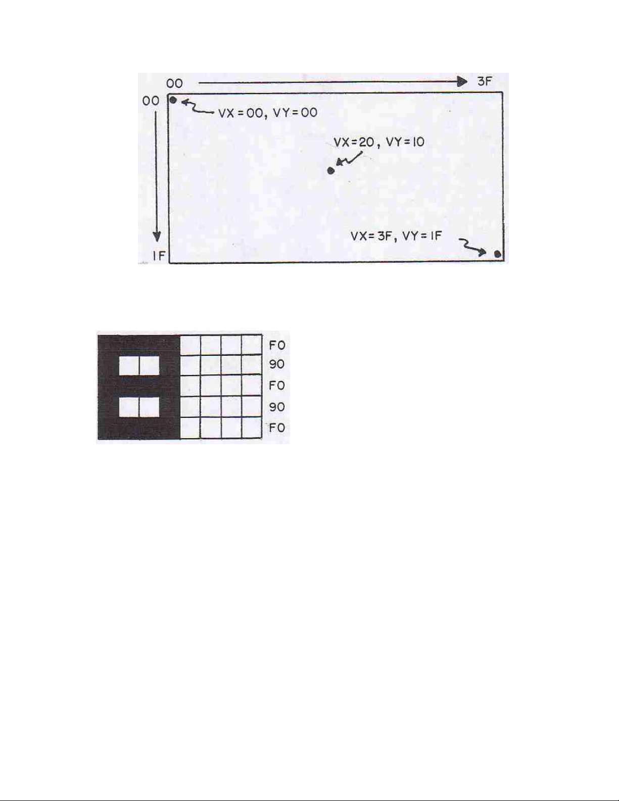
The DXYN instruction is used to show a pattern of spots
on the screen. Suppose we wanted to form the
Page 14
III. CHIP-8 Language Programming 15
Fig. 1 - Display screen coordinate structure.
pattern for the digit "8" on the screen. First we make pattern will be shown on the screen in the upper left
up a pattern of bits to form "8" as shown in Fig. 2. corner.
You can write a program to show the "8" pattern on
the screen as follows:
Fig. 2 - Patternof bitsjorming digit 8.
In this example we made the "8" pattern five spots
high by four spots wide. Patterns to be shown on the
screen using the DXYN instruction must always be one
byte wide and no more than fifteen bytes high. (Several
small patterns can be combined to form larger ones on
the screen when required). To the right of the."8" pattern
in Fig. 2 are the equivalent byte values in hex form. We
could now store this pattern as a list of five bytes at
RAM location 020A as follows:
020A F0
020B 90
020C F0
020D 90
020E F0
Suppose we now want to show this pattern in the
upper left corner of the screen. Well assign V I= VX and
V2=VY. Now we let VI=V2=00 and set I=020A. If we
now do a D125 instruction, the "8"
0200 A20A I=020A
0202 6100 V1=00
0204 6200 V2=00
0206 D125 SHOW 5MI@VlV2
0208 1208 GO 0208
020A F090
020C F090
020E F000
The first column of this program shows the memory
locations at which the instruction bytes in the second
column are stored. The third column indicates the
function performed by each instruction in shorthand
form. Only the bytes in the second column are actually
stored in memory.
With the CHIP-8 interpreter stored at 0000-OIFF, you
can load the above program in memory and run it. Set VI
and V2 to different values to relocate the “8" pattern on
the screen. The VX-VY coordinates always specify the
screen position of the upper lefthand bit of your pattern.
This bit can be either 0 or 1. The last digit of the DXYN
instruction specifies the height of your patterns or the
number of bytes in your pattern list.
When a pattern is displayed, it is compared with any
pattern already on the screen. If a 1 bit in your ,pattern
matches a I bit already on the screen, then a 0 bit will be
it
shown at this spot position and VF will be set 1,6
value
of 01. You can test VF following a DXTN instruction to
determine if your pattern
Page 15

16
0202 A300
0300
RCA COSMAC VIP Instruction Manual
touched any part of a previously displayed pattern. This
feature permits programming video games which require
knowing if one moving pattern touches or hits another
pattern.
Because trying to display two I spots at the same
position on the screen results in a 0 spot, you can use the
DXYN instruction to erase a previously displayed
pattern by displaying it a second time in the same
position. (The entire screen can be erased with a single
00E0 instruction.) The following program shows the "8"
pattern, shows it again to erase it, and then changes VX
and VY coordinates to create a moving pattern:
0200 A210 I=0210
0202 6100 V1=00
0204 6200 V2=00
0206 D125 SHOW 5MI@VlV2
0208 D125 SHOW 5MI@VlV2
020A 7101 V1+01
020C 7201 V2+01
020E 1206 GO 0206
0210 F090
0212 F090
0214 F000
0218 F229
021A D455
021C 6603
021E F618
0220 6620
0222 F615
0224 F607
0226 3600
0228 1224
022A 7301
022C 00E0
022E 1202
This program continuously increments V3, converts it to
decimal form, and displays it on the screen.
The FX0A instruction waits for a hex key to he
pressed, VX is then set to the value of the pressed key,
and program execution continues when the key is
released. (If key 3 is pressed, VX=03). A tone is heard
while the key is pressed. This instruction is used to wait
for keyboard input.
I =V2 (LSDP)
SHOW 5MI@V4V5
V6=03
TONE=V6
V6=20
TIME=V6
V6=TIME
SKIP;V6 EQ 00
GO 0224
V3+01
ERASE
GO 0202
Applying CHIP-8
The "8" pattern byte list was moved to 0210 to make
room for the other instructions. Try changing the values
that VI and V2 are incremented by for different
movement speeds and angles. A delay could be inserted
between the two DXYN instructions for slower motion.
The FX29 instruction sets I to the RAM address of a
five-byte pattern representing the least significant hex
digit of VX. If VX =07, then I would be set to the
address of a "7" pattern which could then be shown on
the screen with a DXYN instruction. N should
always be 5 for these built-in hex-digit patterns. 4.
Appendix C shows the format for these standard hex
patterns. The following program illustrates the use of
the FX29 and FX33 instructions:
0200 6300 V3=00
I=
0204 F333
0206 F265
0208 6400
020A 6500
020C F029
020E D455
0210 7405
0212 F129
0214 D455
0216 7405
MI=V3 (3DD)
VO:V2=MI
V4=00
V5=00
I =VO (LSDP)
SHOW 5MI@V4V5
V4+05
I=Vl(LSDP)
SHOW 5MI@V4V5
V4+05
You should now be able to write some simple CHIP-8
programs of your own. Here are some things to try:
1. Wait for a key to be pressed and show it on the
display in decimal form.
Show an 8-bit by 8-bit square on the screen and
2.
make it move left or right when keys 4 or 6 are held
down.
Show an 8-bit square on the screen. Make it move
randomly around the screen.
Show a single bit and make it move randomly
around the screen leaving a trail.
Program a simple number game. Show 100
(decimal) on the screen. Take turns with another
player. On each turn you can subtract 1-9 from the
number by pressing key 1-9. The first player to
reach 000 wins. The game is more interesting if you
are only allowed to press a key which is
horizontally or vertically adjacent to the last key
pressed.
If you are unsure of the operation of any CHIP-8
instruction, just write a short program using it. This step
should clear up any questions regarding its operation. In
your CHIP-8 programs be careful not to write into
memory locations 0000-01FF or you will
Page 16

111. CHIP-8 Language Programming
CAPTURE
ly
ified ti
17
lose the CHIP-8 interpreter and will have to reload it.
You can insert stopping points in your program for
debugging purposes. Suppose you want to stop and
examine variables when your program reaches the
instruction at 0260. Just write a 1260 instruction at
location 0260. Flip RUN down and use operating system
mode A to examine variables V0-VF. The memory map
in Appendix C shows where you can find them.
After the above practice you are ready to design more
sophisticated CHIP-8 programs. Always prepare a
flowchart before actually writing a program. The last
352 bytes of on-card RAM are used for variables and
display refresh. In a 2048-byte RAM system you can use
locations 0200-069F for your programs. This area is
enough for 592 CHIP-8 instructions (1184 bytes). In a
4096-byte RAM system you can use locations
0200-0E8F. This area is equal to 1608-CHIP-8
instructions (3216 bytes).
Some Program Ideas
Here are a few ideas for programs to write using the
CHIP-8 language:
9. LUNAR LANDING - Program a graphic lunar
landing game.
10. COLLIDE - Try to maneuver a spot from one
edge of the screen to the other without hitting
randomly moving obstacles.
Il.
moving spots within a spec
- Try to chase and catch random
me limit.
12. LEARNING EXPERIENCES - Program graphic
hand and eye coordination exercises for young
children or those with learning disabilities.
13. NUMBER RECOGNITION - Show groups of
objects or spots on the screen. Young child must
press key representing number of objects shown
to score.
WALL BALL - Program a wall-ball-type paddle
game for one player.
15. FOOTBALL - Each player enters his play via the
hex keyboard and the computer moves the ball on
the screen.
1. INTOXICATION TESTER - Display a six digit
16. BLACKJACK - Play "21" against the com
random number on the screen for several seconds.
You must remember this number and enter it from
the keyboard within ten seconds after the screen
17. HOLIDAY DISPLAYS - Design custom,
goes blank to prove that you're sober and score.
2. NUMBER BASE QUIZ - Display numbers in 18.
binary or octal on the screen. You must enter
their decimal equivalent to score points.
3. DICE - Push any key to simulate rolling dice
displayed on the screen.
19. TURING MACHINE - Simulate a simplifed
4. PUPPETS - Show large face on the screen. Let
small children move mouth and roll eyes by 20.
pushing keys.
BUSY BOX - Let small children push keys to 21.
r
make different object appear on the screen,
move, and make sounds.
22. NIM - Program Nim with groups of spots
6. SHUFFLEBOARD - Simulate shuffleboard
type games on the screen.
23. BLOCK PUZZLES - You can simulate a variety
7. COMPUTER ART - Design new programs to
generate pleasing geometric moving patterns on
the screen.
24. BOMBS AWAY - Show a moving ship at the
8. INVISIBLE MAZE - Try to move a spot
through an invisible maze. Tones indicate when
you bump into a wall.
puter dealer.
animated displays for birthdays, Halloween,
Christmas, etc.
METRIC CONVERSION - Help children learn
metric by showing lengths on screen in inches and
requiring centimeter equivalent to be entered to
score.
Turing machine on the screen.
TIMER - Use the computer to time chess games,
etc.
HEXAPAWN - Program Hexapawn so that the
computer learns to play a perfect game.
shown on the screen.
of sliding block-type puzzles on the screen.
bottom of the screen. Try to hit the ship by
releasing bombs from a moving plane at the top of
the screen.
Page 17

18
RCA COSMAC VIP Instruction Manual
25. PROGRAMMED SPOT - Introduce children to
programming concepts by letting them
preprogram the movements of a spot or object on
the screen.
The next section will discuss machine language
programming. You can even combine machine language
subroutines with CHIP-8 programs if desired.
Page 18

IV. Machine Language Programming
19
VIP Machine Coding
For a complete description of machine language
instructions, refer to the User Manual for the CDP1802
COSMAC Microprocessor MPM201A. Your
COSMAC VIP computer incorporates the following
special machine-language input and output instructions:
CODE OPERATION
69
6B
61
62
63
64
Operating System. It can also be used in expanded
systems if desired. Instructions 65, 66, 67, 6A, 6C, 6D,
6E, and 6F are also available for use in expanded
systems.
The External Flag lines are used as follows:
FLAG
Turn display on (Bus -> MX,D)
Input port byte + MX,D (Optional)
Turn display off (MX -> Bus,RX+1)
MX(LSD) -> Hex keyboard latch,
RX+1
MX -> Output port, RX+1 (Optional)
MX -> Bus,RX+l
One 64 instruction is always executed by the
USE
The latched Q line output performs several functions
in the COSMAC VIP system. When set, it holds the Q
light on and generates a continuous speaker tone. Ile Q
line is also used for serial output data to a cassette
recorder. You can use the Q output line as a control
signal in an expanded system if you avoid conflicts with
its normal functions.
You can store a machine language program starting at
location 0000. It will be executed when you flip the
RUN switch up. Initially P=0, X=0, R0=0000, Q=0, and
R1=0XFF, where 0X= last page of on-card RAM. (0X =
07 in 2048-byte RAM system). The operating system
uses the last 84 bytes of on-card RAM. You should
avoid using these last 84 RAM bytes when writing
machine language programs. With a 2048-byte RAM,
locations 07AC-07FF would be reserved for use by the
operating system. Note that Rl initially contains the
address of the last on-card RAM byte. Your machine
language program can use Rl to determine the amount of
RAM in your system when required.
Putting Machine Coding and
CHIP-8 Language Together
EF1
EF2
EF3
EF4
EF4 can be used for system expansion. EF3 can also
be used in expanded systems if no key will be depressed
at the same time that an external device is using EF3.
EF1 can only be used by an external device when the
display is turned off. EF2 should not be used in
expanded systems.
Generated by the video interface
(CDPI861)
Serial data from cassette player
Hex key pressed signal
Not used in basic system
The operating system and the CHIP-8 language
interpreter use a video display format that is 64 bits wide
by 32 bits high. This 256-byte display can easily be
modified by writing your own video refresh interrupt
routine as explained in the CDP1861 data sheet provided
in Appendix G. Display formats up to 64 bits wide by
128 bits high are possible with no hardware
modification. The 4096-bit picture program in Appendix
D uses a machine language refresh interrupt routine that
provides a format 64 bits wide by 64 bits high.
Page 19

20
RCA COSMAC VIP Instruction Manual
The CHIP-8 language described in the previous
section, permits machine language subroutines to be
called with a 0MMM instruction. A D4 machine
language instruction at the end of the machine language
subroutine returns control to the CHIP-8 instruction
following the 0MMM instruction. In Appendix C, the
CDP1802 register use for the CHIP8 language is
provided. R5 is used as the CHIP-8 program counter.
When you call a machine language subroutine with a
0MMM instruction, R5 will be addressing the CHIP-8
instruction following the 0MMM. The machine language
subroutine could retrieve the next two CHIP-8 program
bytes as parameters by addressing with R5 and
incrementing it by 2 before returning control to the
CHIP-8 program with a D4 instruction. RC, RD, RE, and
RF are available for use in machine language
subroutines. RA is the CHIP-8 memory pointer (1).
Changing the high-order byte of RB will cause any
desired RAM page to be displayed. R3 is the machine
language subroutine program counter.
CHIP-8 uses the operating system refresh interrupt
routine contained in ROM for display. You can use this
ROM interrupt routine for 256-byte display in your own
machine language programs. First initialize R1 to 8146
and R2 as a stack pointer before turning on the video
interface with a 69 instruction. Set the desired display
page into RB.1. This interrupt routine uses R0 as the
display refresh pointer and modifies RB.0. R8.1 and
R8.0 are decremented by 1 during each interrupt unless
they are equal to 00. Interrupts occur 60 times per second
when the video interface is turned on. This rate is
controlled by a crystal clock so that R8.0 and R8.1 can
be used as real-time clocks when needed. -
While the video interface is turned on, you should not
use any of the 3-machine-cycle CDP1802 instructions
(except those used for sync in the refresh interrupt
routine itself). If you are not using the video interface,
then you can use the CDP1802 3-cycle instructions in
your machine language programs. When you initiate a
machine language program at 0000 by flipping RUN up,
the video interface will be off. You must turn it on with a
69 instruction to use the COSMAC VIP graphic display
capability.
Machine Language
Programming Summed Up
In summary, COSMAC VIP provides you with an
easy-to-use language called CHIP-8. You can insert
machine language subroutines in CHIP-8 programs for
greater flexibility or expanded I/0 capability. You can
write complete machine language programs to fully
utilize CDP1802 capabilities. The operating svstem
facilitates debugging machine language programs by
permitting you to examine general registers R3-RF. (See
operating system register table in Appendix B).
Advanced programmers can even develop their own,
interpretive language tailored to special requirements.
Direct execution of machine language code starting at
location 0000 together with the expansion interface
permits the COSMAC VIP system to be used as a
low-cost development system as well as a personal
recreational or educational computer.
Page 20

V. Logic Description
21
A complete set of logic diagrams is provided in
Appendix E. Power requirements for a system with 2048
bytes of RAM is 5 V DC at 350 mA. If you wish to
expand the system you can use your own higher current
power supply.
This system is designed around the CDP1802
microprocessor Wfl. Refer to the CDP1802 data sheet
and User Manual for the CDPI802 COSMAC
Microprocessor MPM-201A for a complete description
of its operation. The CDP1802 requires a square-wave
clock input at pin 1 for operation. This system uses a
1.7609-MHz clock. One half of U3 is connected as a
free-running crystal-controlled oscillator. A
3.52180-MHz crystal is used in this circuit. The output of
this 3.52180-MHz oscillator is then divided by 2 using
U4 to provide the 1.7609MHz input clock for the
CDP1802. Because each CDP1802 machine cycle equals
8 clock cycles, each machine cycle is about 4.54 us in
duration. TPA and TPB are timing pulses generated once
each machine cycle by the CDP 1802 microprocessor.
How Memory Is Addressed
operating system program which uses a 64 instruction to
generate an N2 pulse. This-N2 pulse sets U6A so it no
longer holds U6B in its set state. From this point on, the
selection,of RAM or ROM locations is controlled by the
most significant address bit latched into U6B each cycle
by TPA.
U8 latches an additional 4 address bits to provide the
1-9-bit address required in a 4096-byte RAM system.
U9A decodes 2 of these address bits into 4 lines which
are used to select up to four 1024-byte RAM sections.
Each 1024-byte section of RAM consists of two 4 x
1024-bit RAM IC's (U16-U23 in Fig. E-4). Only the first
two sections of RAM (U16-U19) are used in a 2048-byte
system. U9B in Fig. E-2 is wired as a simple gate that
inhibits selecting any section of RAM when either the
ROM is selected or a positive RAM inhibit signal is
generated on pin 19 of the expansion interface by
external circuits.
Memory read (MRD) and write (MWR) signals are
supplied to the RAM at appropriate times by the
CDP1802. Data is transferred between memory,
CDP1802, input, or output via an 8-bit data bus. Pull-up
resistors are provided on this bus for compatibility with
TTL signal swings provided by some RAMs.
A debounced RUN level goes high when the RUN
switch is flipped up. This signal causes the CDP1802 to
begin fetching instructions from memory. When the
RUN switch is down, the CDP1802 is held in a reset
state and U6A (in Fig. E-2) is reset. U6B is held set by
U6A. The CDP1802 starts fetching instructions from the
ROM (U10) at location 8000 since UOB is being held
set. The ROM contains the
How the Input/Output Works
Ull and U12 in Fig. E-3 are used to decode the
input/output instruction codes used in the system.
U13 provides the hex keyboard interface. This
interface permits a program to determine which key is
Page 21

RCA COSMAC VIP Instruction Manual
pressed. A 62 machine instruction causes the least
significant 4 bits of memory byte to be latched into U13.
These 4 bits are decoded to bring one of the 16 U13
output lines low. If the key that corresponds to this
output line is pressed, the CDPI802 EF3 input will go
low. The 4-bit codes latched into U13 correspond to the
equivalent key positions. After the program send8 a 4-bit
code to U13, it subsequently examines the EF3 line to
see if the key corresponding to this code is pressed or
not. In this manner, a program can determine when any
specific key is pressed or can sequentially scan all keys
while waiting for any one to be pressed. Key debounce
delays must be provided in the program when required.
A program can also cause a speaker tone to occur when a
key is pressed. Only one key at a time should be pressed
with this method of interfacing the keyboard.
U15 generates an audible tone when pin 4 is high. The
output on pin 3 drives a small speaker. The 10 ohm
resistor R48 in series with the speaker output can be
raised in value to lower the volume if desired. The
CDP1802 latched Q-line output drives the tone generator
and also turns on the Q light. Q can be set high (1) or low
(0) by machine language instructions. The RC network
connected to pins 2, 6, and 7 of U15 determines the
frequency of the tone. You can increase or decrease the
value of R to adjust this frequency to suit your taste.
into 5-volt pulses by U14B. The output of U14B is
connected to the CDP1802 EF2 input line. The operating
system reads tape data by examining the timing of the
transitions on the EF2 input line. Cassette read and
record timing is derived from the crystal-controlled clock
so that no adjustments are necessary.
Video output is provided by the unique CDP1861
video display interface IC (U2 in Fig. E-1). Refer to the
CDP1861 data sheet. in Appendix G for a description of
its operation. This chip provides one of the lowest cost
and most useful display interface capabilities available
for any microcomputer. The values of the resistors RI
and R4 in Fig. E-1 of Appendix E connected to output
pins 6 and 7 of U2 can be adjusted for best results with
your video display. 61 and 69 machine language
instructions are used to generate the required on and off
pulses for U2. The down position of the RUN switch
resets the internal U2 circuits. When a program is
initiated, by flipping RUN up, U2 will remain off until a
69 instruction is executed. No CDP1802 interrupt or
DMA requests are generated by U2 until it is turned on
by a 69 instruction. U I and U2 are both driven by the
same clock. They must remain in sync to provide proper
operation of the display.
Q is also shaped by U14A in Fig. E-3 to form a signal
suitable for recording on an audio cassette. Audio
cassette recorders can't cope with square waves. Tle
divider on the output of U 14A reduces the signal to
about 50 mV which is suitable for the microphone input
of most recorders. During recording, the operating
system program in ROM converts memory bytes into bit
serial form and transmits them to the recorder via the Q
line. See the cassette data test page of Appendix A for
the cassette data code used.
In playback, bit serial data from the cassette drives the
tape light. The serial data is amplified and shaped
In general, the logic of this system has been kept
simple and straight-forward by the use of software to
replace hardware. This design not only yields a low cost
system, but one that should prove extremely reliable
because of the reduced number of components that can
cause failures. This system will not become obsolete for
a long time. RAM, ROM, and microprocessor are all
state-of-the-art devices and not obsolescent types that are
about to be replaced by better ones. The cassette and
video interfaces are optimum for long life. Also designed
into the system are full expansion capability for added
RAM, ROM, input, output, and full color graphics.
Page 22

V1. Expansion Considerations and
Connections
23
COSMAC VIP
The
self-contained graphic system for home use. Enough
RAM and input/output features are provided for years of
computer fun without adding anything to your system. If,
however, you do want to expand your system, a variety
of features have been included to make expansion as
easy and inexpensive as possible. You can easily
increase RAM to
to your PC card. Use the same type or a compatible type
of RAM as used for
have to add a higher-current power supply when
expanding RAM.
4096
was designed primarily as a
bytes by adding
U16-U19. You
may, however,
U20-U23
Using the Byte
Input/Output
First, you may wish to add some external computer-controlled devices such as relays, input sensing
switches, or even a low-cost printer. The printer will
require an 8-bit parallel input or output port and some
"hand-shaking" signals. One parallel input port and one
parallel output port are available on the PC card as
shown in Fig. E-5 in Appendix E. These ports are
provided by
the associated resistors and two
input/output port connection pads
back right edge of the PC card are connected to a
standard 44-pin card socket on the COSMAC VIP board.
You can plug your external circuits or devices into this
socket. Table II gives the input/output port terminal
connections.
U24, U25, U26,
IN914
and U27 along with
diodes. The 22
(A-Z)
along the
buffered Q output line (W) can be used as an output
strobe for transferring the latched output byte to an
external device such as a printer. The EF3 (X) and EF4
(L) input fines can be used to indicate the status of an
external device. Don't forget that EF3 is shared with the
hex keyboard.
Table 11 - Input/Output Port Terminal Connections
(See Fig. E-5, Appendix E)
Pin Signal Description
The 8 buffered output signals
(M,N,P,R,S,T,U,V)
TTL
loads. A 63 machine language instruction will
latch a memory byte into
output lines can be used to drive individual relay driver
circuits, power amplifiers, lights, battery motor drivers,
etc. The
will each drive up to
U24
for output. The 8 latched
2
Page 23

24
S
iple inp
ing devi
CD4515 IC
I
RCA COSMAC VIP Instruction Manual
A single photocell input could be provided via the
buffered EF4 line. You can attach the photocell
directly between the L and Z pads. Experimentally
adjust the pull-up resistor on pad L for best
operation. No photocell amplifier should be required
to drive the COS/MOS input. An, externally supplied
positive pulse- on. Pins 2_and 14 of U25,can be used as
an input,byte- strobe when yow want to latch an input
byte into U25. A 68 can be used to store
this input byte in RAM.
Using the Expansion
Interface
The 44-pin card socket for the expansion interface
pads along the back left edge of the PC board permits
extensive expansion. If you expand beyond the
capabilities of the power converter provided with the
VIP, you will, of course, have to provide your own power
supply. Output signals should only drive COS/MOS
loads, and must be externally buffered with a. CD4050
or CD4049 IC to drive TTL loads. Keep any wires
connected to the expansion pad signals as short as
possible. Excessive stray capacitance on these signal
lines can interfere with proper operation of the computer.
Input signals should also be buffered with COS/MOS
circuits. Refer to the. machine language programming
section (Section IV) and the logic diagrams (Appendix E)
to avoid conflicts with normal COSMAC VIP use of
these signals. The external option terminal connections
are given in Table III.
also latch high-order address bits to select external
devices if desired. When using external circuits to
generate DMA requests, interrupt requests, or input flag
signals, isolate these signals with 1N914 diodes as shown
for EF3 and EF4 in the optional parallel input/ output
port logic. Refer to the User Manual for the CDPI802
COSMAC Microprocessor, MPM-201A, for specific
examples of input/output attachment techniques.
Some Expansion Ideas
The August and September 1976 issues of Popular
Electronics contain descriptions of a COSMAC ELF
microcomputer using the CDP1802. These articles
illustrate some input/output attachment techniques.
The following lists some things that with some
exercise of your ingenuity could be added to your system
at relatively low cost:
1. Manually operated photoelectric paper-tape strip
reader. Only requires a tape guide and 8
photocells.
2.
canning circuit for mult
sens
3. Full alphanumeric keyboard.
4. Low-cost printer.
ces using
ut lines from
.
You can latch up the required high order address bits
with the trailing edge of TPA when adding external
memory. You must provide a Positive level on pad 19 to
disable internal RAM when external RAM is addressed.
The operating system will always use the highest page of
internal (on-card) RAM, even when you add external
RAM.
If you wish to substitute an external ROM or
battery-powered COS/MOS RAM for U10, you can use
the signal on pad X to select it. Remove U10 when
substituting an external ROM. If you do use an external
ROM for your own operating system you may no longer
be able to use the CHIP-8 interpreter because it requires
some of the operating system subroutines.
The expansion interface pads provide access to all
CDP1802 signals so that you can add any desired
external circuits.
Only 5 out of the possible 14 CDP1802 input/output
instructions are used internally, so that you can externally
decode the N0, N1, and N2 lines and use them with MRD
to obtain the use of the remaining 9 input/output
instruction codes. You can
5. Multi-digit numeric display.
6. Calculator chip.
7. Individual photocells or switches.
8. Output relays to control solenoids, bells,
whistles, sirens, lights, or motors.
9. Sound-generating circuits that can be controlled
by program.
10. Analog-to-digital input circuits.
11.
Read-Only Memory for fixed program.
12. Digital-to-analog output circuits.
Alpha wave monitor input to control pictures on
13.
TV or output devices.
14. Temperature- or pressure-sensing devices.
15.
Computer terminal.
16.
A second hex keyboard for multi-player video
games.
Page 24

V1. Expansion Considerations and Connections .25
Table III - External Option Terminal Connections
(See Fig. E-2, Appendix E)
Pin Signal Description
Negative-going memory-write pulse Early
timing pulse for M address clocking, etc.
Memory address lines. High-order address byte
appears on these lines during TPA time.,
followed by low-order address byte
8-bit, 2-way tri-state data bus
Low for memory read machine cycles
Chip select for operating system
Optional power for external logic
CDP1802 clock output
Flag input lines #3 and #4
(Flag 3 also used for hex keyboard)
Crystal frequency
Flag input line #1
Low-order 3 bits of N during
6N instruction
Video spot output
Video sync output
Timing pulse for clocking memory byte out, etc.
State code bit (+5 V for SI /S3, GND for SO/S2)
Pulling to GND causes interrupt (22-KE2 input)
State code bit (+5 V for S2/S3, GND for SO/Sl)
Pull to GND for DMA-OUT cycles
Q flip-flop output line
Pull to GND for DMA-IN cycles
+5 V when running, GND when RUN switch down
Internal RAM-disable input
GND when RAM pages C, D, E, and F selected
Optional power for external logic (same as Y-Z)
I
Page 25

26
RCA COSMAC VIP Instruction Manual
Some possible applications for expanded systems
include:
1. Counting packages, parts, cars, or people via 9.
photocell or switch input.
2. Composing poetry or pictures with printer output.
3. Video target games using photocell light gun.
4. Monitor burglar alarm switches.
5. Monitor water level and temperature in fish
tank and regulate automatically.
6. Measure motor speed with photocell.
7. Monitor and control experiments in home,
school, or lab. Use video display for real time
bar graphs of multiple variables.
8. Provide a crystal-controlled, programmable
pulse generator, clock, or timer.
Provide a programmable sequencer for light
shows, advertising displays, holiday lighting, etc.
10. Automatic telephone dialer.
11. Model railroad controller.
12. Battery-operated toy or robot controller.
13. Detect tape-player tones and control slide
projector.
You will soon discover that the potential applications
of a computer such as the COSMAC VIP are only
limited by your imagination and the ability to develop
appropriate interface circuits.
Page 26

VIL Troubleshooting Hints
27
This section is aimed at helping you diagnose and fix
hardware problems should they occur. First, check all
IC's to make sure they are properly inserted in the PC
card. An IC inserted in the wrong direction can be
permanently damaged. Check that the +5 V DC supply
voltage ripple does not exceed 0.2 volt. Visually inspect
the PC card for solder shorts or bad solder joints. Try to
avoid zapping your PC card with static electricity
charges. Discharge youself, if necessary, by touching a
grounded object before touching any IC's or PC card
wiring.
No Sound
If everything works but you don't hear any sound
from the speaker you probably have a bad U15, bad
speaker, or bad connection. Flip RUN up with key C
down. Hold any key down and the Q light should come
on. Check the Q line if it doesn't. The Q line should be at
+5 V with a key held. If the Q light is on, but with no
tone, check U15 and your speaker connections.
No Display
If you get no display but do get operating system key
tones, check the video output signal. First, select the
operating system to make sure video should be present.
The video signal should be 0.5 volt peak to peak or
higher. You should see negative-going vertical and
horizontal sync pulses and positive-going video pulses.
The sync pulses should be about 25% of the total swing.
Check your display system and interconnections if you
have the video signal present. Make sure you are using
the correct high-impedance input setting, for example.
Other Problems
Using operating system mode 0, load bytes into RAM
using all 16 hex keys. If a key doesn't work or shows the
wrong value on the display screen, check the keyboard
and U13.
If everything except the cassette interface works,
check U14. Review the cassette recording guidelines in
Appendix A. Use the cassette phase and data test
procedures described in Appendix A to find out what's
wrong.
If you can run some programs but not others, you
may have a bad RAM bit. Load and use the memory test
program provided in Appendix A. Try changing RAM
chips, one at a time.
If nothing seems to work and you can't run the
operating system, check your power supply and PC card
wiring for shorts again. If everything still seems OK you
will have to start signal tracing.
Signal Tracing
Check the U3 oscillator output. If not present, replace
U3. If the 3.521280-MHz signal is present, check the U4
divider. Replace U4 if it isn't toggling. Make sure you
use a 7474 type. With RUN up, you should see TPA and
TPB pulses being generated at pins 33 and 34 of U1 If
they are not present, check the RUN level to make sure
the switch is working, then replace U1.
Check the output of U6B to make sure that the ROM
is initially selected when RUN is first flipped
Page 27

28
RCA COSMAC VIP Instruction Manual
up with key C down. With RUN up, check bus and
address lines to see if any look different from the others.
They will, of course, be at different levels or bouncing
around but you might spot something suspicious that
would indicate a short or open for one of these lines.
Try operating with only a 1024-byte RAM (U16 and
U17). Try the other two RAM chips in these sockets.
Check U5 inputs and outputs to verify that all stages are
inverting properly.
If you don't get a pulse at pin 10 of U2 when you flip
RUN up with key C down, U12 may he bad. This pulse
is a difficult pulse to see and you might have to
breadboard a latch or use a latching logic probe to catch
it. If you get the display on pulse at pin 10 of U2, you
should then see U2 output pulses on pins 2, 3, and 9. If
you don't, try replacing U2.
Last Resorts
As a last resort, try replacing Ul and the ROM. Check
the supply voltage at all chips. Examine the PC card for
hairline breaks in the printed conductors. Fill up
plated-through holes with solder to insure continuity.
Check all signals. They should swing between ground
and +4 or 5 volts. If you see a logic signal at some
intermediate voltage, like +1 or 2 volts, check the source
IC.
Once you get the operating system running, over 90%
of the hardware will be operating properly. There are no
critical adjustments to be made or maintained. All system
timing is controlled by the crystal clock. With reasonable
care your COSMAC VIP system should run for years
without any problems.
Page 28

Appendix A - Test and Operating Data
29
Byte Pattern for Displaying "COSMAC"
The following figure shows how the word "COSMAC" would be formed by spots (or bits) on the
display screen.
The following bytes when loaded into memory will cause the word "COSMAC" to be shown on
the display in a 2048-byte RAM system. Start pattern of bytes at location OFOO in a 4096-byte
system.
0700 F9 F3 E6 CF 9F 00 00 00
0708 81 12 07 C8 90 00 00 00
0710 81 13 E5 4F 90 00 00 00
0718 81 10 24 48 90 00 00 00
0720 F9 F3 E4 48 9F 00 00 00
0728 00 00 00 00 00 00 00 00
Beeper Program
This machine- language program flashes the Q light and beeps at a rate determined by the byte at
location 0002. Change this byte for faster or slower rates.
0000 7A F8 0F BF 2F 9F 3A 04
0008 31 00 7B 30 01 00 00 00
Page 29

30
Cassette Attachment Diagram
Cassette Phase Test
RCA COSMAC VIP Instruction Manual
For best results your cassette recorder should not
reverse the phase of an input signal on playback. When
playing back a tape recorded on another recorder, it
should not reverse the phase of the output signal. You
may have to reverse the internal head connections on
some cassette recorders to eliminate unwanted phase
reversals.
To check for phase reversals, load the machine
language test program, given below, into memory.
Test Program
0000 F8 04 AA 7B F8 0C FF 01
0008 3A 06 7A F8 0C FF 01 3A
0010 0D 2A 8A 3A 03 F8 60 FF
0018 01 3A 17 30 00 00 00 00
Signals
Run this program to generate a phase test signal on the
tape out line. Record one minute of this test signal, then
play it back and observe the cassette recorder output on a
scope. It should appear as shown in B or C below. Save
this tape to test new recorders on which you want to play
tapes you have recorded on a previously tested machine.
If the playback signal appears upside down from that
shown in B or C, you will have to reverse the internal
head connection leads on the out-of-phase recorder.
Page 30

Appendix A - Test and Operating Data
Cassette Data Test
Load the following machine language program into memory:
0000 90 B6 B3 F8 33 A6 F8 OA
0008 A3 D3 F8 6F AC F8 40 B9
0010 93 F6 DC 29 99 3A 10 F8
0018 10 A7 F8 08 A9 06 B7 F8
0020 80 FE DC 97 F6 B7 DC 29
0028 89 3A 23 17 87 F6 DC 30
0030 17 30 31 35 00 00 00 00
31
Rewind a blank cassette and put recorder into record
mode. Wait 10 seconds and flip RUN up to initiate the
program. The byte at location 0033 will be continuously
recorded on tape. Flip RUN down to stop recording after
a minute or so. You can play this tape to check the
signals shown below. You can also load the tape into
memory for testing purposes. Load 7 pages starting at
0100. You can use this tape to determine the proper
volume control setting for your recorder. You can change
the recorded byte at 0033 if desired. Bits on tape consist
of one cycle at 2 kHz for
"0" or one cycle at 0.8 kHz for "1". Data format is 4
seconds of continuous "0's" for sync followed by the
specified number of data bytes. Bytes always begin with
a "1" start bit (S) followed by 8 data bits (0-7), and end
with a parity bit (P). Odd byte parity is used in this code.
The waveforms below show how a 35 byte would appear
on tape. The operating system translates memory bytes to
bit serial output via the Q output line. Bit serial input
from tape is received via input flag 2 and translated into
parallel form for storage in memory by the operating
system software.
A-OUTPUT OF U14A
B-OUTPUT FROM CASSETTE (TAP IN PAD ON CARD)
C-OUTPUT OF U14B
* WAVEFORMS SHOWN FOR PANASONIC MODEL RO-413S RECORDER.
Page 31

32 RCA COSMAC VIP Instruction Manual
Cassette Recording Guidelines
1. Use high quality tape (Maxell UD or 19.
equivalent).
2. Use shortest tapes possible. You can shorten
tapes to several minutes in length if you enjoy 20.
splicing.
3. Keep heads and pinch rollers clean.
4. Keep heads aligned for tape interchangeability.
5. Avoid recording too close to beginning of tape.
6. Make sure cassette is properly seated in 22.
recorder.
If you have trouble with a cassette try others.
7
You can have a had spot on tape or a warped
cassette.
8. Highest setting of tone control is usually best.
9. Set recorder volume control so that TAPE light
glows steadily on playback. This setting should
be lower than highest-volume setting. Excessive
TAPE light flickering indicates a bad tape or
misaligned heads.
10. A dirty recorder volume control can cause tape
dropouts.
18. When recording give the page key a short tap to
start.
Use the last byte of a tape block as a program
identification and check code. It will appear on the
display screen after the tape is loaded.
When loading a cassette into memory, the tape
must contain as many pages as you specify to be
loaded. If you try to load 8 pages from a 7-page
tape the loading operation won't terminate
properly.
21. You may have to record with the EAR plug out
for some tape recorders.
Always use AC adaptor with recorder for best
results.
Memory Test Program
This machine language program should be loaded into
0000-007F. It checks RAM locations 0000-07FF (UI8
and U19) for proper data storage. Flip RUN up to start
test. Beeps sound during test. Entire 1024 byte section
of RAM being tested is shown on screen. Program stops
with tone on if a bad RAM bit is found. Error byte is at
007F. This byte should be 00 or FF for no error. For
example, if byte is 01 or FE then bit 0 was bad. The
error byte is also shown on the screen.
Make sure cassette connection plugs make good
11.
contact.
12. Rewind cassettes before removing them from
recorder.
13. Store cassettes in dust-proof containers.
14. Avoid exposing cassettes to heat or magnetic
fields.
15. Before recording, wind cassette to one end and
fully rewind.
16. Cassette recorders will give you problems once in
a while (they don't like certain cassettes, etc.). If
one gives you problems most of the time replace
it.
17. Make sure that MIKE plug is connected before
recording. You will hear a tone even if MIKE plug
is out. On most recorders the TAPE light will
glow while recording.
Set location 0020=00 and location 0023=80 to test
RAM locations 0080-03FF (U16 and U17).
0000 90 B1 B2 B3 F8 17 A3 D3
0008 42 70 22 78 22 52 C4 C4
0010 C4 94 80 91 AO 30 08 F8
0018 0A Al F8 7F A2 E2 69 F8
0020 04 B4 F8 00 A4 94 B7 84
0028 A7 7A E2 F8 00 A5 F8 FF
0030 A6 85 57 94 BA 84 AA 8A
0038 52 87 F3 3A 45 9A 52 97
0040 F3 3A 45 30 47 86 5A 1A
0048 9A 52 94 FC 04 F3 3A 37
0050 07 52 85 F3 3A 6C F8 FF
0058 A5 93 A6 31 60 7B 30 31
0060 17 97 52 94 FC 04 F3 3A
0068 29 7A 30 6A 7B 30 6D 00
0070 00 00 00 00 00 00 00 00
0078 00 00 00 00 00 00 00 00
Page 32

Appendix B - Operating System
33
Operating System Listing
The following shows the machine language code for
the ROM operating system. ROM is addressed at
8000 F8 80 B2 F8 08 A2 E2 D2
8008 64 00 62 0C F8 FF Al F8
8010 0F B1 F8 AA 51 01 FB AA
8018 32 22 91 FF 04 3B 22 B1
8020 30 12 36 28 90 A0 E0 D0
8028 El F8 00 73 81 FB AF 3A
8030 29 F8 D2 73 F8 9F 51 81
8038 A0 91 B0 F8 CF Al D0 73
8040 20 20 40 FF 01 20 50 FB
8048 82 3A 3E 92 B3 F8 51 A3
8050 D3 90 B2 BB BD F8 81 BI
8058 B4 B5 B7 BA BC F8 46 Al
8060 F8 AF A2 F8 DD A4 F8 C6
8068 A5 F8 BA A7 F8 Al AC E2
8070 69 DC D7 D7 D7 B6 D7 D7
8078 D7 A6 D4 DC BE 32 F4 FB
8080 0A 32 EF DC AE 22 61 9E
8088 FB 0B 32 C2 9E FB 0F 3A
8090 8F F8 6F AC F8 40 B9 93
8098 F6 DC 29 99 3A 97 F8 10
80A0 A7 F8 08 A9 46 B7 93 FE
80A8 DC 86 3A AD 2E 97 F6 B7
80B0 DC 29 89 3A AD 17 87 F6
80B8 DC BE 3A 9E DC 69 26 D4
80C0 30 C0 F8 83 AC F8 0A B9
80C8 DC 33 C5 29 99 3A C8 DC
80D0 3B CF F8 09 A9 A7 97 76
80D8 B7 29 DC 89 3A D6 87 F6
80E0 33 E3 7B 97 56 16 86 3A
80E8 CF 2E BE 3A CF 30 BD DC
80F0 16 D4 30 EF D7 D7 D7 56
80F8 D4 16 30 F4 00 00 00 00
<eom>
8000-81FF. This listing can be used to verify the
contents of the ROM if required.
8100 30 39 22 2A 3E 20 24 34
8108 26 28 2E 18 14 1C 10 12
8110 F0 80 F0 80 F0 80 80 80
8118 F0 50 70 50 F0 50 50 50
8120 F0 80 F0 10 F0 80 F0 90
8128 F0 90 F0 10 F0 10 F0 90
8130 F0 90 90 90 F0 10 10 10
8138 10 60 20 20 20 70 A0 A0
8140 F0 20 20 7A 42 70 22 78
8148 22 52 C4 19 F8 00 A0 9B
8150 B0 E2 E2 80 E2 E2 20 A0
8158 E2 20 A0 E2 20 A0 3C 53
8160 98 32 67 AB 2B 8B B8 88
8168 32 43 7B 28 30 44 D3 F8
8170 0A 3B 76 F8 20 17 7B BF
8178 FF 01 3A 78 39 6E 7A 9F
8180 30 78 D3 F8 10 3D 85 3D
8188 8F FF 01 3A 87 17 9C FE
8190 35 90 30 82 D3 E2 9C AF
8198 2F 22 8F 52 62 E2 E2 3E
81A0 98 F8 04 A8 88 3A A4 F8
81A8 04 A8 36 A7 88 31 AA 8F
81B0 FA 0F 52 30 94 00 00 00
81B8 00 D3 DC FE FE FE FE AE
81C0 DC BE F1 30 B9 D4 AA 0A
81C8 AA F8 05 AF 4A 5D 8D FC
81D0 08 AD 2F 8F 3A CC 8D FC
81D8 D9 AD 30 C5 D3 22 06 73
81E0 86 73 96 52 F8 06 AE F8
81E8 D8 AD 02 F6 F6 F6 F6 D5
81F0 42 FA 0F D5 BE F6 AE 32
81F8 DC 3B EA 1D 1D 30 EA 01
<eom>
Page 33

34
Operating System Register Table
Memory Register Memory Register
Address Byte Address Byte,
0XB0 0XC0
0XB1 0XC1
0XB2 0XC2
0XB3 R3.0 0XC3 R3.1
0XB4 R4.0 0XC4 R4.1
0XB5 R5.0 0XC5 R5.1
0XB6 R6.0 0XC6 R6.1
0XB7 R7.0 0XC7 R7.1
0XB8 R&0 0XC8 R8.1
0XB9 R9.0 0XC9 R9.1
0XBA RA.0 0XCA RA.1
0XBB RB.0 0XCB RB.1
0XBC RC.0 0XCC RC.1
0XBD RD.0 0XCD RD.1
0XBE RE.0 0XCE RE.1
0XBF RF.0 0XCF RF.1
RCA COSMAC VIP Instruction Manual
0X = 07 for 2048-byte RAM
0X = 0B for 3072-byte RAM
0X = 0F for 4096-byte RAM
R5 = CHIP-8 language program counter
RA = CHIP-8 language I pointer
R3 = Machine Language Subroutine Program Counter
Operating System Summary
1. RUN up with key C pressed selects operating
system at 8000.
2. Enter four-digit address followed by mode digit: 5.
A MR (Memory Read)
0 MW (Memory Write)
B TR (Tape Read)
F TW (Tape Write)
3. CDP1802 microprocessor registers are stored as
shown in table above. They may be examined after
a program is run by using operating system mode A.
4. Mode 0 can be used to insert temporary stops in a
program for debugging purposes. Insert a
"branch-to-itself" instruction at the desired stopping
point.
The operating system uses the top 84 bytes of RAM
(0XAC-0XFF). Avoid using these byte locations in
your programs.
6. The operating system searches for and uses the top
(highest) 256-byte page of on-card RAM. When
RUN is flipped up to execute a program, beginning
at 0000, the following initial conditions exist:
P=0, Q=0, R0=0000, and R1 =0XFF where 0X highest
page of on-card RAM.
Page 34

Appendix C - CHIP-8 Interpreter
35
CHIP-8 Interpreter Listing
To use the CHIP-8 language you must first load the
following interpreter program into memory
0000 91 BB FF 01 B2 B6 F8 CF
0008 A2 F8 81 B1 F8 46 Al 90
0010 B4 F8 1B A4 F8 01 B5 F8
0018 FC A5 D4 96 B7 E2 94 BC
0020 45 AF F6 F6 F6 F6 32 44
0028 F9 50 AC 8F FA 0F F9 F0
0030 A6 05 F6 F6 F6 F6 F9 F0
0038 A7 4C B3 8C FC 0F AC 0C
0040 A3 D3 30 1B 8F FA 0F B3
0048 45 30
0050 00 01 01 01 01 01 01 01
0058 01 01 01 01 01 00 01 01
0060 00 7C 75 83 88 95 B4 87
0068 BC 91 EB A4 D9 70 99 05
0070 06 FA 07 BE 06 FA 3F F6
0078 F6 F6 22 52 07 FA 1F FE
0080 FE FE F1 AC 9B BC 45 FA
0088 0F AD A7 F8 D0 A6 93 AF
0090 87 32 F3 27 4A BD 9E AE
0098 8E 32 A4 9D F6 BD 8F 76
00A0 AF 2E 30 98 9D 56 16 8F
00A8 56 16 30 8E 00 EC F8 D0
00B0 A6 93 A7 8D 32 D9 06 F2
00B8 2D 32 BE F8 01 A7 46 F3
00C0 5C 02 FB 07 32 D2 1C 06
00C8 F2 32 CE F8 01 A7 06 F3
00D0 5C 2C 16 8C FC 08 AC 3B
00D8 B3 F8 FF A6 87 56 12 D4
00E0 9B BF F8 FF AF 93 5F 8F
00E8 32 DF 2F 30 E5 00 42 B5
00F0 42 A5 D4 8D A7 87 32 AC
00F8 2A 27 30 F5 00 00 00 00
<e0m>
40 22 69 12 D4 00
locations 0000-0IFF (2 pages). This interpreter will
allow you to run the games in Appendix D or write your
own programs using the CHIP-8 instruction set
described in section III.
0100 00 00 00 00 00 45 A3 98
0108 56 D4 F8 81 BC F8 95 AC
0110 22 DC 12 56 D4 06 B8 D4
0118 06 A8 D4 64 0A 01 E6 8A
0120 F4 AA 3B 28 9A FC 01 BA
0128 D4 F8 81 BA 06 FA 0F AA
0130 0A AA D4 E6 06 BF 93 BE
0138 F8 1B AE 2A 1A F8 00 5A
0140 0E F5 3B 48 56 0A FC 01
0148 5A 30 40 4E F6 3B 3C 9F
0150 56 2A 2A D4 00 22 86 52
0158 F8 F0 A7 07 5A 87 F3 17
0160 1A 3A 5B 12 D4 22 86 52
0168 F8 F0 A7 0A 57 87 F3 17
0170 1A 3A 6B 12 D4 15 85 22
0178 73 95 52 25 45 A5 86 FA
0180 0F B5 D4 45 E6 F3 3A 82
0188 15 15 D4 45 E6 F3 3A 88
0190 D4 45 07 30 8C 45 07 30
0198 84 E6 62 26 45 A3 36 88
01A0 D4 3E 88 D4 F8 F0 A7 E7
0lA8 45 F4 A5 86 FA 0F 3B B2
01B0 FC 01 B5 D4 45 56 D4 45
01B8 E6 F4 56 D4 45 FA 0F 3A
01C0 C4 07 56 D4 AF 22 F8 D3
01C8 73 8F F9 F0 52 E6 07 D2
01D0 56 F8 FF A6 F8 00 7E 56
0lD8 D4 19 89 AE 93 BE 99 EE
01E0 F4 56 76 E6 F4 B9 56 45
01E8 F2 56 D4 45 AA 86 FA 0F
01F0 BA D4 00 00 00 00 00 00
01F8 00 00 00 00 00 E0 00 4B
<eom>
Page 35

36 RCA COSMAC VIP Instruction Manual
CHIP-8 Memory Map
CDP1802 Register Use for CHIP-8
Interpreter
R0 = DMA pointer (page 0X for display refresh)
R1 = INTERRUPT routine program counter
R2 = Stack pointer
R3 = INTERPRETER subroutine program counter
R4 = CALL subroutine program counter
R5 = CHIP-8 instruction program counter
R6 = VX pointer (R6.1 must not be changed)
R7 = VY pointer (available for machine-language subroutines)
R8 = Timers (R8.1 = timer, R8.0 = tone duration)
R9 = Random number (+1 in INTERRUPT routine)
RA = I pointer
RB = Display page pointer (RB.1 = 0X)
RC =Available
RD = Available
RE = Available
RF = Available
Page 36

Appendix C - CHIP-8 Interpreter 37
CHIP-8/Operating System Standard Digit Display Format
Page 37

CHIP-8 User Notes
.
.
RCA COSMAC VIP Instruction Manual
1 Do not use any of the CDP1802 three-cycle
machine language instructions in CHIP-8
programs.
2. CDP1802 R5 is used as the CHIP-8 instruction
counter. It will he addressing the byte following a
0MMM instruction for machine language
subroutines and can be used to pass 2-byte
parameters. Refer to the operating system register
table in Appendix B to examine this register during
CHIP-8 program debugging.
3. ...............................................................................
4....................................................................................
5. R7, RC, RD, RE, and RF can be used as
working registers in machine language
subroutines. Changing other registers can cause
the CHIP-8 interpreter to malfunction.
6.....................................................................................
7. Program bugs can destroy the CHIP-8 interpreter at locations 0000-01FF. If you suspect
that this has happened, reload the interpreter.
8. The CHIP-8 interpreter uses subroutines and
digit patterns contained in the operating system
ROM. If you modify this operating system, the
CHIP-8 interpreter should not be used.
Page 38

A
39
This Appendix contains program listings for twenty
video games. These games, which illustrate entertainment applications of COSMAC VIP, were
developed by Joe Weisbecker (games, 1 through
8), Joyce Weisbecker (games 9 and 10), Jef
Winsor (games 11, 12, and 13), Tom Chen
(games 14,15, and 16), and Phil Baltzer (games
17 through 20).
Game Title .....................................................
1. VIP Kaleidoscope ...........................................................
2. VIP Video Display Drawing Game .................................
3. VIP Wipe Off ..................................................................
4. VIP Space Intercept .......................................................
5. VIP 4096-Bit Picture .......................................................
6. VIP Figure Shooting at Moving Target ...........................
7. VIP Tick-Tack-Toe Game ...............................................
8. VIP Spooky Spot ............................................................
9. VIP Jackpot ....................................................................
10. VIP Snake Race ...........................................................
11. VIP Card Matching Game ............................................
12. VIP Armored Vehicle Clash .........................................
13. VIP Hi-Lo ......................................................................
14. VIP Hex Reflex..............................................................
15. VIP Dot-Dash ...............................................................
16. VIP A-Mazing ...............................................................
17. VIP Deduce ..................................................................
18. VIP Shooting Stars .......................................................
19. VIP Strike-9 ..................................................................
20. VIP Card Game (like the well-known acey-
In the listing for each game, the first column is the
memory location at which the instruction bytes in
the second column are stored. The comments in
the third column indicate the function of the
instruction byte. The comments are not stored in
memory.
The game titles are listed below:
Page 39

40
RCA COSMAC VIP Instruction Manual
1. VIP Kaleidoscope
This program uses the CHIP-8 INTERPRETER at
0000-01FF. Four spots appear in a group at the center of
the screen. Press keys 2, 4, 6, or 8 to create a pattern.
Keep your pattern smaller than 138 key depressions.
Push key 0 to terminate pattern
0200 6000 V0=00
0202 6380 V3=80
0204 611F V1=1F
0206 620F V2=0F
0208 2232 DO 0232
020A A200 I=0200
020C F31E I=I+V3
020E F00A V0=KEY
0210 F055 MI-V0:V0
0212 4000 SKIP;V0 NE 00
0214 121C GO 021C
0216 7301 V3+01
0218 3300 SKIP;V3 EQ 00
021A 1208 GO 0208
021C 6380 V3=80
021E A200 I=0200
0220 F31E I=I+V3
0222 F065 VO:VO=MI
0224 4000 SKIP;VO NE 00
0226 121C GO 021C
0228 7301 V3+01
022A 4300 SKIP;V3 NE 00
022C 121C GO 021C
022E 2232 DO 0232
0230 121E GO 021E
0232 4002 SKIP;V0 NE 02
0234 72FF V2+FF
0236 4004 SKIP;VO NE 04
0238 71FF VI+FF
023A 4006 SKIP;V0 NE 06
entry. Pushing key 0 causes your pattern to be
continuously repeated forming a fascinating, changing
kaleidoscope display on the screen. A "44444442220"
key sequence provides a very nice effect Experiment to
find other nice patterns. The subroutine at 0232-0274
causes your pattern to be duplicated in the four quadrants
of the screen.
023C 7101 V1+01
023E 4008 SKIP;V0 NE 08
0240 7201 V2+01
0242 A277 I=0277
0244 6AEO VA=E0
0246 8A12 VA=VA&Vl
0248 6B1F VB=1F
024A 81B2 VI=Vl&VB
024C 3AOO SKIP;VA EQ 00
024E 7201 V2+01
0250 6AFO VA=FO
0252 8A22 VA=VA&V2
0254 6BOF VB=OF
0256 8282 V2=V2&VB
0258 3AOO SKIP; VAEQ 00
025A 7101 V1+01
025C 6BIF VB=1F
025E 81B2 Vl=Vl&VB
0260 D121 SHOW 1MI@VlV2
0262 8A10 VA=Vl
0264 6B1F VB=1F
0266 8B25 VB=VB-V2
0268 DAB1 SHOW 1MI@VAVB
026A 6A3F VA=3F
026C 8A15 VA=VA-VI
026E DABI SHOW 1MI@VAVB
0270 8B20 VB=V2
0272 DAB1 SHOW 1MI@VAVB
0274 00EE RET
0276 0180
0278 0000
Page 40

Appendix D - Video Games
41
2. VIP Video Display Drawing Game
This program uses the CHIP-8 INTERPRETER at
0000-01FF. A flashing spot appears in the upper left
corner of the screen. You can move the spot by holding
key 2, 4, 6, or 8. Press key 5 and you can draw a picture
with the spot. Press key 0 and the spot can be moved
without drawing or used to erase a previously drawn
line. 0245-024E is a list of
0200 A245 I=0245
0202 F965 VO:V9=MI
0204 A24F I=024F
0206 0236 MLS@0236
0208 OOEO ERASE
020A F915 TIME-V9
020C FA07 VA=TIME
020E 3AOO SKIP;VA EQ 00
0210 120C GO 020C
0212 D121 SHOW 1MI@V1V2
0214 3FOO SKIP;VF EQ 00
0216 D121 SHOW 1MI@VIV2
0218 E3A1 SKIP;V3 NE KEY
021A 8030 VO=V3
021C E4AI SKIP;V4 NE KEY
O~U 8040 VO=V4
0220 4000 SK1P;VO NE 00
0222 123C GO 023C
0224 E5A1 SKIP;V5 NE KEY
0226 72FF V2+FF
initial values for VO-V9. In this program, locations
0300-03FF are used for the picture. After drawing a
picture, you can change M(0208) from OOEO to 120A.
Write locations 0000-03FF (4 pages) to tape to save your
picture. When you load these four pages back into
memory you will see your original picture. Changing the
OOEO instruction in the program to 120A prevents your
picture from being erased when the program is started.
0228 E6A1 SKIP;V6 NE KEY
022A 71FF V1+FF
022C E7AI S&IP;V7 NE KEY
022E 7101 V1+01
0230 E8A1 SKJP;V8 NE KEY
0232 7201 V2+01
0234 120A GO 020A
0236 OlF8
0238 03BB
023A E2D4
023C D121 SHOW 1MI@V1V2
023E 4FOO SKIP;VF NE 00
0240 D121 SHOW 1MI@V1V2
0242 1224 GO 0224
0244 0100
0246 0000
0248 0005
024A 0204
024C 0608
024E 0880
Page 41

Appendix E - Logic Diagrams
67
Fig. E-1 Microprocessor and Display Interface
Circuits
Fig. E-2 ROM Circuits and Expansion Interface
Fig. E-3 Keyboard, Decoding, Audio Oscillator,
and Cassette Interface Circuits
Fig. E-4 RAM Circuits
Fig. E-5 Power Supply Circuit and Byte
Input/Output Interface
Page 42

68
RCA COSMAC VIP Instruction Manual
Fig. E-1
- Microprocessor and Display Interface Circuits
Page 43

Appendix E - Logic Diagrams 69
Fig. E-2 - ROM Circuits and Expansion Interface
Page 44

70 RCA COSMAC VIP Instruction Manual
Fig. E-3 - Keyboard, Decoding, Audio Oscillator,
and Cassette Interface Circuits
Page 45

Appendix E - Logic Diagram's
71
Fig. E-4 - RAM Circuits
Page 46

72 RCA COSMAC VIP Instruction Manuel
Fig. E-5 - Power Supply Circuit and Byte Input/Output Interface
Page 47

72 RCA COSMAC VIP Instruction Manual
Fig. E-5 - Power Supply Circult and Byte Input/Output Interface
Page 48

Appendix F -
.
COSMAC V
Board Layout, Parts List, and Expansion Notes
73
1. Printed Circuit Board Layout
2
Parts List for RCA
IP CDP18S711
Page 49

74 , RCA COSMAC VIP Instruction Manual
Page 50

Page 51

Appendix F - Board Layout, Parts List, and Assembly Instructions
2. Parts List for RCA COSMAC VIP CDP18S711
Type Number Qty. Description
Integrated Circuits - Supplied
CDP1802 Ul 1 COSMAC Microprocessor
CDPI 861 U2 1 Video Interface
SN74L00N U3 1 Quad NAND Low Power
SN7474N U4 1 Dual D-Type Flip-Flop
CD4049 U5 1 Hex Inverting Buffer
CD4013 U6 1 Dual D-Type Flip-Flop
CD4011 U7 1 Quad 2-Input NAND Gate
CD4042 U8 1 Quad Clocked "D" Latch
CD4556 U9 1 Dual Binary 1 of 4 Decoder
CDPR566 U10 1 512 x 8-Bit Static ROM (Programmed CDP1832)
CD4051 Ull 1 Binary 1 of 8 Decoder
CD4028 U12 1 BCD-to-Decimal Decoder
CD4515 U13 1 4-Bit Latch/] of 16 Decoder
CA3401 U14 1 Quad Single-Supply Op-Amp
CA555CE U15 1 Timer
2114 or TMS4045 U16-U19 4 1 K x 4-Bit Static RAM
CD4508 U24,U25 2 Dual 4-Bit Latch
CD4050 U26,U27 2 Hex Buffer
Integrated Circuits - Optional
2114 or TMS4045 U20-U23 4 1 K x 4-Bit Static RAM
-76
Capacitors - Supplied
Cl,Cl0 2 4.7 uF 35 V Electrolytic
C2 1 100 uF 16 V Electrolytic
C3 1 0.0047 uF 50 V Poly Film (472)
C4,C5 2 0.47 uF 50 V
C6,C7,C13 3 0.0 1 uF 50 V Poly Film (103)
C8,C12 2 1 uF 50 V Electrolytic
C9 1 22 uF 16 V Electrolytic
C11 1 470 pF 500 V Disc
C14 1 33 pF ± 10% 1 kV
(Continued on next page)
Page 52

Page 53

76 RCA COSMAC VIP Instruction Manual
2. Parts List for RCA COSMAC VIP CDP18S711 (Continued)
Type Number Qty. Description
Resistors - Supplied (1 /4 W except as noted)
RI 1 3.3 K ohm
R3 R5 RIS
Rl6, R33 7 10 K ohm
R39, R40
R2, R17 2 1 K ohm
R6-RI4
R19, R20
R22-R30, R36 28 22 K ohm
R41-R47
R18, R21 2 100 ohm
R31, R32
R37, R38 470 ohm
R50
R34 1 100 K ohm
R35, R49 3 1 megohm
R52
R48 1 10 ohm 1/2 W
R51 1 4.7 K ohm
R4 1 200 ohm
Miscellaneous - Supplied
I N914 CR1 through 5 Diode
CR5
HP5082-4494 3 Red LED
1 3.521280 MHz Crystal
7 101 -S-D-V30-B Sl 1 SPDT Toggle Switch; C&K
E7807 1 Panel Dress Nut for Switch; C&K
18SO22 1 Printed Circuit Board
M-1651.0 1 Keyboard, Centralab
1 Cover, Thermoplastic
7 Rubber Feet
C931802 4 18-Pin IC Socket
C932402 1 24-Pin IC Socket
C934002 1 40-Pin IC Socket
CDP18S023 1 Power Supply, Regulated; 5 V dc, 600 mA; 110 V 50/60 Hz
6Cable Straps
1Speaker
JI,J2 2 44-Pin Connector
MPM-201 1 User Manual for the CDP1802 COSMAC Microprocessor
MPM-920 1 Instruction Summary for the CDP 1802 COSMAC Microprocessor
VIP-311 1 RCA COSMAC VIP Instruction Manual
Connectors, cables, hardware
Miscellaneous - Optional
LAD66A2CD 1 Heat Sink; IERC
2 4-40 1/4" Binder Hd. Machine Screws and Nuts
7805 U28 1 Voltage Regulator
Page 54

Page 55

Appendix F - Board Layout, Parts List, and Assembly Instructions 77
3. COSMAC VIP Expansion Notes
a. Soldering the PC Board
In the event you wish to make some changes or
add components requiring soldering, you should have
some experience building electronic kits. The PC
board pads are small and close together requiring
extra caution when soldering to avoid shorts or solder
bridges. Use a low-heat, small-tipped, grounded
soldering iron. Keep it clean. Use small gauge, rosin
core 60/40 solder. Preheat the connection and apply
just enough solder to "wet" the connection. Avoid
using excessive amounts of solder because it will flow
through the plated-through holes and form "blobs"
on the top of the card. Excessive or protracted heat
from the soldering iron can damage some of the
components.
b. Voltage Regulator Option
An unregulated 8-10 volt DC power supply can
be used with the COSMAC VIP card if desired. Cut
LK1 on the PC card. Add U28 (a 7805, 5-volt
regulator IC) to the card together with an appropriate
heat sink. Make sure the U28 lead pads on the PC DC
card don't touch the heat sink. Disconnect the +5 V
supply at the + V DC and GND pads and connect your
unregulated 8-10 V DC power supply to these pads.
This on-card regulator will handle up to I ampere of
current and is useful for system expansion. Do not use a
plastic cover for your PC card when this on-card
regulator option is used. Air How is needed to permit
the regulator to operate properly.
c. Additional 2048-Byte RAM Option
To increase your COSMAC VIP RAM to a total of
4096 bytes, add U20-U23 to the PC card by plugging
units into the four sockets provided. Measure the power
supply current to be sure it does not exceed the capacity
of the +5 V DC power pack supplied with the VIP (600
mA). If you require additional power supply current use
a regulated +5 V DC supply capable of supplying I
ampere or use an unregulated 8-10 V DC supply with
the voltage regulator option on the cards.
 Loading...