

Page 1
.
/
USER’
GUID
Table
of Contents ......................
Optional
Accessories..
First-Time Operation .................
Powering Your
Recording and Traveling Tips....2 1
Recording Features .................
Specifications ..........................
Playback ................................
)
1
Maintenance
Care
and
Trouble Checks .......................
Limited
Warranty.. ..................
Index
................
Camcorder..
.....
............
l........ 56.............................
.l
.l
.8
.16
.24
.43
.44
.50
.52
.55
S
E
Page 2

Please fill out the product registration card and return it immediately. Returning this
card allows us to contact you if needed.
Keep your sales receipt to obtain warranty parts and service and for proof of
purchase. Attach it here and record the serial and model numbers in case you ever
need them. The numbers are located on the bottom of your camcorder.
Model No: CC800
I
Serial No:
/
Purchase Date:
Purchased From:
SAFETY PRECAUTIONS
j
Your video camcorder’s AC adapter/charger will operate on
loo-240
j
volts AC, 50/60 Hz, and has a polarized plug. Because one blade of
the plug is wider than the other, the plug fits in the wall socket only
I
1
one way. Do not defeat the safety feature of this plug. If you need an
I
extension cord, use a polarized extension cord.
CAUTION:
TO PREVENT ELECTRIC SHOCK, MATCH WIDE BLADE OF
PLUG TO WIDE SLOT, FULLY INSERT.
ATTENTION: POUR
EvI’IER LES CHOCS ELECTRIQUES,
INTRODUIRE
LA LAME LA PLUS LARGE DE LA FICHE DANS LA BORNE
CORRESPONDANTE DE LA PRISE ET POUSSER JUSQU’AU FOND.
CAUTION:
TO REDUCE THE RISK OF ELECTRIC SHOCK, DO NOT
REMOVE THE COVER (OR BACK). NO USER-SERVICEABLE PARTS ARE
INSIDE. IF YOU SPILL LIQUID ON THE CAMCORDER OR
ADAPTER/CHARGER, DISCONNECT THE AC ADAPTER/CHARGER’S POWER
CORD TO PREVENT POSSIBLE FIRE OR SHOCK
HAZARD AND CONSULT
AUTHORIZED SERVICE PERSONNEL. MOISTURE CAN DAMAGE
INTERNAL PARTS. REFER ALL SERVICE TO AUTHORIZED RCA
CAMCORDER SERVICENTER PERSONNEL ONLY.
i
Page 3
SAFETY PRECAUTIONS
(continued)
CAUTION:
READ “IMPORTANT SAFETY INSTRUCTIONS FOR AC
ADAPTER/CHARGER”
ON THE NEXT PAGE
BEFORE USING THE AC
ADAPTER/CHARGER.
CAUTION:
MAINTAIN ELECTRICAL SAFETY. POWERLINE-OPERATED
EQUIPMENT OR ACCESSORIES CONNECTED TO THIS UNIT SHOULD BEAR
THE UL LISTING MARK OR, IF PURCHASED AND USED IN CANADA, THE
CSA CERTIFICATION MARK ON THE ACCESSORIES THEMSELVES AND
SHOULD NOT HAVE BEEN MODIFIED SO AS TO DEFEAT THE SAFETY
FEATURES. THIS WILL HELP AVOID ANY POTENTIAL HAZARD FROM
ELECTRIC SHOCK OR FIRE. IF IN DOUBT, CONTACT QUALIFIED SERVICE
PERSONNEL.
I
WARNING:
TO REDUCE THE RISK OF FIRE OR SHOCK HAZARD,
DO NOT EXPOSE CAMCORDER OR AC ADAPTER/
CHARGER TO RAIN OR MOISTURE.
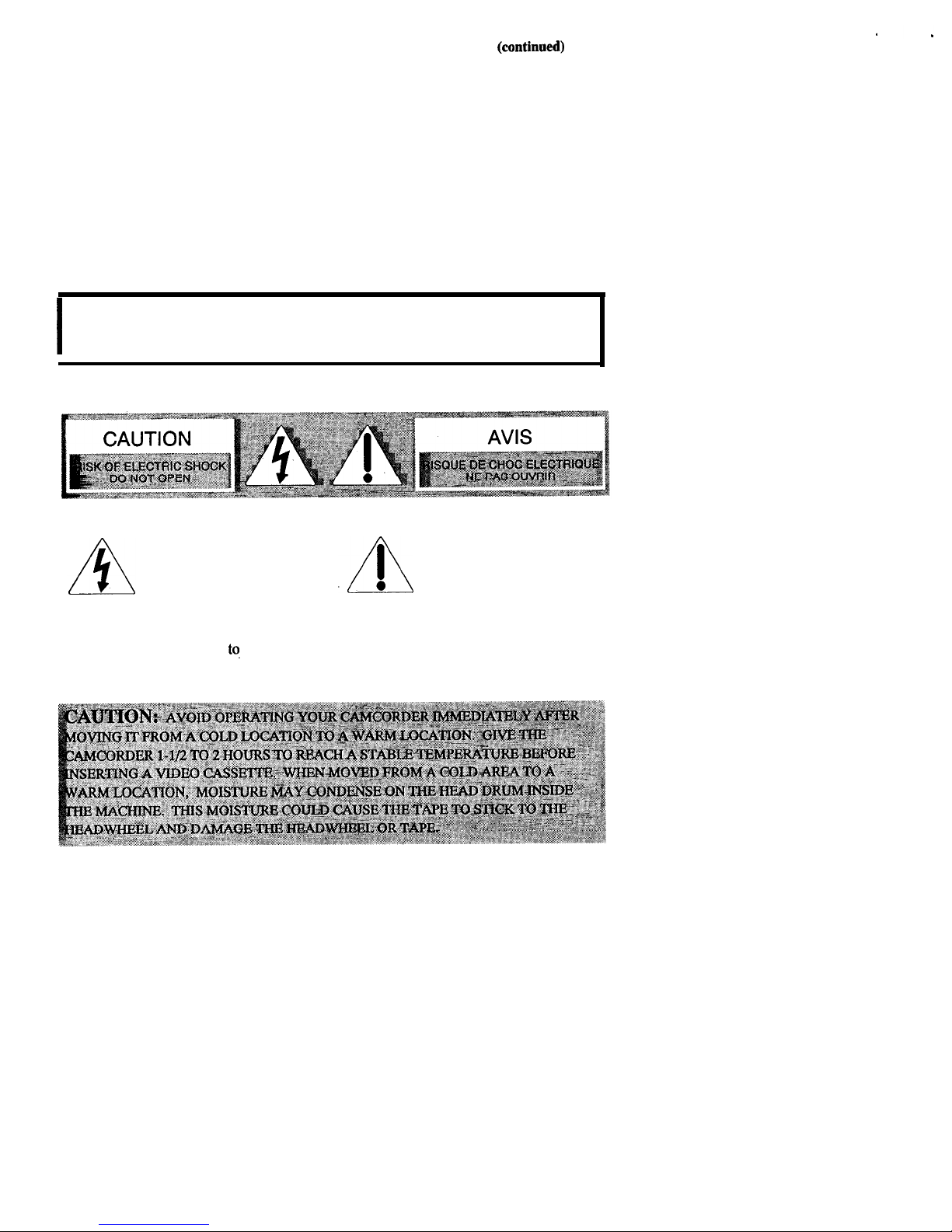
The symbol of a lightning
.A
An exclamation point
flash within. a triangle is
within a triangle is
intended to alert the user
intended to alert the user
to the presence of
l
to the presence of
uninsulated “dangerous voltage”’ within
the product’s enclosure and which may
be of sufficient magnitude
to.
constitute
a risk of electric shock.
important operating and maintenance
(service) instructions in the literature
accompanying the product.
ii
Page 4

Important Safety Instructions for AC Adapter/Charger
Before using the AC adapter/charger,
read all instructions and cautionary
markings on (1) AC adapter/charger,
(2) battery, and (3) product using battery.
Caution:
To reduce risk of injury,
charge only rechargeable batteries type
FB1260, or FB120. Other types of
batteries may burst causing personal
injury and damage.
Do not expose the adapter/charger to
moisture of any kind.
Use of an attachment not recommended
or sold by the battery charger
manufacturer may result in a risk of fire,
electric shock, or injury to persons.
To reduce risk of damage to electric plug
and cord, pull out the cord with the plug
rather than the cord when disconnecting
the adapter/charger from the wall outlet.
Make sure the cord is located so that it
will not be stepped on, tripped over, or
otherwise subjected to damage or stress.
Use of an improper extension cord could
result in a risk of fire and electric shock.
If an extension cord must be used, make
sure that:
1. Pins on the plug of the extension cord
are the same number, size, and shape
as those of the plug on the
adapter/charger.
2. Extension cord is properly wired and
in good electrical condition, and
3. Wire size below is met:
Minimum
Length of Extension
AWG Size
Cord (Feet)
18
Equal to or less
than 100
16
Equal to or less
than 150
Do not operate adapter/charger with a
damaged cord or plug. Replace it
immediately.
Do not operate adapter/charger if it has
received a sharp blow, been dropped, or
otherwise damaged in any way. Take it
to a qualified serviceman.
Do not disassemble adapter/charger.
Take it to an Authorized RCA
Camcorder
Se¢er
when service or
repair is required. Incorrect reassembly
may result in a risk of electric shock.
To reduce risk of electric shock, unplug
charger from outlet before attempting any
maintenance or cleaning.
Be sure to save these operating
instructions for future reference.
CAUTION:
FCC REGULATIONS STATE THAT ANY UNAUTHORIZED
CHANGES OR MODIFICATIONS TO THIS EQUIPMENT MAY VOID THE
USER’S AUTHORITY TO OPERATE IT.
CAUTION:
THE UNAUTHORIZED RECORDING OF TELEVISION
PROGRAMS AND OTHER MATERIALS MAY INFRINGE THE RIGHTS OF
OTHERS.
. . .
111
Page 5
IMPORTANT SAFEGUARDS
In addition to the careful attention
devoted to quality standards in the
manufacture of your product, safety
is a major factor in the design of
every instrument. However, safety is
your responsibility too.
These pages list important
information that will help to assure
your enjoyment and proper use of a
camcorder, adapter/charger, and
accessory equipment. Please read
them carefully before operating your
products.
Installation
1. Read and Follow
Instructions-
All the safety and
operating instructions should be read
before the product is
operated. Follow all
operating
instructions.
2. Retain Instructions-The
safety and
operating instructions should be
retained for future reference.
3. Heed
Warnings--Comply
with all
warnings on the product and in the
i
operating instructions.
4. Polarization-This
product is
equipped with a polarized altemating-
current line plug (a plug having one
blade wider than the other). This plug
will fit into the power outlet only one
way. This is a safety feature. If you
are unable to insert the plug fully into
the outlet, try reversing the plug. If
the plug still fails to fit, contact your
electrician to replace your obsolete
outlet. To prevent electric shock, do
5.
6.
7
,.
not use this polarized plug with an
extension cord, receptacle, or other
outlet unless the blades can be fully
inserted without blade exposure. If
you need an extension cord, use one
with a polarized plug.
Power Sources-This
product should
be operated only from the type of
power source indicated on the
marking label. If you are not sure of
the type of power supply to your
home, consult your dealer or local
power company. For products
intended to operate from battery
power, or other sources, refer to the
operating instructions.
Overloading-Do
not overload wall
outlets, extension cords, or integral
convenience receptacles as this can
result in a risk of fire or electric shock.
Overloaded AC outlets, extension
cords, frayed power cords, damaged
or cracked wire
insulation, and
broken plugs are
dangerous. They
may result in a
shock or fire
hazard.
Periodically examine the cord, and if
its appearance indicates damage or
deteriorated insulation, have it
replaced by your service technician.
Power-Cord
Protection-Power-
supply cords should be routed so that
they are not likely to be walked on or
pinched by items placed upon or
against them, paying particular
attention to cords at plugs,
convenience receptacles, and the point
where they exit from the product.
(continued on next page)
iv
Page 6

IMPOR’IIANT
SAFEGUARDS
(continued)
8. Ventilation--Slots and openings in
the products are provided for
ventilation to ensure reliable
operation of the product and to
protect them from overheating.
These openings must not be blocked
or covered. The openings should
never be blocked by placing the
product on a bed, sofa, rug, or other
similar surface. This product should
not be placed in a built-in
installation such as a bookcase or
rack unless proper ventilation is
provided or the product
manufacturer’s instructions have
been followed.
9. Attachments-Do not use
attachments unless recommended by
the product manufacturer as they
may cause hazards.
10. Water and Moisture--Do not use
this product near water-for
example, near a bath tub, wash bowl,
kitchen sink or laundry tub, in a wet
basement, or near a swimming pool
and the like.
11. Accessories-Do not place this
product on an unstable cart, stand,
tripod, bracket, or table. The
product may fall, causing serious
injury to a child or adult as well as
serious damage to the product. Use
this product only with a cart, stand,
tripod, bracket, or table
recommended by the manufacturer
or sold with the product. Any
mounting of the product should
follow the manufacturer’s
instructions and use a mounting
accessory recommended by the
manufacturer.
1lA
A product and cart combination
should be moved with care. Quick
stops, excessive force, and uneven
surfaces may cause the product and
cart combination to overturn.
(continued on next page)
V
Page 7

IMPORTANT SAFEGUARDS
(continued)
12. Outdoor Antenna Grounding-If
an outside antenna or cable system is
connected to the product, be sure the
antenna or cable system is grounded
so as to provide some protection
against voltage surges and built-up
static charges. Article 810 of the
National Electrical Code,
ANSVNFPA No. 70 (Section 54 of
Canadian Electrical Code, Part 1)
provides information with respect to
proper grounding of the mast and
supporting structure, grounding of
the lead-in wire to an antennadischarge unit, size of grounding
conductors, location of antennadischarge unit, connection to
grounding electrodes, and
requirements for the grounding
electrode. See example below as per
National Electrical Code,
ANSIJNFPA 70.
Example of Antenna Grounding
13.
Power Lines-Au outside antenna
system should not be located in the
vicinity of overhead power lines,
other electric light or power circuits,
or where it can fall into such power
lines or circuits. When installing an
outside antenna system, extreme
care should be taken to keep from
touching or approaching such power
lines or circuits as contact with them
might be fatal. Installing an outdoor
antenna can be hazardous and should
be left to a professional antenna
installer.
Use
14.
15.
Cleaning-Unplug this product
from the wall outlet before cleaning.
Do not use liquid cleaners or aerosol
cleaners. Use a damp cloth for
cleaning.
Object and Liquid
Entry-Never
push objects of any kind into this
product through openings as they
may touch dangerous voltage points
or “short-out” parts that could result
in a fire or electric shock. Never
spill liquid of any kind on the
product.
(continued on next page)
vi
Page 8

IMPORTANT SAE’EGUARDS
(continued)
16. Lightning-For
added protection
for this product during a lightning
storm, or when it is left unattended
and unused for long periods of time,
unplug it from the wall outlet and
disconnect the antenna or cable
system. This will prevent damage to
the product due to lightning and
power line surges.
Service
17. Servicing-Do not attempt to
service this product yourself as
opening or removing covers may
expose you to dangerous voltage or
other hazards. Refer all servicing to
qualified service personnel.
18. Conditions Requiring
Service-
Unplug this product from the wall
outlet and refer servicing to qualified
service personnel under the
following conditions.
A. When the power-supply cord or
plug is damaged.
B. If liquid has been spilled, or
objects have fallen into the
product.
C. If the product has been exposed to
rain or water.
vii
19.
20.
21.
22.
D. If the product does not operate
normally by following the
operating instructions. Adjust
only those controls that are
covered by the operating
instructions. Improper
adjustment of other controls may
result in damage and will often
require extensive work by a
qualified technician to restore the
product to its normal operation.
E.
If the product has been dropped in
any way.
F. When the product exhibits a
distinct change in
performance-
this indicates a need for service.
Replacement Parts-When
replacement parts are required, have
the service technician verify that the
replacements he uses have the same
safety characteristics as the original
parts. Use of replacements specified
by the product manufacturer can
prevent fire, electric shock, or other
hazards.
Safety Check-Upon completion of
any service or repairs to this product,
ask the service technician to perform
safety checks recommended by the
manufacturer to determine that the
product is in safe operating
condition.
Wall or Ceiling Mounting-The
product should be mounted to a wall
or ceiling only as recommended by
the manufacturer.
Heat-The
product should be
situated away from heat sources
such as radiators, heat registers,
stoves, or other products (including
amplifiers) that produce heat.
Page 9

Product Registration..
..........................
i
Safety Precautions
..........................
i-vii
Optional Accessories..
......................
l-7
l
Accessory Order Form..
...............
.5-7
First-Time Operation
...................
.8-15
PoweringYour Camcorder..
......
.16-20
Recording and Traveling Tips
........
.21
Video Cassettes..
..........................
.22-23
Features
l
Camera Edit
...................................
24
l
Quick Review..
..............................
.24
l
Tally Light
.....................................
24
l
Microphone
....................................
24
l
Flying Erase Head..
.......................
.24
l
Auto Head Cleaner..
......................
.24
l
Electronic Indexing..
.....................
.24
l
Electronic Viewfinder..
.................
.25
l
Viewfinder Displays..
...............
.26-27
l
Date and Time Displays
..........
.28-31
l
Titler
...............................................
32
l
Zooming
........................................
33
l
Focusing Your Camcorder..
.....
.34-35
l
Fading In and Out of Scenes..
.......
.36
l
White Balance..
.............................
.37
l
Time Counter With Memory Stop .38
l
Tape Time-Remaining Display......3 9
Using the Cassette Adapter..
......
.40-41
Attaching the Shoulder Strap
.........
.42
Removing the Lens Ring..
................
.42
Specifications
.....................................
43
Playback
l
Viewfinder Playback and Playback
Features
...................................
44-45
l
Viewfinder
Playback..
..............
.44
l
Tape Positioning..
.....................
.45
l
Visual
Searching
......................
.45
l
Stop-Action Pause..
..................
.45
l
Tracking
....................................
45
l
Playback on TV (or VCR) With
AUDIO/VIDEO IN
Jacks
.... ..46-4 7
l
Playback on TV Without
Audio/Video
Inputs
...............
.48-49
Care and Maintenance
...............
.50-51
Trouble Checks
............................
52-54
Limited Warranty
.............................
55
Index (Alphabetical)
...................
.56-59
We invite you to take a look at some great ideas for sparking creativity and adding to
the fun of using your compact VI-IS camcorder. The following pages have a selection
of accessories to help make your memorable moments look and sound even better.
These accessories are designed to make the process of recording and watching your
videos more enjoyable.
To order accessories, contact your local Dealer.
If a dealer is not nearby, all accessories are available through toll-free ordering or by
using the order form on
page 5.
Page 10

FB1260 and FB120 Rechargeabie
Batteries
These rechargeable nickel-cadmium
batteries are designed specifically for long
life. The FB1260 powers your camcorder
approximately 55 minutes and the FB120
approximately 110 minutes (depending on
how much you use zoom and pause). Both
can be recharged with the AC
adapter/charger that came with your
camcorder.
CPS91 AC Battery Charger
DCCOS Car Cord Adapter
This car cord
adapter
enables you to
operate your
camcorder
from your car,
truck, or RV by plugging the car cord
directly into the vehicle’s cigarette lighter
socket. The DCC08 is designed
specifically to convert power from a
1Zvolt
battery to a 6-volt output.
AC036 Monopod
The CPS91 battery charger plugs directly
into an AC outlet and charges the FB1260
and FB120 camcorder batteries. Because
the CPS91 operates on 100-240 Volts,
50/60 Hz, it can be used virtually
anywhere in the world. A plug adapter
may be required in some countries.
Charging takes approximately eight hours
for the I%1260 (l-hour battery) and 13
hours for the FB120
(2-hour battery).
2
This monopod gives a flexible alternative
to using a traditional tripod. Its rugged
compact design provides excellent
stability. It is ideal for all camcorder sixes
and photo cameras. It has a quick-release
shoe, three-section leg, handstrap, foot
step and weighs only 35 ounces.
Page 11

221125 Remote Control
This remote control lets you operate the
camcorder from across the room. Uses
one 3-volt micro lithium battery.
lCVA147C RF Output Adapter
This RF output adapter is used with a
coaxial RF cable, such as AH065G or
AHO66G, to connect your camcorder to a
standard TV (one without audio/video
inputs) for playback. If your antenna
cable is the flat twin-lead type attached by
two screws, you will also need a 300-75
ohm transformer such as 193983. If your
TV has 300 ohm VHS screw terminals,
you will need an optional 75-300 ohm
transformer such as AH01 1.
AH25 Y-Adapter
This Y-adapter allows you to connect
your camcorder’s mono audio cable to a
stereo TV or VCR.
Coaxial RF Cables
AHO65G (64)
AH066G (lo-ft)
These RF cables are used with the RF
output adapter to connect your camcorder
to a standard TV (one without
audio/video input jacks) for playback. If
your antenna cable is the flat twin-lead
type attached by two screws, you will also
need a 300-75 ohm transformer such as
193983. If your TV has 300 ohm VI-IS
screw terminals, you will need an optional
75-300 ohm transformer such as
AHOll.
193983 Cable Transformer
This 300-to-75 ohm transformer is used to
connect a standard (300 ohm) antenna
twin-lead to a standard round 75-ohm
connector.
AH011 Cable Transformer
This 75-to-300 ohm transformer is used to
connect a standard 75-ohm antenna cable
(such as AH065G or AHO66G) to the
300-ohm screw terminals on a TV.
3
Page 12

AC025A
Soft Carrying Case
Custom compact soft case designed
especially to provide protection and
utility for your compact VHS
camcorder and most accessories.
Rugged fabric lined with soft nonabrasive material and generous
padding. Has three outside pockets
with storage for lens filters, adapters,
batteries, and tapes,
VCClOOO Video Color Control Center
The VCClOOO is two accessories in one.
The color control center allows you to
adjust the color intensity, tint, white
balance, and sharpness of tapes being
dubbed, This is especially helpful when
the original tape was produced in poor
lighting conditions or poor color settings.
The. second feature, the character
generator, lets you create titles that can be
recorded on your tapes. This lets you add
a professional and/or personal touch to
your home videos.
Using the Optional AC035 Tripod
Mounting the camcorder on a tripod,
such as AC035, will keep the camcorder
steady and produce excellent video
results.
This tripod’s fluid-effect head provides
smooth camera pan and tilt. The quick-
release mount makes it easy to attach or
remove the camcorder. The grooved,
tubular 3-section leg design folds down to
23-l/2” when not in use and weighs only
3-l/2
lbs. Rubber feet allow for sure
footing.
Page 13
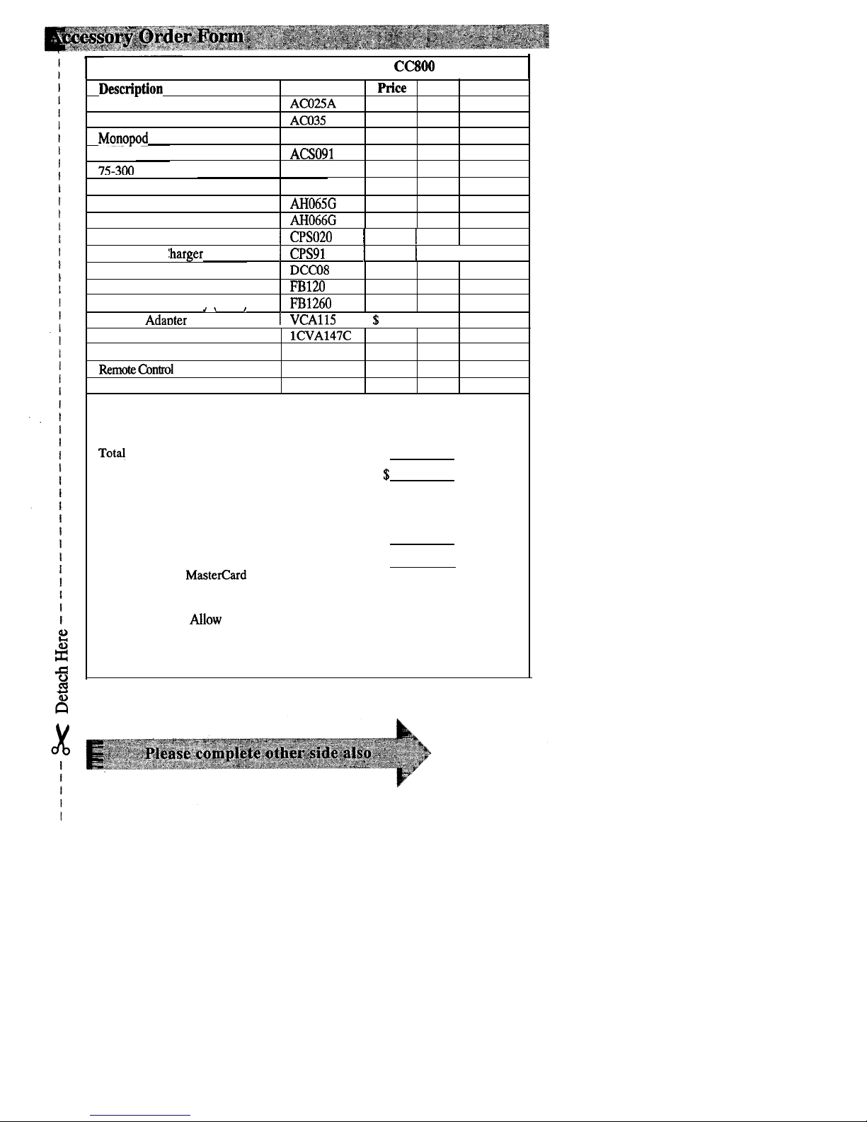
Order Form for Camcorder Model CC800
Description
Part No.
Soft Camcorder Case
ACO25A
Super Lightweight Tripod AC035
Monppod
AC036
Shoulder Stra
P
ACSO91
75-300 Cable Transformer
AH011
price
Qty. Total
$ 59.95
$ 69.95
$ 39.95
$ 13.95
$ 1.90
Y-Adapter
Coaxial RF Cable
Coaxial RF Cable
AH25
$ 1.95
AH065G
$ 6.99
AH066G
$ 8.99
AC Adapter/Charger
( CPSO20
1 $159.95 1
AC Batterv Clharger
1
CPS91
1 $ 59.95 1
I
Car Cord Adapter
Rechargeable Battery (2 Hr.)
Rechargeable Batterv (1 Hr.)
DCcQ8
$ 74.95
PB120
$ 59.95
I%1260
$ 49.95
.\
I
Cassette Adaoter
1
VCA115
I % 49.95 I
RF Output Adapter
75 Cable Transformer
RemotecontrOl
Audio/Video Output Cable
lCVA147C
$ 52.30
193983 $ 6.95
221125
$ 39.95
221205 $ 19.95
Prices are subject to change without notice.
To@ Merchandise ($10 Minimum
Order) . . . . . . . . . . . . . . . . . . . . . . $
Sales Tax
. . . . . , . . . . . . . . . . . . . . . . . . . . . . . . . . . . . . . . . . . . . . . . . . . . . . . . . . . . . . . . . . . . . . . . . . .
$
We are required by law to collect the appropriate
sales tax for each individual state, county, and
locality to which the merchandise is being sent.
Shipping, Handling, and Insurance . . . . . . . . . . . . . . . . . . . . . . . . . . . . . . . . . $
5.00
Total Amount
Enclosed . . . . . . . . . . . . . . . . . . . . . . . . . . . . . . . . . . . . . . . . . . . . . . . . $
Use VISA or
Master&d
preferably. Money order
or check must be in U.S. currency only. No COD
or cash.
l
Allow 8 weeks for delivery.
l
All accessories are subject to availability.
l
Where applicable, we will ship a superseding model.
Page 14

Charge your order on your VISA
or MasterCard by
filline in below
USE YOUR CREDIT CARD
IMPORTANT: Copy complete account number
from your VISA card
IMPORTANT: Copy complete
account
number
from your Mastercard
Copy Number
above
YOUI
name on
MasterCard
AUTHORIZED SIGNATURE
Prices are subject to change without notice.
L
print or type your name and
address clearly. ‘Ibis will be
mailing label.
your
A complete and correct order will
save you days of waiting.
r---------------------------
I
1 Name:
I
I
1 Street:
I
I
Apt:
I
I
I
City:
I
I
I
t
State:
Zip:
I
I
----______-----------------
A
Please make sure that both
sides of
this
form
have
been filled
out completely.
6
Page 15

To order accessories, contact your local Dealer.
If a dealer is not nearby, you can also follow the directions below to order by
telephone or direct-by-mail.
United States ahd Canada Orders
To place your order by phone, have your Visa or Mastercard ready and call
the toll-free number listed below between 8AM and 8PM Eastern Standard
Time.
Use this number only to place an order for accessory items listed on
this order form.
l-800-338-0376
Most times your order will be shipped UPS within 72 hours of receipt. If ever
it is not possible to ship within 30 days, we will notify you with an update on
your order and an option to cancel.
To place your order by mail, detach and mail the completed order form with
credit card information, money order, or check in U.S. currency (made payable
to Thomson Consumer Electronics, Inc.) to the following address:
Video Accessories
PO Box 8419
Ronks, PA 17573
For more information on these accessories (or current prices), write to the
following address:
Video Accessories Customer Service
Thomson Consumer Electronics, Inc.
Distributor & Special Products
2000 Clements Bridge Rd
Deptford, NJ 08096-2088
International Orders
This offer is valid only in the United States and Canada. For international
orders, please send your request for a price quotation (not an order) to:
International Customer Service
Thomson Consumer Electronics, Inc.
Distributor & Special Products
2000 Clements Bridge Rd
Deptford, NJ USA 08096-2088
Page 16

1. Unpack the camcorder and accessories.
l
Save the packing materials and box in case you ever need to ship or store your
camcorder.
l
The items shown below are packed with your camcorder.
If any are missing or
appear damaged, contact your dealer immediately.
Camcorder: Model CC800
AC Adapter/Charger
Part No.
CPSOZO
Rechargeable
6-Volt Battery
Part No. FB1260
Shoulder Strap
Part No. ACS091
Cassette Adapter
Part No. VCAllS
Cassette Adapter
Batteq
(Size “AA” 1.5 Volt)
Audio/Video Output Cable
Part No. 221205
Clock Cell
3-Volt Mien, Lithium Cell
Maxell No. CR2025 is
available from most
I-1
drug stores and camera
shops. Use of otber cells
present a risk of fire or
expktsion.
Page 17

2. Attach a power supply.
Adapter/Charger
Reference Marks
POWER
Indicator
Power Connector
1. Connect the power connector’s
connector flush against the back of the
small plug into the
DC
OUT jack
camcorder, and slide it in the direction
on the adapter/charger.
of the arrow as shown.
2. Align the reference mark on the
3. Plug the adapter/charger’s plug into an
power connector with the mark on
operating outlet. The adapter/
the camcorder. Hold the power
charger’s
POWER
indicator will light.
Charged Battery*
__~-
1. Match the reference mark on the
battery to the reference mark on the
camcorder.
2. Hold the battery flush against the
camcorder and slide it in the
direction of the arrow.
* The battery must be charged before it can be used the first time.
Details are on page 18.
(continued on next page)
9
Page 18

PUSH
Here to Close
\
Cassette Compartment Door
3.
Insert a tape.
5.Adjust
the handstrap to fit
*
i
l
Slide
EJECT.
your hand.
l
Turn the tape wheel on the cassette
to remove any slack from the tape.
l
Insert the cassette with the tape
wheel facing up and the tape window
facing out.
l
Press on the area labeled
PUSH
until
the cassette door locks into place.
4. Slide the
LENS COVER
control to open the lens cover.
l
Lift the flap on the hand strap and
separate the velcro strip.
l
Insert your hand, adjust the strap to
fit snugly, and refasten the strap.
10
Page 19

TC-2O/TC-30 Switc
‘Handstrap Velcro Strip
(Under Flap)
&Select a recording speed (SP
or EP) with the
W/H’
switch.
l
SP - Standard play provides the best
picture, but the shortest recording
time (20 minutes with a TC-20 tape).
l
EP - Extended play provides three
times the recording time as SP
(60 minutes with a TC-20 tape).
EP has slightly more picture noise in
normal playback.
7. Set the tape length
TC-2O/TC-30 switch.
This switch must be set for the
camcorder to correctly calculate the
recording time remaining on the tape
in the camcorder.
l
Select
TC-20
if you are using a tape
with 20 minutes or less recording
time when using SP recording speed.
l
Select
TC-30 if you are
using a tape
with more than 20 minutes recording
time when using SP recording speed.
(continued on next page)
11
Page 20
Electronic Viewfinder
Eyepiece Focus Control
POWER
(VCRlOFFlCAMERA
-
I
POWER Indicator
$
Switch
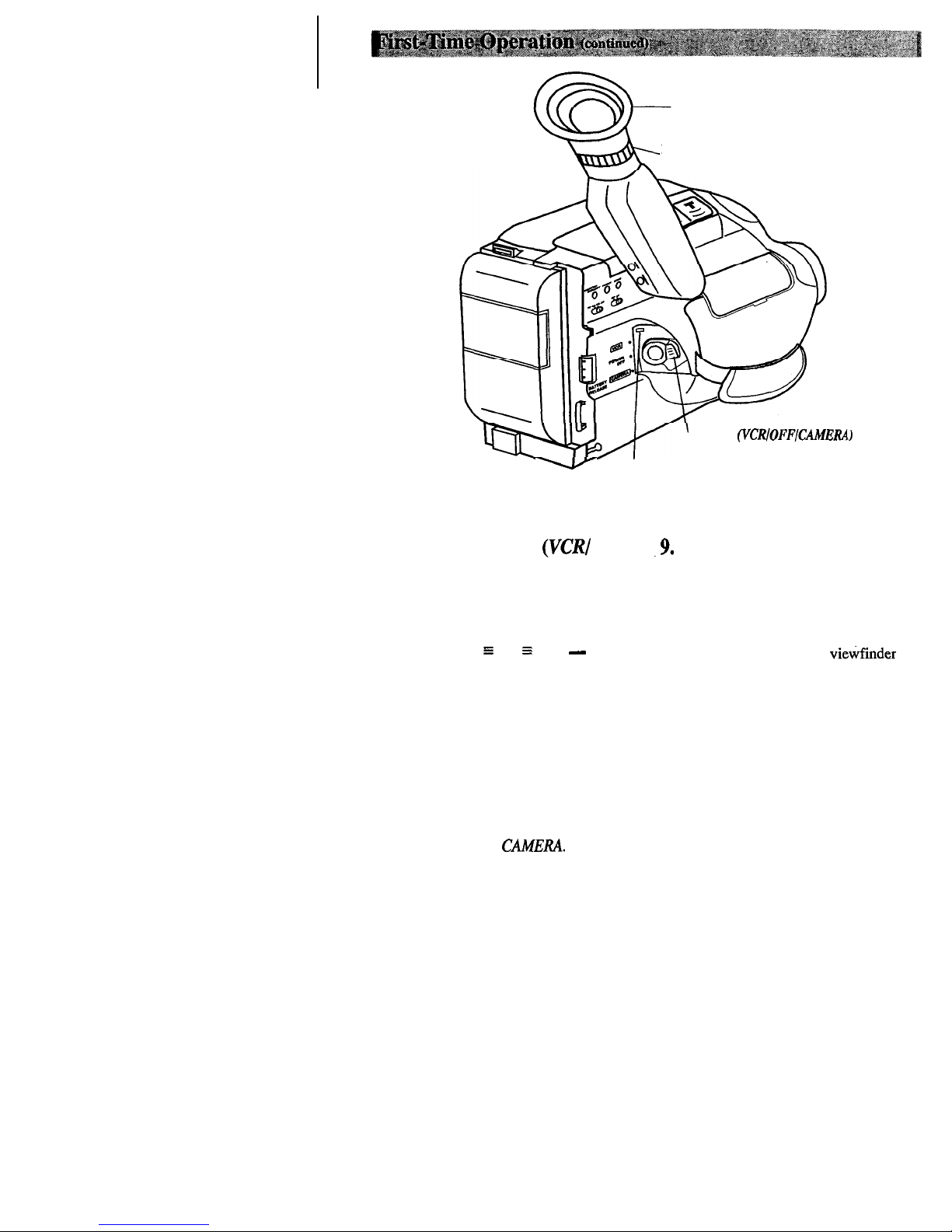
8. Place the POWER
(VW
.9. Adjust the viewfinder and
OFF/CAMERA) switch in
eyepiece focus control.
CAMERA.
l
Rotate the viewfinder into a
The
POWER
indicator will light and
comfortable operating position.
the camcorder
will
enter the record-
pause mode.
* Turn the eyepiece focus control to
z
PAUSE 3and - appear
in the viewfinder when the camcorder
adjust the focus of the
vietinder
for
your vision.
is in record pause.
The position of this switch tells the
camcorder whether you want to record
(CAMERA), turn the power off (OFF),
or play back tapes
(VCR).
The camcorder will automatically turn
off if it remains in record pause for
five minutes. Place POWER in OFF
and then back in
CAMERA.
12
Page 21
POWER
Indicator
WER (VCR/OFFlCAMERA)
Switch
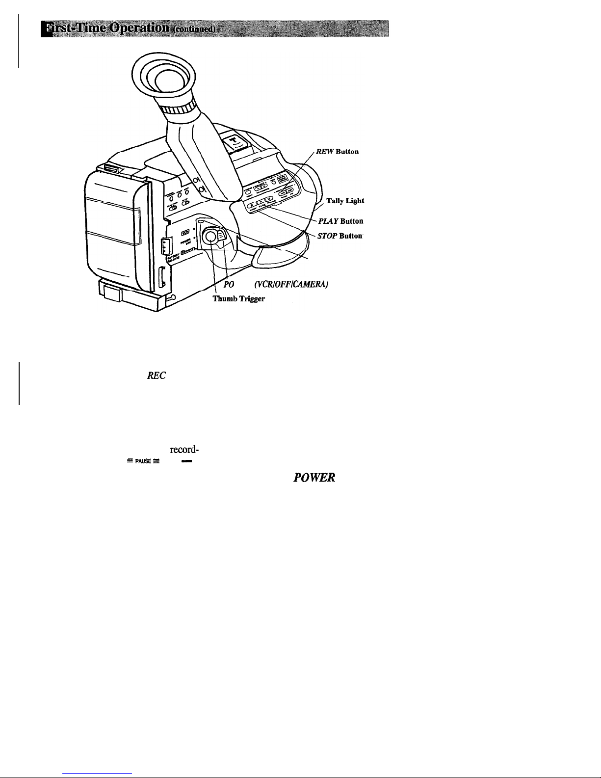
10. Start and stop recording.
l
Press and release the thumb trigger
to start recording. REC will
appear in the viewfinder, and the
tally light will light when the
camcorder is recording.
l
Press and release the thumb trigger
again to stop recording. The
camcorder is now in the record-
pause mode ( =
PAUSE =
and
-
appear in the viewfinder).
11. Play back what you have
recorded.
l
Place the
POWER
switch in
VCR.
l
Press
REW
to rewind the. tape.-
* Press
PLAY
to play back the tape
in the viewfinder.
l
Press
STOP
when you are finished
playing back the tape.
l
Details on viewfinder playback are
on page 44.
12.
Place the POWER switch in
OFF to turn off the
camcorder.
The
POWER
indicator will turn off.
(continued on next page)
13
Page 22

13. Review camcorder’s operating controls.
Power Zoom Buttons
*W” - Wide Angle
“T -
Telephoto
Electronic Viewfinder
Zoom
Adjust
\
Eyepiece Focus Control
Button
\
FOCUS LOCK
Button
Microphone
Lens,
\
DISPLAY
Button
0%.
I
Remote Control Sentir
14
Page 23

13. Review camcorder’s operating controls.
(continued)
DATEITIMEICHAR
SELECT + and - Buttons
(Also
TRACKING
Buttons)
Q.(Quick)
REVIEW Button
(Also EDIT
Button)
I
DATEITlhlElCkX4R
SET
Button
I
STOP
Button
PLAY
Button
.
-
EDIT SEARCH +
n II . 11 II
\
STOP/PLAY/PAUSE
REdi FF
I
FF
Button
(Also EDIT
&ARCH + Button)
SEARCH - Button)
POWER (VCRlOFFKAh4ERA)
Switch
’
Thumb Trigger
BATTERY RELEASE
Button
AUDIO, RF DC
OUT,
and
VIDEO
Shoulder Strap Attachment Ring
A&b
Battery or Power Connector for
AC Adapter/Charger Here
15
Page 24

I
1
Using the Adapter/Charger to Power Your Camcorder
The power connector attaches to the camcorder and lets you power your camcorder
directly from standard household power. The adapter/charger operates on 100-240
volts, 50/60 Hz, so it can be used virtually anywhere in the world to power the
camcorder or recharge the battery.
To AC
100~24OV,
Power Connector
BATTERY
RELEA
Attach Adapter/Charger
1. Connect power comrector’s small plug
into
DC
OUT jack on adapter/charger.
2. Hold the power connector flush against
the back of the camcorder, and slide it
to the right in the direction of the
arrow as shown.
3. Plug the adapter/charger’s plug into
the nearest AC outlet (lOO-24OV,
50/6OHz).
4. If the adapter/charger is properly
connected, its
POWER
indicator will
light.
Remove Adapter/Charger
1. Unplug the adapter/charger from the
wall outlet.
2. Press and hold
BATTERY RELEASE
on the camcorder while sliding the
power connector to the left and off.
Using an optional plug adapter
An optional plug adapter may be required
in some countries.
AC
100~240V
1. Plug the adapter/charger’s plug into
the AC plug adapter.
2. Plug the AC plug adapter into the
AC outlet.
16
Page 25

Using the Battery to Power Your Camcorder
The battery must be charged as described on the next
page
before it can be used the
first time. Initial charging will take approximately 70
minutes. When fully charged,
the battery should supply about 55 minutes of operating time (depending on how much
you use zoom and pause). Conserve battery power by turning the camcorder off during
recording breaks.
Note: The small marker switch on top of the battery is for use as a personal reminder to help
you remember to recharge the battery.
It has no other function.
BATTERYRELEA
(VCRfOFFlCAMER.4)
Switch and Indicator
Attach the Charged Battery
If the power connector is attached to the
3. Place the
POWER
switch in
CAMERA.
camcorder, remove it before attaching the
The
POWER
indicator will light.
battery. Also, install the lithium clock
cell before attaching the battery pack.
Remove the Battery
Details on page 28.
Press and hold
BATTERYRELEASE
on
1. Align the reference mark on the battery
the camcorder while sliding the battery to
with mark on back of camcorder.
the left and off.
2. Hold battery flush against camcorder
and slide it in direction of arrow.
ATTENTION: THE PRODUCT THAT YOU HAVE PURCHASED
USES A RECHARGEABLE BATTERY. AT THE END OF ITS
USEFUL LIFE, UNDER VARIOUS STATE AND LOCAL LAWS, IT
@
MAY BE ILLEGAL TO DISPOSE OF THIS BATTERY INTO THE
I
w
MUNICIPAL
WASTE STREAM. CHECK WITH YOUR LOCAL
Ni-Cd
SOLID WASTE OFFICIALS FOR DETAILS IN YOUR AREA FOR
RECYCLING OPTIONS OR PROPER DISPOSAL.
17
Page 26

Using the Battery to Power Your Camcorder
(continued)
To AC Wall Outlet 100440
Adapter/Charger
-
Side-B
Ch’ARGE
Indicator
END Indicator’
Battery Release Switch
POWER
Indicator
CH-iRGE
Indicator
aptedcharger - Side A
END
Indicator’
Battery Release Switch
A
hIFRESH
Switch
and Indicator
Charging Batteries
If the power connector is attached to the
DC
OUT jack on the adapter/charger,
remove its plug.
1. Plug adapter/charger into nearest AC
outlet
(Ml-24OV, 50/6OHz).
The
POWER indicator lights.
2.
3.
I
I
I
Align reference mark on battery with
mark on adapter/charger and press
battery pack-in until it locks.
If the battery is properly connected, the
CHARGE
indicator on that side of the
adapter/charger will flash.
Notes: You
may charge two batteries at
the same time. Whichever battery
you
attach first will charge first. The CHARGE
3. When discharging is completed, the
indicator will light for the battery that
is
REFRESH
indicator will turn off, and
waiting to be charged.
the
CHARGE
indicator will flash while
If you try to charge a battery that has not
the battery charges.
been charged for a long period of
time, it
may take a few minutes for the
CHARGE
indicator to flash.
Use
REFRESH
on Side
A
The battery will provide increased
operation time if you “refresh)) it after
five charges. The
REFRESH
feature
“refreshes’? the battery by completely
discharging it.
1. Attach battery to side A of the
adapter/charger.
2. Press REFRESH. The REFRESH
indicator will light and the battery will
begin discharging.
Note:
The battery you .attach to side A will
always be refreshed first. Then the battery
attached to side B will be charged before
the battery in side
A.
4. After the battery is charged, the
END
indicator will light.
_ _ .._
4. After one battery is charged, its
END
5. Press the battery release
switch
whrle
indicator will light. The other battery’s
removing the battery from the
CHARGE
indicator will flash while it
adapter/charger.
is being charged.
(continued on next page)
18
Page 27

Using the Battery to Power Your Camcorder
(COII~~IWI)
Battery Warning
The battery warning will appear and flash
in the camcorder’s viewfinder when the
battery needs to be recharged.
4
l-----l
l
When this indicator appears, place the
POWER
switch in
OFF
to turn off the
camcorder before replacing the battery.
l
After replacing the battery, place the
POWER
switch in
CAMERA
to place
the camcorder in record pause.
The battery warning will not be recorded
on the tape when it appears in the
viewfinder.
Battery Warning
in Viewfinder
Battery Care and Storage
II~~
l
Recharging takes approximately 70
minutes depending on the battery’s
condition.
l
Refreshing takes approximately 210
minutes depending on the battery’s
condition.
l
After repeated charging and use,
operation time will gradually decrease.
When operation time becomes too short
to be useful, it is time to replace the
battery.
l
If the battery discharging must be
stopped in the middle, remove the
battery from the adapter/charger before
unplugging it from the AC outlet.
l
Let a hot battery cool down before
attaching it to the adapter/charger.
l
The battery will also provide better
service if its power is completely.
drained before storing it for long
periods of time (30 days or more).
l
The battery should be charged in the
temperature range of 50-95°F
(10-3X)
to prevent damage.
. Do not. operate the battery at
temperatures below 32°F (OC) or above
104°F (40C). The battery may be
damaged if operated at temperatures
above 122°F (50C). Operation time
will decrease at extremely low
temperatures.
l
Store the battery at normal room
temperature.
19
Page 28

Optional Car Cord Adapter
The optional DCCOS car cord shown on
page 2 allows you to power your
camcorder from the cigarette lighter
socket of a car, truck, or RV. It converts
1Zvolts to a 6-volt output.
Note:
Consult the installation and operating
instructions enclosed with the DCC08 for
complete operating instructions.
/
Using the DCCOS Car Cord Adapter
~-----------~~~.-_l.~
Cigarette
POWER
Indicator
Optional DCCOS Car Cord Adapter
1. Place the
POWER
switch in
OFF
to
turn off the camcorder.
POWER
indicator turns off.
2. If the battery is attached to the
camcorder, remove it.
3. Hold the power connector flush against
the back of the camcorder and slide it
to the right in the direction of the
arrow as shown.
4. Take the vehicle’s cigarette lighter out
of the socket.
5. Insert the car cord’s cigarette lighter
plug into the vehicle’s cigarette lighter
socket. The
POWER
indicator on the
car cord adapter will light.
6. Place the
POWER
switch in
CAMERA
to turn on the camcorder. The
POWER
indicator lights.
20
Page 29

l
In case of fire or theft, make a video
recording of your home and contents to
store in a safe place.
l
Try to make sure indoor scenes are
well-lit. This
imtroves
picture quality
and color reproduction.
l
Do not move the camcorder rapidly
from side-to-side while recording.
A steady, gradual “pan” avoids
blurring and “jitter”.
l
Use the viewfinder to make sure the
camcorder is level while recording or
your scenes will appear “tilted”.
l
Do not bump or tap the camcorder’s
microphone while recording because
this sound will be recorded.
l
Fading in and out of scenes will make
your videos appear more professional.
l
Be aware of video and audio
backgrounds. Background details
barely noticed while you are taping
may show up as visual “clutter” on
your recording. Background noises
(especially TV sets, radios, household
.appliances, traffic sounds, etc.) can
detract from the sound you want to
record.
l
Avoid long “still” shots of landmarks
and scenic attractions. Recordings are
more interesting if they include people
and details. “Local color” will give
travel videos lasting appeal. Consider
recording a familiar or landmark scene
from an unfamiliar vantage point.
l
Include close-up shots of individuals
when taping family outings or group
functions.
Traveling Tips
l
Write down your camcorder’s serial
number and keep it separate from the
camcorder when traveling. If your
camcorder is lost or stolen, you will be
able to identify it.
l
Make sure you have any plug adapters
that you may need before taking your
camcorder to other countries. Consult
your dealer for advice.
l
Carry your camcorder in a carrying
l
Use extra care to avoid damage to your
case when traveling.
Seepage 4
for a
camcorder and accessories when
case designed especially for this
operating them at a beach or pool.
camcorder. An ordinary suitcase or
Spray, sand, and dust should be
carry bag does not offer the protection
avoided. If
yourlens
has been exposed
your camcorder needs. Treat your
to the elements, clean it only with
camcorder as carry-on luggage to
proper lens cleaning supplies.
protect it from rough handling.
21
Page 30

We recommend that our cassettes be used with your camcorder. Use of poor quality
tapes or tapes that have been damaged or mishandled can contaminate the video heads,
resulting in a snowy picture or no picture at all during playback. Because there is no
control over the type of tape purchased or rented by consumers, head cleaning is not
covered under warranty. It is considered normal maintenance.
The automatic head-cleaning system minimizes the need for accessory cleaners or
cleaning by a Servicenter. This system is activated whenever you insert or remove a
cassette.
Erase Protection - Safety Tab
You can use your video cassettes over and over again. To erase a previous recording,
just record over it.
A. Remove
safety tab.
B. Cover hole
with vinyl tape.
Recording Speeds and Times
The camcorder records and plays back in standard speed (SP) or extended play (EP).
Select the recording speed with the
SP/EP
switch. The selected speed will be displayed
in the viewfinder.
Listed below are the maximum SP and EP recording times for popular VHS-C cassettes.
33
YY
l
SP - Standard play provides the
best picture (less picture noise),
but the shortest recording time
Recording Time
(20 minutes with a TC-20 tape).
Cassette SP
EP
l
EP - Extended play provides three
TC-20 20 Min. 60 Min.
times the recording time as SP
TC-30
30 Min.
90 Min.
(60 minutes with a TC-20 tape).
TC-40*
40 Min.
120
Min.
EP has slightly more picture noise
than SP in normal playback. This
* Will probably be available soon.
may not be noticeable.
Page 31

Inserting and Removing Cassettes
to Close Cassette
Before inserting a cassette, turn the tape
wheel on the side of the cassette in the
direction shown to remove any slack in
the tape.
ape Wheel
+
1. Attach a power supply. Then slide and
release
EJECT
to open the cassette
compartment.
2.
Insert or remove the cassette.
3. Close the cassette compartment door
by pressing on the area labeled
PUSH
until it locks into place.
Cassette
Car&
and Storage
_~
l
When you are $nished with a cassette,
rewind it, remove it from the
camcorder, and label it.
l
Store cassettes vertically in their
protective cases at normal room
temperatures. Do not leave your
camcorder or cassettes in a car or
outdoors for an extended period.
Excessive heat or cold may damage
your cassettes.
l
Keep the cassette away from strong
magnetic fields such as electric motors
and other devices.
-~~
l
Keep dust from entering the cassette
compartment. All dust is abrasive and
will cause excessive wear on the tape
and the camcorder’s recording or
playback heads.
l
Do not use cassettes with damaged or
spliced tape.
l
Do not use a cassette if it has been
damaged or exposed to moisture. The
tape may jam and/or damage your
camcorder.
23
Page 32

POWER
Switch in
/
Camera Edit
/
Camera edit allows you to position the
tape when the camcorder is in record
4
pause. Place
POWER
in
CAMERA.
I
l
Press and hold
REWIEDIT SEARCH
-
to visually search recorded tape
in reverse.
8
Press and hold
FFIEDIT SEARCH +
to
visually search forward on the
recorded tape.
Release button to return to record pause
at that point on the tape. Press the thumb
trigger to start recording at this point.
Quick Review
Press Q.(quick)
REVIEW
when the
camcorder is in record pause to review
the last few seconds of a recording. The
POWER
switch must be in
CAMERA.
/
The camcorder will play back the last
I
I
few seconds of the recording, return the
tape to its previous position, and return to
record pause.
Lilly Light
The tally light lights when the camcorder
is recording.
Microphone
The microphone picks up the sound
during a recording. It is more sensitive to
sounds coming from the direction the
lens is pointed.
24
\
Tally Light
Flying Erase Head
A separate erase head is mounted on
the spinning headwheel (hence the term
“flying”). This allows you to make clean
edits without the “glitches” or “rainbow
noise” that may occur at the beginning
and end of recordings.
Auto Head Cleaner
The camcorder has an automatic head-
cleaning system. Whenever a cassette is
inserted or removed, this system is
activated.
The head-cleaning system minimizes the
need for accessory cleaners or cleaning
by a Servicenter.
Electronic Indexing
Each time you begin recording after the
date in the camcorder advances and you
insert a cassette, an index mark is
automatically recorded.
When you play the tape in a VCR with a
compatible “VHS Index Search System”,
the VCR will locate the marks
automatically. See
VCR owner’s manual
for detaiki.
INDEX
appears briefly in the viewfinder
when an index mark is recorded.
Page 33

The camcordet’s electronic viewfinder is a miniature monitor that displays the picture
seen by the camcorder when recording.
Electronic Viewfinder
Eyepiece Focus Control
m
The eyepiece focus control lets you set
the focus of the viewfinder for your
personal visio . If you wear eyeglasses,
you probably
k
without them.
n operate the camcorder
It is easiest to set the correct focus by
focusing on one of the vieWfinder’s
on-screen displays (such as the time
counter). Look through the viewfinder
and adjust the eyepiece focus control for
your vision.
The eyepiece focus control does not affect
the focus of the picture actually recorded
by the camcorder.
Tilt
Adjustbent
For convenient viewing, you can rotate the viewfinder about 180”.
25
Page 34

1 Focus
0
Indicators
i
/
I
90MI N--@ TapeTime
2 Dew
0
Warning
;s,
KARL IS
1
Focus
0
POWER
switch must be in
l
Manual Focus Indicators ( rlA
CAMERA.
)
appear when focus is adjusted
manually.
l
Manual Focus Lock Indicators
()
l 4)
appear when manual focus
is locked
l
Low-Contrast Indicators (
-Ii-i- )
flash when the auto-focus system
cannot focus properly.
l
Details are on pages 34-35.
@
Dew Warning ( b
/
j
,
I
J
/:
/:
The dew indicator appears when
excessive moisture (condensation)
has entered the camcorder. The
camcorder will not operate when
this indicator appears. Place the
camcorder in a warm, dry area until
this indicator disappears. When the
)
dew indicator disappears, the
camcorder will operate.
3 Tape Time-Remaining Display
0
l
The approximate time remaining
on the tape in the camcorder is
automatically displayed in the
1
l
The time-remaining indicator will
start flashing when the remaining
tape time reaches two minutes
@
Low Battery ( 4 )
l
This indicator appears when it is
time to recharge the battery.
l
Details are on page 19.
5
Lithium Cell ( Zb )
0
l
This indicator appears when the
clock cell has not been installed or
it needs to be replaced.
l
Details are on page 28.
6
Title
0
l
The title you create appears in this
area of the viewfinder.
l
Details are on page 32.
@
Status, Cassette Warning ( @Q
and
TAPE END
l
The ZUX indicator appears here
when the camcorder is recording.
l The
=
PAUSE =and - indicators
appear during record pause.
l
The @ indicator flashes when
the
POWER
Remaining
Warning
Indicator
),
switCh is set to
viewfinder.
(continued on next page)
26
Page 35

Cassette Warning,
and TAPE END
I
0
8 INDEX--INDEX
0
=PAUSE=
9 FADE--
FADE
Memory Stop
DEC
25 1994
0
10 hite
--
MWB
Balance
DEC 25.94
AM
IO:35
CAMERA
and the safety tab has
been removed from the cassette.
l
The l&J indicator also flashes
when the
POWER
switch is set to
CAMERA
and there is no cassette
in the camcorder.
l
TAPE END
appears when the end
of the tape is reached during
recording or a cassette is inserted
with its tape already at the end.
0
8
INDEX
l
INDEX
appears briefly when the
camcorder is automatically making
an index mark during recording.
l
Details are on page 24.
0
9
FADE
l
FADE
appears when you press
FADE
and hashes when the
camcorder is fading in or out.
l
The POWER
switch must be set to
CAMERA.
l
Details are on page 36.
0
10
White
Balance
l
The indicator for the manual white
balance selected with the
A4W.B
(manual white’ balance) button
appears here.
l
No indicator appears for automatic
white balance.
l
The POWER
switch must be in
CAMERA.
l
Details are on page 37.
0
11 Tape Speed
(SP or EP)
l
The tape speed selected with the
SPIEP
switch appears here.
l
Details are on page 22.
@
Elapsed Time-Counter with
Memory Stop
l
The time counter appears during
recording and playback. It is not
recorded on the tape.
l
An
“M” appears in front of the time
counter when memory stop is on.
l
Details are on page 38.
0
13 Date and Time Indicators
l
These indicators are recorded
whenever they appear.
Details are
on pages 30-31.
27
Page 36

Install the Clock Lithium Cell
The clock cell indicator & will appear in the viewfinder when the cell has not been
installed or needs to be replaced. The cell should last approximately one year.
(+ Side Facing Out)
1. Make sure camcorder is turned off, and
remove any power supply attached to
the camcorder.
4. Close the compartment cover. It will
click into place.
2. Press release tab of clock cell compart-
To remove battery
i
ment cover and open the compartment.
To remove battery, insert a pointed non-
3. Insert the clock cell with the “+”
metallic object between battery and
I
terminal facing out.
compartment and lift.
I
28
Page 37

After the date and time have been set, they can be displayed and recorded on your
tapes. The clock cell must be installed.
DATEITIiUElCHAR
SELECT +
and
-
DATE/TIME1
r-7
Switch and Indicator
Set the Date and Time
7.
1. Install the clock cell.
2. Attach a power supply.
3. Place the
The POWER indicator will light.
4.
Press
date and time display appear with a
flashing
I
flashing cursor lets you know which
part of the display you are setting.
5. Repeatedly press
SELECT
appears.
Note:
advance the digits.
6.
Press
move flashing cursor to the next part
of the display.
Note: Press
advance the
POWER
DATEIT~MElCIdAR SET. The
cursor
+ or +- until the correct month
.Press and hold the button to rapidly
DATEITIMEJCH-iR SET
and hold the button to rapidly
switch in
on the month. The
DATEITIMEICHAR
fla$hiig
cursor.
CAMERA.
to
Repeat steps 5 and 6 until you have
entered the correct month, day, year,
hour (including AM or
minutes.
Note: The clock begins when the minute
digits stop flashing. The clock does not
keep time while any digits are flashing.
PM),
and
Tb Correct the Displays
Press
DATEITIMEICIUR SET
the time and date and select the item you
want to change. Repeatedly press
DATEITIMEKHAR SELECT +
enter the correct digit(s).
Repeatedly press
SET
to remove
start the clock.
DATEITIME CHAR
the
flashing cursor and
(continued on next page)
to display
or - to
29
Page 38

,
Y
Button
Select the Date, Time, or Title You Want to Record on Your Tape
The clock cell must be installed and the
date and time set before they can be
selected and recorded.
1. Attach a power supply and place
POWER switch in
CAMERA.
The
POWER indicator will light.
2. Press
DISPLAY
to select one of the
displays.
l
Date Display:
The date will be
displayed and recorded.
l
Auto Date:
The date will be
automatically recorded for
approximately five seconds.
l
Auto Date Titler Display:
The date
is automatically recorded across the
center approximately four times
larger than the normal displays.
30
l
Time Display:
The time will be
displayed and recorded.
l
TV On-Screen Display: The
viewfinder displays will appear on
the screen of a TV connected to the
camcorder during record pause.
l
Date Off:
No date or time will be
displayed or recorded.
l
Titler Display:
The title you created
will be displayed and recorded.
Note: If no title has been created,
SET
CHAR appears and a title can be created.
Details are on page
32.
Page 39

To Record the Date, Time, or Title Display on Your Tape
1. Place the camcorder in the record-
* This display mode has just been
pause mode.
selected with
DISPLAY.
2. Press
DISPLAY
to display the mode
l
The tape has been changed or the
you want to record in the viewfinder.
tane comuartment opened.
The mode you select will be recorded
whenever it appears in the viewfinder.
If you select either auto mode
(AUTO
DATE
or auto date titler), it will
automatically appear, be recorded for
five seconds, and then disappear
whenever:
l
The date has been set or changed.
3. Press
DISPLAY
to remove the display
from the viewfinder when you are
finished recording it.
4. To record the display again, place the
camcorder in record pause and press
DZSPLA Y.
31
Page 40

You can create a title (up to ten characters), store it, and record it.
DATEITIMEICHAR
SELECT + and
-
DATE/TIME1
CIL4R
SET
Button
POWER Switch and Indicator
DISPLAY Button
Creating and Recording a Title
1. Place
POWER
switch in
CAMERA.
POWER
indicator will light.
2.Repeatedly press
DISPLAY
to display
SET
CHAR menu.
3.Press
DATE/TIME/CHAR SET. The
CHARACTER SET MODE
menu
appears with a flashing cursor.
CHARACTER SET MODE
;<:o
A B C D E F G
HIJKLHNO
PQRSTUVW
XYZiiiiiiii’
01234567
89:.-l!?
4. Repeatedly press
DATEITIMEICHAR
SELECT
+ or - until the first character
for your title is flashing.
Note: Press and hold the button to rapidly
advance the flashing cursor.
5.Press
DATEITIiUElClX4R SET
to
select the character.
6. Repeat 4 and 5 until you have selected
up to ten characters for a title.
7.Press
DATEITMEICIUR SET
to
display the title and remove the
CHARACTER SET MODE
menu.
Note: Only one title can be stored. To
create a new title, store it over the old one.
l--l
KARL IS 1
8.To record the title at any time,
repeatedly press
DISPLAY
to
superimpose the title over the scene in
the viewfinder.
9.Press the thumb trigger to start
recording. The title will be
superimposed and recorded over the
scene you are recording.
lO.When you are finished recording the
title,
press
DISPLAY
to remove it from
the viewfinder.
32
Page 41

The motorized zoom lens allows you to zoom in and out at two speeds for close-ups or
wide-angle shots just by pressing one of the power zoom buttons.
Zoom
AdJust
Button
\
Power Zoom Buttons
T
= Telephoto
= Wide Angle
h
Adjusting the Zoom Buttons
The zoom buttons are easily controlled by
your index and middle fingers when you
hold the camcorder through the handstrap.
The power zoom buttons on the
camcorder can be rotated to three
positions.
l
Slide the zoom adjust button while
rotating the buttons in a different
position
l
Release the button to lock the buttons in
that position.
Power Zooming
To zoom in or out slowly, press the zoom
button lightly. To zoom in or out quickly,
press the zoom button firmly.
l
Press T to move the lens in- the telephoto
(close-up) direction.
l
Press W to move the lens in the wide-
angle direction.
Note: If you zoom in on low-contrast subjects
while recording and auto focus cannot work
properly,
the camcorder will zoom out and the
low-contrast (
+--
) indicator will appear in
the viewfinder.
33
Page 42

I
Power Zoom Buttons
“W” a&“p
LOCUS
LOCK
Button
in
CAMERA
Auto Focus
The camcorder will focus automatically.
No indicators appear in the viewfinder
during auto focus.
Notes:
the viewfinder indicates the autofocus system may not operate correctly due to
low illumination, low or no contrast, repeated
patterns, or two subjects at different distances
overlapping. Focus the camcorder manually.
If the camcorder has been zoomed in on the
subject and the auto-focus system cannot
achieve proper focus, the camcorder will
automatically zoom out. This may allow the
focys system to focus properly. If proper
focus still cannot be achieved, adjust the focus
manually.
I
j ’
The low-contrast indicator
(-%*i
-) in
Macro Focus
The auto-focus system may be used for
recording subjects very close to the
camcorder. Increased illumination may
produce better results.
1. Press power zoom button
the lens is completely zoomed out.
2. Position the subject or scene in the
center of the viewfinder.
“Up’
until
34
Page 43

Manual
Focus
Indicators
(A
r-r-
Manual
Manual Focus
Displays in Viewfinder
’
JAW
Contrast
Indicators (
,
I
A-WA. )
1
Under certain conditions, such as those
listed, you may need to focus manually.
1. Press power zoom button
“T”
to zoom
in on your subject. To maintain
proper focus throughout the zoom
range, you must zoom in on the
subject before adjusting the focus.
2
Press and hold
pressing power zoom button
“W”
to display a clear picture in the
FOCUS LOCK
while
“T”
or
center of the viewfinder focus.
The A A indicators appear in the
viewfinder. The 4 or b indicator will
flash. When the focus cannot be
adjusted any farther, the A indicator
will flash. When the focus cannot be
adjusted any closer, the A indicator
will flash.
3. Release the power zoom button to lock
in the manual focus. The
b.4
indicators appear in the viewfinder.
4. To turn off manual focus, press
FOCUS LOCK. The
F 0 4
indicators
disappear from the viewfinder.
Some conditions that may require the use
of manual focusing during recording are:
l
When recording a subject through a
window.
l
When recording a subject having a close
foreground and a background that is far
away..
l
When recording two subjects at different
distances that overlap in the same scene.
l
When the subject is not in the center of
the electronic viewfinder.
l
When recording in low-light situations.
l
When recording a scene with fast
motions, like a tennis swing.
35
Page 44

You can add a professional touch to your recordings when you fade in and out of
scenes. The picture will gradually appear or disappear. The speed of the fade is
automatically controlled by the camcorder.
FADE
Button’
Fade In
1. Place the
POWER
switch to
CAMERA.
The
POWER
indicator will light. The
camcorder will enter record pause.
Center the subject or scene that you
want to record in the viewfinder.
2. Press
FADE. FADE
will appear in the
viewfinder.
3. Press thumb trigger to start recording.
The screen turns blank and the
camcorder will automatically fade into
the scene you have selected.
FADE
flashes in the viewfinder while
the camcorder is fading in.
FADE Indicator: Fade feature
turned
on.
FADE
Indicator Flashing: Fading in
pWXSS*
I
FADE
Display in Viewfinder
Fade Out
1. During recording, press
FADE.
FADE
will appear in the viewfinder.
2. Press the thumb trigger to stop
recording. The camcorder will
automatically fade out of the scene
and enter record pause.
FADE
flashes
in the viewfinder while the camcorder
is fading out.
36
Page 45

Making colors look natural is what white balance is all about. This
is
achieved by
adjusting the way the camcorder “sees” and records the light source in the scene you
wish to record. Your camcorder is equipped with automatic white balance. However,
under certain conditions, such as recording an object with various shades of the same
r
color or when recording a predominant red or brown object outdoors, you may want to
adjust white balance manually.
PressMWB
(Manual
White
I)
Balance) to
Display in
Viewfinder
II
4uto White Balance Outdoors- Cloudy
km
Button
To Adjust White Balance
1. Place the
POWER
switch in
CAMERA.
The
POWER
indicator will light.
2. Press MWB (manual white balance)
until one of the manual white balance
indicators appear in the viewfinder.
l
Select -% when recording outdoors
on a cloudy day.
l
Select :+ when recording outdoors
on a sunny day.
l Select
1%:
when recording using
halogen or tungsten lighting.
l
Select MWB when shooting subjects
with different color temperatures
and adjust the white balance as
follows:
Outdoors - Sunny
c
Manual White Balance Halogen or Tungsten
Light
-
Note:
Connecting your camcorder to a
color TV monitor may be helpful when
making white balance adjustments.
A. Point camcorder at a white, flat
object such as a piece of white
paper.
B. Press and hold MWB for at least
three seconds.
The MWB indicator will flash
while the camcorder is adjusting
white balance and stop flashing
when it is ready to record.
3. To have camcorder automatically
control white balance, repeatedly
press
A4WB
until no white balance
indicator appears in viewfinder.
37
Page 46

E
I’
!
I
I1
The time-counter display shows the actual time elapsed when recording a program or
playing back a segment of a prerecorded tape.
Note the time counter reading when you finish recording or playing back a tape. For
example, you recorded for 10 minutes. Later,
recording - insert the tape, display the time counter, and fast forward the tape until the
time counter reads “0:
1O:OO”.
RESET Button
It helps you locate the end of programs.
you
want to locate the end of your
I
1
I’
!
COUNTER MEMORY Butt
REW Button
I
POWER Switch
To Use the Memory-Stop Feature
The memory-stop feature helps locate a
certain point on the tape. When memory
stop is on, the tape will stop
automatically during rewind or fast
forward when the time counter reaches
M
O:OO:OO.
1. Press COUNTER MEMORY to turn
the time counter’s memory-stop
feature on or off. When memory stop
is on, an M appears before the time
counter in the viewfinder.
M
0:OO:OO
Time Counter
Display.with
Memory Stop
Turned
On
Viewfinder Display
2. Locate the place on the tape you want
to return to, and press
the time counter to M
RESET
to set
0:OO:OO.
3. Continue to record or play the tape.
When you want to return to the place
you marked, press the thumb trigger to
stop recording, or the
stop playing back the tape.
4. Place the POWER switch in VCR.
Press REW. The tape will rewind to
the time counter reading of M
Notes: Whenever the time counter is
displayed, you can reset it to iU
pressing
Whenever memory stop is on, the camcorder
will stop rewinding or fast forwarding when
the counter reaches h4
rewinding or fast forwarding, press the
or
The time counter does not operate during
high-speed rewind or fast-forward operation.
The time counter’s memory is automatically
cancelled when the power supply is
disconnected.
RESET.
FF
button again.
STOP
0:OO:OO.
button to
0:OO:OO.
0:OO:OO
by
To continue
REW
38
Page 47

-_^
The approximate time remaining on the tape in the camcorder is automatically
displayed in the viewfinder. The
TC-2O/TC-30
switch must be set to the correct
position before the camcorder can correctly calculate time remaining.
Tape Time
P0~~~swit~b
Set the
TC-2OlTC30
Switch
Before recording, set the
TC-2O/TC-30
switch for the size of tape you are using.
l
Select
TC-20
when using a tape with
20-minutes or less recording
t@e
when using SP recording speed.
l
Select
TC-30
when using a tape with
more than 20-minutes recording time
using SP recording speed.
Note: The
time-remaining display does not
work for TC-40 tapes.
Remainin
Indicators
TAPE END
90MIN
-9OMIN
I
Viewfinder
vi!
1
:
89:IN
i
I
I
SPYIN
1
2MIN
(Flashing)
1
IHIN
(Flashing)
1
OMIN
(Flashing)
The time-remaining indicator will start
flashing when the remaining tape time
reaches two minutes.
TAPE END
appears when the tape
reaches its end during recording or a
cassette is loaded whose tape is already
at its end.
39
Page 48

The camcorder uses a smaller size cassette, but records in standard
--
VI-IS
format. The
cassette adapter allows you to play your VI-IS-C cassettes in a VCR just like other
standard VHS cassettes.
Insert the VHS-C cassette into the cassette adapter. Insert the cassette adapter into the
VI-IS
VCR like a normal
VI-IS
cassette.
Install Cassette Adapter’s Battery
Battery
1. Remove battery compartment cover.
2. Install supplied “AA” battery so
positive (+)
align properly with
and
negative (-) ends
(+)
and (-)
terminals in battery compartment.
3. Replace battery compartment cover.
Insert Cassette into Cassette Adapter
Tape Wheel
1
1. Before inserting the cassette into the
adapter, remove any slack in the tape
by turning the tape wheel on the side
of the cassette.
2. Slide EJECT to the right to open the
cassette compartment lid.
Notes: Replace the battery when the load
time becomes much longer than normal.
Remove the battery from the cassette adapter
if it will not be used for a month or more.
This will prevent possible damage from
battery leakage. If leakage occurs, wipe up
the liquid inside the compartment and-replace
the battery with a new one.
--.--____P
A
Cassette
I n
,/-
IUECT
Switch
3. Insert the cassette
window on the left and facing up.
Allow the cassette to drop into the
adapter. Do
with
the tape
not force the cassette.
(continued on next page)
40
Page 49

Insert Cassette into Cassette Adapter
Load Detector
(COII~~~W-I)
4. Gently close the cassette compartment
lid until it locks into place. Make sure
the cassette reel area under the adapter
is free to turn while the cassette is
loading.
Note:
You should hear a whirring sound
while the tape loads. The adapter’s load
detector will automatically retract into the
adapter.
Remove Cassette from Cassette Adapter
1. Slide the adapter’s EJECT switch to
the right. The load detector will
extend from the side and the whirring
sound indicates the tape is being
released before the adapter’s cassette
~
2. Use the access hole on the bottom of
the adapter to push the cassette up and
remove it from the adapter.
3. Gently close the adapter’s cassette
compartment lid.
compartment lid-opens.
41
Page 50

..-.“.
“__xc_
The camcorder’s shoulder strap is designed to let you carry the camcorder from your
shoulder and - when you are ready to shoot -bring the camcorder to shooting position
in one quick movement.
To Attach the Shoulder Strap
1. If the strap keeper is over a double
section of the strap, slide the strap
keeper off the end of the strap.
Replace the keeper on the strap
between the buckle and the end of the
strap as shown.
2. Loop the end of the strap over the top
of the shoulder strap attachment ring.
Then thread the end of the strap back
through the keeper and buckle. Make
sure the strap is not twisted.
3. Attach the other end of the strap to the
other shoulder strap attachment ring.
4. Adjust the shoulder strap to the desired
length. Then slide both keepers up
snugly against the shoulder strap
attachment rings to prevent the strap
from slipping.
The lens ring can be removed so you can attach optional accessories, such as wide-
angle lens, lens extender, or lens filter kit.
To remove the lens ring, grasp the lens
ring and turn it counterclockwise.
Turn the accessory lens clockwise into the
camcorder’s lens. Make sure the lens is
tightened firmly, but do not over tighten.
42
Page 51

General Camera Section
Power requirement: 6VDC Image Sensor:
l/3’
CCD Imager
Power consumption: 6.5 watts (normal) Tripod Mount: One
l/4”
x 20 threaded
Weight: 1.6 lbs. (720g) hole
Dimensions - Including Viewfinder Lens: fU1.8
4.5” x 4.6” x 7.2”
12:1(5.5-66mm)
(115 x 118 x 182mm)
Diameter: 43 mm
Video Recorder Section
Format: VHS-C
Record/Playback System:
Four video record/playback heads
One flying erase head
Video Signal: EIA Standard NTSC
color
This equipment has been tested and
found to comply with the limits for a
Class B digital device, pursuant to Part
15 of the FCC Rules. These limits are
designed to provide reasonable protection
against harmful interference in a
residential installation. This equipment
generates, uses, and can radiate radio
frequency energy and, if not installed and
used in accordance with the instructions,
may cause harmful interference to radio
communications. However, there is no
guarantee that interference will not occur
in a particular installation. If this
equipment does cause harmful
interference to radio or television
reception, which can be determined by
turning the equipment off and on, the
user is encouraged to try to correct the
interference by one or more of the
following measures:
l
Reorient or relocate the receiving
antenna.
l
Increase the separation between the
equipment and receiver.
l
Connect the equipment into an outlet on
a circuit different from that to which
the receiver is connected.
l
Consult the dealer or an experienced
radio/TV technician for help.
Alterations or modifications carried out
without appropriate authorization may
invalidate the user’s FCC right to operate
the equipment.
Page 52

EJECT
Button
FF
Button
POWER Indicator
POWER Switch in VCR
Viewfinder Playback
Viewfinder playback is the simplest way
to watch tapes using the camcorder.
To Play Back a Tape
1. Place POWER switch in VCR. The
POWER indicator will light.
2. Slide EJECT and insert the cassette
you want to play back. Close the
cassette compartment.
3. Press PLAY to begin playback. If
necessary, adjust tracking.
During playback, use the playback
features on the
n&page.
4. Press STOP when you are finished.
44
(continued on next page)
Page 53

‘Pape
Positioning
Place POWER switch in VCR and press
STOP.
l Press and quickly release REW or FF
to rewind or fast-forward the tape.
Press
STOP
to stop the tape.
l
Press and hold
R@W
or
FF
more than
two seconds for high-speed rewind or
fast forward.
Note: The time counter does not operate
during high-speed rewind or fast forward.
Visual Searching
l During playback, press and release FF
or
REW
if you want to search the tape
visually in forward or reverse.
l Press
PLAY
to return to normal
playback.
l For brief searching, press and hold FF
or REW for more than two seconds.
l Release the button to return to normal
playback.
Stop-Action Pause
l
During playback, press
PA USE
to “stop
the action” and view one frame of the
tape.
l Press PLAY to return to normal
playback.
Tracking
During playback, streaks may appear in
the playback picture. Press either
TRACKING
button to move the streaks
up or down and out of the picture.
l
During stop-action playback, pressing
one TRACKING button may reduce
picture “jitter” (picture bouncing up
and down). Some “jitter” is normal
during stop-action viewing.
Simultaneously press both
TRACKlNG
buttons to return tracking to its preset
center.
Note: The
TRACKING
buttons may have no
effect on tapes recorded on other camcorders
or VCR’s.
45
Page 54

“_ ..,.....,.. ,
__ ^
To connect your camcorder
to a TV monitor (or VCR) with
AUDIO/VIDEO
IN jacks,
you will need the audio/video cable that came packed with your camcorder.
If your TV is already connected to a VCR,
YOU
can attach the camcorder to the VCR
and watch what the camcorder is recording or playing on the TV.
Back of
Mono VCR or
TV Monitor
0
1 White
Audio Plug
Audio/Video
Output Cable
c-c
2 Yellow Video Plug
V
-OR-
Back of
Stereo VCR or
Y-Adapter
0
I
White
TV Monitor
(Optional)
Audio Audio/Video
0..
Jack
Installation
@
Attach the white plug on one end of
the audio/video output cable to the
AUDIO IN jack on the TV (or VCR).
Note:
If your TV (or VCR) has stereo
jacks, attach the white audio
plug to the one labeled MONO. If one is
not labeled
MONO, you
may need a
Y-adapter, such as AH25, shown on
page 3 to hear both channels.
I
46
@
Attach the yellow plug to the VIDEO
IN
jack on the TV (or VCR).
0
3 Attach the white plug on the other end
of the audio/video output cable to the
white AUDIO plug (located under the
small cover) on the back of the
camcorder.
@Attach the yellow plug to the yellow
VlDEO
plug on the camcorder.
(continued on next page)
Page 55

- ,._..... ,^,
,
Playback
Opetition
and How to Copy
apes
on the VCR
1. A. Camcorder connected directly to
TV: Turn on the TV and tune it to
the video input channel.
B. Camcorder connected to VCR that
is already connected to TV: Turn
on VCR and place it in the “line” or
“camera mode”. (If your VCR does
not have a “line” or “camera
mode”, consult the VCR owner’s
manual.)
OPerate
the TV as you
normally
do!
to see the signal
coming from the VCR.
2. Place the
PO$ER
switch in VCR to
turn on the camcorder. The POWER
indicator will light.
3. Press PLAY.
l
If noise bars appear on the screen,
press
TRACKfhG
-or +.
l
During playback, use the playback
features on page 45.
4. To copy what the camcorder is playing,
5.
Press STOP when you are finished.
place a blank cassette in the VCR, and
press the VCR’s RECORD button.
Note: Press
EDIT
to start camcorder
playback when copying tapes to improve
picture reproduction. Make sure the
memory-stop feature is turned off (press
COUNTER MEMORY)
or the camcorder
will enter play pause when the counter
reaches M
0:OO:OO.
Viewing What fhe Camcorder is Seeing (or Recording)
$awMsw~~*~w~
*-av,**b:,sxwa
,,.:.I.,: .__ ::i ~-1: : .‘:I ::j.- .-‘..,.” ::,:
1. A. Camcorder connected directly to
TV: Turn on the TV, and tune it to
2.
the video inPut channel.
B. Camcorder connected to VCR that
is already connected to TV: Turn
on VCR and place it in the “line” or
“camera mode”. (If your VCR does
3’
not have a “line” or “camera
mode”, consult the VCR owner’s
manual.) Operate the TV as you
normally do to see the signal
coming from the VCR.
Place the POWER switch
in CAMERA.
Note: When the camcorder is used as a
camera, turn the TV’s volume down to
prevent a high-pitched squeal caused by
feedback.
Press the thumb trigger to begin
recording. You can watch what the
camcorder is seeing (or recording) on
the TV screen.
Note: During record pause, you can see the camcorder’s displays on the TV screen. Repeatedly
press
DISPLAY. Details are on pages 30-31.
47
Page 56

“j
“,..
.,...
. . . . .
,.,,,, _L1.^./
To connect your camcorder to a TV without audio/video inputs, you will need an
optional
lCVA147C
RF output adapter and an optional coaxial RF cable, such as
AH065G
or
AH066G
shown on page 3.
If your TV has AUDIO and VIDEO IN jacks
(or is connected to a VCR), refer to pages 46-47.
VHF
Ante1
h
0
z
Optional
Transformer
(Such as 193983)
Optional Coaxial
RF Cable
(such as
AH065G
or
AHO66G)
Back of TV
IiVFROMAhT
Connector
1
CH3/CH4 Switch
Optiokal
RF Output Adapter
(lCVA147C)
Installation
0
1
Disconnect the VHF antenna from
your TV. Connect the antenna to the
iN
FROM
ANT connector on the RF
output adapter if you are going to leave
the adapter connected to the TV.
Note: If your VI-W antenna is the flat
twin-lead type attached by two screws,
you
will
also need an optional 3OOff5 ohm
transformer,
such
as
193983 shown on
page 3.
48
OUT,
VIDEO Jacks
0
2
Attach one end of the optional coaxial
RF cable to the OUT TO TV connector
on the adapter, and attach the other end
to the VHF input on your TV as
shown.
Note:
If your TV has 300 ohm screw
terminals, you will need a 75/300 ohm
transformer, such as AH01 1,
shown on
page 3.
0
3 Attach the RF output adapter’s plug to
the AUDIO, RF DC OUT, and VIDEO
jacks located under the small cover on
the back of the camcorder.
Page 57

Playback Operation
1. Set the
CH3KH4
switch on the RF
output adapter to channel 3 or 4.
2. Turn on the TV, and tune it to the
same channel you selected with the
RF output adapter’s
CH3lCH4
switch.
3. Place adapter’s VCRITV switch in
VCR.
4. Place POWER in CAMERA. POWER
indicator will light.
5. Press PLAY on the camcorder.
l During playback, use the playback
features
described on page 45.
l
If noise bars appear on the screen,
adjust tracking
as described on
page 45.
6. Press STOP on the camcorder when
you are finished.
Viewing What the Camcorder Is Recording
,,,,,;LAE
_
l.,~;~:.~~~~,::-..:.:;l:.,~“~~.~.~~~.~~.
,;~.:=;.,;,;:
~*&4va;wr
x*:p&ty<&,*?
vr
vlbr *‘l.i~~~P~*l,~~~~~~~~~~~:~~~
1. Turn on the TV and tune it to channel
3. Place adapter’s VCRITV switch in
3 or 4. When the camcorder is used as
VCR.
a camera, turn the TV’s volume down
4. Place POWER in CAMERA. POWER
to prevent a high-pitched squeal
caused by feedback.
indicator will light.
2. Set the
CH3fCH4
switch on the RF
5. Press the thumb trigger to begin
output adapter to the same channel
recording. You can watch what the
you selected on the TV.
.
camcorder is seeing (or recording) on
the TV screen.
Note: During record pause, you can see the camcorder’s displays on the TV screen. Repeatedly
press
DISPLAY. Details are on pages 30-31.
Normal TV
Viewing EZZEEZE~~~~-,--,-,~~-.~,~
-w*a<-
* I &~“~*~“*.~~~>Y&:
For normal TV viewing, you may leave
the camcorder and place the adapter’s
the RF output adapter hooked up to the
VCRITV switch in
TV.
TV. Disconnect the adapter’s plug from
Note to Cable TV Installer
This reminder is provided to call your attention to Article 820-40 of the
National Electrical Code (Section 54 of Canadian Electrical Code, Part I),
that provides guidelines for proper grounding and, in particular, specifies
that the cable ground shall be connected to the grounding system of the
building as close to the point of cable entry as practical.
--
49
Page 58

Cleaning the Camcorder
To clean the camcorder’s exterior, remove any power source connected to the
camcorder and gently wipe it with a clean soft cloth.
Cleaning the Camcorder's
tins
~:w~~~~~~~~~~:" .'~;:;,,,:l;,,
:.l.:-' s...!
:
,,,,,, i,;.;,;;.:.
'%
.,,. :x.'.'.
y
RA-,.l, .,k&x*r I *,x: P,b?:wm***,,4 4+,4"- we, _I '*, I,
I
To clean the camcorder’s lens, blow it with a blower brush, and then gently wipe the
lens with cleaning tissue and commercially prepared cleaning solution designed for use
on camera lens. Improper cleaning may scratch the lens.
Cleaning the Camcorder’s Viewfinder
The viewfinder eyepiece can be removed for cleaning.
1. Turn the eyepiece
counterclockwise and pull it out.
2. Remove dust using a blower brush.
3. Reattach the eyepiece by aligning
the reference marks, and then turn
the eyepiece clockwise.
Page 59

Proper Care and Storage
l
Keep dust and grit from entering the
camcorder’s cassette door. Dust and
grit are abrasive, and will cause
excessive wear to both the camcorder’s
recording/playback heads and cassettes.
l
Always replace the lens cap on the lens
when the camcorder is not in use.
l
Before handling your camcorder, make
sure your hands and face are free from
any chemical products such as suntan
lotion, as it may damage the finish.
l
Do not attempt to disassemble your
camcorder. There are no user-
serviceable parts inside.
l
Avoid operating your camcorder
immediately after moving it from a cold
location to a warm location. Give the
camcorder
1-M
to 2 hours to reach a
stable temperature before inserting a
cassette. When the camcorder is
moved from cold to warm,
condensation may cause the tape to
stick to the headwheel and damage the
headwheel or tape.
l
Do not aim your camcorder at the sun
or other bright objects.
l
Do not leave your camcorder in direct
sunlight for extended periods of time.
The resulting heat buildup could
permanently damage the camcorder’s
internal parts.
l
Do not operate the camcorder in
extremely humid environments.
l
The camcorder can be damaged by
improper storage or handling. Do not
subject the camcorder to swinging,
shaking, or dropping.
l
Do not store the camcorder in
temperatures below -22°F (-30C) or
above 149°F
(6X).
l
When the camcorder is not in use,
always remove the cassette and
AC adapter/charger or battery.
l
Retain the original carton for future
storage or shipping purposes.
l
Do not operate the camcorder near the
ocean as salt water or salt water spray
may damage the internal parts of the
camcorder.
l
Do not operate the camcorder for
extended periods in temperatures below
40°F (4C) or above 95°F (35C).
l
Do not expose the camcorder or
adapter/charger to rain or moisture. If
either component becomes wet, turn off
the power and take the unit to an
Authorized RCA Camcorder
Servicenter.
l
Do not use an adapter/charger or
batteries other than the ones specified
for the camcorder. Use of the wrong
accessories may cause damage to the
camcorder.
51
Page 60

Troubles sometimes are caused by simple “faults” that
YOU
can easily correct without
the help of a service technician by first checking a few basic remedies.
Before you call or take your camcorder to an Authorized RCA Camcorder Servicenter,
look below for the type of trouble you are experiencing. Then perform the simple
checks and adjustments listed for that trouble.
If service should be necessary, the warranty information lists what your warranty
covers and explains how to get service.
No power
Won’t record or
playback
Won’t playback
Won’t record
No picture
Camcorder turns
itself off
Tape stops during
rewind or fast
forward
52
l
Place the
POWER
switch in
CAMERA
or
VCR
to turn on
the camcorder. The
POWER
indicator will light.
l
If using battery, it may need to be recharged.
If using AC adapter/charger, make sure it is plugged into a
working outlet.
l
If the dew indicator ( 4) flashes in the viewfinder, there is
moisture in the camcorder. Wait until the dew indicator no
longer appears before operating the camcorder.
l
Make sure
POWER
switch in correct position for operation.
l
There may not be a cassette in the camcorder.
l
Try ejecting and reinserting the cassette.
l
The cassette tape may be broken, try another cassette.
l
You may have reached the end of the cassette, try
rewinding it.
l
POWER
switch must be in
VCR
position.
l
Safety tab has been removed. (See
page 22.)
l
POWER
switch must be in
CAMERA.
l Open LENS COVER. See page 10.
l
Place
POWER
switch to
OFF
and then in
CAMERA
or
VCR
to turn camcorder back on. If camcorder is left in record
pause or play pause for several minutes, it will turn itself
off to prevent tape wear.
Time-counter memory may be on. Whenever an
“M’
appears with the time-counter display, the camcorder will
stop rewinding (or fast forwarding) when counter reads
M
0:OO:OO.
Press
REW
or
FF
again to continue rewinding or
fast forwarding, or press
COUNTER MEMORY
to turn off
the memory-stop feature.
Page 61

Camcorder remains
in pause mode
Sound is too low or
distorted
I
Dew indicator
flashing in
viewfinder
Poor auto-focus
operation
Viewfinder displays
are out of focus
Colors do not look
natural on recording
Title recorded on
tape
Date and/or time
were recorded on
tape
l Press PLAY to return to normal playback.
l Subject was too far from camcorder.
l If the dew indicator (
4
) flashes in the viewfinder, there
is moisture in the camcorder. Wait until this indicator no
longer appears before operating the camcorder.
l Subject is dark or behind glass. Auto-focus may not
work under these conditions. See pages 34-35.
l Subject is not in center of viewfinder or two subjects are
at different distances. Focus manually. See pages 34-35.
l
Lens is smudged, and image appears unfocused.
l Eyepiece focus control is misadjusted.
l The small BRZGHT and
CONTRAST
controls on the
bottom of the viewfinder control brightness and contrast
of the viewfinder. These controls are set at the factory
and should require no adjustment. If the brightness or
contrast of the viewfinder ever does require adjustment,
carefully remove the small plastic cover and use a plastic
screwdriver. Make the adjustments with caution to
prevent damaging the miniature controls. Replace the
plastic cover.
l Try adjusting white balance. Seepage 37.
l Title is recorded whenever it appears in viewfinder.
Press DISPLAY to remove it from viewfinder.
See page 32.
l Displays will be recorded on tape whenever they appear
in the viewfinder. Press DISPLAY to remove them from
viewfinder when recording. See pages 30-31.
l When AUTO DATE or auto date titler mode is selected,
display will automatically be recorded when you begin
recording or change the cassette. Seepages 30-31.
(continued on next page)
53
Page 62

Date and/or time are
l Clock lithium cell battery may need replacing. See page 28.
I
incorrect
l Date or time may need to be set. Seepages 28-29.
Vertical white lines
l This may occur when background extremely contrasts with
appear when
shoot-
the subject.
ing bright object
Error number
l
Try disconnecting power source. Wait ten seconds and then
(EOI,
E02, etc.)
connect power source again. If error number does not
appears in
disappear from viewfinder, consult your Authorized RCA
viewfinder
Camcorder Servicenter.
Page 63

What your warranty covers:
l Any defect in material or workmanship.
l 90 days for labor charges.
l One year for parts.
The warranty period for rental units
begins with the first rental.
What we will do:
l Pay any Authorized RCA Camcorder
Servicenter the labor charges to repair
your camcorder.
l Pay any Authorized RCA Camcorder
Servicenter for the new or, at our
option, refurbished replacement parts
required to repair your camcorder.
How you get service:
l Check with your RCA Dealer or call
l-800-336-1900 for the Authorized
RCA Camcorder Servicenter nearest
you.
If an Authorized RCA Camcorder
Servicenter is conveniently near you:
l Take your camcorder to the Authorized
RCA Camcorder Servicenter of your
choice.
l Show the Servicenter Representative
your.sales
receipt or other evidence of
purchase date.
l Pick up your camcorder when repairs
are completed.
If an Authorized RCA Camcorder
Servicenter is not located conveniently
near you:
l Pack the camcorder so that it will not
be damaged during shipping. (We
recommend using the original carton
and packing materials.) Include any
cables and other accessories originally
furnished with the camcorder.
l Include in the camcorder carton
(1) a copy of your sales receipt or other
evidence of purchase date, (2) your
name and address, and (3) a brief
description of the problem.
l Ship the camcorder to an Authorized
RCA Camcorder Servicenter.
l
Pay any charges billed to you by the
Servicenter for service not covered by
the warranty.
What your warranty
does not
cover:
l Customer instruction. (Your owner’s
manual clearly describes how to install,
adjust, and operate your camcorder.
Any additional information should be
obtained from your Dealer.)
l
Installation and related adjustments.
l
Cleaning of video/audio heads.
l Damage from misuse or neglect.
l Batteries for clock or other features.
l A camcorder that has been modified or
incorporated into other products or is
used for institutional or other
commercial purposes.
. A camcorder purchased or serviced
outside the USA.
How state law relates to this warranty:
l This warranty gives you specific legal
rights, and you also may have other
rights that vary from state to state.
Product registration:
l Please complete and mail the product
registration card
packed with your
camcorder. It will make it easier to
contact you should it ever be necessary.
The return of the card is not required
for warranty coverage.
If you purchased your camcorder
outside the United States:
l See your dealer for details.
Page 64

A
--
AC Adapter/Charger, Safety
Instructions
...
.......................................
.lU
Accessories, Included
........................... 8
Accessories,
Optional.. ...................... l-7
Accessory,
Order
Form ....................
.5-7
Adapter/Charger,
Using..
................
.9,16
Attaching the Shoulder Strap..
...........
.42
AUDIO/RF DC
OUTJVIDEO
Jacks
........................................
15,46,48
Audio/Video Cable
....................
.8,46,48
Auto Focus
.......................................... 34
Auto Head
Cleaner
............................
.24
B
Y-
BATIERYRELEASE Button.....15,16,17
Battery
Level
Warning
.................
.19,26
Battery Marker Switch
........................ 17
Battery Safety Precautions
...........
.17-19
Battery, Care
and
Storage..
................
.19
Battery, Charging................................
18
Battery, Using
Rechargeable......9,17-19
BRIGHT Control..
.........................
.15,53
c
--
Camcorder
Lens,
Cleaning ................
.50
Camcorder, Cleaning
.......................... 50
Camcorder, Powering..
.................
.16-20
Camcorder, Turning On..
...................
.12
Camcorder,
Unpacking..
......................
.8
Camera Edit ........................................
24
CAMERA/OFF/VCR Switch
...........................
lo-11,12-13,15,19,27,
.......................
29-30,32,38,44-45,47,49
Car
Cord Adapter,
Optional..
..........
.2,19
Care
and
Maintenance..
................
.50-51
56
Care and
Storage
of Battery..
.............
.19
Cassette Adapter
...........................
.40-41
Cassette Adapter, Install Battery
.......
.40
Cassette
Care
and Storage
.................
.23
Cassette Door
............................
10,14,23
Cassette Indicators
..............................
26
Cassette, Inserting
..............................
.lO
Cassettes, Inserting and
Removing
.....................................
lo,23
CHARJDATEJTIME
SELECT + and - Buttons..
......
.15,29,32
CHARJDATEITIME
SET Button .............................
.15,29,32
Charging
the
Battery..........................
.18
Checking Problems.......................
.52-54
Cleaning Camcorder..
........................
.50
Cleaning
Lens
....................................
.50
Cleaning Viewfinder.. ........................
.50
Clock
Battery
Indicator.................
.26,28
Clock Cell, Installing..
.......................
.28
Contents
...............................................
.l
CONTRAST Control......................
.15,53
Controls
........................................
.14-15
Copying
Tapes..
............................ .46-47
COUNTER MEMORY Button.......
.15,38
D
-
-
Date and
Time Display.. ..........
.27,28-31
DATE/TIME/CHAR
SELECT +
and-Buttons..
......
.15,29,32
DATEITIMEICIUR
SET
Button
.............................
.15,29,32
DC Car Cord, Optional..
.................
.3,20
Design
Specifications
........................
.43
Dew Warning ......................................
26
DISPLAY Button..
...............
.15,30,31,32
Displays,
Viewfinder.. ..................
.26-27
Page 65

--
E
EDIT Button..
EDIT SEARCH t
EDIT SEARCH
EJECT Button..
Electronic Indexing..
Electronic Viewfinder..
EP
Indicator..
EPISP
Erase Protection..
Eyepiece Focus Control..
FADE
FADE
FadingInand Out..
FF
(Fast Forward) Button. ..15,24,44-4 5
First-Time Operation..
Flying Erase Head..
FOCUS LOCK Buttons..
Focus Display
Focusing
Hand Strap, Adjusting
Handstrap..
Important Safeguards
Included Accessories
INDEX
Indexing, Electronic..
InsertingaCassette..
Inserting and Removing
Cassettes..
................................
Button..
-
Button..
..............
................................
Switch..
Button
Indicator..
Indicator
....................
...............................
--
F
................................
...........................
...........................
.......................................
-
H
.....................................
--
............................
............. ........................
............
.............
.10,12,15,23,44
..........................
.................
.11,15,22,27
.........
.12,15,25
............................
....................
............................
...............
26,34-35
B
.......................
I
.....................
........................... .8
.........................
..........................
.15,47
.15,24
.15,24
.24
.15,25
.22,27
.22
.14,36
.27,36
.36
.8-15
.24
.14,35
.34-35
.lO
lo,15
iv-vii
24,27
.24
.10
lo,23
--
L
LENS COVER
Lens..
..............................................
Lens, Cleaning
Lens Ring, Removing
Limited Warranty..
Low Battery Warning
Control..
...................................
.................
........................
.............................
...................
-A&
Macro Focus
Maintenance and Care..
Manual Focus
Memory Stop
Microphone..
Monopod, Using
MWB (Manual White Balance)
Button..
......................................
................
.....................................
................................
.................................
.................................. .2
........................................
-o-
OFFIVCRIC’ERA
...........................
......................
Operation, First-Time..
Optional Accessories..
Order Form, Accessory
PAUSE
Pause, Stop-Action
PLAY Button..
Playback
Button..
.......................................
Switch
lo-11,12-13,15,19,27,
.29-30,32,38,44-45,47,49
...................
.......................
....................
--
P
1
.......................
............................
...........
.13,15,44-45,47,49
.15,44-45
lo,14
lo,14
.50
.42
.55
.19,26
.34
.50-51
.35
.27,38
.14,24
.15,37
.8-15
l-7
.5-7
.45
.44-49
57
Page 66

Playback
Features
..............................
.45
Playback on a TV With
AUDIO/VIDEO IN Jacks
............
.46-47
Playback on a TV Without
Audio/Video
Inputs
....................
.48-49
Playback
Speeds
................................
.22
Playback, First
...................................
.13
Playback, Viewfinder
........................
.44
Plug Adapter..
....................................
.16
POWER
(CAMERAIOFFIVCR)Switch
...........................
lo-11,12-13,15,19,27,
.......................
29-30,32,38,44-45,47,49
POWER Indicator...........
lo-11,12-13,15
.............
19,27,29-30,32,38,44-45,47,49
Power
Connector
............................
.9,16
Power Zooming
.................................
.33
Powering
the
Camcorder..
............
.16-20
Problem Solving..
.........................
.52-54
Product Registration
................................
Inside Front Cover
Proper Care
and
Storage
....................
.51
-
-
Q
Q.(Quick)
REVIEW
Button . . . . . . . . . . . .
15,24
R
-
-
’
REC (Record) Indicator..
.........
.13,26-27
Recording and Traveling Tips
...........
.21
Recording
Speed...
.............................
.22
Recording, First
.................................
.13
Refreshing
the Battery
.......................
.18
Registration Card......Insid e Front Cover
Remote Control
Sensor..
....................
.14
Removing
the
Lens
Ring
...................
.42
RESET Button..
.............................
.15,38
REW (Rewind)
Button....13,15,38,44-4
5
RF Output Adapter, Optional..
.
..3,48-4
9
58
S
--
Safeguards,
Important.. .................. iv-vii
Safety Instructions, AC Adapter/
Charger
..............................................
iii
Safety Precautions
...
.............................
.1-H
Safety
Tab..........................................
.22
Searching,
Visual.. .............................
.45
Setting the Time and
Date
.................
.29
Shoulder Strap Attachment Rings
.15,42
Shoulder Strap,
Attaching..
................
.42
Solving
Problems
.........................
.52-54
SP Indicator ...................................
22,27
SPjEP
Switch..
....................
.11,15,22,27
Specifications
...................................... 43
Speed, Recording and Playback
........
.22
Status Indicators
........................... .26-27
STOP
Button..
.......
13,15,38,44-45,47,49
Stop-Action Pause
..............................
45
T
--
T
(ZoomButton).
.....................
.15,33,35
Table of Contents
..................................
1
Tally Light ................................
13,14,24
TAPE END Display..
...............
.26-27,39
TAPE END
Indicators
..................
.26-27
Tape Copying
............................... .46-47
Tape Time Remaining .......................
.39
Tape Time-Remaining Display..
........
.26
TC-2O/TC-30
Switch..
..............
.11,15,39
Things to Avoid
..................................
51
Thumb Trigger
..........................
13,15,36
Tilt, Viewfinder
..................................
25
Time
and Date
Display.. ..........
.27,28-31
Time Counter
.................................
27,38
Page 67

TIMEkXARIDATE
SELECT +
and- Buttons..
......
.15,29,32
Z
-7
TIhfElChW?/DATE
Zoom Buttons
.....................
.15,33,34,35
SET Button
......
..i .....................
............................................
33
Time Remaining
b
15,29,32 Zooming..
rsplay
.............
..26,3 9
Title in Viewfinder
........................
26,32
Titler
..................................................
.32
TRACKING
Buttons
................
.15,44-45
Traveling and Recording Tips
...........
.21
Tripod, Using
........................................
4
Trouble Checks..
...........................
.52-54
Turning On the Camcorder..
..............
.12
u
-
-
Unpacking the Camcorder
................... .8
User Information
.................................
43
Using
Cassette Adapter
................
.40-41
--
V
VCRICAMERAIOFF
Switch
...........................
lo-11,12-13,15,19,27,
.......................
29-30,32,38,44-45,47,49
Video/Audio
Cable
....................
.8,46,48
Video Cassettes
.............................
22-23
Viewfinder
....................................
.12,25
Viewfinder Displays..
...................
.26-27
Viewfinder Playback
.........................
.44
Viewfinder, Cleaning
...........................
50
Visual Searching
.......................F .........
45
W (Zoom Button).
....................
.15,33,34
Warranty, Limited..
............................
.55
White Balance
.....................................
37
White Balance Indicator
...............
.27,37
59
Page 68

For your nearest home
entertainment Dealer
or Authorized Servicenter
call toll-free in the U.S.A.
1-800-336-1900
Canadian Consumers
-
Your toll-free numbers are:
English: l-800-522-0338
French: l-800-522-0445
If your camcorder needs service, please
contact your dealer or the nearest Servicenter
from the yellow pages. Please do not send
any products to the Indianapolis address listed
in this manual or on the carton. This will only
add delays in service for your product.
Thomson Consumer Electronics
600 N Sherman Dr, PO Box 1976
Indianapolis, IN 46206
%994
Thomson Consumer Electronics, Inc.
Trademark(s)@ Registered
Mama(s) RegIstrada(s)
Printed in Japan
Part Number
94-CCSOO-1
YU30103.306%
(VP)
 Loading...