

Page 1
www.SteamPoweredRadio.Com
I
I
I
I
I
I
I
ANTENNA
TUNING
UNIT
I
I
I
I
I
I
I
I
Type
BPA-10
I
I
INSTALLATION-OP~RATION-MAINTENANCE
I
I
I .
Printed
in
U.
S.
A.
I
I
INSTRUCTIONS
1B-30168-3-21-46
Page 2
www.SteamPoweredRadio.Com
I
Title
Technical Summary
Electrical Characteristics
Tube Complement . .
Mechanical Specifications
Description
Installation
Tuning
......................................•.....................••...................
Purpose
Construction .....
Circuit
Mounting
R-F
Connecfions
Remote Metering and
Static Drain
Tower Lighting,
............
General Considerations ........
Tuning Procedure with
Tuning Procedure without
Final Check
Remote Metering Equipment
.........
.... , ....................•.......••....
.........................•.....••...............................................
...................................................................•..........
.........•...........................................................
..........•....•..................•...........................................
.. ~ .....................................................................
..
......................••....••.••...........................................
TABLE
.... , ...........................................................
....
...................
..
.................
...................................
.............
Audio
.......
R-F
Bridge
R-F
....•....
Monitoring
.......
Bridge ...................
...........•.••................................................
.................................
...........•..•
.............•..
...
......
OF
......
. •
.........
CONTENTS
........
....
........
.
...............••
.•.....
..... .............•........••..........
..........
....
.
.......................................
..
..................
. . .
...........
............
.. ..........
·.·
...........................
..••.•
........
............
......
...
.............
......
................
...........•....
·•· . .
...
....
. .
.........
.......
.....
...
.....
.........
.........
...
,
..
. : . . .
.
.
. ·
.
.
.
.
Page
5
5
5
5
5
5
5
5
5
5
5
6
I
3
3
3
3
I
I
I
I
I
I
I
I
5
7
8
8
I
I
Maintenance
Parts
List
.........
Figure
1-Type
2-Simplified
3-Coupling
4-Antenna
5-Antenna
6-Antenna
2
BPA-10 Antenna Tuning Unit (Exterior View)
................•........••••...•.
..........................•..•.•...........•.........
Circuit Diagram (K-861732)
Circuit and Tuning Unit
Tuning Unit (Interior View)
Tunin·g Unit (S;hematic M-428316)
Tuning Unit (Outline M-428610)
........... , ...............................•..........
Network
.............•.....
, ,
.......
..
ILLUSTRATIONS
(K-861757)
......
.........•............
.........................................
.........
..
...
.......
.............
............................
.....
. · .
...........................
,
•...................
...
..................
............ ..
....•.....•.
8
I
9
I
4
6
.
7
9
10
.
11
I
I
I
I
I
I
I
I
Page 3
www.SteamPoweredRadio.Com
I
I
I
I
I
I
I
I
I
I
I
I
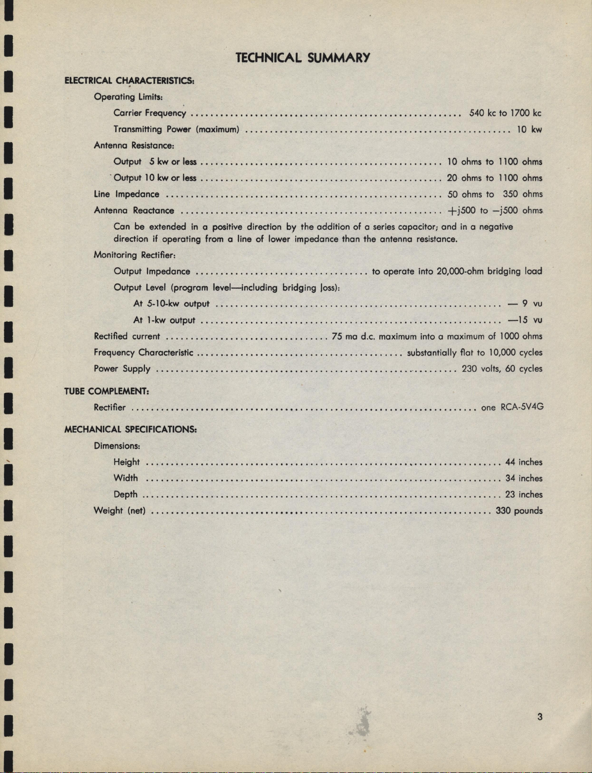
TECHNICAL
ELECTRICAL
TUBE
CHARACTERISTICS:
Operating Limits:
Carrier Frequency • • . • • • • • . • • • • • • • • • • • • • • . • . • . . . . . . • • . • . • • . . • . • . . . • • . . . • •
Transmitting
Antenna Resistance:
Output
· Output 10 kw
Line Impedance
Antenna Reactance
Can be extended in a positive direction
direction
Monitoring Rectifier:
Output Impedance
Output
At
At
Rectified current
Frequency Characteristic
Power Supply . • • . . • • .• . • • • • • . • • • • • • • • • . • • • • • . . . . . . . . . . . . . • . • . . . • . .. . • . . . • . . . 230 volts, 60 cycles
COMPLEMENT:
Rectifier . . . . . . . . • • • • • • • • • • • • • • • . • • • • • • • • • • • • . . . . . . . . . . . • • . • . . • • • • . . • • . • . • . . • . . one RCA-5V 4G
Power
(maximum)
5 kw
or
less
. • . • . . • • • . • • . . . • • . • • . . . . . . . . . . . . . • . . . . . . . . . . . • . . . l O
or
less
. . . • . . . . . • • . . . . • • . . . • . . . . . • . . . . . . . . . . . . . . . . . . . • . . 20
••....................•....•............................
......•............
if
operating from a line
...••.......•........•..........
Level
(program
5-10-kw output . . . . . . • • . . • . . . . . . . . . . . . . . . . . . . . . . . . . . . . . . . . . . . . . . . . . . . . . . . - 9
1-kw output
.........•........•••.••...•.....
level-including
.........•..•.......•........................................
.....•...••.•...•••.•..............•......
...•••••..
,
of
lower impedance than the antenna resistance.
SUMMARY
•
•...•....•••••.••.•..••••••.••..•......
.••..............................
by
the addition
bridging
Joss):
of
a series capacitor; and in a negative
.
..
to
operate into 20,000-ohm bridging load
75
ma
d.c. maximum into a maximum of l 000
substantially
540
ohms
ohms
50
ohms
+j500
flat
to l 0,000 cycles
kc
to
, . . .
to
1100
to
1100
to 350
to
-j500
1700
10
-15
kc
kw
ohms
ohms
ohms
ohms.
vu
vu
ohms
I
'
I
I
I
I
I
I
I
MECHANICAL
Dimensions:
Height
Width
Depth . . . . . . . • . • . . . . . . . . . . • . . . . . . . . . . . . . . . . . . . . . . . . . . . . . . . . . . . . . . . . . . . . • . . . . . . .
Weight
SPECIFICATIONS:
...••....•.•...••.•...•.•••••.••................•.•..•.••..•...•....•...
.•.•..•..•......••••.••..•••••.•..........................•.............
(net)
••..•••••.•.•••••••••••••••••••..........•...•.•.••.•.•••..•.•.....•.
44 inches
34 inches
23
inches
330 pounds
I
I
3
Page 4

www.SteamPoweredRadio.Com
I
I
I
I
I
I
I
I
I
I
4
Figure
1-Type
BPA-10
Antenna Tuning Unit
(Exterior View)
I
Page 5

www.SteamPoweredRadio.Com
I
I
Description
I
I
I
I
I
I
I
I
I
I
I
I
I
I
I
Purpose
Type BPA-10 Antenna Tuning Equipment serves
The
double
the
vergent characteristics
transmission lines
on transmitters up
purpose
of
and
to
matching antennas
either toncentric
to
suppress·ing
of
ten kilowatts
(kw)
of
or
carrier
output
di-
widely
open -wire
harmonics
.
Construction
furnish,
to
monitoring
weather
door
a
with
is
door
protected
is
*(
if
monitoring
pro-
Mlde-
rectifier.
enclosed in a
this equipment
of
parts
All
access
means
only
.
equipped
window
by
within
-28902-A does
Ml
metal housing
proof
affording
vided with a lock. The antenna ammeter may be read
through a circular
from lightning surges
open,ted
is
side
7488-A)
sired, audio-frequency
and rectified carrier current
indication.
ready
by
the housing. A monitoring rectifier unit
of
contained
is
*Ml-28902-B
are
front
the
at
the interior. This
to
and
door
the
in
a short-circuiting switch, which
a knob extending through the
of
the housing
program
voltage
for
remote antenna current
for
contoin
not
Installation
Mounting
mounting on a wooden
designed
The unit
form
the bottom
at
are
right
Figure 6.
Care
tion where the antenna lead
is
It
connecting the housing
heavy conductor
R-F
The antenna lead-in post
unit,
(Ml-19413-1
housing in case an
line when employed should _be
in the bottom
upper terminal
is
angle
a steel
or
of
provided
posts. Dimensions
also
to
should be taken
important
Connections
provision
and
bowl
of
of
for
by
cradle
the housing. Rear mounting strips also
permit mounting the unit on
or
is
insulator) on the left-hand side
the cabinet and connection made
coil L 1. In cases where a remote an-
given in the outline
are
installation
at
insure
to
the
to
copper
a
made
open-wire
the side flanges
of
means
select a posi-
to
be as short as possible.
will
adequate
ground
bus.
located on the
is
mounting a similar post
for
line
brought
grounding
system through a
used. Concentric
is
in through a hole
plat-
two
drawing,
of
top
of
to
up-
by
the
the
the
Circuit
this antenna tuning unit essentially con-
The circuit
of
sists
the number
schematic
series inductors (L
two
adjust independently the respective terminating impedances
cuit. The capacitive shunt leg, which
branches,
two
operating
Signal energy
is
fier
coupled
energy
and
tube
a monitoring
of
connection to a remote antenna ammeter and inter-
for
relay
lock
60-cycle
rectifier filament transformer (
tenna ammeter
should be connec_ted
Remote
An a-c supply
operate
to
ing. The associated filament transformer
operation
adjusted
Terminals
power
the
Static
No
no conductive
drain
some
at
or
Tower
No
as the shunt arm
of
a single T-section low-pass filter which reduces-
elements
of
diagram,
the transmission line and the antenna cir-
of
fixed
is
frequency
for
obtained from a tuned pickup coil (
the antenna
to
rectified
is
the
located in the transmitter house. A 230-volt,
power
Metering
at
to
No
supply.
in
output
amplifier
supply
not used, terminals
is
and
230
of
the rectifying equipment
190, 210,
tap
the
and
. 2
a minimum. Referring to the
to
Figure 5, there will be observed
) which
L2
1,
a value determined
at
the station.
of
operation
loading
wave
a full-
balanced
is
. Terminals also
required
is
Tl
together
by
Audio
60
volts,
or
230
nearest the existing line voltage.
are
3
No.
are
is
the monitoring recti-
of
inductor (
circuit using an
ground
to
for
).
No.
means
Monitor1ng
cycles
for
volts
250
for
used
Drain
provision
should be mounted across the antenna horn
for
path
suitable place.
other
ground exists elsewhere, a static
to
made in this unit.
is
drain
static
Lighting
lighting
tower
complication as
to
open circuit
is
to
power
employed
common
energizing the
of
will
remote meter-
is
and
connection
frequencies.
to
by
) which
L3
).
L2
5V4G
excitation
for
provided
are
No.
and
5
a jumper.
be required
tapped
'should be
introduced
is
This
gap,
to
the
the
is
8
for
of
If
I
I
I
CAUTION
VOLTAGE
ANTENNA
POWER
BEFORE
PLETED.
THROUGH
DAMAGE
REMOVE
-
PRIOR
AND
SHOULD
PROPER
DANGEROUS
IMPROPER
THE
TO
I
TRANSMITTER
THE
APPLIED
BE
VOLT
EQUIPMENT_
AND
ADJUSTMENT
HAVE
AGES
EACH
TO
TRANSMISSION-LINE
NOT
ADJUSTMENTS
TERMINATION
LINE
OF
CIRCUITS.
THE
TO
BEEN
MAY
RESULT
AND
Tuning
PLATE
THE
FULL
LINE
COM-
OCCUR
IN
6enaral
functions
concurrently,
resonate the reactive component
tenna; or,
Conditions
Although
For antenna tuning, the coil
the network used in this unit serves the
impedance matching
of
desirable
is
it
the antenna
if
to
inductive, the reactive com-
is
consider them separately.
L2
antenna tuning
and
can be used
a capacitive
of
to
two
series-
an-
5
Page 6

www.SteamPoweredRadio.Com
being absorbed into the
as
ponent' can be thought
antenna tuning coil.
the antenna impedance
portion
pedance matching function can be regarded
place between purely resistive impedances, inasmuch
the characteristic impedance
ployed are determined
to be matched, with the phase shift through the network
as
pass
zero and
of
too close to the
section,
second harmonic will not be sufficiently attenuated,
hence a value near
most suitable.
upon examination
actances
and line impedances. Referdng to Figure
a simplified circuit diagram, the reactances are:
of
Under these conditions, the values
-a parameter. Since the circuit
filter, the phase shift may be anywhere between
degrees, moking possible a wide range
-180
reactance values. However, it
or
with
the arms
of
-180
such
These
~r
~
= -
X2
~
+ - -
Xa=
of
either case, only the
In
the values
by
degree (or cut-off) point
values
low
degrees will usually be found
-90
statements will become clearer
the equations re'lating
of
the network and the antenna
of
1-
sin
1-
[
most lines
of
is
not advisable
is
phase shift
of
~cosP]
P
v'i½
is
a section
and
left,
is
reactance em-
of
the impedances
of
which
2,
P]
cos
~
p
sin
P
sin
resistive
the im-
taking
as
resistive.
a low-
of
work
to
of
that
the re-
to
shows
(1)
as
the
the
Line impedance
Antenna resistance
shift through network
Phase
=
near zero
p
=
-90
of
of
for
degrees,
reactance
these values.
It will be appreciated
degrees leads to large values
-180
or
arms since
all
the other hand, if we take
On
equations simplify to:
=
X1
+
sin
~
p
choice
that
approaches zero
p
X2=+~
Xa=-~
X2,
,
X
of
If this leads to inconvenient
can be chosen
p
a new value
the desired reactance.
for
Tuning
The
insure accurate tuning adjustment and the applica-
to
of
tion
treatment
bridge
a substitution method, also
To
tance
tuning, it
antenna
comparison, the resistances and reactances
heights
and self-supporting types
of
Procedure
of
use
this instrument will be assumed during the ensuing
of
not available, measurements can be made
is
determine the values
be
to
is
at
typical insulated towers
of
with
a radio-frequency
the tuning procedure. In
proper line matching ond antenna
for
used
essential
the operating frequency. For purposes
to
sizes
to
Bridge
R-F
bridge
be described.
to
inductance and capaci-
of
know the impedance
shown in Table
are
1
yield better values
recommended
is
cases
the guyed-mast
of
for
In
these
(2)
Xa,
or
where a
by
the
of
of
various
I.
I
I
I
6
x,
X3
Figure 2-Simplified Circuit
Diagram
Xz
BOWL.
INSUI..ArOR
X-S6173Z
-
-
-
Page 7

www.SteamPoweredRadio.Com
I
I
I
I
I
I
I
I
Antenna
Height•
Electrical
Degrees
• Height
in
kilocycles
in
G
50
60
70
80
90
100
110
120
130
140
150
160
170
180
190
200
·
in electrical
X
TABLE
Self-Supporting Guyed-Mast
Type Type
R
7
9
14
20
40
60
90
175
190
165
130
82
60
40
28
23
degrees
1.016
X
10-0
jx
-jlOO
-j
70
-j
25
+ j
11
+j
35
+j
80 80
+j
90
+j
80
+J
15
-j
70
-j
85
-J
55
-J
25
5
-J
+J
25
+J
50
=
X
360.
I
Height
R
13
19
28
36
140
220
370
660
1100
550
280
180
120
80
in
8
feet
+j
+j140
+j320
+J500
+J600
+j480
+j
-J250
-J450
-J500
-J430
-J400
X
-j220
-j170
-j
-j
jx
75
28
0
0
frequency
to
be
obtained
the network hove been adjusted to the
of
the 102.5 ohms, there will ex i
pedance match between the line and the antenna resistance
removed
In
making these adjustments, the line should be di
connected
the input terminals
of
60
ohms hos been obtained . When measurements
show
that
antenna connected
reconnected
power
.
Calculations
ore
made to insure
not exceeded. Proper capacitors
basis
of
To
enable
inductances
L2,
it should be mentioned
ance
is
120 microhenries.
in the coil
and
the antenna reoctonce will hove been
as
a cause
and
_ the impedance
to
the input impedance
is
for
a final check before turning on .full
of
the current in the capacitive branch
information received with the
intelligent estimates
obtained
L2
.
When
the other arms
proper
st
a condition
of
loss
.
bridge
determine when the desired value
60
ohms resistive, the line may be
that
the
rot
by
topping
that
connected across
of
the tuner with the
ing
of
the capacitor
are
supplied on the
order
to
be mode
down on coi
their maximum induct-
v
alue
of
im-
.
of
the
ls
L 1
and
of
s-
is
I
I
I
I
I
I
I
I
I
Substitution
antenna impedances in the equations (
of
X
,
X
1
(ng function. Examination
indicates the reoctonce necessary
ample, suppose
degree antenna
ohms
of
175 ohms in equations (2) gives the
ohms
for
To tune
only
necessary
the required
antenna reoctonce from 102.5 ohms leaves 22.5 ohms
of
the resistance components
and
X
2
reoctonce. Substitution
X
1
out
necessary
3
we
hove a 60-ohm line
with
175 ohms
,
X2
and
X3.
the antenna reoctonce in this case,
to
assume
value
of
for
of
the reactive components
of
that
this reoctonce
X
.
Subtracting the
2
the impedance m·atch-
for
resistance
of
of
1)
gives the values
tuning . For ex-
and
and
the values
value
of
is
a
80
line
a 120-
+j80
60
102.5
port
ohms
and
and
it
of
of
is
Tuning
stitution method
proper
necessary
to
change in line current accompanying the switching.
When
ment. Because it
to
a relatively
low
ment.
and a series tuning
Figure
Procedure
If
no impedance
adjustment has been obtained .
to
a resistance equal
no change occurs, the tuner
the test resistor, which will usually have a roting
power
stage in the transmitter during this adjust-
To
make the adjustment simple, a coupling circuit
3.
Without
bridge
may
arrange
is
not desirable
few
watts, connection should be made
capacitor
R-F
Bridge
is
available,
be used
to
switch the line from the tuner
to
the line impedance, noting the
to
determine when a
To
is
in
to
apply
con be used, as shown in
a simple sub-
do
this, it
proper
full
adjust-
power
of
to
LZ
c1,,c2
(AS
REQUIRED}
is
a
I
I
I
I
Figure
3-Coupling
I
2
K-86/757
Circuit and Tuning Unit
7
Page 8

www.SteamPoweredRadio.Com
resistor position, capacitor C
switch in
the
'
With
can be tuned
Then, on switching
G.
in which capacitor
current
reactance in the antenna circuit . If
be increased, the
capacitance must
reactive;
Similarly, if the current reading
than before, the
reading
Z
than
0
to
equal
CAUTION-Remove
This method may be used
sistances simply
unknown reactance values may be determined
wise,
using a
Check
Final
Upon completing the tuning procedure as outlined in
the preceding paragraphs, the adjustments should be
checked before full power
antenna. The recommended method
scribed in the
With
· tuning unit, attach the transmission line
low-range thermal milliammeter in the ungrounded side
each end of the line.
at
vide a
current values. These values should
cent when the tuning adjustment has been correctly performed . Under
to
plied
Upon
of
each
measured under conditions
maximum permissible current values
three nominal frequencies
at
plates.
be
will
currents
such
should
for
again
no change
if
than before, the
less
is
there
if
;
Zo-
calibrated
following
the measuring equipment disconnected from the
readable
the line
application
the tuning capacitors
intervening frequencies, the maximum values
At
approximately
are
rearranged in the circuit.
be
the
a maximum current reading in meter
the tuner input, the direction
to
turned
be
must
C
a maximum indicates the sign
to
is
load
decreased, the
be
necessary,
is
resistance
load
no change, the
is
unused jumpers.
using a
by
condenser
paragraph.
Apply
deflection on each meter and note the
conditions, full
such
removing the millammeters.
after
fvll
of
proportional
to
found
the
capacitively reactive;
the
resonance
at
less
is
load
determine unknown re-
to
calibrated
C.
at
applied
is
sufficient
agree
power, the current through
(Cl,
full modulation. The
of
shown on the name-
are
excessive, the capacitors
be
increase the
to
capacitance must
inductively
is
load
resistive.
is
load
greater
is
;
Z
than
0
greater
resistance
load
test resistor; like-
power
for
to
is
resistance
the line
to
check
of
insert a
and
to
power
within 15
may be
C2) should be
these capacitors
those listed. If
of
if
if
is
the
the
that
by
and
de-
pro-
per
ap-
Remote
equipment
for
frequency energy
fier. The method
as
Communications Commission.
current
corresponding
is
It should be equipped with a shunt adjusted
deflections
5-ohm
pose.
minals No.
remote meter and transmitter interlock relay . Sufficient
output
be obtained
tenna
coil (
quency. A
taps on the pick-up coil and
tors (C4, C5) wh i
or
connection of these capacitors.
is
approach
selectivity of this circuit
frequency response characteristic.
sponse
db
series
d.
level of
this source, the circuit
and may be used to feed a 500-ohm
this case must be
current. It
or
only
be inserted in series with the 500-ohm transformer.
Under this condition, the direct-current
and the output level from the rectifier
dbm
tion.
Metering
The antenna tuning unit embodies the necessary
outlined herein has been approved
The remote meter should require 25
As
in
Maximum output will be secured
tuned
. Under no conditions should the current through the
c.
When an
greater
to
measuring antenna current and also furnishes audio-
full-scale deflection and should have a scale
for
of
variable
shown
5
proper
for
by
loading
} and
L3
wide
parallel.
resonance . It
to
resonance
10,
at
resistors (
approximately
desirable, therefore,
is
bridging
a 500-ohm input, a 20,000-ohm carbon resistor may
5-kw operation and to
at
Equipment
enable the installation of a remote meter
a monitoring ampli-
operation
for
remote antenna-current indication
of
of the antenna ammeter (M
that
to
both meters
shunt will be satisfactory
the schematic
by
are used
8
.
No
and
deflection of the remote meter may
adjusting the coupling between the aninductor (
by
ch
Jumpers are provided
000
Rl,
audio
L2
tuning the latter
tuning range
may be employed singly, in series,
too
will
cycles will be
be
R4)
tor
moni
of
capable
. If the monitoring ampfifier has
load
of
the Federal
by
direct
ma
50
to
that
so
most cases, a
identical.
are
diagram
} and the monitoring pick-up
is
by
not advisable, however,
is
closely since the increasing
seriously impair the audio-
allowed
to
is
17 dbm
+
which
handling 25
of
-7
In
for
(Figure 5), ter-
connection
for
the carrier fre-
to
afforded
use
the
as
resonance, the re-
At
down
to
be used,
is
balanced
is
feed a 20,000-ohm
to
dbm
by
two
of
facilitate inter-
to
the pick-up coil
approximately
exceed
an
available
to
The
.
load
ma
negligible
is
flow
reduced
is
1-kw opera -
at
th is pur-
to
the six
capaci-
75
output
from
ground
load
direct
of
to
the
the
ma
-1
1)
I
I
I
.
I
to
4
in
The antenna ammeter shorting switch
kept closed except when readings
connections, especially the coil connector clips,
All
8
(Sl)
being taken.
are
Maintenance
should
be
should be inspected
avoid
thus
ventilation openings should be unobstructed
free circulation
regularly
undue heating
air.
of
at
insure tightness and
to
points. Screens and
such
to
permit
I
I
Page 9

www.SteamPoweredRadio.Com
I
I
I
I
I
I
I
I
I
I
Symbol
No.
Al
Cl
C2
C4
C5
C6
l2
Ll,
l3
Description
Rectifier, monitor
Copocitor
Capacitor
Capacitor,
Capacitor, 200
Capacitor, 1 000
Coil
Coil
(frequency deter-
mined)
(frequency deter-
mined)
300
mmf
mmf
mmf
47
LIST
Symbol
Ml
Rl
R2
R3,R5
R4
Tl
XI
Meter (frequency determined)
Resistor,
Resistor,
Resistor, 250 ohms, 10 W 17901 K-891887-2
Resistor, 125 ohms, 10 W 17902
Transformer
Socket, vacuum
PARTS
Stock
No. No.
69860
69864 P-32220-683 SI Switch,
42335
17898 M-415903
Dwg. No,
K-891875
See Ml-7444-C
See Ml-7444-C
P-32221-532
P-722009
T-611579-501
-5
Description
K,
6.4
90
K,
IO
V.,
250
Stock
No.
Ml-19465
See
90 W
W
amp.
30
octal 18007 K-844041-50 I
tube,
17899 K-890162-2
17900 K-890162-3
90038 K-890957-1
17897 K-900433-501
Dwg. No.
K-891887-1
I
I
I
I
I
I
I
I
I
I
I
Figure
4-Antenna
Tuning
Unit
(Interior
View)
9
Page 10

www.SteamPoweredRadio.Com
AUDIO
OUTPUT
M·I
S·I
L·3
-=-
-,
6
---
----------------- - ------
···-
R-3
R-4
8
ANT.
REMOTE
-=-
7
R-5
I
I
I
I
I
I
I
·-,
1
'\
r-
't
c
AND
AMMETER'-.,..!
c-6
ie,
,._;,,,
I
IN
RELAY~
INTERLOCK
LOCAT£O
I •
/0----cO
I
-J
◄
_
5
__
\
tg
l
ol
TRANSM. HOUSE
M-4283/6
J
R-2
R·I
C·I
,,Q
-
C·4
,
1
.J~;,
,,11,
..
t-
c-5
e),
✓
.:1t~
-i
t
3
+
Z
L _____________________________________________
0
,,
C
cc·
i
::,
i,
c.,,
iD
C
C
::,
::,
-t
:.
~-
::,
cc
C
~
3
::,-
n
(/1
a
n·
0
o·
0
3
cC
Page 11

www.SteamPoweredRadio.Com
I
I
I
I
I
I
I
I
I
I
I,-
I - , \
I \ \
l t /
n
\~,\"--- /r:/
'
',..._.2,
__
,,
.,,,,,
-~
/
·xow.11
'XO¥•dW I
")(OIi.WW
0
ot-
!
f,z
Q('
t,t,
6£'
ft
-1
.,,.
~
II
-l<t
IO
~
l3
~
a:
..,
,.,
_J
N
. I
ll
I I
-,co
N
N
0
~
ao
N
't"
r
I
I
I
I
I
I
I
I
I
I
I')
'It
~
0
•
f
~
::,
.,,
i1.1
..J
NO
-:c
ri.
0
!::I~
~
ffll(O
,..,
-,.
,.,.,
,..,
.....
,.,.,
I
I
Figure
6-Antenno
Tuning Unit
Outline
11
Page 12

www.SteamPoweredRadio.Com
I
I
I
I
I
I
I
I
I
I
I
I
I
I
 Loading...