

Page 1
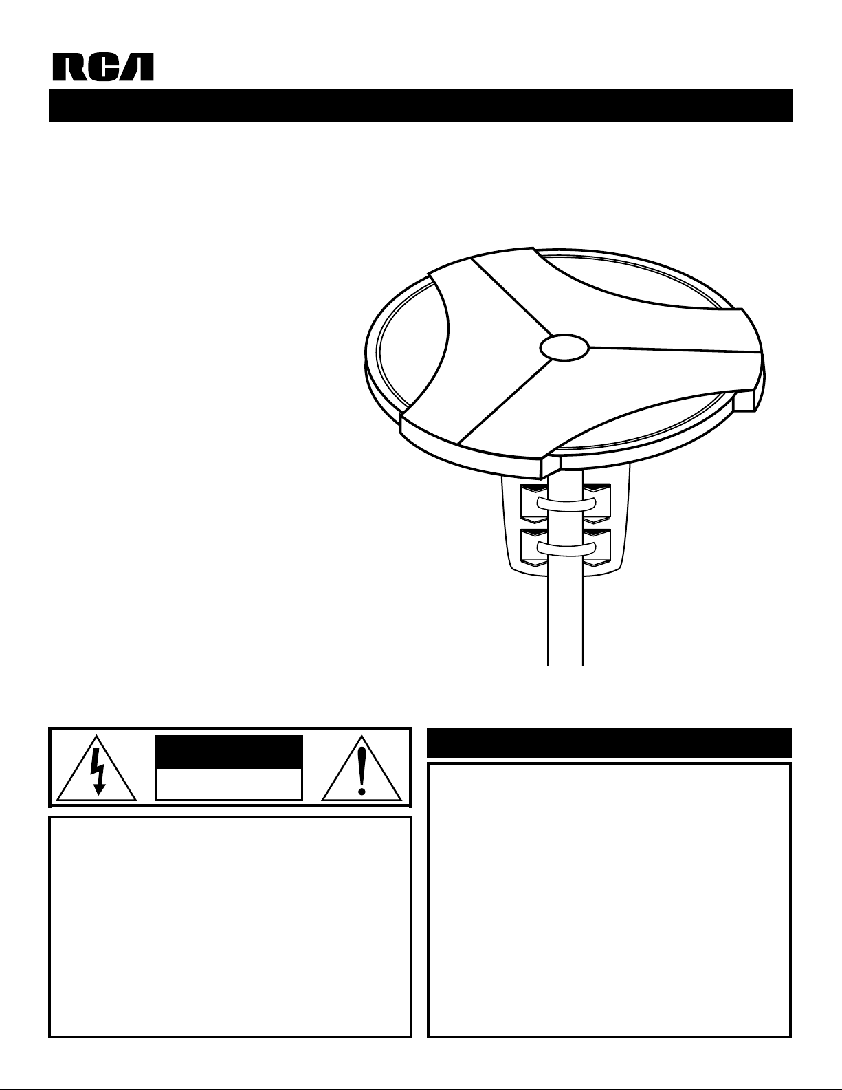
21" UHF/VHF TV Antenna
Built- In Amplifier
VHF/UHF FM Gain;20dB Average
Fixed FM Trap ( 88 -108 MHz)
UV Protected Housing
ANT2020X
Omnidirectional Antenna with Off -Air Mounting Kit
CAUTION
OPERATING INSTRUCTIONS
WARNING! USE EXTREME CAUTION WHEN INSTALLING
AN OUTDOOR ANTENNA CLOSE TO OVERHEAD WIRES.
IF THE ANTENNA STARTS TO FALL, LET IT GO! IF ANY PART
OF THE ANTENNA MAKES CONTACT WITH OVERHEAD
POWER LINES, TOUCHING THE ANTENNA, MAST, CABLE,
OR GUY WIRES CAN CAUSE ELECTROCUTION AND
DEATH. CALL THE POWER COMPANY TO REMOVE THE
ANTENNA. DO NOT ATTEMPT TO REMOVE IT YOURSELF.
Please read Important Safety Precautions
prior to installation. For your safety and con-
venience, plan each step of the installation and
purchase the necessary hardware in advance.
The order in which you perform the steps and
the hardware required depends on the mounting and connection methods you choose. We
recommend two people assemble the entire
antenna on the ground, then mount the assembled antenna on the mast.
Before You Begin
Page 2
This antenna system is designed to work properly when the
power injector is connected to the antenna through only
75-ohm coaxial cable.
The power injector has an indicator light to indicate that:
• DC power is supplied to the antenna
• There are no shorts in the connection between the power
injector and antenna
The coaxial cable between the power injector and the antenna is
used for:
• Carrying DC power from the power injector to the amplifier
board in the antenna
• Carrying the amplified TV signal from the antenna, through
the power injector, to the video equipment
If any devices are used in your home cabling system such as
amplifiers, splitters, combiners, matching transformers, or 300ohm cable, they must be connected only between the power
injector and your video equipment. Any devices connected
between the power injector and the antenna might cause a short
in the amplifier power source. If this happens, the injector’s indicator does not light and the signals to your video equipment
(multiple Vs or VCRs) might be significantly degraded.
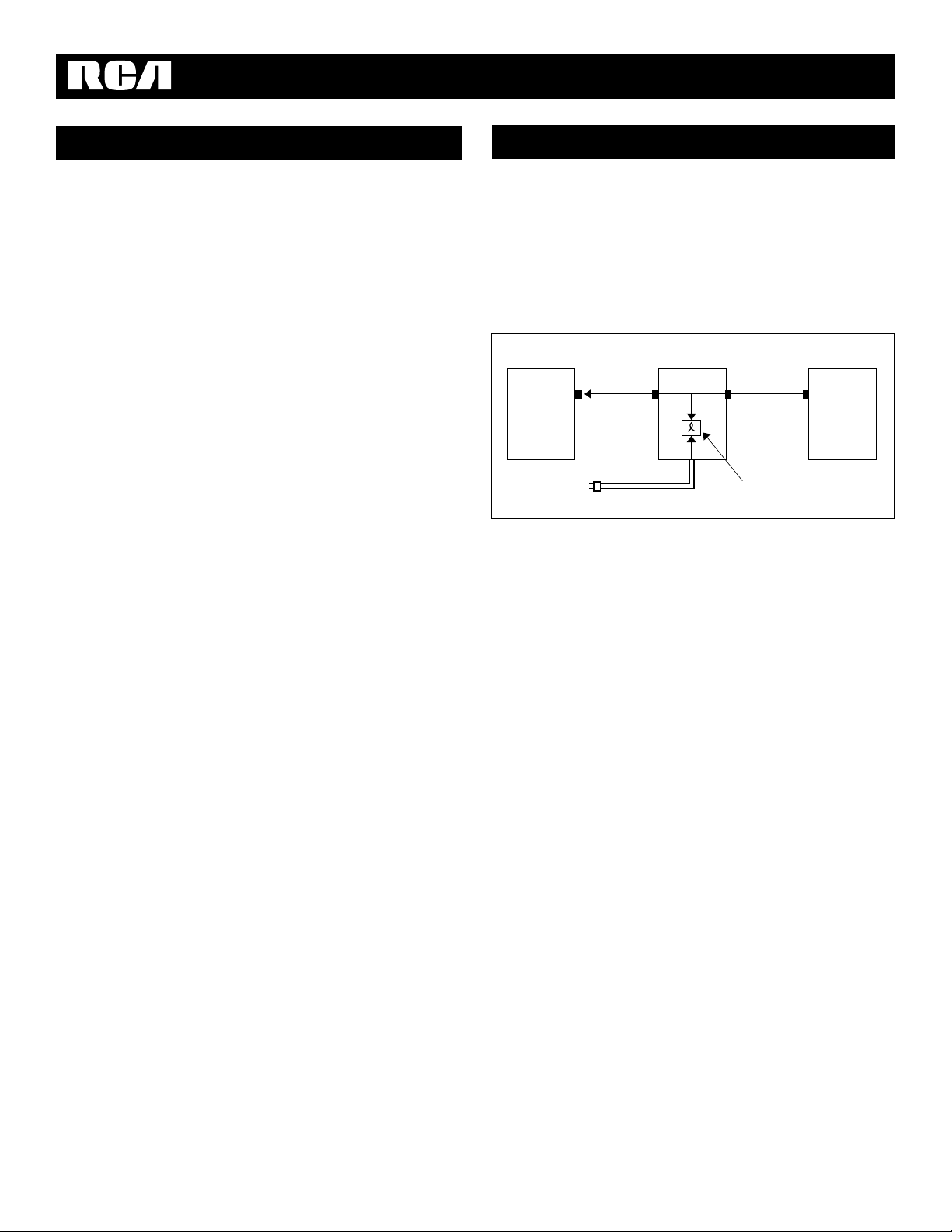
Pre-Installation Test
To make sure your antenna system works properly, perform
this test before installing it.
1. Connect a temporary 75-ohm cable between the power
injector ’s F - Connector and the antenna’s F-connector.
Note: If installing new lead-in cable, use the actual cable to
be used in the installation.
2. Connect the power injector’s TV cable to your TV’s
VHF/UHF 75-ohm F-connector.
3. Insert the supplied AC adapter’s small plug into the DC 12V
jack on the power injector.
Note: If installing the antenna in a motor home, we
recommend you use a DC cord (not supplied).
4. Plug the supplied AC adapter into a standard AC outlet.
If the power injector ’s indicator lights, the antenna is
properly connected.
Power/Short Indicator
TV Signal
Antenna
Power InjectorVideo Equipment
Important Antenna Notes
Many do-it-yourself and professional antenna installers are
injured or killed each year by electric shock. While anyone can
see the obvious danger of falling, the most resourceful people
sometimes fail to recognize overhead wires as being potentially
lethal. To touch any part of the antenna mast or guy wire to
these overhead wires is the same as touching the wires with
your bare hand. Avery serious shock is almost sure to result
when contacting an electrical wire and, in the case of primary
wires on the top of poles, the shock is like being struck by a bolt
of lightning. Many power wires are within 20 to 25 feet of the
ground and could easily be touched by an assembled antenna
and mast.
Please read and follow these important safety precautions:
• Be sure to select an antenna site well away from all overhead
wires.
• Do not try to guess which overhead wires carry high voltage.
Check with the power company.
• If you notice anything making contact with the overhead
wires, call the power company to have it removed safely.
• Do not run the downlead cable over power wires.
• Get help from a qualified professional when removing the old
antenna if there is any doubt of clearing overhead wires.
• Never install an antenna by yourself. Be sure to have at least
two people available for help, if needed.
• Never install the antenna when it is windy.
• Be sure to do all assembly work on the ground, then raise
the antenna.
• Make sure the antenna mast downlead cable is connected to
suitable lightning arrester.
• Use 8 (or larger) AWG ground wire between the mast and
the ground.
• Make sure the installation is secure. Use plenty of guy wires
and new hardware.
Important Safety Precautions
Page 3

For the best results, mount the antenna away from trees or other
obstructions. Higher frequencies are noticeably affected by these
obstructions.
The antenna is easy to install on any antenna mast or optional
light-duty mount using simple hand tools. The antenna package includes these parts:
Antenna 1
Antenna Mounting Bracket 1
Mast Clamps 2
1/4" U-Bolts 2
1/4" Split Lockwashers 4
1/4-20" Hex Nuts 4
#12 x 1/2" Long Self-Tapping Screws 4
#12 Split Lockwashers 4
Power Injector 1
AC Adapter 1
4-Piece Off-Air Mounting Kit 1
Mounting The Antenna
Outside Mounting
1. Attach the antenna mounting bracket to the bottom of the
antenna using the four #12 x 1/2" long self tapping screws
and four #12 split lockwashers
2. Attach both mast clamps, U-bolts, four 1/4" split lockwashers, and four 1/4-20 hex nuts to the mounting bracket.
Note: Do not tighten the hex nuts.
3. Plug one end of the 75-ohm coaxial downlead cable to the
antenna’s jack and seal the connection with coax sealant tape
or a weather boot.
Note: If your existing downlead is 300-ohm cable, you must
replace it with 75-ohm coaxial cable. (300-ohm cable requires a
matching transformer that significantly interferes with the
antenna’s operation.)
4. Mount the antenna on the mast, and secure it by tightening
the hex nuts evenly onto the U-bolts.
Page 4
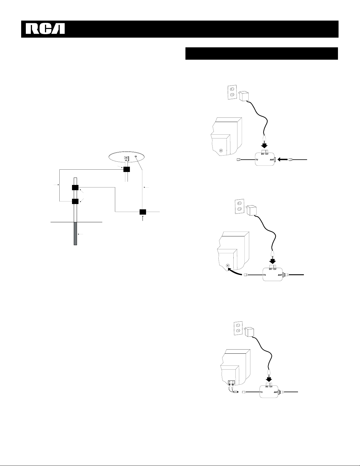
1. Connect the coax downlead from the antenna to the ANT
jack on the power injector
2. If your TV has an F connector, connect the short piece of coax
cable from the power injector to your TV’s VHF/UHF 75ohm F connector.
3. Insert the supplied AC adaptor ’s small plug into the power
injector ’s DC 12V jack. Then plug the adaptor into a standard
AC outlet. The LED on the power injector lights to indicate
that the antenna is properly connected.
If your TV has screw terminals for VHF/UHF connection,
connect a 75 to 300 ohm transformer, not supplied, between
the power injector and the VHF/UHF terminals.
Connecting The Antenna To Your TV
Inside Mounting
You can mount the antenna in an attic, closet or other out of the
way indoor location. The antenna can be mounted on a horizontal mast, closet rod, or on a short piece of mast suspended from
a roof support by a 4 inch wall mount bracket, not supplied.
Or you can simply place the antenna on a shelf in a closet. Be
sure the antenna is not in a position where it could easily fall
or be damaged.
Lightning Protection
(When Mounting The Antenna Outside)
• Ground wires for both the mast and downlead should be
copper or aluminum wire, 8 AWG or larger.
• Mount a grounding block, not supplied, as close as possible
to where the downlead enters the house.
• Downlead wire from the antenna to the grounding block and
the mast ground wire should be secured to the house with
stand-off insulators, spaced 4 - 6 feet apart.
• For a “ground - up” antenna installation, you might not need
to go around the mast if the mast extends 4 or more feet into
the earth.
Grounding Clamp
Grounding Blocks
Grounding Rod
Downlead
To T V
Lightning Arrester
Mast Ground Wire
Page 5

Specifications
Coaxial Cable Installation Precautions
• Do not bend coaxial cable into less than a 3 inch radius.
Tighter bends can cause shorts and change the cable’s
impedance.
• Do not install coaxial cable where it will have a pulling
tension greater than 50 pounds maximum. Leave no tension
on the cable after installing it.
• Use only round headed staples. Any clamps or securing
devices used with coax should grip the cable evenly about
the circumference without crushing the cable. Flat staples
can damage coax cable.
• Do not expose coaxial cable to a temperature greater than
176° (80°C). Keep the cable away from heating vents and
water heaters.
• The cable jacket withstands most outdoor environments.
However, you must seal connections and splices against
water entry.
If your TV has a 75 ohm VHF connection and a 300 ohm UHF
connection, connect a signal splitter, not supplied, between the
power injector and the TV’s VHF/UHF connections.
Bandpass:
VHF ..............................................................58-88,170-216 MHZ
UHF ........................................................................470-810 MHz
FM Trap (Fixed) ......................................................88-108 MHz
VHF/UHF Gain ..................................................20 dB Average
Impedance ..............................................75 Ohms, Unbalanced
Power Requirement ..........................12V DC 120 VAC, 60 HZ
(with supplied adaptor)
Weatherproof Housing ........UV Protected Filled Copolymer
Mounting ....................1
1
/2Inch Outer Diameter Round Mast
Specifications are typical. Individual Units might vary.
Specifications are subject to change and improvement
without notice.
Page 6

Thomson Consumer Electronics will replace this antenna if
found to be defective in materials or workmanship. Return it
postage prepaid to the address below for prompt, no charge
replacement with a current equivalent antenna.
This replacement is TCE’s sole obligation under this warranty.
TCE will not be responsible for any incidental or consequential
damages, or for any loss arising in connection with the use or
inability to use this product.
This warranty gives you specific legal rights, and you may also
have other rights which vary from State to State.
© 1998 Thomson Consumer Electronics, Inc.
Product Exchange Center, 32B Spur Drive
El Paso, Texas 79906
Assembling The Mounting Bracket
One Year Limited Warranty
Offset Mast
11" Extension
Offair Bracket
Dish Mouting Bracket
Mast Clamps
U-Bolts
Lag Bolts
Dish
Nuts
Lockwashers
#10 Self
Tapping Screw
Offset Mast
Off-air Bracket
Dish Mouting Bracket
Mast Clamps
U-Bolts
Lag Bolts
Dish
Nuts
Lockwashers
#10 Self
Tapping Screw
Swaged Tube
The ANT2020 consists of an off-air bracket and hardware, an
offset mast, and eleven inch extension, and a swaged tube for
non-vertical mounting. The bracket may be used with a satellite
dish or alone to mount this off-air antenna.
For vertical mounting, place the off-air bracket behind the Satellite
Mounting Bracket and follow the mounting instructions that came
with the satellite system. Insert eleven inch extension into offset
mast. Drill a hole through both and secure the two together with
#10 self tapping screw. With the bracket secured to the wall or
other vertical surface, mount the offset mast assembly to off-air
bracket using U-bolts, mast clamps, lockwashers, and nuts as
shown. Adjust the offset mast assembly so the off-air antenna is
horizontal and does not interfere with the DBS antenna.
The off-air bracket may be used alone to mount an off-air antenna. Mount the off-air bracket to the wall with the four lag bolts
supplied and mount the offset mast to off-air bracket as shown.
For non-vertical mounting, place the off-air bracket behind the
Satellite Mounting Bracket and follow the instructions that came
with the satellite system. With the off-air bracket secured to the
non-vertical surface, mount the swaged tube to the off-air bracket using U-bolts, mast clamps, lockwashers, and nuts shown.
Mount offset mast to swaged tube. NOTE: If additional off-air
antenna height is needed or desired, insert eleven inch extension
into offset mast. Drill a hole through both and secure the two
together with #10 self tapping screw. Adjust the swaged tube and
offset mast/offset mast assembly so the off-air antenna antenna is
horizontal and the mast does not interfere with the DBS antenna.
Drill a hole through offset mast/offset mast assembly and swaged
tube. Secure the two together with #10 self tapping screw. NOTE:
Be sure to route coaxial cable through the slot provided at top of
offset mast when making coaxial connections.
Vertical Mounting Non - Vertical Mounting
 Loading...