

Page 1
I N S T R U C T I O N S
for
UNI-DIRECTIONAL MICROPHONE
TYPE 77-A
(MI-4040)
RCA Victor Division
RCA Manufacturing Company, Inc.
Camden, N. J., U. S. A.
Copyright 1936 by the RCA Manufacturing Company, Inc.
Instructions IB-25838
Page 2
OPERATING INSTRUCTIONS
FOR
UNI-DIRECTIONAL MICROPHONE
TYPE 77-A
(MI-4040)
PART I — DESCRIPTION
1. Introduction.—e RCA Type 77-A uni-directional microphone is an entirely new type of pick-up device—a microphone
with a directional pick-up pattern wholly different from that of
any other microphone. While it resembles the velocity microphone in appearance and construction, and is, in fact, evolved
from research and development work on the latter, the RCA
Type 77-A uni-directional microphone combines the principles
of velocity and pressure operation. For this reason, it possesses
in a surprising degree the best features of each and overcomes
the disadvantages inherent in both. In view of the fact that the
unit is designed to pick up sound arriving from one direction—
or, more accurately, from one side—while almost completely
rejecting sound from the other side, it is admirably adapted to
studio pick-up, public address and sound reenforcement applications.
Instead of a diaphragm (in the commonly accepted meaning
of the word), the uni-directional microphone contains a thin
metallic ribbon suspended between the poles of a permanent
magnet with its length perpendicular to, and its width in the
plane of, the magnetic lines of force. e ribbon is rigidly
clamped at the center, as well as at the top and the bottom. e
lower half is open front and back and operated as a regular velocity microphone. In order to make the upper half of the ribbon
operate as a pressure microphone, it is, of course, necessary that
the rear of this section of the ribbon be enclosed. At the same
time it is not possible just to block this section off, as such a contrivance would result in a response increasing with the frequency. Rather, it is necessary to present an acoustic
impedance to the back part of the ribbon. An innitely long
tube would be the ideal impedance; but this, of course, is impossible. Instead, an ingenious labyrinth, which gives practically the same effect, is used. While this labyrinth has a nite
length, the desired damping of reection is obtained by ling it
very loosely with sound-absorbing material. e result is that
the upper half of the ribbon becomes an efficient pressure-operated microphone.
e vibration of each part of the ribbon is in exact accordance
with the sound vibrations and, occurring as it does within the
magnetic eld, sets up corresponding alternating electric potentials across the primary of its associated transformer. Since
the two microphones (i.e., the velocity-operated section and the
pressure-operated section of the Type 77-A microphone) are a
part of the same ribbon, the voltages developed in the two sections are, of course, in series, and the output level is obtained
from the ends of the ribbon in essentially the same manner as
in the case of the velocity microphone.
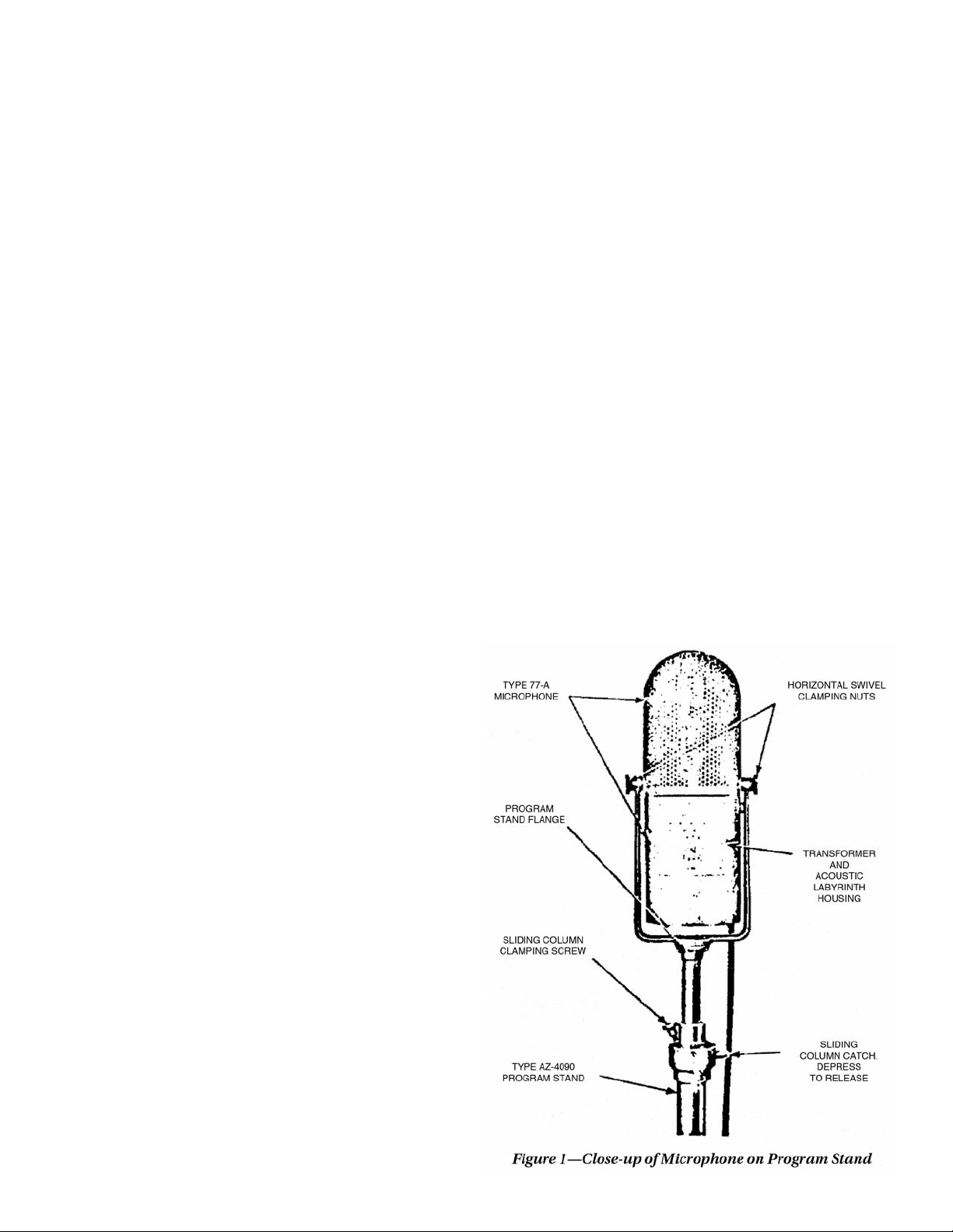
2. Description.—e uni-directional microphone shown in
Figure 1 consists of a microphone unit mounted in a horizontal
swivel on the top of a program stand. “Aiming” is accomplished
partially by means of this swivel and partially by rotating the
vertical column of the program stand. e transmitter is enclosed within a circular, perforated metal casing, so designed
as to conform to the circular construction of the labyrinth,
which occupies the lower part of the unit.
e labyrinth consists of a series of circular sections, the interior of each section having a spiral partition, an opening at the
beginning or the end of which communicates with the beginning or the end, respectively, of the section of the labyrinth that
immediately precedes or immediately follows it. e sections
occupying the upper part of the labyrinth are so designed as to
provide a cavity to accommodate the line coupling transformer,
which thus forms a part of the microphone unit.
Page 3
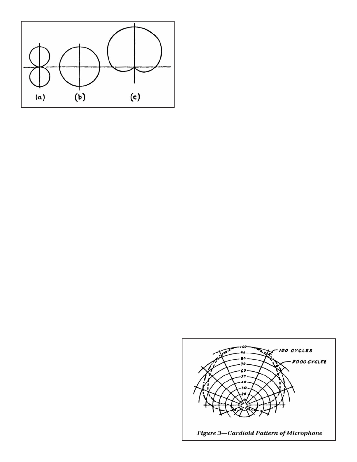
Figure 2—Development of Directional Pattern
e Type 77-A microphone unit is supported in a mounting
yoke (containing the aforementioned horizontal swivel), which
permits it to be tilted as desired. is mounting yoke is supplied
with a threaded stand ange to t a standard Type AZ-4090 program type microphone stand. A suspension mounting (Type
UP-4212-A) is supplied to permit the suspension of the unit
overhead when desired.
e microphone program stand (Type AZ-4090) is of the adjustable single vertical column type with a three-point base. e
height of the transmitter may be adjusted to maximum and
minimum heights of 84 inches and 59 inches respectively.
3. Sensitivity.—With an input sound pressure of 10 dynes per
square centimeter perpendicular in the plane of the ribbon, the
Type 77-A uni-directional microphone will deliver 317 microvolts across a 250-ohm load, which is equivalent to an output
level of –75 dB, as compared with a zero level of 12.5 milliwatts,
or –72 dB as compared with a zero level of 6 milliwatts.
On an open circuit basis of measurement, i. e., with an input
of 1 dyne per square centimeter (1 bar) perpendicular to the
ribbon, the output of the microphone on open circuit is the
equivalent of –89 dB with reference to a zero level of 12.5 milliwatts.
4. Quality of Response.—e operating range of the microphone extends from 60 cycles to 10,000 cycles. When the microphone is located less than 2 feet from the source of sound,
the low-frequency response is increased somewhat, and when
operated at a greater distance (up to 4 feet), the low-frequency
response is slightly attenuated. Beyond the 4-foot operating distance the response characteristic is unchanged by changes in
the operating distance. e frequency response is essentially
unchanged by the direction of the incident sound over an angle
of 150 degrees at the front of the microphone.
5. Directional Characteristics.—One of the most important
characteristics of the Type 77-A microphone is its uni-directional property. On the front, or operating side, of the microphone the response is very uniform, while at the rear of the
microphone sounds are attenuated an average of 20 dB, thus
giving a 10-to-1 ratio of desired to undesired pick-up. Sound
waves originating in front and along an axis perpendicular to
the plane of the ribbon will have the maximum effect.
e outstanding advantage of the Type 77-A microphone is
derived from the fact that the unit combines the action of a velocity-operated and a pressure-operated microphone, and results from the manner in which the velocity-operated and the
pressure-operated parts of the ribbon add together.
Without going into mathematical expressions for these voltages, it is possible to obtain a picture of the action from a consideration if the three patterns shown in Figure 2. In this
illustration (a) is the directional pattern of a velocity microphone, (b) is the directional pattern of a pressure microphone.
While these gures are the theoretical or idealized patterns,
they correspond, for ribbon microphones, quite closely to actual measured characteristics.
When these patterns are added, the forward lobe of the gure
8 pattern adds to the circular pattern, while the rear lobe, which
is 180 degrees out of phase, opposes. the result is the same as
that obtained when the signals of a vertical antenna and a loop
antenna are added; viz., a cardioid of revolution, as shown at
(c). In practice, the actual measured response of the Type 77-A
uni-directional microphone, as shown in Figure 3, approaches
this cardioid very closely. For all frequencies up to 6,000 cycles
the cancellation is very good. At higher frequencies a small
“tail” occurs because of the slight phase displacement that begins to become noticeable in this range.
It is at once apparent that the uni-directional characteristic is
of considerable value in the solution of some of the difficulties
encountered in reverberant locations by the reduction of the
effect of undesired sound reections, and the increased possibilities of obtaining better balance, clarity, naturalness and selectivity in sound pick-up. Extraneous direct or reected sounds
approaching the microphone from side directions and from the
rear will have little or no effect and therefore background noises
and reected sounds in the broadcast are considerably reduced, which increases, by comparison, the quality of direct
sounds reproduced. e amount of sound-proong necessary
for sound originating in the “dead zone” can be greatly reduced—and, in many cases, “dead end” construction can be
entirely eliminated.
For the same allowable reverberation pick-up, the operating
range of the uni-directional microphone is approximately 1.73
times greater than a non-directional microphone having the
same sensitivity.
When used for public address and sound reenforcement purposes, the directional characteristic is of considerable value in
reducing feedback effects between the microphone and the
loudspeaker.
Sound concentrators and baffles used with condenser microphones are unnecessary with and inapplicable to the uni-directional microphone because of the fundamental difference in
the principle of its operation.
Page 4

Figure 4—Schematic Wiring Diagram of Microphone
e transmitter must be used in free space where the ow of
air particles is unimpeded. “Pick-up” from the rear of the microphone is eliminated by the design and construction of the
unit.
PART II — OPERATION
6. Microphone Assembly.—e Type 77-A uni-directional
microphone is shipped with the stand ange attached by means
of three screws to the microphone mounting yoke. e suspension tting is shipped in an envelope in the box with the microphone unit.
(a) Stand Mounting.—If it is desired to mount the microphone
unit on a program stand, it is necessary merely to screw the microphone (using the stand ange) securely to the stand column.
See Section 9. List of Parts and Accessories, for the type of stand
recommended for this purpose.
(b) Suspension Mounting.—If it is desired to suspend the microphone overhead, the stand ange must be removed from the
microphone mounting yoke and replaced with the suspension
tting, which contains the eyelets for cord attachment. e tting must be attached securely to the yoke by means of the three
screws formerly used for mounting the stand ange.
NOTE.—When the microphone is suspended, see that its
weight is carried on the suspension tting, with no
strain on the cable.
microphones. If two microphones are placed close together, the
result will be practically zero output if their circuits are out of
phase at the overall mixer.
To check the phasing of two or more microphones connected
in a single pick-up, place the units close together, two at a time,
with the attenuators (mixers) turned to the off position. Turn on
the attenuator of one microphone to some arbitrary position
where the output will be distinctly audible or register denitely
on the volume indicator meter, if such a device is used. Talk into
the microphone and note the output volume. Now, without disturbing the setting of the attenuator of the microphone just
used, turn on the attenuator of the second microphone to the
same setting. Talk into the two microphones and note the result.
If there is an increase in volume, the microphones are in phase.
If there is a decrease in volume, remove the screen of one microphone and reverse the connections at the microphone cable
terminal board. If more than two microphones are employed,
using one microphone as a reference, check the other units
against it, one at a time, in the manner outlined above. If any
are found to be out of phase, reverse the cable connections, at
the microphone cable terminal board, of the lesser number of
microphones necessary to bring all the units into phase. A
thirty-foot cable is furnished as part of the microphone equipment. e microphone plug must be furnished by the customer.
For microphone connections refer to Figure 4, Schematic
Wiring Diagram.
(c) Cable Connections.—e microphone is shipped with the
microphone cable already connected at the microphone terminal board. is terminal board is rendered accessible for inspection or service by taking out the three screws located about the
microphone screen mounting ange and removing the screens.
(d) Phasing.—When more than one microphone is used in a
single pick-up, it is possible that the output of the of the various
microphone circuits may not be in phase when fed into a common circuit. e microphone circuits include the microphones
themselves, microphone pre-ampliers, microphone attenuators (mixers) and the necessary connecting lines. e output of
the microphone attenuators (mixers) when fed into the overall
attenuator (mixer) must be in phase, or varying degrees of distortion will result, depending on the relative placement of the
7. Technique of Uni-Directional Microphone Placement.—
e proper placement of the microphone is essential in order
to realize fully its inherent advantages. For this reason, the following instructions should be carefully studied, and close attention should be given to the results of any special placement,
with a view toward future improvement of technique. ese instructions can, of course, serve only as a guide, and a study
should be made to determine the best microphone placement
for each condition.
(a) General.—e Type 77-A uni-directional microphone has
a pick-up angle of approximately 150 degrees. e source of
sound, speaker, announcer, actor or musical instrument, should
not be placed closer to the microphone than 2 feet, and a distance of from 3 to 4 feet is to be preferred. At shorter distances
Page 5

there is a tendency toward accentuation of low frequencies,
which may result in making voices sound “boomy.” In this respect the use of the uni-directional microphone differs greatly
from that of the condenser microphone, with which the soloist
usually works at a distance of from 4 to 6 inches. As a point of
useful information, it may be mentioned here that the uni-directional microphone may be used as a close-talking microphone by talking in the plane of the ribbon. In this position, only
the pressure-operated part of the ribbon is used.
e placement of a speaker or musical instrument off from the
center line of the microphone will in no way affect the quality
of pick-up, but will merely attenuate the direct sound pick-up,
thereby raising the ratio of reverberation to direct pick-up.
e microphone is uni-directional. Speakers, instruments or
players may be placed on the operating side of the microphone
only. e diagrams (Figures 5, 6, 7, and 9) will serve as examples
which arise from the uni-directional characteristic.
For more satisfactory results, the microphone should not be
placed closer than 3 feet to any solid reecting surface. is
statement is, of course, general and specic conditions may require otherwise.
e diagrams referred to in the subsequent paragraphs and
the discussion concerning them can only serve to indicate some
of the possible placements under particular conditions. e
nal decision as to what constitutes the proper placement must
rest with someone who is competent to judge the quality of the
results as reproduced by the monitor speaker.
(b) Soloist with Piano.—Interesting effects may be obtained
by changing the angle of the microphone with respect to the
piano, thus changing the ratio of reverberation to direct pickup. e distance between the soloist and the microphone
should be determined by the strength of his (or her) voice, and
the piano should be placed accordingly. e general arrangement is shown in Figure 5. Under no condition should the
soloist be less than 2 feet from the microphone.
(c) Stage Plays.—In the case of stage plays and those pick-ups
of the type that occur in the case of auditorium-type studios,
where a sizeable audience is present—and in remote pick-ups
at theatres, night clubs and the like, where audience noise is a
serious problem, the use of the uni-directional microphone
possesses a distinct advantage. By placing the microphone with
its dead side toward the audience and close to the footlights, or
in an equivalent position, the 20-dB discrimination will provide
the desired attenuation of audience noise, while the broad pickup angle—useful through nearly 150 degrees—will afford pickup of the whole stage, or that part of the studio where the artists
are located. See Figure 6.
(d) Dance Orchestra.—e set-up for dance orchestra is similar to that just outlined for stage plays, the dead side of the unidirectional microphone being toward the dance oor. e
diagram (Figure 7) is self-explanatory, the only precaution necessary being to keep the soloist at least 2 feet, and preferably 3
feet, from the microphone.
In locating the microphone with respect to an orchestra, care
should be taken to avoid reected pick-up from hard-surfaced
oors. Such reections can be avoided by the use of carpets or
similar material on the oor.
(e) Large Orchestra.—An arrangement for a large symphony
orchestra is shown in Figure 9. It is to be noted that the wide
angle of coverage (150 degrees) of the uni-directional microphone will permit a satisfactory pick-up in many cases, such as
that shown, with but one microphone. It must be borne in
mind, however, that the physical proportions and acoustic
properties of the studio have a direct bearing on the arrangement of the orchestra and placement of the microphone. Where
space considerations do not govern, changes from the arrangement shown should not necessarily be very extensive in order
to give excellent results under the usual acoustic conditions.
(f) Public Address.—For public address use, the microphone
can usually be placed near the loudspeakers (within 3 or 4 feet).
It is important to see that the dead side of the microphone is toward the loudspeaker system—more specically, the microphone should not be placed in front or directly behind the
loudspeakers to prevent acoustic feedback. If the speaker must
have latitude of movement on the stage, it may be necessary to
have a microphone installed at each side to obtain satisfactory
pick-up.
(g) Sound Reenforcing.—Microphones used for this purpose
must generally be concealed and may be successfully operated
in the wings, ys, etc., or at the front of the stage, where some
simple method may be devised for their concealment. Such a
system usually requires the use of a number of microphones
Figure 5—Soloist with Piano Figure 6—Plays Figure 7—Dance Orchestra
VARIOUS MICROPHONE ARRANGEMENTS
Page 6

and their detailed location is largely determined by their exact
use, the constructional details of the stage and other conditions
so numerous as to preclude any denite statement of rules or
methods of applications. e uni-directional feature of the microphones may be utilized to great advantage in eliminating undesirable noise emanating from the audience area. It is also to
be noted that, because of the wide pick-up angle of the uni-directional microphone, fewer units of this type than of any other
will be required for proper coverage.
8. Operation.—In general, the microphone will operate satisfactorily and require very little attention. It should give the
normal output listed in Section 3.
e microphone may be suspended or it may be mounted on
a program or oor stand. is stand is adjustable as to height.
e center of the uni-directional microphone may be located
at any height from 59 to 84 inches above the oor. In order to
raise or lower the stand, the vertical column clamping screw
should rst be loosened. If it is desired to raise the microphone,
all that is necessary is to lift it to the desired point and there it
will lock itself automatically. Usually, it will remain xed at this
position unless there is vibration or the microphone and stand
are moved around. is moving may cause the stand to slide
slowly downward. the clamping screw is provided in order to
prevent this. However, if the microphone does not tend to creep,
it is not necessary to use the clamping screw. When it is desired
to lower the microphone stand, the clamping screw should rst
be loosened, then the inner tube of the microphone stand
should be raised slightly while pressing the sliding column latch
which projects at the side of the locking device. is will release
the lock and allow the microphone to be lowered to the desired
position, at which point the latch should be released and the
stand will automatically lock itself. en the clamping screw
may be tightened if desired.
It is not recommended that the customer attempt to repair the
microphone, but, rather, that it be returned to the RCA MANUFACTURING COMPANY, INC., for repair. is may be done by
writing to the RCA Manufacturing Company, Inc., for a “RETURNED APPARATUS” tag and “REPORT BLANK.” Before
doing this, however, make absolutely certain that the trouble is
in the microphone and not elsewhere in the circuit.
Figure 8—Plugs and Receptacles
9. List of Parts and Accessories.—
Description Type Stock No.
Uni-Directional Microphone. . . . . . . . . . . . . . . . . . . . . . . . . . . . . . . . . . . . . . . . . . . . . . . . 77-A MI-4040
Program Stand. . . . . . . . . . . . . . . . . . . . . . . . . . . . . . . . . . . . . . . . . . . . . . . . . . . . . . . . . . . . . AZ-4090 MI-4056
Suspension Fitting . . . . . . . . . . . . . . . . . . . . . . . . . . . . . . . . . . . . . . . . . . . . . . . . . . . . . . . . . UP-4212-A MI-4071-A
Stand Flange . . . . . . . . . . . . . . . . . . . . . . . . . . . . . . . . . . . . . . . . . . . . . . . . . . . . . . . . . . . . . . 16857
Microphone Screen Assembly. . . . . . . . . . . . . . . . . . . . . . . . . . . . . . . . . . . . . . . . . . . . . . . 16856
Swivel Clamping Nut . . . . . . . . . . . . . . . . . . . . . . . . . . . . . . . . . . . . . . . . . . . . . . . . . . . . . . . 16478
Washer (used under Swivel Clamping Nut). . . . . . . . . . . . . . . . . . . . . . . . . . . . . . . . . . . 16827
Microphone Cable . . . . . . . . . . . . . . . . . . . . . . . . . . . . . . . . . . . . . . . . . . . . . . . . . . . . . . . . . MI-62*
Microphone Plug . . . . . . . . . . . . . . . . . . . . . . . . . . . . . . . . . . . . . . . . . . . . . . . . . . . . . . . . . . Cannon Type P3-CG-12 MI-4630
Female Cord Connector . . . . . . . . . . . . . . . . . . . . . . . . . . . . . . . . . . . . . . . . . . . . . . . . . . . . Cannon Type P3-CG-11 MI-4620
Flush Type Wall Receptacle . . . . . . . . . . . . . . . . . . . . . . . . . . . . . . . . . . . . . . . . . . . . . . . . . Cannon Type P3-13 MI-4622
Surface Type Wall Receptacle . . . . . . . . . . . . . . . . . . . . . . . . . . . . . . . . . . . . . . . . . . . . . . . Cannon Type P3-17 MI-4621
Flush Type Wall Receptacle . . . . . . . . . . . . . . . . . . . . . . . . . . . . . . . . . . . . . . . . . . . . . . . . . Cannon Type P3-35 MI-4625
*Length of cable must be specied when ordering.
Page 7

Page 8

Figure 9—Microphone and Orchestra Arrangement for Symphony Orchestra
LEGEND
D Director F 4 Flutes T2 2 Tympani and Traps V3 8 Violas
M Microphone H1 2 Harps T3 4 Trombones V4 6 Cellos
H2 8 French Horns T4 1 Tuba V5 4 String Bass
B 4 Bassoons Ob 3 Oboes V1 12 First Violins
C 4 Clarinets T1 3 Trumpets V2 10 Second Violins Total: 75 Musicians
IB-25838 Photos of 77-A courtesy of Scott Henderson
SO-867079-4 450
 Loading...