

RCA 7587 schematic
This
signal
quencies
amplifier
Industrial Nuvistor Tetrode
In
Notediscusses
high-frequency
from
is
described.
20
Use of the
RF
to
and
the
circuits.
150
megacycles,
use
IF
of
the
Input-admittance
RCA-7587
Applications
RCA-7587
and a small
nuyistor
data
60-megacycle
tetrode
are
given
in
small-
for
fre-
wide-band
•
Tube
Design
Ti,e
a
concentric
a
top
cap
isolation,
and a low
tube
heater
micromhos
RCA-7587
from
construction
buildup
drain
tion.
The
The
RCA-7587
cold
output
tance
formula
the
is
merit
~m
input
approximately
for
Features
all-metal-and-ceramic
cylindrical
for
the
plate
a
low
grid~No.l-to-plate
output
at
10
particularly
bandwidth
capaci
of
produces
capacitance
an
capacitance
provides
of
leakage
,of
150
milliamperes,
milliamperesofplate
useful
figure
has a cold
tance
10,600
operating
nlicromhos.
a
nominal
for
9
micromicrofarads.
tube
RCA-7587
open-ended
connection
of
extremely
paths,
for
of
meri t GB
GB
=
input
C
out
capacitance
of
figure
a
tube
is
sharp-cutoff
cantilever
provides
capacitance
1.4
micromicrofarads.
low
and a rugged
the
high
current,
general
2TT
(Cin + Coutl
1.
4
Substitution
of
in a socket
162
megacycles.
industrial
for
a
gm
micromicrofarads
meri t of
C.onsequently,
construction.
excellent
of
residual-gas
internal
transconductance
and
its
tetrode
Cin
of
6.5
of
these
214
under
nuyistor
0.01
currents,
structure.
small
and
military
is
gi
micromicrofarads,
and a transconduc-
j
values
megacycles.
operating
the
tetrode
input-te-output
micromicrofarad,
In
addition,
size
yen
by
in
actual
uses
The
use
freedom
The
of
10,600
make
applica-
the
above
However,
conditions
fi~ure
of
the
low
the
a
of
Input Admittance
When
the
current
of
controlling
conductance
characteristic
©
1961
by
Radio
All
Right, Re,<,rved
Printed
in
U.S.A.
and
Carpafaho~
the
of
af
through a tube
gain
in
tile
AmerICa
of
an
the
input
circuit
ELECTRON
RADIO CORPORATION OF AMERICA, HARRISON,
isvaried,
amplifier
capacitance
connected
TUBE
as
stage,
affect
to
the
DIVISION
NEW
it
input
JERSEY
may
be
variations
the
gain-vs-frequency
of
for
the
in
the
the
tuLe.
Trademark(,; ® Regi'!ered
Marcal')
purpose
input
12.
6 1
R~gi.!radahl
r
Table
circuit
tion,
socket
Operating
Tube
Tube
Tube
Change
Change
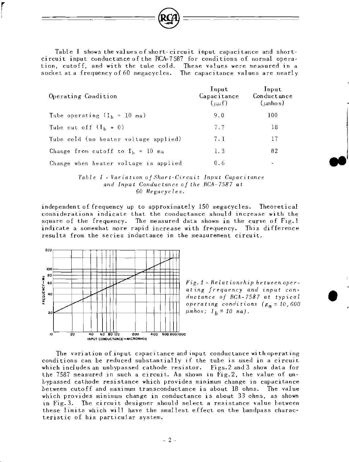
independen
I
input
cutoff,
at a frequency
operating
cut
coIn
from
when
considerations
square
indicate
results
of
a
from
shows
conductance
and
Condi
oH
( I b
(no
cutoff
heater
Table
t 0 f
frequency
the
frequency.
somewhat
the
the
with
of
tion
( I b
=
heater
1-
VariatLon
and
indicate
more
series
values
the
60
=
10
o1
voltage
to
Ib
voltage
Input
up
inductance
of
short-circuit
of
the
RCA-7587
tuLe
megacycles.
mal
applien)
=
10
IS
of8hort-Circuit
Conductance
60
Megacycles.
to
approxima
that
rapid
The
the
measured
increase
cold.
ma
applied
conductance
in
the
input
for
conditions
These
The
capaci
Capacitance
Input
of
the
RCA-7587
tel y 150
data
wi
shown
th
frequency.
measurement
capacitance
values
tance
Input
( !-'!-'f)
9.0
7.7
7.
1.3
0.6
megacyd
should
of
were
values
1
Capacitance
at
es.
increase
in
the
This
circuit.
and
normal
measured
are
Input
Conductance
(pmhos)
100
18
17
82
Theoreti
with
curve
of
difference
short-
opera-
in
nearl
Fig.l
a
y
....
cal
the
200
100
2
80
I
60
>
~
w
,
40
o
w
~
0/
2
10
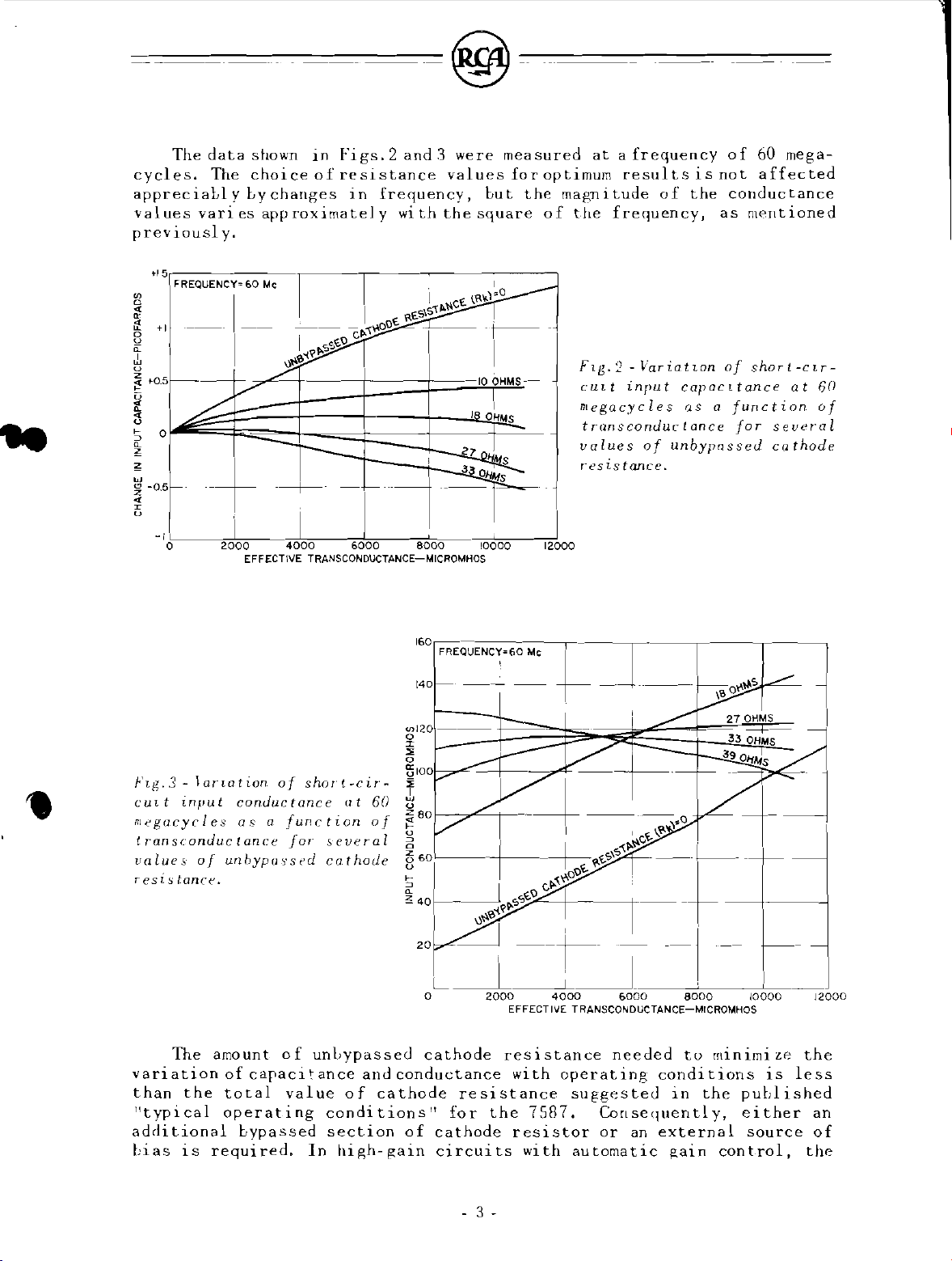
The
conditions
which
the
includes
7587
Lypassed
between
which
in
these
provides
Fig.3.
limits
teristic
/"
I I
40
60
20
INPUT CONDUCTANCE-MlCROMHOS
vari
at
can
measured
cathode
cutoff
80
ion
of
Le
reduced
an
unbypassed
in
resistance
and
minimum
The
circuit
which
of
his
particular
100
200
inpu t capaci
substantially
such a circui
maximum
transconductance
change
designer
will
have
system.
V
400
tance
cathode
which
in
should
the
Fig.1 -Relationship
ating
ductance
operating
!-,mh08" I b = 10
600
800
1000
and
inpu t conductance
if
resistor.
to
As
shown
provides
conductance
select
smallest
frequency
the
in
minimum
is
is
a
effect
of
conditions
tube
is
Figs.2
Fig.2,
change
about
aLout
resistance
on
the
and
RCA-7587
ma).
wi
used
and 3 show
the
in
18
ohms.
33
ohms,
value
bandpass
between
input
at
(gm
th
typical
==
operat
oper-
con-
10,600
in a circuit
data
value
of
capacitance
The
value
as
shown
between
charac-
•
ing
for
un-
- 2 -
The
data
shown
cycles.
apprec
values
previousl
"5r--------,-----,---~-------,
U) j
~
lr
4
~
+1
The
iaLl
varies
y.
FREQUENCY'"
choice
y Ly
approximately
60
~
u
~
u !
~
'0.5f:;iii~~t~~~1+~~~~~~~~~~-;';ala;HM:s~-:-.
~
" a
~
~
-a.5--+-
G
-I~J,=-·
o
+
2000
EFFECTIVE TRANSCONDUCTANCE-MICROMHOS
changes
Mc
,c.t:>-1''r'O
~~-(Y'fl.SS'f.\)
4000
in
Figs.2
of
resistance
infrequency,
_1
- 1 :-rs---
----,-,I~,~~~I
6000
and.3
with
I
O£.S\S
~n
values
the
:tt.t.~C€.
1-..:::;~~7
8000
were
measured
for
bu t the
square
I
~"'o
-~--1
I
I
OHMS
a:::::
10000 12000
at a frequency
optimum
magn i
of
the
FIg.2
cULt
megacycles
transconduclance
values
r'esistance.
results
tude
0 f
frequency,
-
\;'ariatLon
input
of
unbypnssed
of
60
is
not
affected
the
conduc
as
mentioned
of
shor
capacLtance
as a function
for
several
cathode
mega-
tance
l-CLr-
at
60
of
f\g.3
-
~anation.
CULt
input
megacycles
transconductance
values
resis
variation
than
T1typical
additional
bias
of
tonef::'.
The
the
is
unbypassed
amount
of
total
operating
required.
of
shor!-cir-
con.ductance
as
a
function
for
of
unLypassed
capacitance
value
bypassed
In
at
60
of
several
cathode
and
of
cathode
conditions
section
high-gain
IGa
FREQUENCY'Ga
140
---
Ull20
---
~
!,oa
!
80
~
60
~
~
~
40
~
\,}~'?>-tY'~
2a~--t---
L---.1
o
cathode
conductance
resistance
l
!
for
of
cathode
circuits
Mo
I
-~-I
--
t-
-J----
I
__
I-t-
---+
+-_~I'~'\'<~~C~
-
-,.0
,I'
C~-{,,'t(..O\)
<:JCj,~~\)",,-+-----+
,~
2000
the
4000
EFFECTIVE TRANSCONDUCTANCE-MICROMHOS
resistance
with
operating
7587.
resistor
with
&000
needed
suggested
Consequently,
or
an
automatic
conditions
external
gain
_f-I
8000
tu
in
\~
Ot\'-'S
27
--
33
39~
~
minimi
the
published
either
control,
~
~
OHMS
--
OHMS
1-
I
1-
I
10000
ze
is
source
-I
I
-0---
l
-----.j
12000
the
less
an
of
the
- 3 -
 Loading...