

Page 1
Page 2
..
•
•
Information
liable.
However,
nOT
for
parties
implication
any
which
furnished
no
infringements
may
or
result
otherwise
by R CA
respon!libility
from
under
of
any
- 2 -
is
believed
is
assumed
patentg
its
use.
patent
to
be
accurate
by
or
No
ReA
other
license
or
patent
Supersedes
rights
is
rights
and
for
its
of
granted
of
2CW4,
re-
use;
third
by
ReA.
2CW4.
6CW4
6CW4.
issue
13CW4
dated
11-62
7-62
Page 3
RCA-2CW4, 6CW4, 13CW4
•
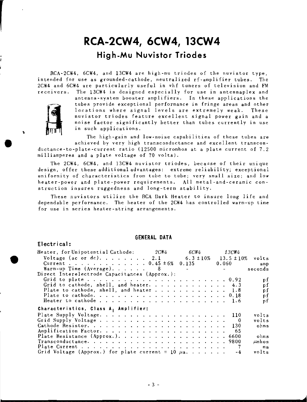
RCA-2CW4,
intended
2CW4
receIvers.
ductance-to-plate-current
milliamperes
The
design,
uniformity
heater-power
struction
These
dependable
for
use
and
for
6CW4
2CW4,
offer
in
6CW4,
use
as
are
The
13CW4
antenna-system
tubes
locations
nuvistor
noise
in
such
The
achieved
and a plate
6CW4,
these
of
characteristics
and
insures
nuvistors
performance.
series
High-Mu
and
13CW4
grounded-cathode,
particularly
is
designed
booster
provide
factor
applications.
high-gain
additional
plate-power
ruggedness
heater-string
where
triodes
by
very
and
utilize
exceptional
significantly
ratio
voltage
13CW4
The
Nuvistor
are
high-mu
useful
especially
amplifiers.
signal
feature
and
low-noise
high
heater
transconductance
(12500
of
70
nuvistor
advantages:
from
the
tube
requirements.
and
long-term
RCA
of
arrangements.
Triodes
triodes
neutralized
in
vhf
performance
levels
excellent
better
micromhos
volts).
Dark
the
are
capabilities
triodes,
extreme
to
tube;
stability.
Heater
2CW4
of
rf-amplifier
tuners
for
than
of
use
In
these
in
fringe
extremely
signal
tubes
and
at a plate
because
reliability;
very
All
metal-and-ceramic
to
insure
has
controlled
the
nuvistor
television
in
antennaplex
applications
areas
power
currently
of
these
excellent
current
of
small
tubes.
weak.
gain
their
exceptional
size;
long
warm-up
type,
and
and
other
These
and
in
tubes
transcon-
of
unique
and
con-
life
time
The
FM
and
the
a
use
are
7.2
low
and
•
Elect
Heater,
r i ca1:
Voltage
for
Unipotential
lac
Current.
Warm-up Time
Direct
Grid
Grid
Plate
Plate
Heater
Characteristics,
Plate
Grid
Cathode
Amplification
Plate
Transconductance.
Plate
Grid
Interelectrode
to
plate
to
cathode,
to
cathode,
to
cathode.
to
cathode
Supply
Supply
Voltage.
Resistor.
Resistance
Current
Voltage
or
de).
(Average).
.
shell,
Class
Voltage.
Factor.
(Approx.).
.
(Approx.)
Cathode:
Capacitances
and
shell,
and
AI Ampl
for
plate
GENERAL
0.45
(Approx.):
heater.
heater
ifier:
current
- 3 -
2CW4
2.1
8
DATA
±6%
= 10
6CW4
6.3 ± 10%
0.135
fLa.
13CW4
13.5±10%
0.060
0.92
4.3
1.8
0.18
1.6
110
130
6600
9800
65
-4
0
7
volts
amp
seconds
pf
pf
pf
pf
pf
volts
volts
ohms
ohms
f-lmhos
ma
volts
Page 4

2CVV4,
6CVV4,
13CVV4
Mechan
Operating
Maximum
Maximum
Maximum
Envelope.
Base
Maximum
PLATE
PLATE
GRID
PLATE
ica1:
Position.
Over-all
Seated
Diameter.
.•
Ratings,
SUPPLY~VOLTAGE.
VOLTAGE
VOLTAGE:
Negative-bias
Peak
positive
DISSIPATION:
Height
.
value
value
With a minimum
of
5000 ohms.
For
lower
CATHODE
PEAK
HEATER-CATHODE
Heater
Heater
values
CURRENT
negative
positive
. . . . . . . . .
Typical Operation:
Plate
Grid
Grid
Amplification
Plate
Transconductance.
Plate
Voltage
Supply
Voltage
Resistor
Resistance
Current
. .
. . . 47000
Factor.
.
Length
Medium
Des1ln-Hax1mum
series
of
series
plate-circuit
plate-circuit
VOLTAGE:
with
with
respect
respect
(Approx.).
Ceramic-Wafer
Values:
resistance
to
cathode
to
cathode
Twelvar
resistance
5-Pin
300·
135
1.5
Operating
100 max.
100
5440
12500
7.2
Metal
(JEDEC
max.
max.
55
max.
max.
0
max.
See
Considerations
15
max.
max.
70
o
68
. .
Any
0.8"
0.625
0.440"
Shell
No.E5-65)
volts
volts
volts
volts
watts
Fig.l
and
ma
volts
volts
volts
volts
ohms
ohms
f-lJ!lhos
ma
"
r
,
•
Maximum
Grid-Circuit
For
For
• A
sistance
volts
•
For
Circuit
fixed-bias
cathode-bias
plate
supply
under
operation
Resistance:·
and
agc
conditions
at
Values:
operation.
voltage
voltage
metal-shell
operation.
of
300
are
of
maximum
used
temperatures
OPERATING
The
base
Co.
socket
socket
No.E5-65
designation
used
Use
maximum
Nos.Nu 5044 and
In
some
in
nuvistor
of Plate-Dissipation Rating Chart
The
Plate-Dissipation
rated
ptns
No.133
previous
socket.
which
plate
of
the
2CW4,
65 10 001 and
Nu
publications
This
defines
tubes.
dissipation
number
the
RatingChart
volts
to
rated
may
limit
plate
CONSIDERATIONS
6CW4,
the
5060,
or
is
not
JEDEC Medium
of
the
be
used
the
dissipation
up
to
and
Industrial
their
reference
a
shown
2CW4,
provided
voltage
1350 C.
13CW4
at
fit
equivalents.
has
socket
Ceramic-Wafer
6CW4,
in
Fig.l
designation
and
0.5
2.2
sufficient
the
plate
(1.5
watts).
the
Cinch
Electronic
been
Twelvar
presents
13CW4
for
max.
max.
plate-circuit
of
the
tube
Manufacturing
Hardware
made
but
to
is
5-pin
graphically
various
megohm
megohms
re-
to
135
Co.
a
JEDEC
a
base
base
the
minimum
•
1
1
- 4 -
Page 5

2CVV4,
6CVV4,
13CVV4
•
values
ation
plate
Al
IS
a
given
ating
required
voltage
of
watts.
dissipation
of
is
voltage
amplifier
equivalent
To
determine
1.
conditions.
2.
Example:
130
volts
serIes
bounded
set
of
From
From
minimum
of
-1
The
required
is
plate-circuit
by
the
=
135
volts,
service,
to
the
cathode
the
o~rating
Fig.2,
Fig.l
volt,
and a plate
Average
determine
value
(a)
From
the
(b)
From
minimum
3700 ohms.
lines
and
because
required
conditions:
of
series
Fig.2
corresponding
Fig.l
current
resistance.
representing
plate
no
grid
current
minimum
Plate
the
corresponding
plate-circuit
-
-
series
current
current
rating.
series
Characteristics,
for a plate
plate
the
plate
of
10.5
milliamperes
plate-circuit
Et
=6.3
VOLTS
The
regIon
plate
flows,
voltage
dissipation
dissipation
=
15
plate-circuit
maximum
resistance.
current
resistance
of
permissible
milliamperes.
the
plate
select
of
the
plate
is
dissipation
130
volts
10.5
for a plate
is
approximately
=
1.5
In
current
resistance
desired
and a grid
milliamperes.
for
this
<.'
.
oper-
watts,
class
rating
for
oper-
and
voltage
1.
plate
37
•
1.61--+-+-+--4-j--+-+-+--i-j--+-+--l.._-j
, I
hr-t----1-+-+--+-{}'-->l-r/t7+,....,..,..,,5OQO
I-t-+--+-+-+-f--
1.4
~
I-
12
~.
I M
~
~
I 1 0
~
0.'
~
~ ~
0.'
"
-
0.4
0'j;.o/q i/-j-+-++--+-f---+-+1--1
0.2 135
lJ
20
40
Fig.1 -Plate-Dissipation
for
Types
"'~';/////~"
JI//,
;,//
f///
~~
~-:,
~'i/
0/./
60
PLATE
2C1f4. 6C1f4.
~ ~
{J"';
if:/
'"I!';
$/'////
//
//
/
f/
/ / ../
../
80
VOLTS
'/
'¥.
....
/
/
)~
/
./
/../
100 120 140
92CM-II&81
Rating
and
13C1f4.
4000
l
"""'~
2000~
~
IOOO~
~
~
~
~
~
Z
Chart
~
0
,
.,
. ,
.
~
,.
0
~
~
"
~
w
•
"
"
S
·t->:=-
o 0
N
N
PLATE MILLlAMPERES
2
9ZCIll~IO~24RI
o
Fig.2 -Average
for
Type
13Clf4
- 5 -
6Clf4
Except
Plate
and
for
Characteristics
for
Types
Heater
Voltage.
2Clf4
and
Page 6

2CVV4,
~
~
~
~
w
~
~~
w
~
~
~
~
~
w
~
w z
c(
•
6CVV4,
004
%
'D
0
4
'"
E
'!o\~
-Average
6CW4
Except
0.03
0.02
0.01
Fig.3
Type
13CW4
13CVV4
0
'02
1
3
,00
GRID
and
0
0
-2
VOLTS
Characteristics
for
Types
for
Heater
0
'"
::-
,,,s
'"
-I
92(;M-IO~2.0RI
2CW4
Voltage.
",0
60
70
60
50
40 " ([
30
.
20000
15000~
OOOOw
5000~
0
for
and
}.
~
o
t;
~
z
0
5
~
~
DIMENSIONAL
MT4
METAL
SHELL
BASE
JEDEC
N!:!
E~-65
•
100"
ALONG
IN
ZONE
.130"MAX.
LARGE_
LUG
I:
MAXIMUM
0.190"
2:
SHELL TEMPERATURE SHOULD
'A'.
~
0
I
~
u
~
I
E
u
z
~
u
0
0
0
u
~
~
,
NOTE
NOTE
..----Trn--rr---,n,
MIN.
l.--.435 " MAX.
(NOTE
e=SHORT
CONNECTION-DO NOT USE
0.0.
LUG
LENGTH.
OUTLINE
DIA.-J
I)
PIN-INTERNAL
OF
D.UUD"
_L
--r
ZONE
(NOTE 2)
CERAMIC
/WAFER
'I>!
SMALL
LUG
92CS-I0970R2.
IS
PERMITTED
BE
MEASURED
.800"
MAX.
I
•
PIN
PIN
PIN
PIN
PIN
PIN
1 :
Z:
3:
U:
5:
6:
•
PLATE
•
GRID
•
•
I N
• = SHORT
BASING
(Bottom
DD
= LARGE LUG
CONNECTION--OO
PIN-INTERNAL
12AQ
DIAGRAM
View)
p
NOT
USE
PIN
PIN
PIN
PIN
PIN
PIN
7:
B:
9:
10:
11:
12
•
CATHODE
•
HEATE
OMITTED
:
HEATER
- 6 -
•
ARRANGEMENT
LARGE
R
lUli
GRID-----
OF
BASE
PINS
S¥ALL
92.CS-IIB~6
LUG
Page 7

2CVV4,
6CVV4,
13CVV4
•
SOCKET
PLANE
INDEX GUIDE
LARGE LUG
MEDIUM
INSERTION
CERAMIC-WAFER
TWELVAR
.
280
•
21O''olA
•
140"OIA
•
070'
lA.
"OIA
•
.
BASE
METAL
0
60
•
SHELL
SMALL
LUG
•
JEDEC
No.
E12-64
ES-6S
Note
I:
0.190"
Note
their
Pin
Base-pin
toLerances
without
plate
0.0350"
circles
0.0005".
holes
on
0.0700" ± 0.0005"
with a tolerance
gauge
of
0.2270"
0.4200"
circles
t
0.0005".
lug
2:
ends
11
is
gauge
located
provides
Maximum
length.
Pins
do
omitted.
positions
such
undue
having
±
0.0005"
as
follows:
three
±
±
0.0005"
at
1800 ± 0.080
NAME
l2-Pin
O.D.
1,3,5,6,7,
not
touch
5-Pin
Base
Base
of
O.440u is
and 9 are
the
PIN-ALIGNMENT
and
lug
that
force
holes
on
0.1400"
of
for
0.0005"
entire
pass
thickness
diameter
Three
located
diameter
±
0.08
two
and
diameter
into
±
0
curved
0.1450"
and
positions
length
of
located
holes
on
0.0005",
circles
for
circle
having
of
socket
GAUGE
and
a.25
0.2100"
each
slots
1,2,3,4,5,6,7,8,
2,4,8,10,12,
permitted
a
length
insertion
shall
of
pins
disengage
ft
and
on
four
located
three
at
specified
angle.
with
±
0.0005"
concentric
a
width
92CM-IQ478Rl
PINS
9,10,11,12
(Note
along
such
plane
be
held
and
lugs
from
tweLve
±
chordal
holes
concentric
on
0.2800"
O.OOOS",three
holes
In
located
of
located
additIon,
lengths
with
0.0230"
2)
the
that
.
to
will
fLat-
of
an~les
on
pin
±
- 7 -
Page 8

,
,
 Loading...