

Page 1
Television
User's Guide
Changing Entertainment.
TOCOM 161623
Page 2
Important Information
[#:lwJ |[o] _I
RISKOFELECTRICSHOCK
DO NOTOPEN
This symbol indicates that this product incorporates double
insulation between hazardous mains voltage and user
accessible parts. When servicing use only identical
replacement parts.
Caution: To reduce the risk of electric shock, do not remove cover (or back). No user serviceable
parts inside. Refer servicing to qualified service personnel.
_ This symbol indicates important A This symbol indicates "dangerous voltage" inside the
instructions accompanying the _ product that presents a risk of electric shock or
product, personal injury.
WARNING
To reduce the risk of fire or electric shock,
do not expose this product to rain or
moisture.
Theapparatus shall not be exposedto
dripping or splashingand that no objects
filled with liquids, suchasvases,shall be
placedon the apparatus.
Refer to the identifieation/rating label located on the
back panel of your product for its proper operating
voltage.
FCCRegulations state that unauthorized changes or
modifications to this equipment may void the user's
authority to operate it.
Caution: Using video games or any external accessory
with fixed images for extended periods of time can
causethem to be permanently imprinted on the
picture tube (or projection IV picture tubes). ALSO,
some network/program Iogos, phone numbers, etc.
may causesimilar damage.Thisdamage is not covered
by your warranty.
Cable IV Installer: This reminder is provided to call your
attention to Article 820-40 of the National Electrical
Code(Section 54 of the Canadian Electrical Code,Part
1)which providesguidelines for proper grounding and,
in particular, specifies that the cable ground shall be
connected to the grounding systemof the building as
close to the point of cable entry as practical.
Product Registration
Please fill out the product registration card (packed separately) and return it immediately. For U.S.
customers: Your RCAConsumer Electronics product may also be registered at www.rca.com/
produetregistration. Registering this product allows us to contact you if needed.
Product Information
Keep your sales receipt to obtain warranty parts and service and for proof of purchase. Attach it here
and record the serial and model numbers. These numbers are located on the product.
Model No. Serial No. Purchase Date:
Dealer/Addres_Phone:
Page 3
Table of Contents
Chapter 1: Connections & Setup
Things to Consider Before You Connect ....................................................................... 3
Protect Against Power Surges ........................................................................... 3
Protect Components from Overheating ........................................................... 3
Position Cables Properly to Avoid Audio interference .................................... 3
Important Stand and BaseSafety Information ................................................ 3
Use Indirect Light ............................................................................................... 3
Cables Needed to Connect Components to Your TV ....................................... 3
TV + DVD + VCR .............................................................................................................. 4
Using the VPORT Jack ..................................................................................................... 5
Explanation of Jacks ....................................................................................................... 6
The Front of Your TV ...................................................................................................... 7
Front Input Jacks ................................................................................................ 7
Front Panel Buttons ........................................................................................... 7
Plug in the TV .................................................................................................................. 7
Put batteries in the remote ........................................................................................... 7
How to Use the Remote Control to Complete the Initial Setup ................................ 8
Turn on the TV ................................................................................................................. 8
Complete the Initial Setup ............................................................................................. 8
Complete Auto Channel Search ........................................................................ 8
Chapter 2: Using the Remote Control
Button Descriptions for TV Mode .................................................................................. 9
Button Descriptions for DVD and VCR Modes .............................................................. 9
Using the INPUT Button ................................................................................... 10
Programming the Remote to Operate Other Components ....................................... 10
Find Out If You Need to Program the Remote ............................................... 10
Programming the Remote ............................................................................... 10
How to Use the Remote After You've Programmed It .................................. 12
Remote Control Codes................................................................................................. 12
Chapter 3: Using the TV's Features
Channel Banner ............................................................................................................ 14
Why You Should Use the Auto Tuning Feature ........................................................ 14
How to Set Up the Auto Tuning Feature ........................................................ 14
Parental Controls and V-Chip ..................................................................................... 15
How V-Chip Works ........................................................................................... 16
USA V-Chip Rating System ............................................................................... 16
Canadian English V-Chip Rating System ......................................................... 16
Canadian French V-Chip Rating System .......................................................... 17
Page 4
Table of Contents
USA V-Chip TV Rating Limit ............................................................................. 18
Blocking Specific Content Themes .................................................................. 19
Viewing Specific Content Themes ................................................................... 19
Blocking Canadian V-Chip Ratings .................................................................. 20
V-Chip Movie Rating Limit ............................................................................... 20
V-Chip Exempt Program Block ......................................................................... 20
KidPass .............................................................................................................. 21
V-Chip Active .................................................................................................... 21
Front Panel Lock ............................................................................................... 21
Change Password ............................................................................................. 21
Chapter 4: Using the TV's Menu System
Sound Menu .................................................................................................................. 22
Picture Menu ................................................................................................................ 22
Setup Menu .................................................................................................................. 23
Parental Control Menu ................................................................................................ 24
Time Menu .................................................................................................................... 24
Chapter 5: Other Information
Troubleshooting ............................................................................................................ 25
Care and Cleaning ........................................................................................................ 27
Limited Warranty ......................................................................................................... 27
2
Page 5

Things to Consider Before You Connect
Protect Against PowerSurges
* Connect all components before you plug any of their power cords into the wall OUtlet.
* Turn off the ]V and/or component before you connect or disconnect any cables.
* Make sure all antennas and cables are properly grounded. Refer to the important Safety Instructions
packed separatdy.
Protect Components from Overheating
* Don't block ventilation holes on any of the components. Arrange the components so that air can
circulate freely.
* Don't stack components.
* If you place components in a stand, make sure you allow adequate ventilation.
* If you connect an audio receiver or amplifier, place it on the top shelf so the heated air from it won't
flow around other components.
Position Cables Properlyto AvoidAudioInterference
* Insert each cable firmly into the designated jack.
* If you place components above the lV, route all cables down the side of the back of the W instead
of straight down the middle of the W.
* If your antenna uses 3OO-ohm twin lead cables, do not coil the cables. Also, keep the twin lead
cables away from audio/video cables.
Important Stand and Base Safety Information
Choose the location for your _ carefully. Place the ]V on a stand or base that isof adequate size and
strength to prevent the _[Vfrom being accidentally tipped over, pushed off, or pulled off. This could
cause perSonal injury and!or damage the _. Refer to the Important Safety Instructions packed
separately.
Use Indirect Light
Don't place the JV where sunlight or room lighting will be directed toward the screen. Use soft or
indirect lighting.
Cables Needed to Connect Components to YourTV
The pictures below show the cables needed for the connections represented in this book.
Coaxial cable S_Video cable
Audio/Video cables Component Video (Y,Pb,Pr) cables
Component video to VPORTcable Xbox to VPORTcable
Chapter 1 Grophics contained within this publication are for representation only. 3
Page 6
Connections Setup
VCR
TV(backpanel)
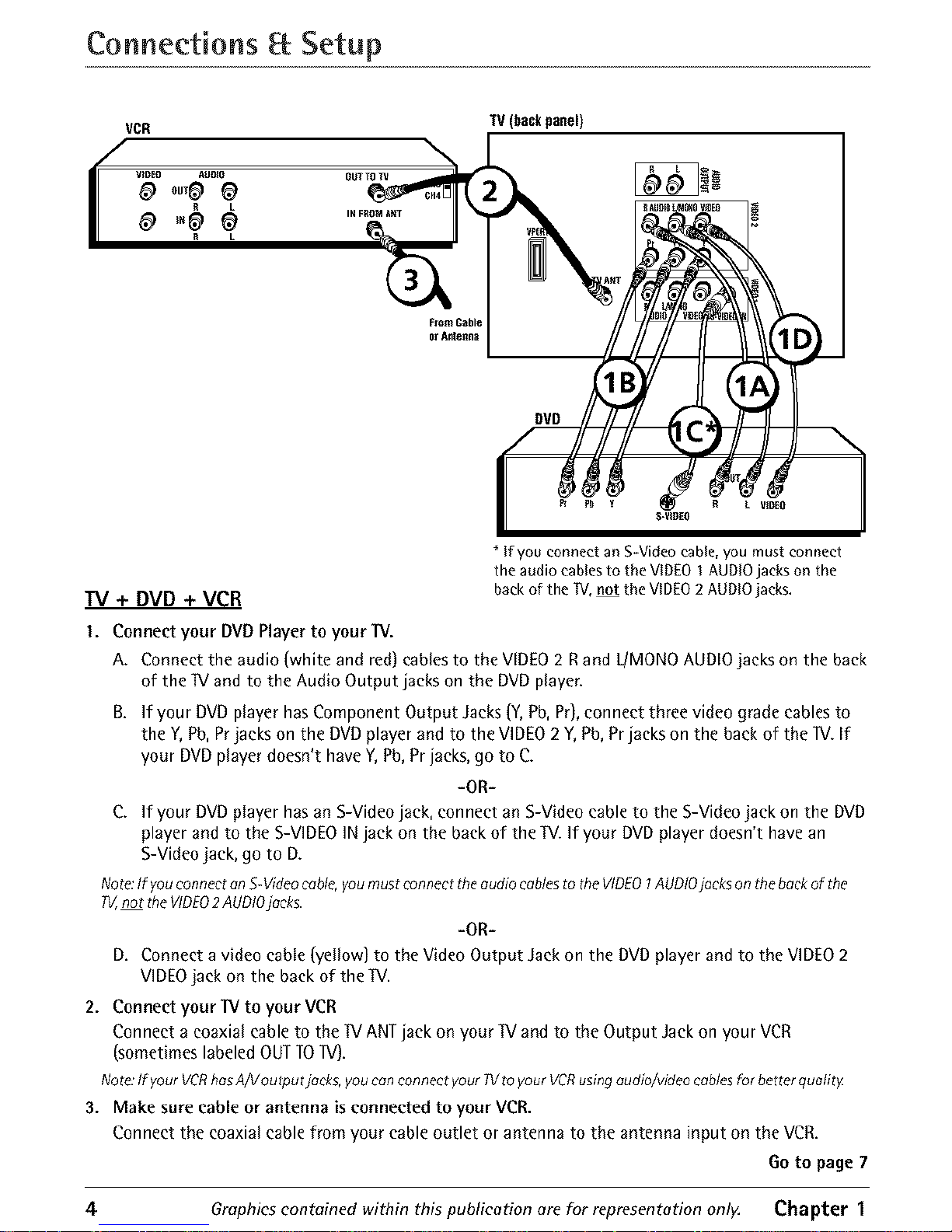
TV + DVD + VCR
* If you connect an S-Videocable, you must connect
the audio cables to the VIDEOI AUDIOjacks on the
back of the TV,not the VIDEO2AUDIOjacks.
I. Connect your DVDPlayer to your"IV.
A. Connect the audio {whiteand red) cablesto the VIDEO2 Rand L/MONOAUDIOjacks on the back
of the IV andto the Audio Output jacks on the DVDplayer.
B. ff your DVDplayer hasComponent Output Jacks{Y,Pb,Pr),connect three video gradecables to
the Y,Pb,Prjacks on the DVDplayer and to the VIDEO2 Y,Pb,Prjacks on the back of the lV. If
your DVDplayer doesn't haveY,Pb,Prjacks, go to C.
-OR-
C. If your DVD player has an S-Video jack, connect an S-Video cable to the S-Video jack on the DVD
player and to the S-VIDEO IN jack on the back of the TV. If your DVD player doesn't have an
S-Video jack, go to D.
Note:If you connectanS-Videocable,you mustconnect the audiocablesto the VIDEO1AUDIOjacks onthe beckof the
P_,not the VIDEO2AUDIOjacks.
lOR-
D, Connect a video eable (yellow) to the Video Output Jack on the DVD player and to the VIDEO 2
VIDEO jack on the back of the IV.
2. Connect your IV to your VCR
Connect a coaxial cable to the IV ANTjack on your IV and to the Output Jack on your VCR
(sometimeslabeled OUTTOIV).
Note.'lfyour VCRhosA/Voutput jocks, youcan connect yourlV toyour VCRusingaudio/video cablesfor betterquality
3. Make sure cable or antenna is connected to your VCR.
Connect the coaxial cable from your cable outlet or antenna to the antenna input on the VCR.
Go to page 7
4 Graphics contained within this publication are for representation onl)_ Chapter 1
Page 7
Connections Setup
Xbox
TV(backpanel)
or Anteflna
Component video to
VPORT cable (not
supplied)
Xbox to VPORTcable
(not supplied)
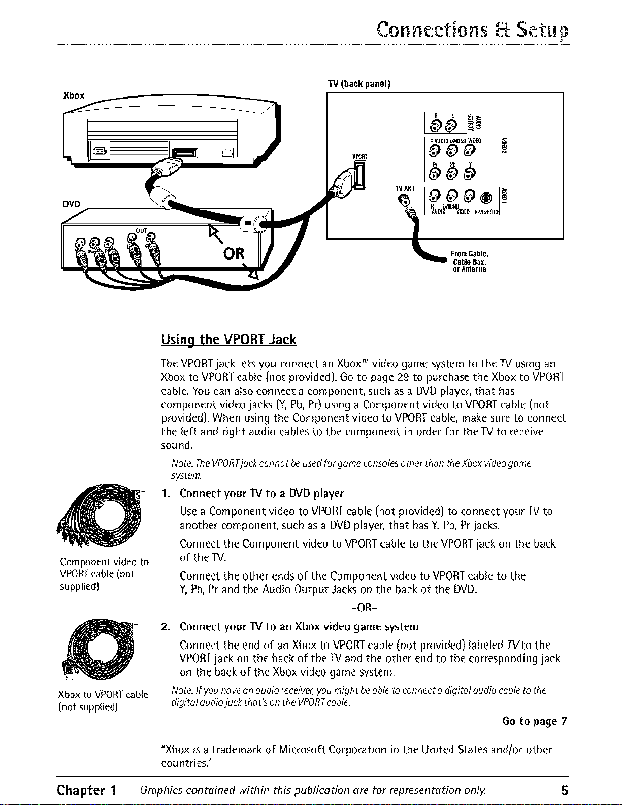
Using the VPORT Jack
The VPORTjack lets you connect an XboxTM video game system to the IV using an
Xbox to VPORTcable (not provided). Go to page 29 to purchase the Xbox to VPORT
cable. You can also connect a component, such as a DVDplayer, that has
component video jacks (Y,Pb,Pr) using a Component video to VPORTcable (not
provided). When using the Component video to VPORTcable, make sure to connect
the left and right audio cables to the component in order for the IV to receive
sound.
Note:TheVPORTjockcannot beusedfor gameconsolesother th#n the )(boxvideogame
system.
1. Connect your IV to a DVD player
Use a Component video to VPORT cable (not provided) to connect your IV to
another component, such as a DVD player, that has Y, Pb, Pr jacks.
Connect the Component video to VPORT cable to the VPORT jack on the back
of the IV.
Connect the other ends of the Component video to VPORTcable to the
Y,Pb, Pr and the Audio Output Jacks on the back of the DVD.
-OR-
2. Connect your IV to an Xbox video game system
Connect the end of an Xbox to VPORTcable (not provided) labeled TVto the
VPORTjack on the back of the IV and the other end to the corresponding jack
on the back of the Xbox video game system.
Note:Ifyouhavean audioreceiver,youmight be abletoconnectadigitalaudiocabletothe
digitalaudioj_ck that'sontheVPORTcable
Go to page 7
"Xbox is a trademark of Microsoft Corporation in the United States and/or other
countries."
Chapter 1 Graphicscontained within this publication are for representation only. 5
Page 8
Connections Setup
Explanation of Jacks
This section describes the jacks you can use to make connections. There are several
ways to connect components to your _V.
VPORT Go to the previous page for VPORTexplanation.
TV ANT Letsyou connect a coaxial cable to receive the signal from the antenna,
cable, cable box, or if using the example on page 4, a VCR.
R I./MONO
AUDIO VIDEOS-VIDEOIN
RAUDIOL/MONOVIDEO
Pr Pb Y
R L
r_
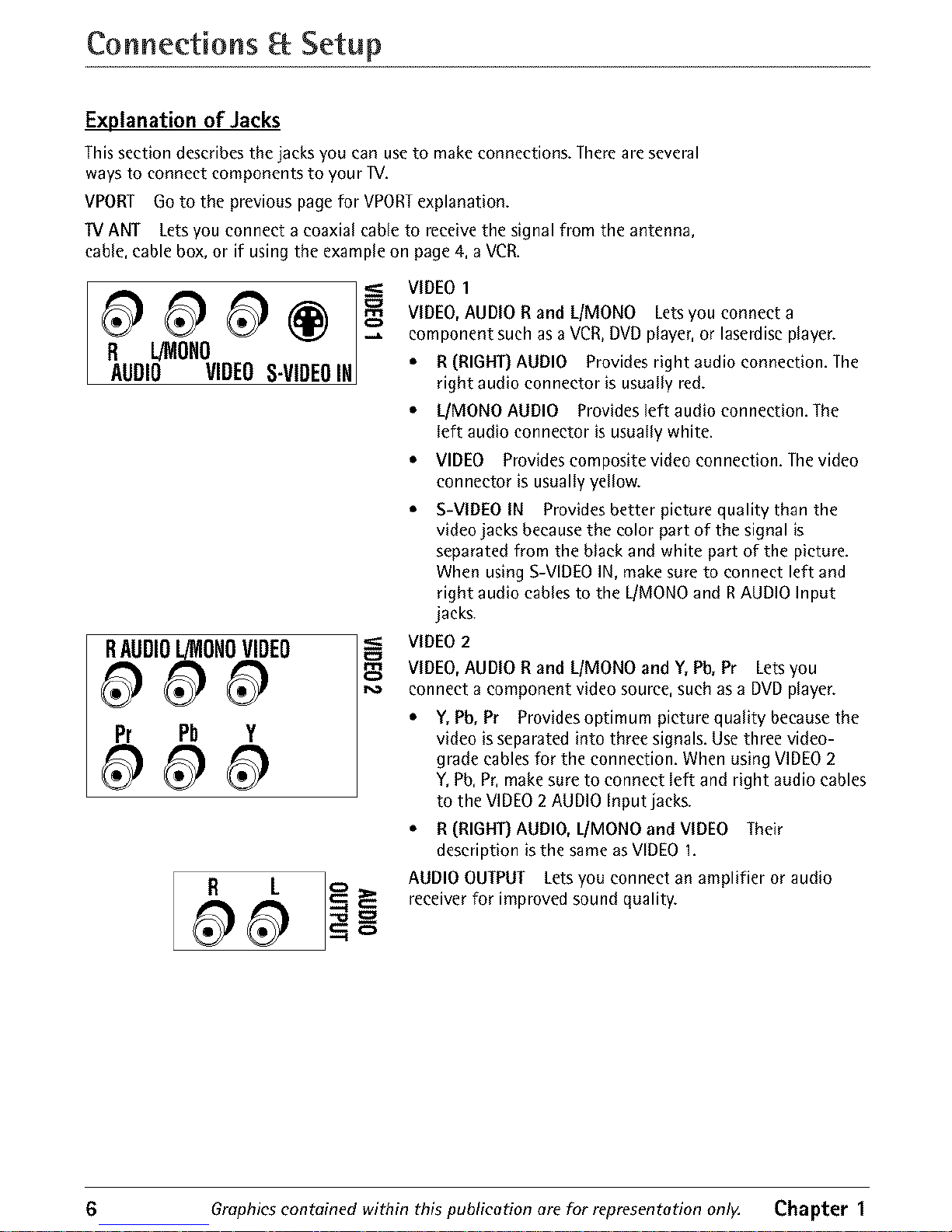
VIDEO 1
VIDEO, AUDIO R and L/MONO Lets you connect a
component such as a VCR, DVD player, or laserdisc player.
• R (RIGHT) AUDIO Provides right audio connection. The
right audio connector is usually red.
• L/MONO AUDIO Provides left audio connection. The
left audio connector is usually white.
• VIDEO Provides composite video connection. The video
connector is usually yellow.
• S-VIDEO IN Providesbetter picture quality than the
video jacks becausethe color part of the signal is
separated from the black and white part of the picture.
When using S-VIDEOIN, make sure to connect left and
right audio cablesto the L/MONOand RAUDIO Input
jacks.
VIDEO2
VIDEO, AUDIO R and L/MONO and Y, Pb, Pr Lets you
connect a component video source, such as a DVD player.
• Y, Pb, Pr Provides optimum picture quality because the
video is separated into three signals. Use three video-
grade cables for the connection. When using VIDEO 2
Y, Pb, Pr, make sure to connect left and right audio cables
to the VIDEO 2 AUDIO Input jacks.
• R (RIGHT) AUDIO, L[MONO and VIDEO Their
description is the same as VIDEO I.
AUDIO OUTPUT Lets you connect an amplifier or audio
receiver for improved sound quality.
6 Graphics contained within this publication are for representation only. Chapter 1
Page 9
Connections Setup
AUDIO
H-PHONE L_ONO R VIDEO
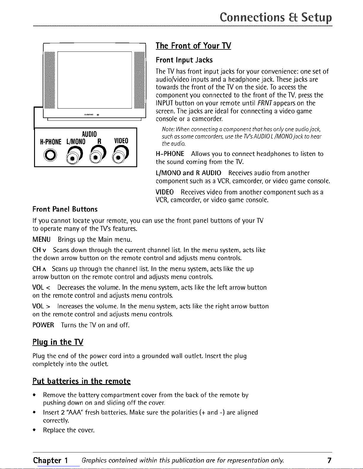
The Front of Your TV
Front Input Jacks
The lV has front input jacks for your convenience: one set of
audio/video inputs and a headphone jack. These jacks are
towards the front of the W on the side. To access the
component you connected to the front of the ]V, press the
INPUT button on your remote until FRNTappears on the
screen. The jacks are ideal for connecting a video game
console or a eameorder.
Note:Whenconnecting aeomponent thet hasonly oneaudiojack,
suchassomecamcorders,usethe TV'sAUDIOL/MONOjeck to hear
tile audio.
H-PHONE Allows you to connect headphones to listen to
the sound earning from the W.
L/MONO and R AUDIO Receives audio from another
component such as a VCR, eameorder, or video game console.
VIDEO Receives video from another component such as a
VCR, eameorder, or video game console.
Front Panel Buttons
If you cannot locate your remote, you can use the front panel buttons of your IV
to operate many of the lV's features.
MENU Brings up the Main menu.
CH v Scans down through the current channel list. In the menu system, acts like
the down arrow button on the remote control and adjusts menu controls.
CH ^ Scans up through the channel list. In the menu system, acts like the up
arrow button on the remote control and adjusts menu controls.
VOL < Decreases the volume. In the menu system, acts like the left arrow button
on the remote control and adjusts menu controls.
VOL > Increases the volume. In the menu system, acts like the right arrow button
on the remote control and adjusts menu controls.
POWER Turnsthe 1V on and off.
Plug in the TV
Plug the end of the power cord into a grounded wall outlet. Insert the plug
completely into the outlet.
Put batteries in the remote
* Remove the battery compartment cover from the back of the remote by
pushing down on and sliding off the coven
* Insert 2 "AAA" fresh batteries. Make sure the polarities (+ and -) are aligned
correctly.
* Replace the coven
Chapter 1 Graphicscontained within this publication are for representation only. 7
Page 10
Connections Setup
button
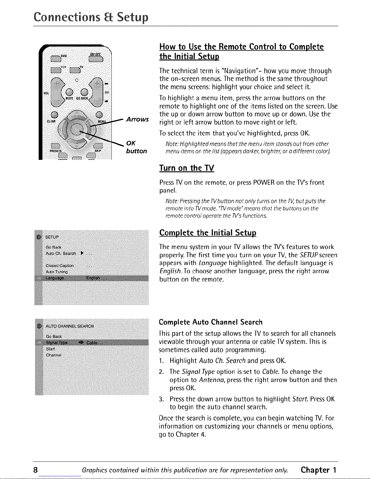
How to Use the Remote Control to Complete
the Initial Setup
The technical term is "Navigation"- how you move through
the on-screen menus. The method is the same throughout
the menu screens: highlight your choice and select it.
To highlight a menu item, press the arrow buttons on the
remote to highlight one of the items listed on the screen. Use
the up or down arrow button to move up or down. Use the
right or left arrow button to move right or left.
To select the item that you've highlighted, press OK.
Note:Highlighted meansthat themenuitem stands out from other
menu items on the list (appearsdarker,brighter,or a different color]
Turn on the TV
Press IV on the remote, or press POWER on the Iv's front
panel.
Note:PressingtheW button not only turns on the _, but puts the
remoteinto Wmode. "TVmode"meansthat thebuttons on the
remotecontroloperatethe 1V'sfunction&
Complete the Initial Setup
The menu system in your 1Vallows the IV's features to work
properly. Thefirst time you turn on your IV, the 5ETUPsereen
appearswith Language highlighted. The default language is
English.Tochoose another language, pressthe right arrow
button on the remote.
Complete Auto Channel Search
This part of the setup allows the IV to search for all channels
viewable through your antenna or cable IV system. This is
sometimes called auto programming.
1. Highlight Auto Ch. Search and press OK.
2. The Signal Typeoption is set to Cable. To change the
option to Antenna, press the right arrow button and then
press OK.
3. Press the down arrow button to highlight Start. Press OK
to begin the auto channel search.
Once the search is complete, you can begin watching IV. For
information on customizing your channels or menu options,
go to Chapter 4.
8 Graphics contained within this publication are for representation only, Chapter I
Page 11

Indicator Button Descriptions for IV Mode
Arrows Used to highlight different items in the W menu and to adjust the menu
controls.
Indicator Indicates the programming mode when programming the remote to
control components. Lights when you press a valid button on the remote. Flickers
when a button is pressed and the batteries are low.
(0-9) Number Buttons Enter channel numbers and time settings directly
through the remote control.
To enter a one-digit channel, enter a zero first. To enter a two-digit channel, press
the two digits and expect a few seconds delay. This is if you want to enter a third
digit.
CH + or CH - Scans up or down through the current channel list. Press once to
change the channel up or down; press and hold to continue changing channels.
CLEAR Removes any menu or display from the screen and returns you to normal
viewing.
GO BACK Returns you to the previous channel.
INFO Brings up the channel banner.
INPUT Toggles through the available input sources (VlD1/SVlD1, VlD2!CVlD2,
FRNT,VPORTand current channel).
MENU Brings up the Main menu.
MUTE Reduces the lV's volume to its minimum level. Press again to restore the
volume.
OK When in the menu system, selects highlighted items.
ONeOFF When in IV mode, turns the IV on and off. If in another mode (VCR,
DVD, etc.) and programmed, will turn the component on and off.
PRESETS Brings upsound and picture presets.
SKIP Press once before changing channels and the W will wait 30 seconds before
returning to the original channel. Press repeatedly to add more time.
11/ Turns on the W and puts the remote in TV mode. Also displays current status.
VPORT Tunes the ]V to the VPORT input channel. You can program this button
to control a VCR or DVD player. When programmed, changes the mode of the
remote when the button is pressed. To restore the VPORT button to factory default
mode (unprogrammed), press and hold VPORT,then press I, O, O,and O.
VOL - or VOL + Decreases or increases the W's volume.
Button Descriptions for DVD and VCR Modes
AGAIN In DVD mode, replays the last several seconds of the title you're playing.
ANTENNA In VCR mode, functions as a TVNCR button.
DVD Puts the remote in DVD mode and, if auto tuning is enabled, will turn on
the IV and tune to the correct video input channel.
GUIDE If you're operating another component that has a guide, this button
accesses the on-screen Guide.
Chapter 2 Graphics contained within this publication are for representation only. 9
Page 12

Using the Remote Control
OPEN.CLOSE In DVD mode, opens or closes the DVD disc tray.
REVERSE, PLAY, FORWARD, RECORD, STOP, PAUSE If programmed, provides
transport control for some remote-controllable VCRs or DVD players.
SEARCH In VCR mode, accesses Index Search feature.
SPEED In VCR mode, selects a recording speed.
VCR Puts the remote in VCR mode and, if auto tuning is enabled, will turn on the
TV and tune to the correct video input channel.
ZOOM In DVD mode, zooms in on the picture.
Using the INPUT Button
Use the INPUT button to scroll through the available video input channels and
view components you have connected to the W.
1. Make sure the component you want to view is turned ON.
2. Press INPUT to tune to an available video input source and view the
component.
3. To return to the previous channel, continue pressing INPUT.
/
DVDand
VCRbuttons
VPORT/
button
/
REVERSE
and PLAY
buttons
_ii,i!_!i _i_ii_!i!!_'
i_: ¸
il
i!:iiiil
_ON,OFF
button
, STOP
button
You'll usethese buttons when
programming the remote.
Programming the Remote to Operate Other
The universal remote can be programmed to operate most
brands of remote controllable components. The remote is
already programmed to operate most RCA, GE, and Prosean
components.
Note:The?Vhutton con't beprogrommed onthis remote.
Find Out If You Need to Program the Remote
To determine whether the universal remote needs to be
programmed for your component, turn the component ON.
For example, to program the remote for a VCR, turn on the
VCR. Point the remote at the VCR, and press the VCR button.
Then press ON*OFF or CH + (channel up) or CH - (channel
down) to see if the VCR responds to the remote commands. If
the component does not respond, the remote needs to be
programmed.
Programming the Remote
There are two ways to program the remote control:
. automatic code search
• direct entry
10 Graphics contained within this publication are for representation only. Chapter 2
Page 13

Using the Remote Control
UsingAutomaticCodeSearch
Thefollowing instructions can be usedto program the remote to operate your
components. If you want to stop the automatic code searchwithout programming
any of your components, pressCLEARuntil the indicator on the remote turns off.
1. Turnon the component you want to operate (VCRor DVDplayer)
2. Pressand hold the component button you want to program (VCR,DVD,or
VPORT).While holding the component button, pressand hold ONoOFEuntil the
indicator on the remote turns on, then releaseboth buttons.
3. Point the remote at the component. Pressand release PLAY,then wait 5
seconds or until the indicator on the remote stops flashing.
At this point the remote is searching for the correct code to program. If, after 5
seconds, the component you want to operate does not turn off, press PlAY
again to tell the remote to search the next set of codes.
Continue pressing PLAY until the component turns off or you have searched
through all of the codes. There are 20 total sets of codes. If the component
does not turn off after pressing PlAY 20 times, then the remote can't be
programmed to operate that component.
If the component you want to control does turn off:
1. Pressand release REVERSE,then wait 2 seconds. Repeat this step until the
component turns back ON.
2. To finish, press and hold STOP until the indicator on the remote turns off.
Using Direct Entry
1. Turn on the component to be programmed.
2. Look up the brand and code number(s) for the component on the code list in
this section.
3. Pressand hold the component button you want to program on the remote.
4. Enter the code from the remote control code list on the following pages. If the
indicator flashes, you have either entered an invalid code or the button isn't
programmable.
5. Release the component button.
6. Point the remote at the component. PressONeOFF to see if the component
responds to the command. If it doesn't, try pressing the component button and
then ONeOFF again.
• If you get no response, repeat these steps using the next code listed for your
brand, until the component responds to the remote commands.
• If you try all the codes for your component brand and none work, try the
automatic code search method. If automatic code search doesn't find the code,
the remote is not compatible with your component.
Chapter 2 Graphics contained within this publication are for representation only. 11
Page 14

Using the Remote Control
How to Use the Remote After You've Programmed It
Because this universal remote can operate several different components it uses
operational modes triggered by the component buttons. For example, if you want
the remote to operate the _V, you would press the ]V button to put the remote
into ]V mode before you could operate the W.
I. Press the appropriate component button (DVD, VCR, VPORT) to set the remote
to operate the component.
2. PressONoOFF to turn the component ON or OFF.
3. Use the remote buttons that apply to that component.
Notes:
Theremotemoy not becompotible with ell brondsendmodelsof components.It olso
moy not opereteoll functions of theremote thetcome with your component:
If you keeppressingbuttons end nothing hoppens,the remoteisprobobly in the
wrong mode.Youmustpressthe componentbutton thet motchesthe component
you wont tooperote(i.e.,if you wont tooperote theVCR,pressVCRon theremote
control toput theremotein VCRmode.)
VCRCodes
Remote Control Codes
Programmablefor VCRand VPORTbuttons.
Admi]al .................................................................................... 2132 Emerson ............................. 2012,2014,201S, 2021,2024,2025,
Adventm'a ................................................................................ 2026 .......... 2026.2029.2030,2031,2032,2033,2034.203S, 2036,
Aiko .......................................................................................... 2027 .......... 2037, 2038, 2039, 2040, 2041, 2042,2044, 2045, 2046,
Aiwa ......................................................................................... 2026 ............................................ 2047,2065,2113,2118,2117,2130
Akai ................. 2003, 2004, 2O0S, 2007, 2008, 2111, 21t2, 2113 Fisher ............. 2011, 2023, 204a, 2049, 2050, 20Sl, 2052, 2118
American High ........................................................................ 2021 Fuji ................................................................................. 2021, 2119
Asha ......................................................................................... 2013 Funai ........................................................................................ 2026
Audio Dynamics ........................................................... 2009, 2010 Oarrard ..................................................................................... 2026
Audi0vox ................................................................................. 2014 0E ....................................................................... 2000,2001,2013,
Bell _ Howell ........................................................................... 2011 ............................................. 2021, 2022, 2OS3, 21IS, 2120. 2t31
Beaumark ................................................................................. 2013 0oldstar ................................................... 2009,2014,2018,20S4
B]oksonic ...................................................................... 2012,2025 0]adiente ................................................................................. 2026
Calix ......................................................................................... 2014 Harley Davidson ..................................................................... 2026
Candle ..................................................... 2013, 2014, 201S, 2016, Harman Ka]don ...................................................................... 2009
............................................................................. 2017. 2018, 2019 Hat.rood .................................................................................. 2061
Canon .................................................................. 2021,2022,2t14 Headqua]_er .............................................................................. 2011
Capeha_ ......................................................................... 2020,2110 Hitachi ......................................................................... 2055,20S6,
Calwer ....................................................................................... 2062 ......................................................... 2057,2107,2111,2120,2122
CCE ................................................................................ 2027, 2061 Hi-Q .......................................................................................... 2023
Citizen ........................................................................... 2013, 2014, Instant Replay ......................................................................... 2021
............................................. 20tS, 2016,2017,2018,20t9,2027 JCL ............................................................................................ 2021
Colo]tyme ................................................................................ 2009 JCPenney ................................................ 2009, 20t0, 2011, 2013,
Colt ........................................................................................... 2061 ...................................................... 20t4,2021,2022,205S, 2056,
Craig ......................................................... 2013,2014,2023,2061 ........................................................ 2058,2059,2060,2107,21t8
Cm_is-Mathes .................................................... 2000, 2009, 2013, Jensen ................................................................. 20SS, 20S6, 2tit
................................... 2016,20t8,2021,2022,2024,211S, 2131
Cybernex ................................................................................. 2013
Daewoo .......... 201S, 2017,2019,202S, 2026,2027,2028,2110
Daytron ..................................................................................... 2110
DBX ................................................................................ 2009,20_0
Dimensia ........................................................................ 2000,2131
Dyna_ch .................................................................................. 2026
JVC ....................................... 2009,2010,2011,2018,2111,2123
Kenwood .................... 2009,2010,2011,20t6,2018,211t,2123
KLH ........................................................................................... 2061
Kodak ............................................................................ 2014,2021
Lloyd ........................................................................................ 2028
Logik ........................................................................................ 2061
LXI ............................................................................................ 2014
EIectrohome ................................................................. 2014,2029 Magnavox ........................................................ 2021,2022,2062,
E]ectrophonic .......................................................................... 2014 ........................................................ 2063,2104,210S, 2108,2124
12 Graphics contained within this publieotion ore for representation only. Chapter 2
Page 15

Using the Remote Control
VCR Codes continued
Magnin ................................................................................... 2013
MaranM ..,..,.. 2009, 2010, 2Rll, 2016, 2018, 2021, 2062, 2064
Marta ...................................................................................... 2014
Masushita .............................................................................. 2021
Mei ......................................................................................... 2021
Memore× ,..,.. 2011, 2013, 2014, 2021, 2023, 2026, 2104, 2132
MGA .................................................................. 2029, 2065, 2113
MGN Technology .................................................................. 2013
Midland .................................................................................. 2063
MinoRa ............................................................. 2055, 2056, 2107
Mitsubishi ............ 2029, 2055, 2066, 2066, 2066, 2067, 2068,
........... 2069, 2070, 2071, 2072, 2073, 2074, 2106, 2113, 2123
TEAt ..................................................................... 2026, 2086, 2111
Technics .......................................................................... 202I, 2109
Teknika ........................................... 2014, 2021, 2026, 2100, 2129
TMK ...................................................................... 20t3, 2024, 2047
Toshiba ....................... 2016, 2049, 2051, 2066, 2065, 2093, 2116
Totevsion ........................................................................ 2013, 2014
Unitech ....................................................................................... 2013
Vectm Research ........................................ 2009, 2010, 2016, 2016
Victor ......................................................................................... 2010
Video Concepts ............................... 2009, 2010, 2015, 2016, 2113
Videosonic ................................................................................. 2013
Wards ........................................................ 2013, 2014, 2016, 2021,
Montgomery Ward .................................................... 2075, 2132 ........................................... 2023, 2026, 2029, 2055, 2056, 2061,
Motorola ..................................................................... 2021, 2132 .................................... 2096, 2101, 2102, 2103, 2107, 2116, 2132
MTC ............................................................................. 2013,2126
Multiteeh .................................... 2013, 2016, 2026, 2053, 2061
NEC ............................................... 2009, 2010, 2011,2016, 2018,
............................................ 2064, 2076, 2078, 2079, 2111, 2123
Nikko ...................................................................................... 2014
NobIex .................................................................................... 2013
Olympus ................................................................................. 2021
Optimus ....................................................................... 2014,2132
Opt0nica ................................................................................ 2096
Panasonic ......................... 2021, 2022, 2t09, 2125, 2126, 2127
Pemtax .......................................... 2016, 2055, 2056, 2107, 2120
Pentex Research .................................................................... 2018
Phileo ..................................................... 2021,2022,2062,2063
Philips .................................................... 2021,2062,2096,2124
PiIot ........................................................................................ 2014
Pioneer ........................................ 2010,2066,2080,2081,2123
Portland .................................................. 2016,2017,2019,2110
Ploscan ............................................................. 2000,2001,2131
Plotec ..................................................................................... 2061
Pulsar ..................................................................................... 2104
Quartel. ................................................................................... 2011
Quartz ..................................................................................... 2011
Quasar ............................................................... 2021,2022,2125
RCA ...................... 2000,2001,2003,2013,2021,2055,2056,
.................. 2082,2083,2084,2085,2086,2087,2088,2089,
....................... 2090,2091,2102,2116,2120,2126,2131,2133
Radioshack[Reatistic ............................ 2011, 2013, 2014, 2021,
.................... 2022,2023,2026,2029,2049,2050,2R96,2132
Radix ...................................................................................... 2014
Randex ................................................................................... 2014
Ricoh ...................................................................................... 2128
Runco ..................................................................................... 2104
Samsung ........................... 2005,2013,2015,2033,2053,2112
Sanky ........................................................................... 2104,2132
Sansui ..................................................... 2010,2092,2111,2123
Sanyo ................................................................ 201t,2013,2023
Scott ............ 2012, 2015, 2025, 2032, 2038, 2065, 2093, 2116
Sears ............................................ 2Oll, 2014,202t,2023,2048,
............................... 2049,2050,2051,2066,2066,2107,2118
Sharp ..................... 2017,2029,2094,2095,2096,2097,2132
Shin_om ................................................. 2004, 2056, 2061, 2098
Shogun ................................................................................... 2013
Signature ............................................................................... 2132
Singer ................................................................ 2021,2061,2128
Sony ....................................................... 2004, 2098, 2099, 2119
STS ............................................................................... 2021,2107
Sylvania ................ 2021,2022,2026,2062,2063,2065,2124
Symphonic ............................................................................ 2026
Tandy ...................................................................................... 2011
Tashiko ................................................................................... 2014
Tatung ..................................................................................... 2111
XR-1000 .............................................................. 202I, 2026, 2061
Yamaha ............................................. 2009, 20t0, 2oli, 2018, 2111
Zenith ............................................... 2004, 2098, 2104, 2119, 2128
DVD codes
Programmablefor DVDand VPORTbuttons.
Aiwa ........................................................................................... 3009
Apex ................................................................................ 3023,3024
GE ............................................................................................... 3000
Hitachi ....................................................................................... 3008
JVC .................................................................................. 3002,3010
Konka ............................................................................... 30tt,3012
Magnavox .................................................................................3003
Mi_uhishi .................................................................................. 3004
Panasonie .................................................................................. 3ot3
PhiIips ....................................................... 3003,3019,3021,3022
Pioneer ....................................................................................... 3005
Pmsean ...................................................................................... 3000
RCA ................................................................................. 3000,3001
Samsung .................................................................................... 3025
Sanyo ......................................................................................... 3014
Sony ..................................................................... 3006,3016,3016
Toshiba ................................................................. 3007,3017,3020
Zenith ......................................................................................... 3018
Chapter 2 Graphicscontained within this publication are for representation onl_ 13
Page 16

Channel Banner
There are several items that might appear on-screen when
you press the IV or INFO button on the remote. This display is
called the Channel Banner. The following list describes the
items on the Channel Banner screen (left to right and top to
bottom).
SAP
KidPass: 2:24
Stereo or Mono
Skip: 0:30
07:18 am
06ABCDEF
_x
Displayed when the current channel
is broadcasting SAP (Second Audio
Program) information.
Displayed when V-Chip has been
activated.
Displayed when KidPass is set and the
length of time remaining.
Displayed when Closed Captioning is
available on the current channel
Stereo displayed when the current
channel is broadcasting in stereo.
Mono displayed when the current
channel is broadcasting in mono.
Corresponds to the SKIP button.
Shows the amount of time Ieft before
the IV switches back to the previous
channel.
Displays the current time.
Displays the current channel and
label assigned to the channel.
Displayed when you mute the sound.
Why You Should Use the Auto Tunin9 Feature
The auto tuning feature tunes the IV to the correct channel for different
components you have connected to your IV (like a VCR, DVD player, etc.). When
you set up auto tuning in the menu system you don't have to remember to change
your IV to channel 3, for example, when you want to watch the tape in your VCR.
How to Set Up the Auto Tuning Feature
The way you set up the auto tuning feature in the IV's menu corresponds to the
component buttons on the remote and the way you have each component
connected to your IV. When you set up auto tuning, you're telling the IV what
channel to tune to when you press the VCR or DVD button on the remote control.
1. Press MENU (the MAIN MENUappears).
2. Highlight Setup and press OK on your remote control.
3. Highlight Auto Tuning and pressOK.
14 Graphics contained within this publication are for representation onl_ Chapter 3
Page 17

Using the TV's Features
4. Choose which channel you want to set:
Set VCRI Lets you set up the channel the IV tunes to when you press the VCR
button.
Set VCR2 Not available with your remote control.
Set SAT/CABLE Not available with your remote control.
Set DVD Lets you set up the channel the IV tunes to when you press the DVD
button.
5. Pressthe right arrow button to select the choice that matches the way you
have the component connected to this IV.
The choices and a brief explanation follow:
N/A Choosethis if you don't havethis particular component
connected to the IV, or if you don't want the IV to
automatically tune to the correct channel when you're using
this component.
CHO2(SATICABLEonly- Not available with your remote
control).
CH03 or04 Component is connected to the IV ANT jack on
the back of the IV, and you want the IV to tune to channel 3
or 4 when you press the corresponding button on the
remote. Reminder: make sure the eomponent's Channel 3/4
switch is set to the appropriate channel.
VID1 Component is connected to the VIDEO 1 VIDEO or
S-VIDEO IN jack on the back of the IV and you want the IV
to tune to a video input channel when you press the
corresponding button.
VID2 Component is connected to the VIDEO 2 VIDEO or
Y, Pb, Pr jacks on the back of the IV and you want the IV to
tune to a video or component video input channel when you
press the corresponding button.
FRNT(FrontVideolnput} Component is connected to the
VIDEO jack on the front of the IV and you want the IV to
tune to the front video input channel when you press the
corresponding button.
Parental Controls and V-Chip
The choices in the USA V-CHIP menu involve software inside your IV (referred to as
V-Chip) which allows you to block IV programs and movies based on violence, sex,
or other content you may believe children should not view.
Once you block programs, you can unblock programs by entering a password.
By default, the software inside your IV is turned "off." For instructions to turn on
V-Chip, go to page 21.
Chapter 3 Graphics contained within this publication are for representation onl_ 15
Page 18

Using the TV's Features
How V-Chip Works
V-Chip reads the program's age-based rating (]_/-MA, TV-14, etc.) and content themes
[(Violence (V), Adult Language (L), etc.)]. If you have blocked the rating and/or content
themes that the program contains, you will receive the message This channelhas not
been approved for viewing. Change channe! or press OK to enter password and temporarily
deactivate the Parental ControL
Broadcasters are not required to provide content themes, so programs received with no
content themes will only be blocked if you block their age-based rating. You can also
block out programs that have been given a rating of Not Rated, and programs that are
considered unrated. The TV age-based ratings and content themes you can block follow:
USAV-Chip Rating System
TV-MA (Mature Audience Only) Specifically designed to he viewed by adults and may
be unsuitable for children under 17. It contains one or more of the following content
themes: crude indecent language (L), explicit sexual activity iS), or graphic violence (V).
TV-14 (Parents Strongly Cautioned) Contains some material that many parents would
find unsuitable for children under 14. Parents are strongly urged to exercise greater
care in monitoring this program and are cautioned against letting children under the
age of 14 watch unattended. This program contains one or more of the following
content themes: intensely suggestive dialogue (D), strong coarse language (L), intense
sexual situations (S), or intense violence (V).
TV-PG (Parental Guidance Suggested) Contains material that parents may find
unsuitable for younger children. Many parents may want to watch it with their
younger children. The program contains one or more of the following content themes:
some suggestive dialogue (D), infrequent coarse language (L), some sexual situations (S),
or moderate violence (V).
TV-G (General Audience) Most parents would find this program suitable for all ages. It
contains little or no sexual dialogue (D) or situations iS), no strong language (L),and
little or no violence (V).
W-Y7 (Directed to Children 7 years and older) Designed for children ages 7 and
above. It may be more appropriate for children who have acquired the developmental
skills needed to distinguish between make-believe and reality. Themes and elements in
this program may include mild fantasy violence (FV) or comedic violence, or may
frighten children under the age of 7.
TV-Y (All Children) Themes and elements in this program are designed for a young
audience, including children from ages 2-6. It is not expected to frighten younger
children.
Canadian English V-Chip Rating System
18+ (Adults) Programming intended for adults 18 and older. It may contain elements
of violence, language, and sexual content which could make it unsuitable for viewers
under 18. Violence Guidelines: May contain violence integral to the development of the
plot, character or theme, intended for adult audiences. Other Content Guidelines: May
contain graphic language and explicit portrayals of nudity andlor sex.
16 Graphics contained within this publication are for representation only. Chapter 3
Page 19

Using the TV% Features
14+ (Viewers 14 and over) Programming contains themes or content which may not be
suitable for viewers under the age of 14. Parents are strongly cautioned to exercise
discretion in permitting viewing by pre-teens and early teens. Violence Guidelines: May
contain intense scenes of violence. Could deal with mature themes and societal issues in a
realistic fashion. Other Content Guidelines: May contain scenes of nudity and!or sexual
activity. There could be frequent use of profanity.
PG (Parental Guidance} Programming intended for a general audience but which may not
be suitable for younger children (under the age of 8). Parents may consider some content
inappropriate for unsupervised viewing by children aged 8-13. Violence Guidelines:
Depictions of conflict andlor aggression will be limited and moderate; may include physical,
fantasy, or supernatural violence. Other Content Guidelines: May contain infrequent mild
profanity, or mildly suggestive language. Could also contain brief scenes of nudity.
G (General Audience) Programming considered acceptable for all ages groups. While not
designed specifically for children, it is understood younger viewers may be part of the
audience. Violence Guidelines: Will contain very little violence, either physical or verbal or
emotional. Will be sensitive to themes which could frighten a younger child, will not depict
realistic scenes of violence which minimize or gloss over the effects of violent acts. Other
Content Guidelines: There may be some inoffensive slang, no profanity and no nudity.
C8+ (Children 8 and Older) Programming generally considered acceptable for children 8
years and over to watch on their own. Violence Guidelines: Violence will not be portrayed
as the preferred, acceptable, or only way to resolve conflict or encourage children to
imitate dangerous acts which they may see on television. Any realistic depictions of
violence will be infrequent, discreet, of low intensity and will show the consequences of the
acts. Other Content Guidelines: There will be no profanity, nudity or sexual content.
C (Children) Programming intended for children under age 8. Violence Guidelines: Careful
attention is paid to themes which could threaten children's sense of security and well
being. There will be no realistic scenes of violence. Depictions of aggressive behaviour will
be infrequent and limited to portrayals that are clearly imaginary, eomedie or unrealistic in
nature. Other Content Guidelines: There will be no offensive language, nudity or sexual
content.
Canadian French V-Chip Rating System
18+ (Adults) Programming is for adults only. This program contains sustained violence or
extremely violent scenes.
16+ (Viewers 16 and over) Programming is not suitable for those under age 16. This
program contains frequent scenes of violence or intensely violent scenes.
13+ (Viewers 13 and over) Programming may not be suitable for children under the age of
13. This program either contains several violent scenes or one or more scenes that are
violent enough to affect them. Viewing in the company of an adult is therefore strongly
recommended for children under the age of 13.
8+ (Viewers 8 and over) Not recommended for young children. This program is suitable for
most audiences, but it contains mild or occasional violence that could upset young
children. Viewing in the company of an adult is therefore recommended for young children
(under the age of 8) who do not distinguish between reality and imagination.
6 (General Audience) This program is suitable for audiences of all ages. It contains no
violence, or any violence that it does contain is either minimal or is presented in a
humorous manner, asa caricature, or in an unrealistic way.
Chapter 3 Graphics contained within this publication are for representation only. 17
Page 20

Using the TV's Features
USAV-Chip 13/Rating Limit
The V-Chip 1V Rating Limit let you decide which IV
programs can and cannot be viewed.
To set IV programming limits:
1. Choose Parental Control from the MAIN MENU (the
PASSWORDscreen appears the first time you enter the
Parental Control menu). Create your password using the
number buttons on the remote.
2.
3.
Highlight and select USA V-Chip. Then select WRatings.
Once you get to the TVRATING LIMITsereen, use the
arrow buttons and OK on your remote to change the
status of a IV program rating or content theme from
View to Block.
4. For IV rating limits to take effect, turn on V-Chip active
in the PARENTALCONTROLmenu (box has check mark).
The following sections give you more details about how to
change the status of IV program limits.
Note:Ifyou forget your password you canresetit: M_kesurethe
Wisoff. Simultaneouslypressandhold VOL< on the ?V'sfront
panel and CLEARon the remotefor approximately 5seconds.Enter
enewpasswordnext time youaccessthe PARENTALCONTROL
menu.
TheV-Chip Rating Screen
The following is an exampte of where items are located within the 1VRATING LIMIT
screen.
Rating Status Field
Lets you select whether the status of the age-based rating limit
to the left isView or Block.
Rating Field
Lets you select from
a list of age-based
ratings you can
block or view.
Content Themes
Lists the content themes
you can block or view.
Content StatusFields
Letsyou select which
content themes to view
for the selected rating,
and whether the status of
the content theme is
currently View (V)or Block
(B).
Rating Settings Area
Lets you see the current bloek/view state of age-based ratings and
associated content.
18 Graphics contained within this publication are for representation onl)_ Chapter 3
Page 21

Using the TV's Features
Hierarchy of Age-Based Ratings
TV-MA Mature Audience Only
TV-14 ParentsStronglyCautioned
TV-PO Parental GuidanceSuggested
TV-G GeneralAudience
TV-Y7 Directed to Children 7yearsand
older
TV-Y All Children
Content Themes
D Sexually explicit dialogue
L Adult language
S Sexualsituations
V Violence
FV FantasyViolence
Blocking Age-Based Ratings
You can automatically block all program ratings above a
specified age-based rating level.
To block programs with higher ratings:
I. Press the up or down arrow button to scroll to the rating
corresponding with the lowest rating you do not want
the child to watch.
2. PresstheOKbuttontotogglebetween Viewand Block.
The status for the rating listed to the left and all higher
ratings automatically changes to Block.
3. Press the up or down arrow button to highlight Go back
and pressOK.
4. Turn on V-Chip active in the PARENTALCONTROLmenu
(box has check mark) for rating limits to take effect.
Viewing Age-Rased Ratings
After you block age-based ratings, you can change some of
the ratings back to View.
1. Press the up or down arrow button to select the rating
with a status of Block.
2. Press OKto select View,
Blocking Specific Content Themes
You can block programs based on their content. (Content is
represented by the D, L, S,V and FV on your screen.) When
you block a content theme for a particular rating, you
automatically block that content theme for higher rated
programs as well.
To block program content:
1. Determine the content themes you want to block.
2. Press the down arrow button to scroll to the rating
whose content theme you want to change.
3. Press the right arrow button to move the highlight to a
particular content theme status.
4. Press the OK button to change its status to B. (In the
example to the left, you block the language (L)
corresponding with ]V-14. The language for W-MA is
blocked as well).
Notes:Broadcastersarenot requiredtoprovidecontent themesor
age-basedratings.
Youmustrememberto activate ParentalControlsfor ratinglimits to
takeelfeeL
Viewing Specific Content Themes
If you blockspecific content themes, you have the option of
going back andchanging someof the content themes back
to (V)View:
Chapter 3 Graphicscontained within this publication are for representation onl}4 19
Page 22

Using the TV's Features
I. Determine the content themes you want to change to (V} View.
2. Pressthe down arrow button to scroll to the rating whose content theme you want to
change, such as B under language (L) corresponding with IV- 14.
3. Pressthe right arrow button to move the highlight to a particular content theme status.
4. Pressthe OK button to change the status back to E Your child would then be able to
watch programs with the IV-14 adult language content, but not programs with IV-MA
language content.
Note: Onlythecontent theme stotus correspondingto _/- 14 (L)Ionguogechongesto (V)View Higher roted
content themes,suchos thot for W-MAlenguege,do not chonge
BlockingCanadianV-Chip Ratings
If you receive Canadian programs you can block Canadian
English and French V-Chip by ratings only. When you block a
particular rating, you automatically block the higher rated
programs as well.
To block Canadian English and French program ratings:
1. Select Canada V-Chip from the PARENTAL CONTROL
menu.
2. Highlight EnglishRatings or FrenchRatings and press
OK.
3. Determine the rating you want to block.
4. Press the down arrow button to scroll to the rating you
want to change.
5. Press the OK button to change its status to block (the
lock icon appears and all ratings above the one you
selected change to leek).
V-Chip Movie Rating Limit
Set movie rating limits by blocking movies rated above a specified level.
To access the Movie Rating Limit menu:
1. Press MENU on the remote eontrol (the MAIN MENU appears).
2. Select Parental Control
3. Select USA V-Chip.
4. Select Movie Ratings.
Blocking Movie Ratings
Once you are in the Movie Rating Limit menu, follow the same steps described for blocking
Canadian V-Chip Ratings.
V-Chip Exempt Program Block
The Exempt Prgms. option lets you decide if programs that the V-Chip recognizes as unrated can be
viewed. Unrated 1V programs may include news, sports, political, religious, local and weather
programs, emergency bulletins, public announcements, and programs without ratings. The Exempt
option applies to both USA and Canadian unrated programs and Canadian programs rated E.
20 Graphics contained within this publication are for representation onl)_ Chapter 3
Page 23

Using the TV% Features
Unlocked All unrated programs are available.
Locked All unrated programs are not available.
Note:Youmust rememberto activate V-Chipfor ratinglimits to rakeeffecL
Press the down arrow to highlight Exempt Prgms. Then press the right arrow to toggle between
the lock and unlock icon.
KidPass
The KidPassfeature allows parents to set a certain amount of time everyday of the week that a
child can watch ]V. Toset KidPass:
1. SelectPot_ntel Controlffom the main menu.
2. Select KidPoss (the KIDPASS menu appears with Current Day highlighted).
Note:If you con't sdeet KidPass,you needtosetthe time.Highlight 0o Beck,pressthe right arrow, thenselect
Time.Highlight Time,thenenter the time using the numberbuttons.
3. Pressthe right arrow to select the current day.
4. Pressthe down arrow button to choose the day of the week.
5. After you've chosen the day of the week, press the right arrow to select the amount of time:
Free and 00:30 up to 16:00 (30 minute increments).
6. When you're done setting KidPass,select 0o Beck.
7. Highlight KidPossoctive and pressthe right arrow to activate the KidPasssettings (box has
check mark).The KidPasstakes effect immediately.
When the time hasexpired,the ]V shuts off. If you turn on the ]V the same day it shut off, the
passwordscreenappearsCenterthe passwordusedfor V-Chip).
V-Chip Active
Selecting this option lets you activate and deactivate parental control settings.
1. Fromthe PARENTALCONTROLmenu,pressthe up or down arrow to highlight V-Chip active.
2. Pressthe right or left arrow to turn on (box hascheck mark) or off (boxdoesn't have check
mark) V-Chipactive.
If you do not activate V-Chip, none of the settings for V-Chip will take effect.
If you forget your passwordyou can reset it. Make sure the ]V isoff. Simultaneously pressand
hold VOL<on the lV's front panel and CLEARon the remote for approximately 5seconds.Entera
new password next time you accessthe PARENTALCONTROLmenu.
Front Panel Lock
Selecting this option lets you lock (disable) or unlock (enable) the *[V's front panel. The remote still
tunes to any channel. When using this as a Parental Control method, remove access to any remote
that is capable of operating the television.
1. From the PARENTAL CONTROL menu, press the up or down arrow to highlight Lock Fr. Panel
2. Pressthe right or left arrow to turn on (box has check mark) or off (box doesn't have check
mark) front panel lock.
Change Password
Selecting this option lets you simply create a new password at any time. Once you enter a new
password from Change Pesswd. in the PARENTAL CONTROLmenu it is the password you use until
you change it again.
Chapter 3 Graphicscontained within this publication arefor representation only. 21
Page 24

Sound Menu
Treble Increases or decreases the treble.
Bass Increases or decreases the bass.
Balance Press the right arrow to increase the audio output
in the right speaker; press the left arrow to increase the
audio output in the left speaker.
Sound Type Pressthe right arrow to scroll through the
available audio types,which control the way the sound
comesthrough your speakers:Mona playsthe sound in mona
only. Usethis setting when receiving broadcastswith weak
stereo signals; Stereoto split the incoming stereo audio
signal into left and right channels; and Enhancedfor
simulated surround sound. Most _[Vprogramsand recorded
materials havestereo audio.Theword Stereo appearson the
IV when you tune to a program that isbroadcast in stereo.
SAP(SecondAudioProgram) Playsthe program's audio in
asecond language, if one is available.ThelV displays the
word SAPwhenyou tune to a program that isbroadcast with
SAPinformation. SAPaudio is broadcast in mona. SAPisalso
usedto broadcast a program's audio with descriptions of the
video for the visually impaired.
Auto Vol level (Auto Volume Level) Reducesthe annoying
blasts in volume during commercial breaks.Eliminates the
need to constantly adjust volume control.
Audio Output Pressthe right arrow to scroll through the
available output settings: Fixedallows fixed output from the
1V'saudio output jacks to an external component such asa
surround sound amplifier; and Variableallows variable
output from the W's audio output jacks.
Int. Speakers(Internal Speakers) Turnsthe lV's internal
speakerson or off. Turn off the internal speakersif you have
an audio receiveror amplifier connected to the W.
Picture Menu
ThePICTUREmenu options apply to the video for the main
IV andvideo input selections.
Picture Preset Press the right arrow to scroll through the
available picture preset settings: Natural, Bright, Soft, and
Personal Choose the setting that is best for your viewing
environment.
AutoColor Turn this option on to automatically correct the
color of the picture. This is especially useful for tracking
realistic flesh tone colors as you switch channels.
22 Graphics contained within this publication are for representation onl)_ Chapter 4
Page 25

Using the TV's Menu System
Color Warmth Press the right arrow to scroll through the color adjustments: Cool
for a more blue palette of picture colors; Normal; and Warm for a more red palette
of picture colors.
Brightness Adjusts the brightness of the picture.
Color Adjusts the richness of the color.
Contrast Adjusts the difference between the light and dark areas of the picture.
Sharpness Adjusts the crispness of the edges in the picture.
Note:Sharpnessisnot ovailab/efor CVID2or VPOR?_
Tint Adjusts the balance between the red and green levels.
When you change any of these picture settings, the Picture Preset changes to
Personal Use the left or right arrow button to make adjustments. TO return to the
PICTUREmenu, press the up or down arrow button.
Setup Menu
AutoCh. Search CAuto Channel Search) Allows you to
choose your signal type and begin an auto channel search.
SignalType Press the left or right arrow to toggle
between the signal your lV is receiving. Choose Cable if
you are currently using cable or a cable box for _[V
signals. Choose Antenna if you are currently using an
off-air antenna for IV signals.
Start Searches for channels the signal is receiving and
stores them in the ]V's channel list. Go to page 8 for
more information.
List _ Labels Edit the channels in the list or choose labels
for each channel. To delete a channel from the channel list,
highlight Channel and use the left or right arrow to select
the channel. Then highlight In listand press the OK button.
The box should no longer display a check mark. To add a label
to a channel, select the channel in the Channel option. Press
the down arrow to highlight Label Pressthe right arrow to
highlight the first space. Use the up or down arrow to ascend
or descend through the characters. Continue to press the
right arrow to highlight the space and the up or down arrow
to add a eharacten Press OK when you're done adding a label.
Closed Caption Many programs are encoded with closed-
captioning information, which lets you display the audio
portion of a program as text on the ]V screen.
Closed captioning is not available on all channels at all times.
Only specific programs encoded with closed-captioning
information are applicable. When a program is closed
captioned, CC is displayed in the channel banner. Go to
Chapter 3 for more information about the channel bannen
The closed caption options are:
CC Display Lets you choose the way closed captioning
information is shown on the screen.
Chapter 4 Graphics contained within this publication are for representation onl)_ 23
Page 26

Using the TV's Menu System
Off No captioning information displayed.
On Captioning information always appears, when available.
Muted=On Displays captioning information, when available, whenever
the W's sound is muted by pressing the MUT£ button. The captioning
information is not displayed when the sound is not muted.
CC Mode Choose which captioning mode is used for displaying captioning
information. If you are unsure of the differences among the modes, you may
prefer to leave the closed captioned mode set to CCI, which displays complete
text of the program in the primary language in your area.
Auto Tuning Displays a choice list that lets you set up the _[Vto automatically
tune to the correct input channel when you press a component button (VCR or
DVD) on the remote. Go to Chapter 3 for details about the Auto Tuning feature.
Language Lets you select your preferred language for the menus.
Parental Control Menu
The ParentalControl menu wasexplained in Chapter 3. Goto page 15for more
information.
Time Menu
Sleep Timer Lets you set the W to turn off after a given
time. Pressthe right arrow to add 15 minutes to the clock
(up to four hours).
Time ret. Ch Choose a channel so the W sets the time for
you. Note that local channels usually broadcast the time.
Time Time is set if you select a reference channel (see
above). If time is not obtained, then enter it manually. If it is
8:25, for example, you must first press the number 0 on the
remote, then number 8, then 2 and then 5. Use the OK
button to choose between AM and PM.
Wake-Up Timer Lets you set the W to turn itself on.
Note:WhentheIV turnson bythe wake-up timer end no remoteor
front ponel buttons arepressedfor 2hours,the 1Vwill turn itself of£
Wake-Up Time Lets you set the time you want the W to
turn itself on.
Wake-UpCh Letsyou select aspecific channel the W tunes
to when the wake-up timer isset.
24 Graphics contained within this publication are for representation only, Chapter 4
Page 27

Troubleshooting
Most problems you encounter with your TV can be corrected by consulting the following
troubleshooting list.
Note:If youprefer,wecan provideyou with thename of anAuthorizedServiceRepresentotive who willvisit yourhome
for afee to instafl yourelectronic entert_inmentsystemand to instruct you in its operation.Fordetailsoboutthis
service,call 1-888-206-3359 Foradditional assistancewhileusing your RCAproduct; pleasevisit www.rca com/
customersupport:
TV Problems
TV won't turn on
• Pressthe _V button,
• Make sure the W is plugged in.
• Check the wall receptacle (or extension cord} to make sure it is "live" by plugging in something else,
• Something might be wrong with your remote control. Pressthe POWERbutton on the front of the TV. If
the TV turns on, check the remote control solutions on page 26.
• The front panel controls may be locked (disabled}, Use the remote control to unlock the front panel
controls by selecting the Lock Fr. Panel in the PARENTALCONTROLmenu and press OK (box won't have
cheek mark}.
Buttons don't work
• If you're using the remote control, pressthe IV button first to make sure the remote is in IV mode.
• The front panel controls may be locked (disabled}, Use the remote control to unlock the front panel
controls by selecting the Lock F_ Panel in the PARENTALCONTROLmenu and press OK [box won't have
check mark}.
• Unplug the IV for two minutes and then plug it back in. Turn the IV on and try again.
TV turns off unexpectedly
• Sleep timer may have been activated. Go to page 24 for instructions.
• KidPassmay have been activated, Go to page 21 for instructions.
• Wake-Up timer turned on the IV and no remote or front panel buttons were pressed for two hours.
• Electronic protection circuit may have been activated because of a power surge, Wait 30 seconds and then
turn on again. If this happens frequently, the voltage in your house may be abnormally high or low.
• Unplug TV.Wait five minutes. Plug it in again.
TV turns on unexpectedly
• Wake-Up timer might have been activated. Go to page 24 for instructions.
• You might have pressed CH+, CH- or OK on the remote accidentally.
Blank screen
• Make sure the component connected to the TV is turned on.
• Try another channel.
No sound, picture okay
• Maybe the sound is muted. Try pressing the volume up button to restore sound.
• If using S-Video or Y, Pb. Pr,remember to also connect the component's left and right audio output jacks
to the TV'sAUDIO jacks.
• Make sure the Int. Speakers option in the SOUND menu is turned on.
Can't select certain channel
• Channel may be blocked or not approved through the V-Chip.
• If using a VCR,make sure the TVNCR button on the VCR is in the correct mode (press the ]V/VCR button
on your VCR).
Chapter 5 Graphics contained within this publication ore for representation only. 25
Page 28

Other information
Noisy stereo reception
• May be a weak station. Access the SOUND menu, highlight Sound Typeand then choose Mona.
No picture, no sound butTV is on
• Maybe the signal type is set wrong. Go to page 23 for detailed instructions.
• The channel might be blank - change channels.
• If you're watching your VCRand it's connected with coaxial cable to the IV ANTjack, tune the IV to
channel 3 or 4 (whichever channel is selected on the 3/4 switch on the back of your VCR).Also make sure
the TVNCR button on the VCR is in the correct mode (pressthe _VNCR button on your VCR).
Sound okay, picture poor
• Check antenna connections, Make sure all of the cables are firmly connected to the jacks,
• Try adjusting sharpness function to improve weak signals. Go to page 23 for more instructions.
Black box appears on the screen
• Closed-captioning might be on. Check Closed Caption in the SETUPmenu. Go to page 23 for more
instructions,
PASSWORD menu appears
• KidPassoption is activated and you try to resetthe time.
• You turn the IV on after KidPassshut off the IV.
The Remote Control Doesn't Work
• Something might be between the remote and the remote sensor on the component. Make sure there isa
clear path.
• Maybe the remote isn't aimed directly at the component (IV, VCR,etc.) that you're trying to operate.
• Maybe remote is not in IV Mode. Pressthe IV button so the remote win operate the IV.
• Maybe batteries in remote are weak, dead, or installed incorrectly. Put new batteries in the remote. [Note.
if you removethe batteries, you may have to reprogram the remote to operate other components.)
• You might need to drain the remote'smicroprocessor: remove batteries and pressthe number 1 button for
at least 60 seconds. Releasethe 1 button, replace the batteries, and (if necessary) program the remote
again.
Problems with V-Chip/Parental Controls
The rating limits don't work
• You must activate the settings. Go to the MAIN MENU (press MENU on your remote), select Parental
Control, highlight and turn on V-Chip active (box has check mark).
I don't remember my password and I want to unlock the IV
• If you forget your password you can reset it. Make sure the IV is off. Simultaneously press and hold VOL<
on the IV's front panel and CLEARon the remote for approximately 5 seconds. Enter a new password next
time you access the PARENTALCONTROLmenu.
The V-Chip won't let me watch a program even though it's not rated as violent.
• Maybe the movie was given an NR (Not Rated) status. After you block movie ratings, you must unlock NR
separately in order to view movies with an NR rating.
Problems with VPOBT Connection
No picture
• Pressthe INPUTbutton until VPORTappears on-screen.
• If using the Component video to VPORTcable, make sure the cables to the other component are connected
correctly.
26 Graphics contained within this publication are for representation onl)_ Chapter 5
Page 29

Other Information
• If using the Xbox to VPORTcable, make sure the end labeled TVis connected to the TV and the end labeled
XBOXis connected to the Xbox video game system. No other gaming device can be connected to the IV
with this cable.
No sound or poor sound
• If using the Component video to VPORTcable, make sure the red and white cables are connected to the
Audio Output Jacks.
• if using the digital audio jack on the Xbox to VPORTcable, make sure the cable is fully connected to the
jack and the audio receiver.
Care and Cleanin_e
CAUTION: Turn OFF your IV before cleaning.
You can clean the IV as required, using a soft lint-free cloth. Be sure to occasionally dust the ventitation
slots in the cabinet to help assure adequate ventilation.
The TV's screen may be cleaned with a soft, lint-free cloth as well. Take care not to scratch or mar
the screen. If necessary, you may use a cloth dampened with warm water. Never use strong cleaning
agents, such as ammonia-based cleaners, or abrasive powder. These types of cleaners will damage
the TV.
While cleaning do not spray liquid directly on the screen, or allow liquid to run down the screen and
inside the IV. Also, never place drinks or vases with water on top of the IV. This could increase the risk of
fire or shock hazard or damage to the IV.
Caution: Using video games or any external accessory with fixed images for extended periods of time
can cause them to be permanently imprinted on the picture tube (or projection IV picture tubes). ALSO,
some network/program logos, phone numbers, etc. may cause similar damage. This damage is not
covered by your warranty.
Limited Warranty
What your warranty covers:
* Defects in material or workmanship.
For how long after your purchase:
_' 90 days from date of purchase for labor charges.
_, One year from date of purchase for parts.
_, Two years from date of purchase for the picture tubes.
The warranty period for rental units begins with the first rental or 45 days from date of shipment to the
rental firm, whichever comes first.
What we will do:
* Pay any Authorized RCA Television Service Center the labor charges to repair your television.
_' Pay any Authorized RCA Television Service Center for the new or, at our option, rebuilt replacement
parts and picture tube required to repair your television.
How you get service:
* For 20" screen size: Take your RCA television to any Authorized RCATelevision Service Center and
pickup when repairs are complete.
_, For screen sizes larger than 20": Request home or pick up, repair and return service from any
Authorized RCA Television Service Center, provided that your television is located within the
geographic territory covered by an Authorized RCATelevision Service Center. If not, you must take
your television to the Service Center location at your own expense, or pay for the cost the Service
Center may charge to transport your television to and from your home.
Chapter 5 Graphics contained within this publication are for representation only. 27
Page 30

Other information
• To identify your nearest Authorized RCAService Center, ask your dealer, visit www.rca.eom, look in
the Yellow Pages, or call 1-800-336-1900.
• Proof of purchase in the form of a bill of sale or receipted invoice which is evidence that the product
is within the warranty period must be presented to obtain warranty service. For rental firms, proof
of first rental is also required.
What your warranty does not cover:
• Customer instruction. (Your Owner's Manual describes how to install, adjust, and operate your
product. Any additional information should be obtained from your dealer.)
• Installation and related adjustments.
• Signal reception problems not caused by your television.
• Damage from misuse or neglect.
• Batteries.
• Customer replacement fuses.
• Damage from images burnt onto the screen.
• A television that has been modified or incorporated into other products or is used for institutional or
other commercial purposes.
• Acts of nature, such as but not limited to lightning damage.
• A television purchased or serviced outside the U.S.A.
Product Registration:
• Please complete and mail the Product Registration Card packed with your _[Vor register on-line at
www.rca.com/produetregistration. It will make it easier to contact you should it ever be necessary.
The return of the card is not required for warranty coverage.
Limitation of Warranty:
• THE WARRANTY STATED ABOVE IS THE ONLY WARRANTY APPLICABLE TO THIS PRODUCT. ALL
OTHER WARRANTIES, EXPRESSOR IMPLIED (INCLUDING ALL IMPLIED WARRANTIES OF
MERCHANTABILITY OR FITNESS FOR A PARTICULAR PURPOSE) ARE HEREBY DISCLAIMED. NO
VERBAL OR WRITTEN INFORMATION GIVEN BY THOMSON INC., ITS AGENTS OR EMPLOYEES
SHALL CREATE A GUARANTY OR IN ANY WAY INCREASE THE SCOPE OF THIS WARRANTY.
• REPAIR OR REPLACEMENT AS PROVIDED UNDER THIS WARRANTY IS THE EXCLUSIVE REMEDY OF
THE CONSUMER. THOMSON INC. SHALL NOT BE LIABLE FOR INCIDENTAL OR CONSEQUENTIAL
DAMAGES RESULTING FROM THE USE OF THIS PRODUCT OR ARISING OUT OF ANY BREACH OF
ANY EXPRESSOR IMPLIED WARRANTY ON THIS PRODUCT. THIS DISCLAIMER OF WARRANTIES
AND LIMITED WARRANTY ARE GOVERNED BY THE LAWS OF THE STATE OF INDIANA. EXCEPTTO
THE EXTENT PROHIBITED BY APPLICABLE LAW, ANY IMPLIED WARRANTY OF MERCHANTABILITY
OR FITNESS FOR A PARTICULAR PURPOSE ON THIS PRODUCT IS LIMITED TO THE APPLICABLE
WARRANTY PERIOD SETFORTH ABOVE.
How state law relates to this warranty:
• Some states do not allow the exclusion nor limitation of incidental or consequential damages, or
limitations on how long an implied warranty lasts, so the above limitations or exclusions may not
apply to you.
• This warranty gives you specific legal rights, and you also may have other rights that vary from state
to state.
If you purchased your product outside the United States=
• This warranty does not apply. Contact your dealer for warranty information.
Service calls which do not involve defective materials or workmanship are not covered by this
warranty. Costs of such service calls are the sole responsibility of the purchaser.
28 Graphics contained within this publication ore for representation only. Chapter 5
Page 31

Other Information
RCR311TCM1
VH47
ANT20O
DT6DC(6-ft)
DT12DC(12-ft}
VH81 (3-ft}
VH82 (6-ft}
Remote Control This is
the remote control that
came packed with your
TV. Replacements or
spares can be ordered as
needed.
2-way Signal Splitter
helpsyou connect to a
secondW or VCR.
Amplified VHF/UHF/FM
Antenna at{owsyou to
easilyswitch from the
antenna signal to cable
or satellite easily
without disconnecting
antenna.
Component Video
Cables Triple cable used
to connect a video
source with Y,Pb,Pr
jacks to the lV.
Screw-on Cable
attaches to the round
antenna connectors
(called 75-ohm F-type)
on the back of your VCR
or W. The endsscrew
onto the connectors for
a secure connection.
SiVideo Cable has
VH913 multi-pin connectors on
each end For connecting
S-Video components to
your W.
Description
Screw-on antenna cable (3-ft)
Screw-on antenna cable (6-ft)
Push-on antenna cable (6-ft)
Monaural VCRDubbing Cable (6-ft)
StereoVCRDubbing Cable(6-ft)
S-Video Cable(6-ft)
S-Video Cable(12-ft)
2-way Signal Splitter
Amplified Antenna
Remote Control (RCR311TCM1)
Audio.Video Adapter
SurgeProtector
Component Video Cables{6-ft)
Component Video Cables(12-ft)
Xbox to VPORTCable(not shown)
Component Video to
VPORTCable(not shown)
Part No.
VH81
VH82
VH89
VH83
VH84
VH976
VH913
VH47
ANT200
260606
228449
SCW4OOOC
DT6DC
DT12DC
GP641XB
GP68OXB
Pricesare subject to change without notice,
VH83
SCW40OOC
HOW TO ORDER
Price
;3.95
;4,95
;5,95
;5,95
;9.95
;7.95
;14.95
;3,95
;49.95
;24.99
;4.45
;49.95
;24.95
;34.95
;29.95
;29.95
Standard AudioNideo
cable with RCA-type
phono plugs.
Surge Protector
provides eight outlets,
coaxial and telephone
line protection. Audible
alarm Forsurge failure.
ON-LINE: Accessoriesmay alsobe purchasedat
www.rca.com/accessories(subjectto availability}.
BYPHONE:Toplace your order by phone, haveyour
Visa,MasterCardor DiscoverCard readyand call
118001338-0376. Usethis number only to placean
order for accessoryitems listed on this page.
BYMAIL: mail money order or check in UScurrency
(made payableto Thomson Inc.},along with ordering
information (part numbers),phone number and
shipping address,to the following address:
Video Accessories
POBox 8419
Ranks, PA17573
All accessories are subject to availability.
Where applicable, we will ship a superseding model.
Chapter 5 Graphics contained within this publication ore for representation only. 29
Page 32

This equipment has been tested and found to comply with the limits for a Class B digital device,
pursuant to Part 15 of the FCC Rules. These limits are designed to provide reasonable protection against
harmful interference in a residential installation. This equipment generates, uses, and can radiate radio
frequency energy and, if not installed and used in accordance with the instructions, may cause harmful
interference to radio communications. However, there is no guarantee that interference will not occur in
a particular installation. If this equipment does cause harmful interference to radio or television
reception, which can be determined by turning the equipment off and on, the user is encouraged to try
to correct the interference by one or more of the following measures:
• Reorient or relocate the receiving antenna.
• Increase the separation between the equipment and receiver.
• Connect the equipment into an outlet on a circuit different from that to which the receiver is
connected.
• Consult the dealer or an experienced radioiTV technician for help.
This Class B digital apparatus complies with Canadian ICES-O03
Visit the RCA web site at www.rca.com
Please do not send any products to the Indianapolis address listed in this manual or on
the carton. This will only add delays in service for your product.
Thomson Inc.
10330 North Meridian Street
Indianapolis, IN 46290
©2003 Thomson Inc.
Trademark(s)® Registered
Marca(s) Registrada(s)
TOCOM 1616232A
THOMSON
 Loading...