

Page 1
Part No.: RN0326E0101
Model Number.
26LA30RQD
32LA30RQD
Page 2
WARNING: TO REDUCE THE RISK OF FIRE OR ELECTRIC SHOCK, DO NOT EXPOSE THIS APPLIANCE TO RAIN
OR MOISTURE.
CAUTION: CHANGES OR MODIFICATIONS NOT EXPRESSLY APPROVED BY THE PARTY RESPONSIBLE FOR
COMPLIANCE WITH THE FCC RULES COULD AVOID THE USERS AUTHORITY TO OPERATE THIS
EQUIPMENT.
i
Caution: To reduce the risk of electric shock, do not remove cover or back. No user-serviceable parts inside.
Refer servicing to qualified service personnel.
CAUTION
RISK OF ELECTRIC SHOCK
DO NOT OPEN
Caution and Warning
FCC Notice
The lightning flash with arrowhead
symbol, within an equilateral triangle
is intended to alert the user to the
presence of uninsulated dangerous
voltage within the product enclosure
that may be of sufficient magnitude to
consitute a risk of electric shock.
The exclamation point within an
equilateral triangle is intended to
alert the user to the presence of
important operating and maintenance
(servicing) instructions in the literature
accompanying the TV.
FCC Information
This equipment has been tested and found to comply with the limits for a Class B digital device, pursuant to Part 15 of the
FCC rules. These limits are designed to provide reasonable protection against harmful interference in a residential installation.
This equipment generates, uses and can radiate radio frequency energy and, if not installed and used in accordance with
the instructions, may cause harmful interference to radio Communications. However, there is no Guarantee that interference
will not occur in a particular installation. If this equipment does cause harmful interference to radio or television reception,
which can be determined by turning the equipment off and on, the user is encouraged to try to correct the interference by
one or more of the following measures:
- Reorient or relocate the receiving antenna.
- Increase the separation between the equipment and the receiver.
- Connect the equipment into an outlet on a circuit different from that to which the receiver is connected.
- Consult the dealer or an experienced radio/TV technician for help.
Page 3

1. Read these instructions.
2. Keep these instructions.
3. Heed all warnings.
4. Follow all instructions.
5. Do not use this apparatus near water. For example, do not use near a laundry tub, in a wet basement, or near a swimming
pool, and the like.
6. Clean only with dry cloth.
7. Do not block any ventilation openings. Install in accordance with the manufacturer’s instructions. Slots and openings in
the cabinet back or bottom are provided for ventilation, to ensure reliable operation of the TV and to protect it from
overheating. These openings must not be blocked or covered. The openings should never be blocked by placing the TV
on a bed, sofa, rug, or other similar surface.
8. Do not install near any heat sources such as radiators, heat registers, stoves, or other apparatus (including amplifiers) that
produce heat.
9. Do not defeat the safety purpose of the polarized or grounding-type plug. A polarized plug has two blades with on wider
than the other. A grounding-type plug has two blades and a third grounding prong. The wide blade or the third prong is
provided for your safety. If the provided plug does not fit into your outlet, consult an electrician for replacement of the
obsolete outlet.
10. Protect the power cord from being walked on or pinched particularly at plugs, convenience receptacles, and the point
where they exit from the apparatus.
11. Only use attachments/accessories specified by the manufacturer.
12. Use only with cart, stand, tripod, bracket, or table specified by the manufacturer, or sold with the
apparatus. When a cart is used, use caution when moving the cart/apparatus combination to
avoid injury from tip-over. A TV and cart combination should be moved with care. Quick stops,
excessive force, and uneven surfaces may cause the TV and cart combination to overturn.
13. Unplug this apparatus during lightning storms or when unused for long periods of time. For added protection for this TV
receiver during a lightning storm, or when it is left unused for long periods of time, unplug it from the wall outlet and
disconnect antenna or cable system. This will prevent damage to the TV due to lightning and power line surges.
14. Refer all servicing to qualified service personnel. Servicing is required when the apparatus has been damaged in any way,
such as power-supply cord or plug is damaged, liquid has been spilled or objects have fallen into the apparatus, the
appratus has been exposed to rain or moisture, does not operate normally, or has been dropped.
15. This TV should be operated only from the type of power supply indicated on the rating label. If customer is not sure the
type of power supply in your home, consult your appliance dealer or local power company. For TV remote control battery
power, refer to the operating instructions.
16. The TV set shall not be exposed to dripping or splashing. No objects filled with liquids, such as vases, shall be placed on
the TV set.
17. Never push objects of any kind into this TV through openings as they may touch dangerous voltage or other electrical
parts that could result in fire or electric shock. Never spill liquid of any kind into the TV.
18. Unplug the TV from the wall outlet before cleaning. Do not use liquid or aero cleaners. Use a damp cloth for cleaning.
19. This TV should never be placed near or over a radiator or heat resource. This TV should not be placed in a built-in
installation such as a bookcase or rack unless proper ventilation is provided or the manufacturer's instructions have been
adhered to.
20. Do not place this TV on an unstable cart, stand, tripod, bracket, or table. The TV may fall, causing serious injury to
someone, and serious damage to the appliance.
21. Do not attempt to service this TV by yourself because opening or removing covers may expose you to dangerous high
voltage or other hazards. Refer all servicing to qualified service personnel.
22. This device complies with Part 15 of the FCC Rules. Operation is subject to the following two conditions: (1) this device
may not cause harmful interference, and (2) this device must accept any interference received, including interference
that may cause undesired operation.
Safety Precautions
ii
Page 4
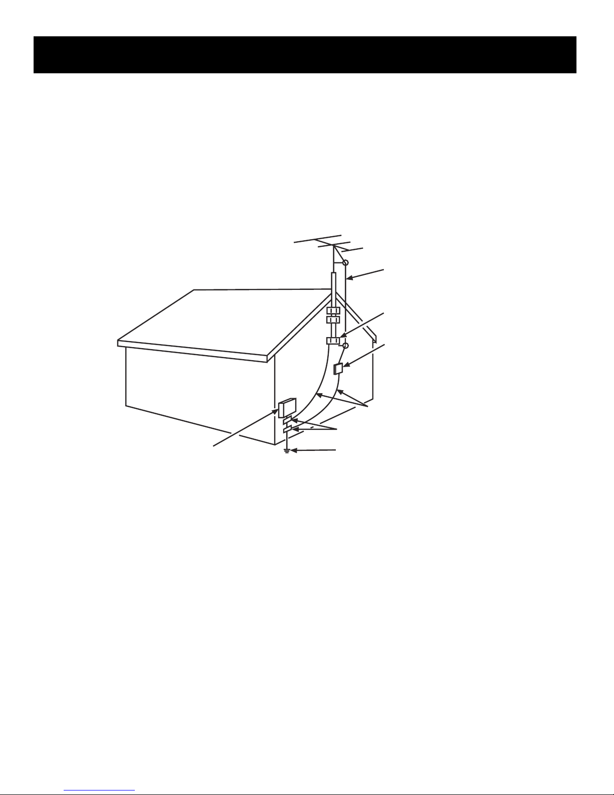
25. If an outside antenna or cable system is connected to the TV, be sure the antenna or cable system is grounded to provide
some protection against voltage surges and built-up static charges. Section 810 of the National Electrical Code,
ANSI/NFPA NO.70, provides information with respect to proper grounding of the mast and supporting structure,
grounding of the lead-in wire to an antenna discharge unit, size of grounding conductors, location of antenna discharge
unit, connection to grounding electrodes, and requirements for the grounding electrodes. (See Diagram Figure A.)
24. To reduce the risk of electric shock, the grounding of center pin of plug must be maintained.
Safety Precautions
iii
ANT E N NA
LEA D
IN
WIRE
GRO U N D
CL A M P
GRO U N DING C OND U C TORS
(NE C
SE C T ION 8 1 0-2 1 )
GRO U N D
CL A M PS
POW E R SE R V ICE G R OUN D I
NG
ELE C T ROD E
SY S T EM
(NE C
AR T 250, P ART H)
ELE C T RIC S E RVI C
E
EQU I P ME
N T
ANT E N N
A
DIS C H ARG E UNI
T
(NE C
SE C T ION 8 1 0-2 0 )
Diagram Figure A
23. WARNING: To prevent injury, this apparatus must be securely attached to the floor/wall in accordance with the
installation instructions.
26. CAUTION: This device employs a laser system. Use of controls, adjustments or the performance of procedures other than
those specified may result in hazardous exposure to radiation. To prevent exposure to laser beam, do not try to open the
enclosure. Do not stare into beam.
Page 5

4
Caution and Warning
....................................................................................................................................
......................................................................................................................................................
.............................................................................................................................................
.........................................................................................................................................
.............................................................................................................................................
.........................................................................................................................................
....................................................................................................................................
.........................................................................................................................
....................................................................................................................................
......................................................................................................................
i
FCC Notice i
Preparation for Your New TV
Check Accessories
6
6
Complete Customer Registration
6
Setup TV Table Stand
6
Select TV Location
6
Connection and Using
6
TV Stand Installation
7
Table of Contents
Safety Precautions ii, iii
........................................................................................................................................................
........................................................................................................................................................
..............................................................................................................................................
......................................................................................................................................................
.................................................................................................................................................
....................................................................................................................................................
.............................................................................................................................................
.........................................................................................................................................
........................................................................................................................................
....................................................................................................................................
........................................................................................................................
.............................................................................................................................................
.....................................................................................................................................
.......................................................................................................................................
......................................................................................................................................
..........................................................................................................................................
..........................................................................................................................................
..................................................................................................................................
..................................................................................................................................
.............................................................................................................................
...................................................................................................................
...............................................................................................................
......................................................................................................................
...............................................................................
.................................................................................
......................................................................................................
......................................................................................................
........................................................................................................................
........................................................................................................................
TV Signal Connection 8
Cable Connections 9
Side Panel Connections
TV Jacks Explanation
Side Keypad and Front Panel
10
10
11
12
13
13
14
15
Connecting AV Composite Video device (Good Video Quality)
Connecting YPbPr Component device (Better Video Quality)
Initial Setup 18
18
18
Menu Language
Signal Type
18
Auto Channel Search
Connecting HDMI device (Best Video Quality)
Connecting a Computer
How to Obtain Various Kinds of Input Sources
Basic Operations 19
19
19
19
19
20
Turning On and Off
Choosing TV Channel
Selecting Input Source
Adjusting TV Stand Angle
Channel Bar
20
20
Adjusting Volume
EPG (Electronic Program Guide)
15
15
Side Panel Buttons
Front Panel
Remote Control Instructions
16
16
16
Inserting Batteries in the Remote
Learning about Remote Control
17
17Remote Control Buttons
Remote Control Reception Angle
Page 6

5
Table of Contents
OSD Menu Operations
.............................................................................................................................
....................................................................................................................................
.........................................................................................................................................
.................................................................................................................................
............................................................................................................
.......................................................................................................................
.......................................................................................................................
....................................................................................................................
...................................................................................................................................................
...................................................................................................................................................
...................................................................................................................................................
.....................................................................................................
.....................................................................................................
.................................................................................................................................................
.................................................................................................................................................
.......................................................................................................................................................
21
21
21
23
24
25
29
31
36
37
39
Adjust the OSD Screen
Picture Menu
Sound Menu
Channel Menu
Parental Menu
Frequently Asked Questions (FAQs)
..........................................................................................................................................
32
DVD Operations
Troubleshooting
V-Chip Rating Explanations
Universal Remote Control Code List
Wall Mounting Unit Specification
39
39
40
40
41
.................................................................................................................................
Product Specification
42
US V-Chip Rating System
Canadian English Rating System
Canadian French Rating System
Setup Menu
Others Menu
Page 7
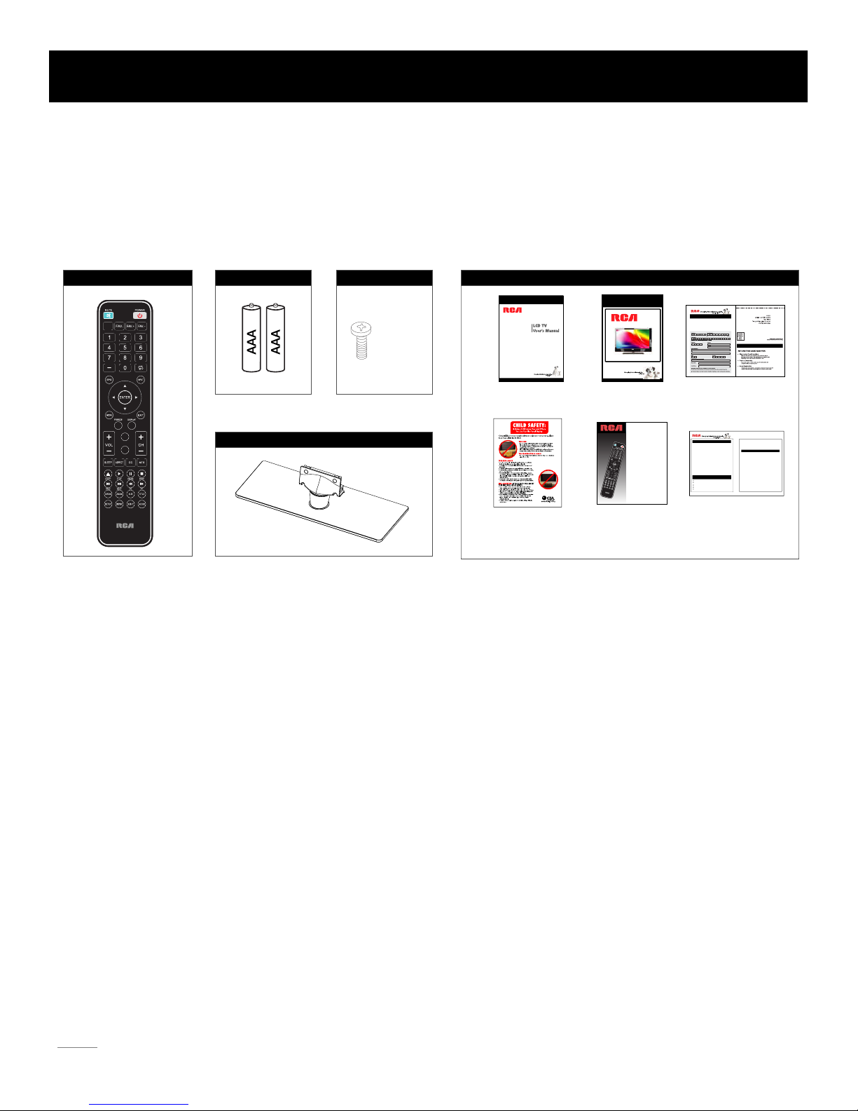
Note: Above accessories are subject to change without notice.
Before Turning On TV
Check Accessories
Check the accessories that are packed with your TV.
Select TV Location
Select a flat, stable table to locate your TV set. Please follow the Safety Instructions when locating the TV.
Setup TV Table Stand
Please refer to TV Stand Installation guide in next page to carry out stand installing.
Complete Customer Registration
Please fill the RCA registration Card and return it to the address printed on it. That is for your customer service. To achieve best
customer warranty work, please read and fill it carefully.
Connection and Using
After placing your TV properly, you can connect the TV with power supply and cable components. For further information, see page
10 to page 13.
USER’S GUIDE
REGISTRATION
CARD
WARRANTY
CARD
QUICK START
GUIDE
REMOTE CONTROL
GUIDE
CHILD SAFETY
CARD
PART NO.: RE20QP28
REMOTE CONTROL
TAPPING
SCREW
TV STAND SCREWS
TV STAND
DOCUMENTS
Preparation for Your New TV
6
AAA BATTERIES
CH LIST
.
PICTURE
SOUND
Quick Start Guide
Part No.:RN4132E010
Part No.: RN0326E0100
Model Number.
26LA30RQD
32LA30RQD
Limited Warranty for USA
Coverage– Labor
For a period of 12 months from date of purchase of your RCA product, we will pay an
au
thorized RCA service center the labor charge to repair any defects in materials or
workmanship in your television. If your television is unrepairable we will provide you with
a refurbished unit of the same or better model.
Coverage – Parts
For a period of 12 months from date of purchase of your RCA product, we will pay an
author
ized RCA service center for the new, or at our option, refurbished replacement parts
nee
ded to repair any defects in material or workmanship in your television. If your television is
unrepairable we will provide you with a refurbished unit of the same or better model.
Coverage – LCD Panel
For a period of 12 months from date of purchase of your RCA product, we will pay an
author
ized RCA service center for the new, or at our option, refurbished LCD panel needed to
re
pair any defects in material or workmanship in your television. If your television is unrepairable
we will provide you with a refurbished unit of the same or better model.
How to Obtain Service
Call our customer service representative toll free at 1-888-977-6722 and provide your model number,
ser
ial number and date of purchase. Or visit at www.rca.com
The
service representative will review your options for service. As a convenience we offer three ways
to obtain warranty service. You may mail your product to the address provided by the service
re
presentative, you may take your product to an authorized service center, or you may request in
ho
me
service (servicer will determine if product is serviceable in home or must be taken back to local
service center for repair). Service representative will supply instructions for preferred service. At the
time
of service proof of purchase such as original receipt, will be required. Only 37” LCD size and
ab
ove are applicable for in-home-service.
Items Not Covered By Limited Warranty
Your limited warranty does not cover the following items:
Un-installation, installation and adjustment of customer controls and operating instruction.
Batteries and customer replacement fuses.
Damage due to misuse, abuse, negligence or neglect including but, not limited to, damage
resulting
from exposure to moisture, humidity or salt.
Inability to receive a signal due to problems not caused by the product.
Damage to the product due to images burnt into the screen.
Product purchased or serviced outside the United States / Puerto Rico.
Product modified or incorporated into other products.
Damage due to acts of nature, including but not limited to, lightning damage or flooding.
Service calls which do not involve any defect in materials or workmanship.
Commercial Use Excluded
This limited warranty only applies to products used for personal or use and does not cover any
pro
duct used for institutional, commercial or rental purposes.
LIMITATION OF WARRANTY
THIS LIMITED WARRANTY IS THE SOLE AND EXCLUSIVE WARRANTY APPLICABLE TO THIS
LAR
PURPOSE). NO VERBAL OR WRITTEN
PRO
DUCT. ON CORP US, INC., THE MANUFACTURER OF THIS PRODUCT, DISCLAIMS ALL
OTHER WARRANTIES, LUDING ALL IMPLIED WARRANTIES EXPRESSED OR IMPLIED (INC
OF MERCHANTABILITY
OR FITNESS FOR A PARTICU
INF
ORMATION GIVEN BY ON CORP US, INC., ITS AGENTS, INDEPENDENT
CONTRACTORS
, SALES REPRESENTATIVES, EMPLOYEES, RETAIL DEALERS, WHOLESALE
DISTRIBUTOR
S OR
ANY OTHER THIRD PARTY SHALL CREAT E A GUARANTY OR
INCREASE
. EXPAND OR MODIFY THE SCOPE OF THIS LIMITED WARRANTY.
THIS
LIMITED WARRANTY PROVIDES THE SOLE AND EXCLUSIVE REMEDY FOR THE
CONSUM
ER OF REPAIR OR REPLACEMENT OF THE PRODUCT. ON CORP US, INC. SHALL
NOT
BE LIABLE FOR SPECIAL, INCIDENTAL OR
THE
USE OF THE PRODUCT OR ARISING OUT OF A BREACH EXPRESSED OR IMPLIED
CONSEQU
ENTIAL DAMAGES ARISING OUT OF
WARRANTY ON THIS PRODUCT.
THIS
LIMITED WARRANTY AND THE DISCLAIMERS CONTAINED HEREIN ARE GOVERNED BY
THE LAWS OF THE STATE OF INDIANA. EXCEPT TO THE EXTENT PROHIBITED BY
APPLICABLE
LAW, ANY IMPLIED WARRANTY OF MERCHANTABILITY OR FITNESS FOR A
PARTICUL
AR PURPOSE IS LIMITED TO APPLICABLE LIMITED WARRANTY PERIOD(S) SET
FORTH ABOVE.
THIS
WARRANTY GIVES YOU SPECIFIC LEGAL RIGHTS AND YOU ALSO MAY HAVE OTHER
RIGHTS
THAT VARY FROM STATE TO STATE.
Product Registration Card
A product registration card was included with your product. Completion of the card is not a condition
of warranty coverage.
RCA is a trademark of RCA Trademark Management SAS and used under license by ON Corporation
xe(. 100003C-06S03CL73-C2319 )
PRODUCT REGISTRATION
Warranty Card
Thank you for choosing a RCA product!
Please register your product online at
www.rca.com/television
Or fill out and mail this card to register your purchase,
The information on the card enables us to serve you better with products and promotions
developed to meet your needs and interests.
Please take a moment right now to fill it out.
Remote Control Guide
Program Your Universal Cable
or Satellite Remote Cont
rol to
Operate
Your New RCA TV!
If you would like to program your other
household remote controls to your new RCA
television, please consult the User
’s Manual
supplied by your Cable or Satellite provide
r.
The Cable or Satellite providers’ User
’s Manuals
should include instructions on how to program
their remote to your television.
Below is a list of RCA codes for the most
common Cable and Satellite providers.
Use the RCA code that is associated with your
Cable or Satellite provider (if applicable).
DIRECTV..........................0178,10178
Time
Warner Cable...........0178,10178
Comcast..................................1017
8
Cox
Communications..................0178
Dish
Network.............................627
Fios
Verizon.....0205,0057,0493,0775
If the RCA code associated with your Cable or Satellite
provider is not listed above, if the code above does
not work, or if you can not locate the instructions for
programming your household
remote to your television, call your local Cable or
Satellite provider
’s customer service center.
C
H
S
I
L
T
.
E
R
U
T
C
I
P
D
N
U
O
S
Page 8
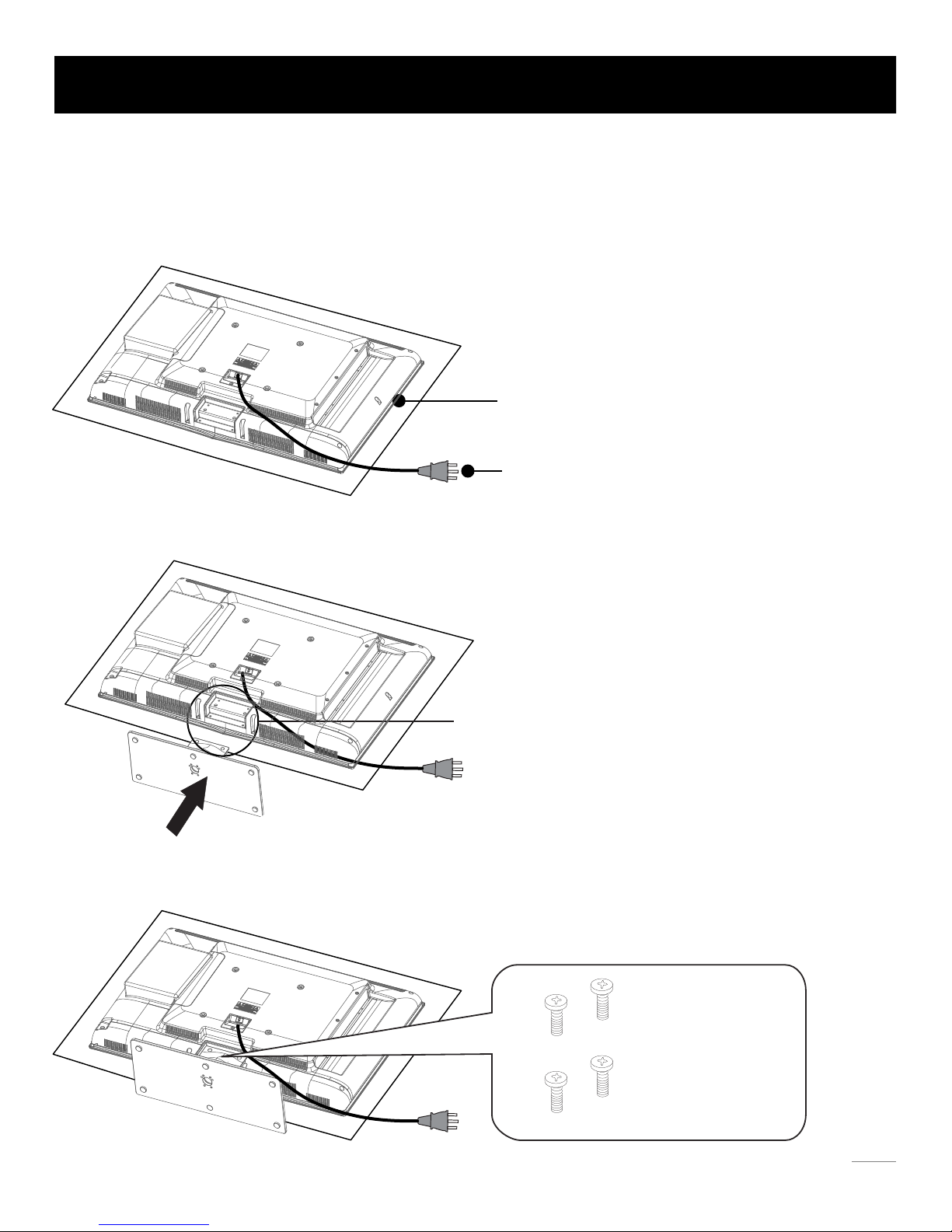
TV 26LA30RQD/32LA30RQD are packaged with the TV stand separated from the cabinet. To setup the TV table stand,
please carry out the
installation according to the instructions below.
The LCD panel is easy to scratch, so please:
1. Choose an absolutely flat surface to place the TV on.
2. Use soft cloth or cushion to face the TV panel.
Do not put TV on the table directly.
Always unplug the AC cord first when installing/removing
the stand.
Align the four holes in TV stand body to the screwholes in TV
stand base.
Step One
Place the TV faced down on a soft cloth or cushion to prevent the
LCD panel from being damaged.
Step Three
Insert the four M4 tapping screws (which are totally the same) and
tighten them.
Step Two
Put the stand body (plastic) onto the stand base in cabinet.
TV Stand Installation
7
Four black
stand screws
Page 9
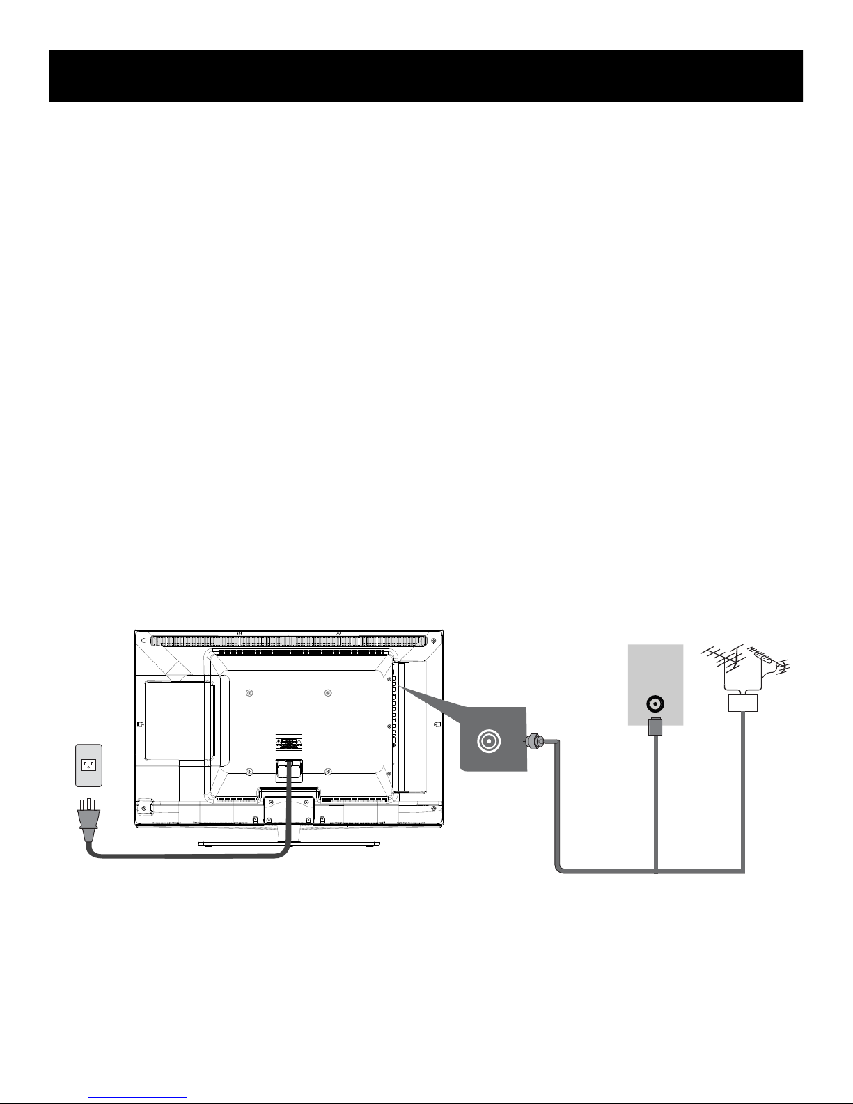
The first step in connecting your TV is obtaining the signal. Your TV 26LA30RQD/32LA30RQD has a side panel, which allows you to
receive analog and/or digital television channels via ANT/CABLE jack.
Befo
re connecting your TV, determine using an antenna or a cable service to obtain the signal.
A. Antenna
Connect the antenna to TV via coaxial cable on ANT/CABLE jack of the side panel. You are ready to receive air local digital and
analog channels.
B. Cable TV service
Connect the cable TV wall jack to TV via coaxial cable on ANT/CABLE jack of the side panel. You are ready to receive off-air local
digital and analog channels.
C. Set-Top Box
If you use a set-top box, you may need to call your cable company or satellite service provider, which use a special connection,
please refer to the user’s guide of set-top box.
Note: Do not plug the AC cord until you have accomplished all the connections.
AC Power Cord
(Connect after all the other connections are done.)
AC
110V/60Hz
AntennaCable TV
Or
TV Signal Connection
8
WALL
OUTLET
ANT/
CABLE
Page 10
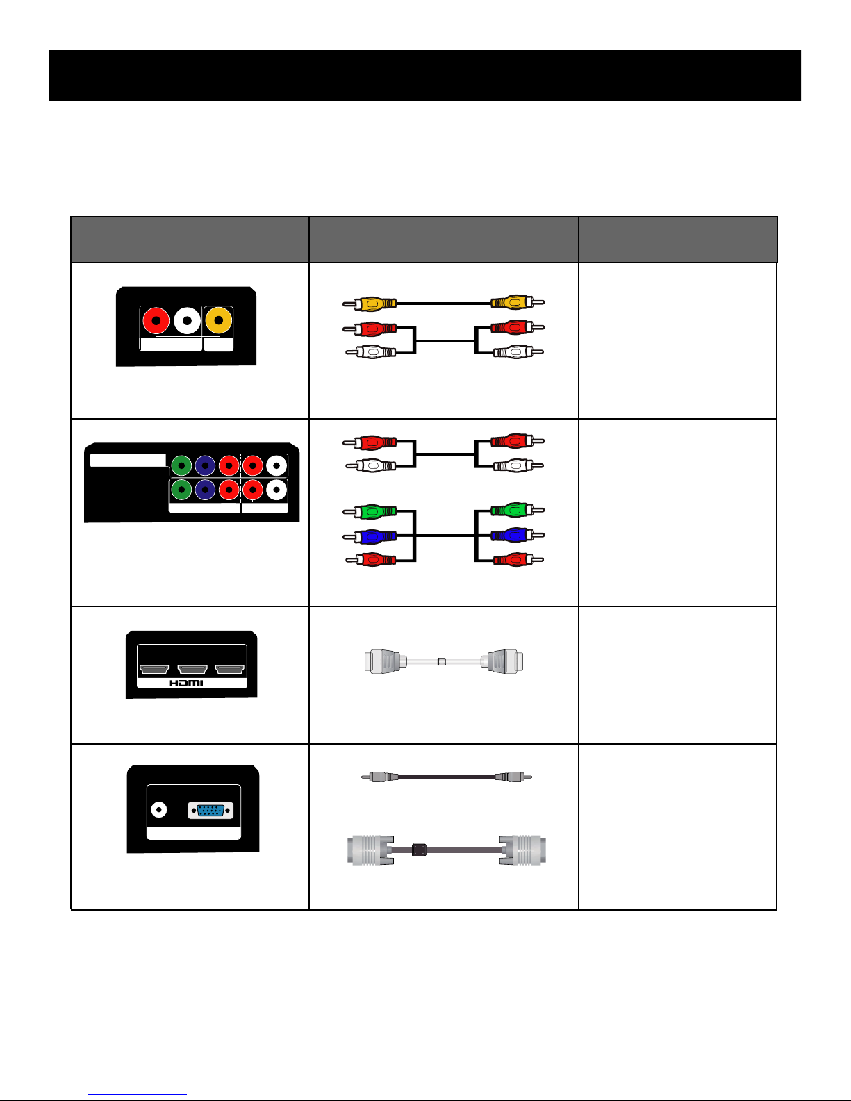
Choose Your Connections
TV 26LA30RQD/32LA30RQD supports various of connecting ways from other devices (such as DVD, VCR, Set-top box, ect.).
Please follow the table sheet to choose the cables which adapt to your device.
HDMI cable
TM
Note:
HDMI, the HDMI logo, and High-Definition Multimedia Interface are trademarks or registered trademarks of HDMI Licensing LLC
Caution:
Unplug the AC cord when you connect other devices to TV.
Cable Connections
Jacks Cables Further Information
AUDIO-IN L and R, Video In
AUDIO-IN L and R
COMPONENT 1 Y, Pb, Pr
COMPONENT 2 Y, Pb, Pr
HDMI IN 1, 2, 3
PC INPUT
VGA, Audio In
Audio Cable
Audio cable with 3.5mm terminal
VGA cable
COMPONENT video cable
Video/Audio cable
Go to page 10
Go to page 11
Go to page 12
Go to page 13
9
R L
AUDIO-IN
Video
In
Y Pb Pr
R
R L
L
Y
Pb
Pr
COMPONENT 1 AUDIO-IN
COMPONENT 2
1
2 3
NI
VGA
Audio-In
PC INPUT
Page 11
R L
AUDIO-IN
Video
In
Audio
L R
Audio
L R YPbPr
Video
HDMI
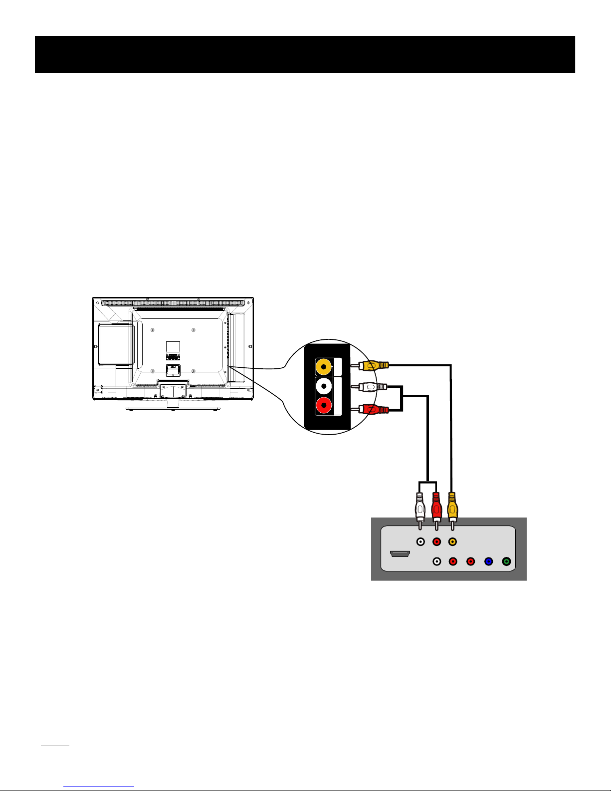
Side Panel Connections
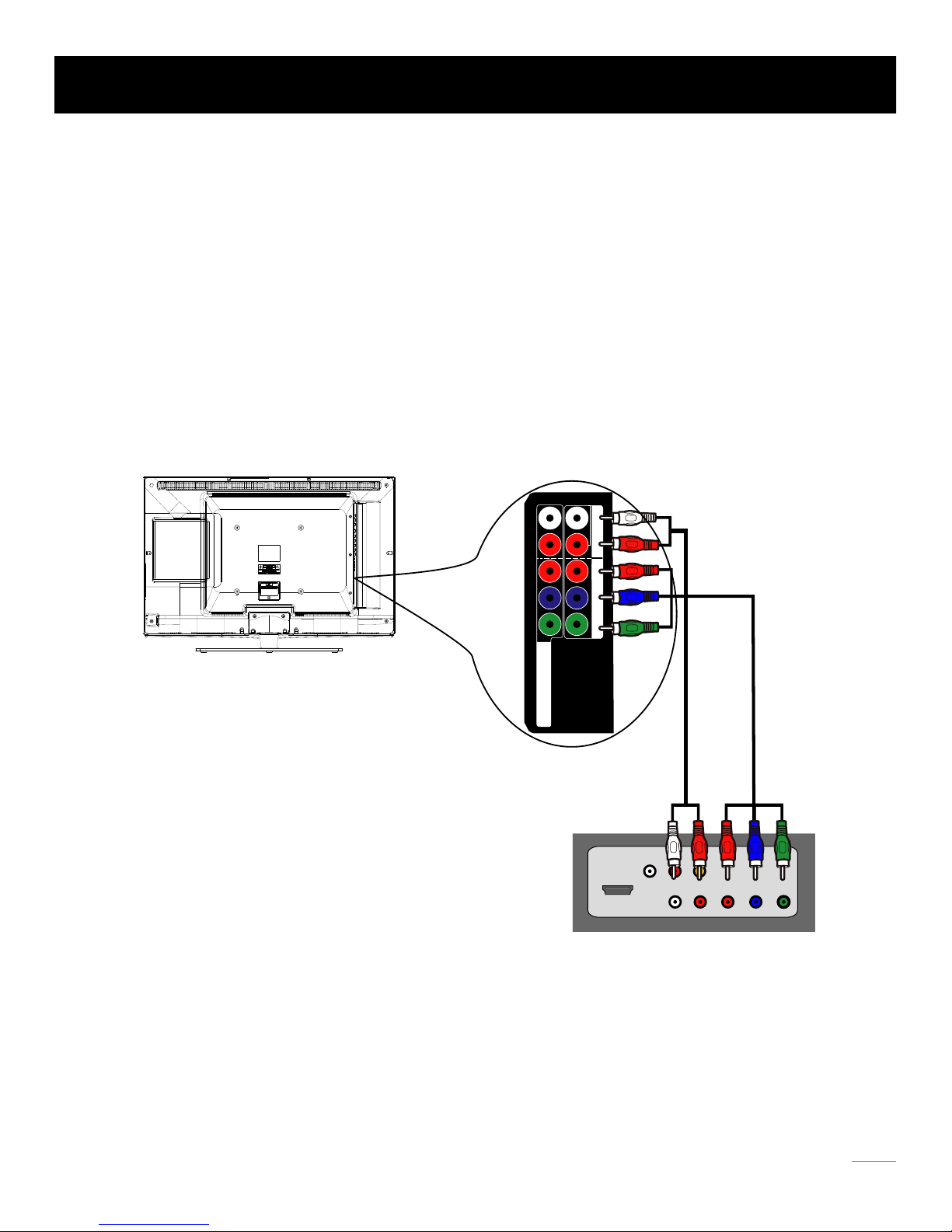
Connecting AV Composite device (Good Video Quality)
To connect an composite AV device, such as a DVD player, follow these steps:
1. Connect the Video In jack on the side of TV to the video output jacks of device via video cable (yellow).
2. Connect the AUDIO-IN L and R jacks on the side of TV to the audio output jacks of device via audio cable.
Notice the left channel jack and plugs are white and the right channel jack and plugs are red.
Composite Video Connection
The picture below is an example of a connection using the composite video jack.
Note: AV signal belongs to composite video. This kind of video signal has regular good display quality.
10
The output panel of other device
The back of TV
Page 12
Y Pb Pr
R
R L
L
Y
Pb
Pr
COMPONENT 1 AUDIO-IN
COMPONENT 2
Audio
L R
Audio
L R YPbPr
Video
HDMI
The output panel of other device
Side Panel Connections
Connecting YPbPr Component device (Better Video Quality)
To connect a component device, such as a DVD player, follow these steps:
1. Connect the COMPONENT 1,2 Y/Pb/Pr jack on the side of TV to the video output jacks of device via video cable (green,
blue and red).
2. Connect the COMPONENT 1,2 AUDIO-IN L and R jacks on the side of TV to the audio output jacks of device via audio cable.
Notice the left channel jack and plugs are white and the right channel jack and plugs are red.
Component Video Connection
The picture below is an example of a connection using the component video jack.
Note: Y/Pb/Pr jacks are component video. This kind of video signal has better display quality.
11
The back of TV
Page 13
1
2 3
NI
Audio
L R
Audio
L R YPbPr
Video
HDMI
The output panel of other device
Side Panel Connections
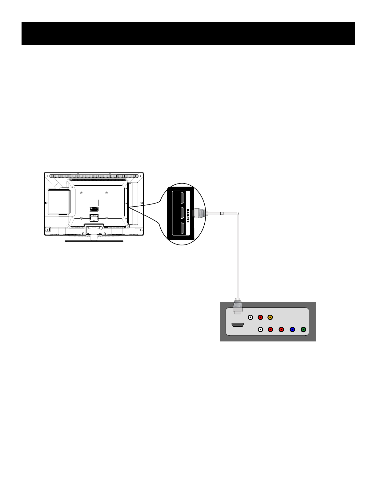
Connecting HDMI device (Best Video Quality)
To connect an HDMI device, such as a DVD player, please Connect the HDMI1, 2, or 3 jack on the side of TV to the output
jacks of device via HDMI cable.
HDMI Connection
The picture below is an example of a connection using the HDMI video jack.
Note: HDMI (High-Definition Multimedia Interface) is a compact audio/video interface for transmitting uncompressed digital
data. It carries the audio and video signal via the same cable and has the best display quality.
12
The back of TV
Page 14
VGA
Audio-In
PC INPUT
VGA
Speaker or
headphone
Side Panel Connections
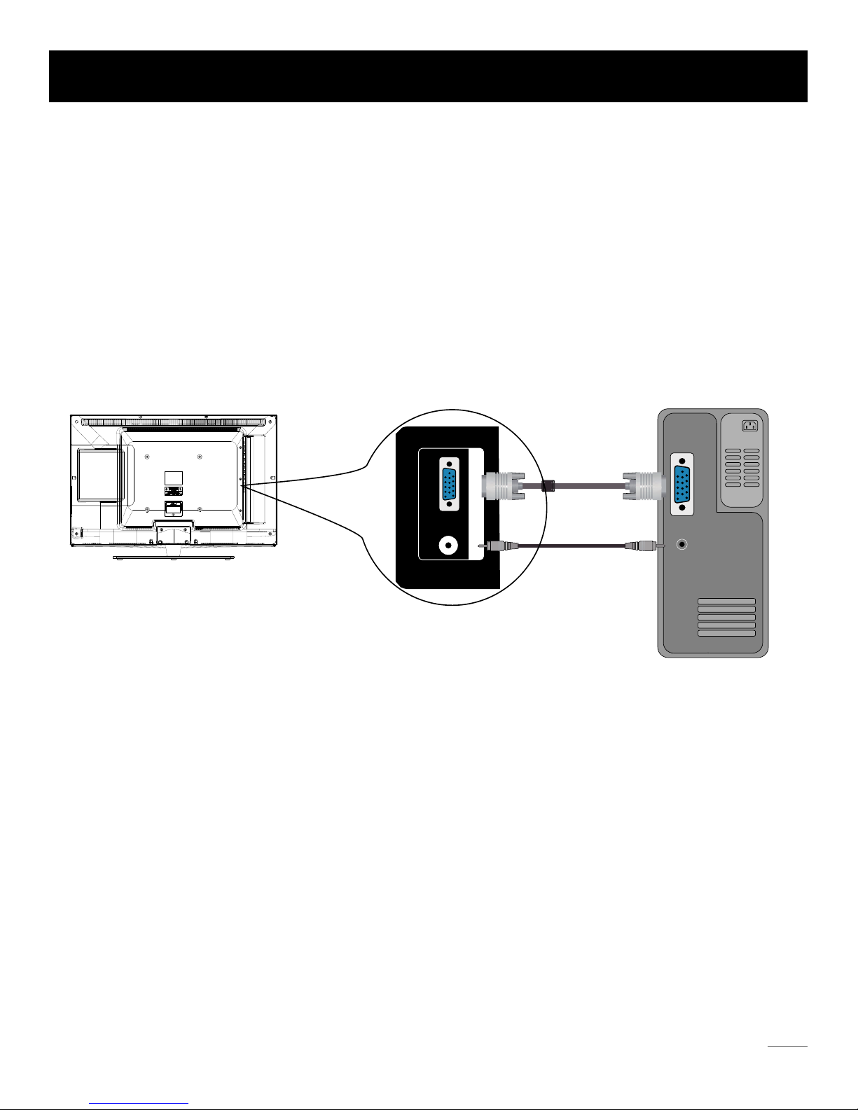
Connecting a computer
To connect a computer, follow these steps:
1. Connect the PC INPUT VGA port on the side of TV to the VGA output jack of device via D-sub 15-pin cable.
2. Connect the PC INPUT Audio In jack on the side of TV to the audio output jack of computer with audio cable (3.5mm).
PC Connection
The picture below is an example of a connection using your TV as a PC monitor.
How to Obtain Various Kinds of Input Sources
After connection is done, press INPUT button on remote control or TV top panel to choose the input source you need.
See page 19, Basic Operation of TV.
Note: If you want to use your TV as a monitor, please notice that the maxium resolution for 26LA30RQD/30LA30RQD is
1366*768. Please set the computer graghic correctly.
13
PC
The back of TV
Page 15

TV Jacks Explanation
ANT/CABLE: Connect to receive the signal from your antenna or cable via coaxial cable.
Head phone:
Connect a 3.5mm headphone for personal audio.
Digital Audio-out:
Connect a coaxial cable for digital audio output.
AUDIO OUTPUT L/R:
Connect double-channel coaxial cables for analog audio output.
AUDIO-IN L/R, Video In: Connect an AV device that has composite video jacks, such as a VCR
• AUDIO-IN L: Left audio channel connection. The left audio connector is usually white. For mono audio
sources, be sure to use the left AUDIO INPUT.
• AUDIO-IN R: Right audio channel connection. The right audio connector is usually red.
COMPONENT 1,2 Y/Pb/Pr:
Connect a device that has component video jacks, such as a DVD player.
• Y/Pb/Pr (Component Video): They provide good picture
quality because the video signal is separated into three components.
Use three video-grade or component video cables for the connection. When using Y/Pb/Pr, make sure you connect left and
right audio cables to the Audio L and Audio R jacks.
HDMI1, 2, 3: (High-Definition Multimedia Interface) It provides an uncompressed digital connection that carries both video and audio
data by way of an integrated mini-plug cable.
PC INPUT VGA: Connect your computer or other device with a VGA output to this jack using a 15-pin, D-sub cable.
PC INPUT Audio-In: Use to obtain sound when a PC is connected to TV. Use 3.5mm stereo mini-pin cable to connect PC to TV.
SERVICE: For service use only. Do not connect any device.
or a DVD player. To access device connected to these jacks, press the INPUT button on your
remote; then press the up/down arrow to select AV. Press the ENTER button at last to confirm.
To access device connected to the Y/Pb/Pr jack, press the INPUT button on your remote; then press the up/down arrow to
select Component1 or Component2. Press the ENTER button at last to confirm.
Note:
•
The AV input (Video In), COMPONENT 1 input (Y, Pb, Pr) share the same audio input jacks-AUDIO-IN L/R.
Note:•
Digital Audio-out and AUDIO OUTPUT L/R are supposed to be connected to audio power
amplifer, which provides smoother and more powerful sound performance.
14
1
2 3
VGA
ANT/
CABLE
HEAD
PHONE
Y Pb Pr
R
R
L
R L
L
Audio-In
SERVICE
Y Pb
Pr
PC INPUT
NI
COMPONENT 1 AUDIO-IN
Digital
Audio-out
Video
In
AUDIO
OUTPUT
COMPONENT 2
Page 16

Side Keypad and Front Panel
Side Keypad Buttons
Front Panel
If you cannot locate your remote, you can use the side keypad buttons on your TV to operate many TV features.
INPUT:
MENU ( ): Displays the TV Main Menu.
Displays the Source Select List.
VOL-: Decreases the volume. In the TV menu system, it acts like the left arrow on the remote control and can be used
to select menu options.
VOL+: Increases the volume. In the TV menu system, it acts like the right arrow on the remote control and can be used
to select menu options.
CH-: Scans down through the channel list. In the TV menu system, it acts like the down arrow on the remote control
and can be used to select menu options.
CH+: Scans up through the channel list. In the TV menu system, it acts like the up arrow on the remote control and
can be used to select menu options.
POWER ( ): Turns the TV on and off.
About remote control working distance and angle, see page 16.
Power/Standby Indicator: Blue and red dual-color LED. It shows red when the TV is turned off and blue when turned on.
Remote Control Sensor: Remote control IR sensor, which receives infrared ray sent by remote control.
Remote Control Sensor
Power/Standby Indicator
(blue/red)
15
Page 17

Inserting Batteries in the Remote
Remote Control Reception Angle
• Remove the cover of battery cabin on the back of the remote control by lifting the cover.
• Insert two AAA batteries, making sure the polarities (+ and -) are aligned correctly.
• Place the cover back.
• Are the polarities (+, -) correct?
• Are the batteries worn out?
• Is there an AC power failure?
• Is the power cord plugged in?
• Is there any interference or block near the remote
control sensor?
Use your remote control within the distance and angle range shown below.
If the remote control does not work, check these points:
• Used batteries should be recycled.
• Keep out of children’s reach.
• DO NOT use new and old batteries together.
• Change both the batteries at the same time.
• When not using the remote control for a long time,
remove the batteries from the unit.
CAUTION:
7 meters
Remote Control Instructions
16
Page 18

Remote control part number RE20QP28
Remote Control Buttons
Numeric Buttons: Use these buttons to enter numbers.
CH.LIST: Displays the channel list.
To enter a digital channel with a sub-channel, enter the main channel; then, press this
button to enter the sub-channel and press ENTER.
PICTURE: Switches between the preset picture mode (see page 21).
SOUND: Switches between the preset sound mode (see page 23).
ENTER: Enter and confirm button.
EPG:
Shows Electronic Program Guide (see page 20).
INPUT: Accesses the available input channels (TV, AV, Component 1/2, HDMI 1/2/3, PC).
Use the arrows to highlight options, and press ENTER to select.
MENU: Accesses the Main Menu, or return to the upper level of a sub-menu.
EXIT: Exits the current menu or function.
“ ”:
ASPECT: Switches between the preset screen size mode (see page 22).
DISPLAY:
Displays the Channel Bar (see page 20).
CC:
Selects the closed caption.
MTS:
Selects the multi-channel television sound.
Freeze the current screen frame, press again to return to normal.FREEZE :
Scans up or down through the current favorite channel list.
FAV.: Adds the current channel to your favorite list, or erases the current channel from
FAV.+ or FAV.- :
your favorite list (if this channel is a favorite channel already).
SLEEP:
Selects the sleep timer, after which the TV will shut off automatically.
EJECT ( ): Ejects or loads the disk from DVD module.
PAUSE ( ): Pauses the DVD playing.
STOP ( ):
Stops the DVD playing.
PREV ( ): Goes back to the previous chapter of DVD.
PLAY ( ):
Plays the DVD disk.
NEXT ( ): Skips to the next chapter of DVD.
FR ( ) or FF ( ): Fast review or fast forward.
DVD-M: Returns to DVD root menu.
ZOOM: Zooms the size of screen.
TITLE: Returns to DVD title menu.
SETUP:
Displays the DVD-setup menu.
REPEAT: Selects the repeating mode.
SUB-T: Selects the DVD subtitle.
AUDIO: Selects the DVD audio language.
Note: For DVD control and operation details, see page 32 to page 35.
A-B:
Sets the A-point to B-point repeating.
CH+ or CH-: Scans up or down through the current channel list. Press once to change
the channel up or down; press and hold to continue changing channels.
VOL+ or VOL-: Increases or decreases the TV volume.
POWER ( ): Turns the TV on or off.
Arrows ( / / / ): Uses the four arrows to highlight different items in the TV menu or
change the value. The up/down arrow can also work as CH+/CH-
button, and the left/right arrow can also work as VOL-/VOL+ button.
Recall ( ):
Returns to the previous channel.
MUTE ( ): Reduces the TV volume to its minimum level. Press again to restore the volume.
Learning about Remote Control
17
CH LIS T
.
PICTURE
SOUND
Page 19

If it is the first time you turn on your TV, or you have done Clear Channel List option (see page 28), the initial setup menu appears
automatically.
Menu Language
To choose your menu language, press the left/right arrow until the language you need appears.
Available languages: English, French and Spanish.
To choose your TV tuner signal type, press the left/right arrow until Air or Cable appears.
Note: please select TV signal type according to the antenna or cable closed circuit TV you use.
Signal Type
To execute auto channel search, press the up/down arrow to highlight Auto Channel Search and press ENTER button.
What to notice:
1. The channel search access starts from the Analog TV channel searching and ends at Digital TV channel searching.
2. The channels that have been found will be stored automatically.
Auto Channel Search
Initial Setup
:Sele ct Menu:Retu rn
:Chan ge Setti ng
Menu Lan guage Engli sh
Air
Execu te
Signa l T ype
Auto Cha nnel Sea rch
MENU
Initial Setup
18
AUTO CHANNEL SEARCH - A ir
Analo g Cha nnels Foun d: 1
Digit al Ch annel s Fou nd: 0
3%
Return
Now Searching... Please Wait...
:Stop Auto C hanne l Sea rch
MENU
3. You can press MENU or EXIT button to skip analog/digital channel searching.
4. You can press MENU or EXIT repeatedly to end the channel searching.
Page 20

Tuning To Analog Channels
An analog channel has a channel number beginning with “A”. Input the digital number with numeric buttons directly and press
ENTER button to confirm.
For example, to watch analog channel “A51”, press “5”, “1”, “ENTER” on remote control in sequence.
Adjusting TV Stand Angle
The TV cabinet can manually adjust to left or right for 30 degrees from the centre.
You can adjust the angle for the best viewing effect and comfort.
Tuning To Digital Channels
Note: Although there is no analog TV signal available in America, we reserve ATV functions for some expansible use.
A digital channel has a channel number beginning with “D”. Input the main digital number with numeric buttons directly, then press
“ ” button on remote control, and input the sub number at last.
For example, to watch analog channel “D31-1”, press “3”, “1”, “ ” button. “ENTER” on remote control in sequence.
You can use CH+ button to increase channel number and CH- to decrease channel number. When no OSD (On Screen Display) is
used, the up/down arrows can also work as CH+/CH- buttons.
Press INPUT button on remote control to display Source Select list.
Use up/down arrows to highlight the source you need and press ENTER to confirm.
Changing Channels Directly
Basic Operations
Turning On and Off
Choosing TV Channel
Selecting Input Source
Connect the AC cord to power the LCD TV. At this time the TV will enter standby mode and power indicator shows red.
Use Power button ( ) on the top panel of TV or on the remote control to turn on the TV. After switching off the TV for 5 seconds,
you can turn on TV again.
Source Select
TV
AV
Component 2
Component 1
HDMI 1
HDMI 2
HDMI 3
PC
DVD
19
Page 21

Channel Bar
Press the DISPLAY button on the remote control, the channel bar will appear on the right top of screen. It displays the current
channel’s information
. The following list describes the items on the channel bar.
Adjusting Volume
Press the VOL+/VOL- button on the remote control to adjust the volume. If you want to switch sound off, press MUTE ( ).
EPG (Electronic Program Guide)
Press EPG button on the remote control, the electronic program guide will appear in the center of screen.
The electronic program guide gives the TV program playing project. You can use left/right arrows to switch pages.
When OSD (On Screen Display) is not used, the arrows left/right can also work as VOL-/VOL+ butttons
.
A2/D50-1
MTV/KOCE-HD
ATV DTV
If the channel is analog, A is displayed. If it’s a digital channel, D is displayed. For example, in the pictures
above, A2 is an analog channel, and D50-1 is a digital channel ( -1 is a sub-channel number)
.
Displays the channel label
.
Mo
no/English Displays whether the current channel is being broadcast in stereo or mono. If the current channel is digital,
this space will be SAP (Second Audio Program) language
.
480i/1080
i Displays the signal resolution.
16:9/CC/TV-PG Displays the screen aspect ratio, closed caption and TV rating level of the current program or channel
.
And these are only available for digital channels.
Oct-31 23:14 Mon Current date and time
.
Mono
A2
480i
Oct-31 23.14 Mo
n
A2
English
KOCE-
HDMTV
D50 - 1
1080i
Oct-31 23:14 M
on
Basic Operations
D50 - 1
KOCE-HD
Smart Travels - Pacific Rim with Rudy Maxa
23 : 00 - 23 : 30
Stockholm & Sweden is a natural-born beaut
y, winning us over with
luxuriant landscapes and sleek Scandinavian style.
We cruise through Stockholm’s
sun-dappled archipelago, visit a designer hotel and sip cocktails in the trendy Ice Bar
(a lounge...
:Page
:Retur n
MEN U
20
Page 22

Adjust the OSD Screen
The OSD (On Screen Display) menu enables you to approach to the TV functions.
To use OSD menu system, press MENU button on remote control, then use left/right arrow to highlight an option from PICTURE,
SOUND, CHANNEL, PARENTAL, SETUP or OTHERS and press ENTER button.
Press the up and down arrow to move to a different option within each menu. If necessary, press ENTER or right arrow to display
the choices of the option you’ve highlighted. If available, use the text at the bottom of each screen for help. To return to the
previous menu, press the MENU button.
To exit the OSD menu:
• Press the EXIT button. The menu will clear from the screen.
• Press the MENU button repeatedly until the menus disappear.
Allows you to select one of the preset picture settings:
SOUND CH ANN EL PA RENTA L SET UP O THERS
Picture Menu
Picture Settings
The Picture Menu contains menus and controls to configure the way the picture appears. The Picture Menu options apply to the
video for the main TV and VIDEO INPUT selections. All picture options can be applied to each input.
Press MENU on the remote. Select Picture from the Main menu. Press the ENTER button to proceed to PICTURE menu.
Picture Settings: Choose the preset visual mode of your TV:
Use up/down to choose the function you need, press
ENTER or right arrow to adjust or enter a sub-menu. The
sub-menu image and explanation are shown below.
Standard, Movie, User, Dynamic. Only in User mode you can
adjust Brightness, Contrast, Color, Tint and Sharpness.
Brightness: Adjust the brightness of picture.
Color: Adjust the richness of color.
Tint: Adjust the balance between red and green level (only
available in NTSC signal.
Sharpness: Adjust the sharpness level of picture.
PICTU RE
:Se lect Menu :Go to N ext M enu
/
Scr een S ettin gs
PC Setti ngs
Col or Te mpera ture N orm al
Adv anced Pict ure Set ting s
:Retu rn
MENU
ENTE R
Pic ture Se tting s
:Se lect Menu :C han ge Set tin g
Bri ghtne ss
Con trast
Col or
Tin t
Sha rpnes s
:Retu rn
MENU
Pic ture Mo de Sta ndard
PICTU RE SETTINGS
OSD Menu Operations
21
PICTU RE
Page 23

Screen Settings
PC Settings (only available in PC mode)
Advanced Picture Settings (not available in PC mode)
Color Temperature
Screen Size: Select a screen aspect ratio.
(Available ratio: Full, Normal, Waterglass and Cinema.)
Auto Wide: Make the screen size compliant with signal format
automatically.
If you turn on this function, the Screen Size setting will be ignored.
Please choose the ratio that applies to your video signal format best.
Auto Adjust: Adjust the PC picture display automatically.
This option allows you to select one of th
ree automatic color adjustments: Cool for a bluer palette of picture colors; Normal or
Warm for a redder palette of color.
Horizontal Position: Adjust the horizontal position of picture.
Phase: Adjust the phase of picture.
Reset: Reset all the PC picture settings to factory default.
Vertical Position: Adjust the vertical position of picture.
Clock: Adjust the clock of picture.
Dynamic Contrast: Set dynamic contrast on/off.
Film Mode: Set film mode on/off.
Noise Reduction: Set noise reduction as Off/low/Medium/High.
MPEG Noise Reduction: Set MEPG noise reduction as Off/low/Medium
or High.
Note: Noise reduction helps to reduce the picture “static” or any type of
interference. This featu
re is especially useful for providing a clearer picture
in weak analog signal conditions. The MEPG Noise Reduction specifically
works on video signal with MPEG coding.
:Se lect Menu
:Ch ange Setti ng
Aut o Wid e
:Retu rn
MENU
Scr een S ize Ful l
SCREE N SETTI NG S
:Se lect Menu :P res s t o E xec ute
Hor izont al Po siti on
Ver tical Posi tion
Clo ck
Pha se
:Retu rn
MENU
Aut o Adj ust Exec ute
Res et Exe cute
PC SETTINGS
:Se lect Menu :C han ge Set tin g
/
Fil m Mod e
Noi se Re ducti on
MPE G Noi se Re duct ion
:Retu rn
MENU
ENTE R
Dynamic Contrast Off
Off
Low
Off
ADVAN CE D PIC TU RE SETTINGS
OSD Menu Operations
22
Page 24

Sound Menu
Sound Settings
Surround Mode
The Sound Menu lets you adjust audio output. To access the Sound Menu, press MENU on the remote, and then select SOUND
from the Main Menu. Press ENTER button to proceed to SOUND menu.
Creates a 3D sound surround from standard stereo material, with deep and rich enhancement.
Analog Sound
Select analog TV audio sound type: Stereo, Mono or SAP (only available in TV mode).
Digital Sound
Other Settings
Select digital TV audio language type: English, French or Spanish (only available for DTV channel).
:Se lect Menu :G o t o N ext Me nu
/
Sur round Mode
Ana log S ound Ste reo
Eng lish
Dig ital Sound
Oth er Se tting s
Equ alize r Set ting s
:Retu rn
MENU
ENTE R
Sou nd Se tting s
SOUND
Use up/down to choose the function you need, press
ENTER or right arrow to adjust or enter a sub-menu. The
sub-menu image and explanation are shown below.
:Se lect Menu :C han ge Set tin g
Bas s
Tre ble
Bal ance
:Retu rn
MENU
Sound Mode Sta ndard
SOUND S ETTIN GS
Sound Mode: Choose the preset sound mode of your TV:
Standard, Soft, User, Dynamic. Only in User mode you can
adjust Bass and Treble.
Bass: Adjust the bass component of TV sound.
Treble: Adjust the treble component of TV sound.
Balance: Adjust the balance between the left and right channel.
:Se lect Menu :E nab le/ Dis abl e
Spe aker
:Retu rn
MENU
AVL Off
On
Dig ital Audio Ou tpu t Off
OTHER S ETTIN GS
Set AVL (auto volume control) on/off.
Set TV speakers on/off.
Set the audio output type as Off, PCM or Dolby Digital.
Please set this option according to your power amplifier.
OSD Menu Operations
23
Page 25

Equalizer Settings
Channel Menu
:Se lect Menu
:Ch ange Setti ng
:Retu rn
MENU
Mod e POP
-2 -1 2 3 1 0 -1
100 2 50 1K500 2K 4K 1 0K
EQUAL IZ ER SE TT INGS
The seven-band graphic equalizer allows you to adjust the audio frequency
settings.
You can select one of the equalizer presets (OFF, POP, ROCK,
JAZZ) or c
reate your own personal preset (USER).
Press the left or right arrow to select the frequency (100Hz, 250Hz, 500Hz,
1KHz, 2KHz, 4KHz, 10KHz) you want to adjust. Use the up or down ar
row
to adjust.
The Channel Menu enables you to search, view and edit channels. It is available in TV mode only.
Press MENU and choose CHANNEL from the Main menu. Press the ENTER button to proceed to CHANNEL menu.
Channel List
Display a channel list. It shows the current channels.
Favorite List
Display a favorite channel list. It shows the current favorite channels.
Channel Settings
Go to channel setting sub-menu (as shown below).
CHANN EL
:Se lect Menu
:Go to N ext M enu
/
Fav orite List
Cha nnel Setti ng
Sig nal T ype A ir
Aut o Cha nnel Sear ch
:Retu rn
MENU
ENTE R
Channel List
Exe cute
Use up/down to choose the function you need, press
ENTER or right arrow to adjust or enter a sub-menu. The
sub-menu image and explanation are shown below.
Press left/right arrow to switch the channel you want to edit.
Set if the current channel is contained in channel list.
Enter a channel label to rename the current channel.
CHANN EL SE TTING
:Se lect Menu :S ele ct Cha nne l
In Chann el Li st
Cha nnel Label
Fav orite Chan nel
:Retu rn
MENU
Channel Number 2
Set if the current channel is the favorite channel.
OSD Menu Operations
24
Page 26

Signal Type
Select your TV signal type: Air or Cable.
Auto Channel Search
Execute an auto channel search (see page 18).
OSD Menu Operations
25
• When the Parental Control Menu is accessed from the Main Menu, you need to enter password to unlock the menu function.
• After unlocking, the items in parental control menu can be used. Use arrow up/down to highlight the function you need and
press ENTER or right arrow to use V-chip, Change Password, Front Panel Lock and Source Lock, Clear Channel List sub-menu.
Please enter your four-digit password with numeric keys 0~9.
Note: The original password is “0000”.
V-Chip
Lock Parental Control
The following graphic details where items locate within the V-Chip menu.
US V-Chip
Press ENTER or right arrow to enter US V-Chip ratings menu, which contains two sub-menus: Movie Rating and TV rating.
See next page for more details.
PAREN TAL C ONTRO L
:En ter P asswo rd
V-C hip
Cha nge P asswo rd
Fro nt Pa nel L ock
Sou rce L ock
Cle ar Ch annel Lis t
:Retu rn
MENU
DIGIT AL
Lock Parental Control
V-CHI P
Canada V-Chip
Block Unrated Show
Dow nload able Rati ng
Cle ar Do wnloa dabl e D ata
US V-Chip
:Se lect Menu
:Go to N ext M enu
/
:Retu rn
MENU
ENTE R
Parental Menu
The Setup Menu enables you to lock program with special content, panel key board and input source.
Press MENU and choose PARENTAL from the Main menu. Press the ENTER button to proceed to PARENTAL menu.
Page 27

Movie Rating
TV Rating
Use arrow keys to select the rating level you want to block,
press ENTER to lock/unlock the rating level. If you have
blocked a lower level rating, the higher ratings will be
blocked too.
For example , when PG-13 is blocked, R, NC-17 and X will
be blocked at the same time.
After adjusting, press MENU to return or press EXIT to exit the menu..
TV Rating Overview
Age-Based Ratings
TV-MA Mature Audience Only
TV-14 Parents Strongly Cautioned
TV-PG Parents Guidance Suggested
TV-G General Audience
TV-Y7 Directed to Children 7 Years and Older
TV-Y All Children
D Sexually Explicit Dialogue
L Adult Language
S Sexual Situations
V Violence
FV
For more rating explanation, see page 35.
Fantasy Violence
Content Themes
MOVIE RATI NG
PG
PG-13
R
NC-17
X
G
:Se lect
:Lo ck/Un lock
ENTE R
TV RA TING
TV-Y7
TV-G
TV-PG
TV-14
TV-MA
TV-Y
D
:Se lect :Lo ck/Un lock
ENTE R
L S V FV
Similar with Movie Rating.
OSD Menu Operations
26
Page 28

FRENC H RAT ING
8 ans+
13 ans+
16 ans+
18 ans+
G
:Se lect :Lo ck/ Unl ock
ENTE R
:Re turn
MENU
Canada V-Chip
Press ENTER or right arrow to enter US V-Chip ratings menu, which contains two sub-menus: English Rating and French Rating.
English Rating
Press ENTER or right arrow to enter English rating menu.
French Rating
Press ENTER or right arrow to enter French rating menu.
Block Unrated Show
Block all the unrated program.
Downloadable Rating, Clear Downloadable Data
Activate or downloadable rating data. if available.
ENGLI SH RA TING
C8+
G
PG
14+
18+
C
:Se lect :Lo ck/ Unl ock
ENTE R
:Re turn
MENU
Use arrow keys to select the rating level you want
to block, press ENTER to lock/unlock the rating
level. If you have blocked a lower level rating,
the higher ratings will be blocked too.
For example , when PG is blocked, 14+ and 18+
will be blocked at the same time.
Note: These ratings are
available only if the
broadcaster is sending
rating information.
Similar with English Rating.
OSD Menu Operations
27
Page 29

Front Panel Lock
Select this option to block or unblock the TV’s side panel buttons so that they can’t be used.
Source Lock
This option allows you to lock or unlock the input source. The source blocked can not be
chosen from input list unless you input the correct parental password.
Clear Channel List
This option allows you to execute Clear Channel List function.
This function will reset the whole TV system to factory default (not only reset OSD menu).
Sourc e Loc k
AV
Component 1
Component 2
HDMI 1
:Se lect :On /Of f:Pa ge
ENTE R
:Re turn
MENU
HDMI 2
HDMI 3
TV
Page 1/2
Use up/down arrow
to select the source,
press ENTER to
lock or unlock it.
Change Password
Change the password of parental menu.
Input the old password.
Chang e Pas sword
New PIN
Confirm
:Pa sswor d
DIGIT AL
:Re turn
MENU
Old PIN
Input the new password.
Input the new password again to confirm.
OSD Menu Operations
28
Page 30

OSD Menu Operations
Setup Menu
The Setup Menu lets you config the TV with your preferences.
Select SETUP from the Main Menu. Press ENTER button to proceed to SETUP menu.
Closed Caption
Closed Caption
Press left/right arrow to select closed caption display on or off.
Analog Caption Type
Press left/right arrow to select analog closed caption type: CC1, CC2, CC3, CC4, TEXT1, TEXT2, TEXT3, TEXT4.
Digital Caption Type
Press left/right arrow to select digital closed caption type: Service1, Service2, Service3, Service4, Service5, Service6.
Digital CC Preset
Press left/right arrow to select digital closed caption preset: Default, Custom.
Digital CC Style
Press left/right arrow to go to digital closed caption style sub-menu (see next page).
Only in custom mode you can adjust the digital closed caption style.
SETUP
:Se lect Menu :G o t o N ext Me nu
/
Men u Lan guage Eng lish
Clo ck
:Retu rn
MENU
ENTE R
Closed Caption
Use up/down to choose the function you need, press
ENTER or right arrow to adjust or enter a sub-menu. The
sub-menu image and explanation are shown below.
CLOSE D CAPTI ON
:Se lect Menu :O n/O ff
Ana log C aptio n T ype CC1
Ser vice1
Dig ital Capti on T ype
Def aultDig ital CC Pr eset
Dig ital CC St yle
:Retu rn
MENU
Caption Display
Off
29
Page 31

DIGIT AL CC S TY LE
:Se lect Menu
:Ch ange Setti ng
CC Font Def ault
Def ault
CC Opaci ty
Def ault
Def ault
Tex t Col or
CC Backg round Opa cit y
Def ault
CC Backg round Col or
:Retu rn
MENU
CC Size
Def ault
CLOSE CAPTION
Digital CC Style
Clock
Time Zone
Select your time zone: Eastern, Central, Mountain, Pacific, Alaska, Hawaii, Samoa, Newfoundland, Atlantic.
Auto Clock
Select auto clock on/off. Auto clock helps you synchronize your TV time to standard time (from DTV signal).
Setup Time
Set your TV time manually (needs to turn off auto clock).
Day of Week
Display what day it is (can’t be adjust, display only).
Select the item you want to adjust in Digital CC Style menu
with up/down arrows.
After changing, you can preview the caption style here.
CLOCK
:Se lect Menu :C han ge Set tin g
Aut o Clo ck O N
198 0-01- 06 18 :49 :24Set up Ti me
SunDay of W eek
Time Zone Ea ste rn
OSD Menu Operations
30
Page 32

Others Menu
The Others Menu lets you config the TV with your preferences in other features.
Choose OTHERS from the Main Menu. Press ENTER button to proceed to SETUP menu.
Blue Back
Press ENTER button to select Blue Back on or off. If the Blue Back is turned on, the TV will display a blue background
when there is no signal input.
No Signal Power Off
Press ENTER button to select “No Signal Power Off” on or off. If it is turned on, the TV will shut off after 10-minute
no signal time. We suggest you turn on this function when Blue Back is turned on. Because it may hurt the LCD panel
No Operation Power Off
Press ENTER button to select “No Operation Power Off” on or off. If it is turned on, the TV will shut off after a 3-hours
no operation time.
All Reset
Press ENTER button to execute reset to TV system. All the settings will be reset to factory default.
Audio Only
Press ENTER button to activate audio only mode. The TV will output only sound and the LCD panel will be turned off.
To restore normal playing, hold POWER button for three seconds.
if the blue screen lasts too long.if the blue screen lasts too long.
Note: In PC mode, the monitor standby and power off settings depend on the No Signal Off time.
OTHER S
:Se lect Menu
:On /Off
No Signa l Pow er Off
No Opera tion Powe r O ff
All Rese t
Aud io On ly
:Retu rn
MENU
ENTE R
Blue Back
Exe cute
Use up/down to choose the function you need, press
ENTER or right arrow to adjust or enter a sub-menu.
The sub-menu image and explanation are shown below.
OSD Menu Operations
31
Page 33

TV 26LA30RQD/32LA30RQD has a built-in DVD player module, which you can use to watch DVD disk. The
following operation guide gives the DVD module instruction.
Press INPUT button on remote control, select “DVD” in the Source Select menu (see page 19), then press
ENTER or right arrow to enter DVD mode. The DVD will start playing automatically if there is a disk in DVD
module. If not, the TV will display a standy screen as shown. And a “No Disc” message will appear on screen.
DVD mode of TV 26LA30RQD/32LA30RQD
1. How to enter DVD mode for TV 26LA30RQD/32LA30RQD
Insert the DVD disk with reflector surface facing the front of TV.
Note: The TV will turn to DVD mode automatically when you insert a disk, no matter which mode it is now.
Disk reflector surface facing the front of TV.
Note: Do not insert with much strength.
Insert disk gently and the DVD module will load in the
disk automatically.
2. Insert a disk to DVD player
You can control the DVD playing with keypad on DVD module or with remote control.
For operating information, see next page.
3. DVD control
DVD Operations
32
No Disc
Page 34

DVD Operations
33
Keypad on DVD module
4. DVD basic operations
Play/pause the disk: After inserting the disk to DVD module, the TV will play DVD disk automatically. You can
use PAUSE button to suspend the playing. Press PLAY button, the TV will restore playing.
Stop playing: During playing, you can use STOP button to stop playing. If you press STOP once, the DVD will
be stopped briefly. Press STOP again, it will stop completely and the disk in DVD module no longer wheels.
Eject the disk: You can press EJECT button to eject the disk from DVD module. And press EJECT again, the
DVD will load the disk renewedly.
Going backward or forward: You can press FR for fast review and FF for fast forward. You can also press
PREV to return to the previous chapter, and press NEXT to skip to next chapter.
Function menu: Press DVD-M, you will return to the selection menu of current DVD function. For example, you
are using “Audio Selection”, and you choose “Continue playing”, then after selecting, you can press DVD-M to go
back to “Audio Selection” menu while playing.
Title menu: Press TITLE, you can reset the disk to the title menu. It equals to ejecting and loading the disk again.
Zoom in: Press ZOOM, you can zoom in the screen for 2 times, 3 times or 4 times from centre. This function
provide a better view of the content locate near screen centre.
Subtitle selection: Press SUB-T, you can switch the available subtitles in DVD disk.
Audio language selection: Press AUDIO, you can switch the available audio language in DVD disk.
Repeat: There are two kinds of repeat, one is regular repeat and the other is Atop repeat. For regular repeat,
press REPEAT button to switch between chapter repeat, title repeat and all repeat. For A-to-B repeat, press
A-B once to set the repeating origin and press it twice to set the repeating end.
DVD-setup menu: Press SETUP button, a specific setup menu for DVD will display on screen. This menu is
especially prepared for DVD control. For menu instructions, see next page.
EJECT ( ): Ejects or loads the disk from DVD module.
STOP ( ):
Stops the DVD playing.
PREV ( ): Goes back to the previous chapter of DVD.
PLAY/PAUSE ( ):
Plays or pauses the DVD disk.
NEXT ( ): Skips to the next chapter of DVD.
ZOOM: Zooms the size of screen.
About DVD control buttons on remote control, see page 17, remote
control buttons.
Page 35

5. DVD setup menu
A. General setup page
There exist three sub-menus in DVD setup menu, the first one is General Setup. Press SETUP button on remote
control to display General Setup Page. Press up/down arrow to select the item you want to adjust and press
right arrow or ENTER button to activate it. After activating, use up/down arrow to set item value. When you are
satisfied with the adjustment, press left arrow to return to the upper level of general setup menu. Press left arrow
repeatedly, you can exit the DVD setup menu. To exit setup menu directly, press SETUP.
B. Speaker setup page
Press SETUP button on remote control to display General Setup Page. Press left/right arrow to choose Speaker
Setup Page. The operating method is similar with the General Setup Page.
TV Display
Set the TV display shape.
OSD Lang
Set the DVD OSD language as English, French or Spanish.
Last Memory
Set it on to memorize the last stop point. During playing the DVD, if you change to another mode and then come
back to DVD mode, it can play automatically from the last stop point.
Note: We suggest you turn off the last memory function unless you really need it. To turn on this function may
influence the lifetime of flash memory of DVD module.
DVD Operations
34
TV Display
OSD Lang
Wide
Eng
OffLast Memory
Go To General Setup Page
- - General Setup Page - -
Downmix
Go To Speaker Setup Page
- - Speaker Setup Page - -
Page 36

DVD Operations
35
Downmix
This option is preset as Stereo. That means the DVD player will output a two-channel audio signal (L/R) to
TV front speakers (left/right).
TV Type
Set the TV type as PAL, Auto or NTSC.
Note: American DVD standard is NTSC system, so we suggest you set the TV Type as NTSC. In addition,
you can also set it as PAL to watch some disks with PAL system, or select Auto for convenience.
Audio
Set the DVD audio language.
Subtitle
Set the DVD subtitle language.
Disc Menu
Set the DVD disk menu language.
Default
Reset the DVD setup menu options as factory default.
Parental
Set the parental control rating as KID SAF, G, PG, PG13, PGR, R, NC17 or ADULT.
To change this option, you need password, and the original one is “0000”.
C. Preference page
Press SETUP button on remote control to display General Setup Page. Press left/right arrow to choose
Preference Page. The operating method is similar with the General Setup Page.
TV Type
Audio
NTSC
Eng
Eng
OffSubtitle
Disc Menu
Parental
Password
Default
Go To Preference Page
- - Preference Page - -
Page 37

What’s the most convenient way to view High Definition (HD) video?
Connect an antenna to the TV Input jack to view free local digital channels. You may need to purchase an antenna. (See page 8
for mo
re information about antenna setup).
Visit
www.antennaweb.org for assistance in deciding what type of antenna to use to receive the local digital channels available
to you. After entering your location, this mapping p
rogram tells you which local analog and digital stations are available using a
certain antenna.
Are there other ways to view High Definition (HD) video?
Besides using an antenna as mentioned above, you can also use a set-top box to receive digital video. Contact your cable service
provider or satellite provider to purchase digital programming and have them connect the box to ensure you are viewing channels
in the best way.
How do I tell an analog channel from a digital channel?
Press the DISPLAY button to display the Channel Bar. Look at the top right corner of the screen. An “A” is displayed for an analog
channel. A “D” is displayed for a digital channel.
Note: Since the analog TV in America has been cut off, we reserve analog TV function only for some unexpected use.
Why are there bars on my screen, and can I get rid of them?
Most digital video is sent in a 16/9 format which fills your screen, but is sometimes sent in 4/3 which does not fill your screen. It
depends on how the station or device connected to your TV is formatting the video. If there are bars on the screen, press the
ASPECT button to try a different format that may eliminate the bars. Some bars can't be removed because of the way the format
is sent by the broadcaster. The format changes as you press the ASPECT button and the format type is displayed at the bottom
of the screen. For more information on screen formats, go to page 22.
Why does channel search find a lot of channels, but when I try to tune to them, there’s nothing there?
Some channels don’t carry programming, such as video On Demand. When channels are unavailable, your TV screen is blank or
appears like snow. You probably want to remove these channels from your channel list. Remove these in the Channel List Menu.
Go to page 24 for more information.
Why dose it take a long time when I search the channels at first time?
If you have both analog and digital channels, the TV is looking for all available channels in the channel list. If you do have digital
channels, the TV is also searching for scrambled channels, non-scrambled channels, and each sub-channel of that digital channel.
Frequently Asked Questions (FAQs)
36
Page 38

Identifying Problems
If there are any problems when using the product, please consult the list below. If the list does not solve the problem, call our
Customer Service Center immediately.
TV Problems
The TV can’t be turned on.
• Make sure the AC cord is plugged in.
• Check the wall outlet, make sure the AC output works normally and stably.
• The side panel may be locked (disabled). Use the remote control to turn on the TV.
• Select the Front Panel Lock function in the PARENTAL Menu and press ENTER to uncheck the locking status.
There is no picture or sound but the TV is on and there is a “No Signal” sign on screen.
• Are you trying to use an input source with no device connected to it? For using other video/audio device, make sure the external
device works normally first, then press INPUT and choose the right input source.
• The Signal Type option may be set incorrectly. Go to page 18 for detailed instructions.
• The channel may be blank. Try to search the channel again or change another channel.
The sound is fine, but the picture is poor.
• If you can only get black and white pictures from external device that you've connected to your TV, maybe it is due to the video
cables is not connected well, or they are connected wrongly. Check the connection stability first, then check the correctness.
For AV input, the yellow video cable connects to the yellow Video In jack on the side of your TV. For Component input, the three
Y, Pb, Pr video cables (red, blue, and green) should be connect to the corresponding input jacks on the side of your TV.
• Check the antenna connections. Make sure all of the cables are firmly connected to the TV jack on side of your TV.
• Try adjusting the color features to improve.
There is no sound, but the picture is fine.
• The sound might be muted. Try pressing the MUTE button to restore sound.
• For using AV or Component, remember to connect the device’s left and right audio output correctly. The left channel
cable is white and the right channel cable is red. Please match the cables and jacks accoding to there colors.
• The sound settings may not be set correctly. Go to page 23 for more information.
• If your audio source has only one jack or is a (mono) audio source, make sure you have plugged the connection into the
Audio In L jack (white) on the TV.
Troubleshooting
37
The buttons on the side panel don’t work.
• Unplug the TV from the AC power for 10 minutes and then plug it back. Turn the TV on and try again.
The TV turns off unexpectedly.
• The electronic protection circuit may have been activated because of a power surge. Wait 30 seconds and then turn the TV
on again. If this happens frequently, the voltage in your house may be abnormal. If the other electronic equipment in your home
can’t work normally, consult a qualified service personnel.
• The side panel may be locked (disabled). Use the remote control to turn on the TV.
• Select the Front Panel Lock function in the PARENTAL Menu and press ENTER to uncheck the locking status.
Page 39

The stereo sound performance is bad.
• It may be a weak station. Use the SOUND Menu and set Analog Sound as Mono.
A black box appears on the screen.
• Closed captioning might be on. Check Closed Caption in the SETUP menu. Go to page 30 for more instructions.
Problems with the HDMI Connection.
• Make sure the HDMI device (DVD, video gamer, etc.) is turned on and the cables are firmly connected. If problems still occur, turn off
your device and reconnect it. Reset the power by unplugging the power cord and plugging it again.
• If a “No Signal” message appears on screen , the HDMI device isn’t responding. Contact the manufacturer of the HDMI device for
further assistance.
• If you have black bars on each side of your picture (which means the TV can not display a full-screen image), the device you connected
might have a switch or a menu option allowing you to change the picture quality output that will fix this. Choose either 720p or 1080i.
Can’t select a certain channel.
• The channel may be blocked or not approved in the PARENTAL Menu.
• The channel may be skipped in channel list in CHANNEL Menu. Check the blocking and skipping status of channel.
Troubleshooting
The Remote control doesn’t work.
• Something might be blocking between the remote control and the remote sensor on the front panel of the TV. Make sure
the
re is a clear path.
• The remote may not be aimed directly at the TV.
• The batteries in the remote may be weak, dead, or installed incorrectly. Put new batteries in the remote.
You are experiencing problems with V-Chip/Parental Controls.
• If the rating limits don’t work, you must lock the settings. Go to the Main Menu (press MENU on your remote), select
PARENTAL to check the settings.
What else can I do?
If you’ve been through the Troubleshooting section and nothing has fixed your problem, try rebooting your TV. Note that after
a reboot, you may need to run your TV through the setup process again. To reboot, unplug the power cord from the wall
outlet or power strip. Keep your TV unplugged for about 5 minutes. Then plug in the TV and turn it on. See if the problem
is fixed. If the problem remains, then please visit the Customer Support Menu at www.rca.com or updated FAQs or contact
RCA Customer Support at the support number provided in your Warranty card.
38
Page 40

US V-Chip Rating System
TV-MA (Mature Audience Only): Specifically designed to be viewed by adults and may be unsuitable for children under 17. It
contains one or mo
re of the following content themes: crude indecent language (L), explicit sexual activity (S), or graphic violence (V).
TV-14 (Parents Strongly Cautioned): Contains some material that many pa
rents would find unsuitable for children under 14.
Pa
rents are strongly urged to exercise greater care in monitoring this program and are cautioned against letting children under the
age of 14 watch unattended. This p
rogram contains one or more of the following content themes: intensely suggestive dialogue (D),
st
rong coarse language (L), intense sexual situations (S), or intense violence (V).
TV-PG (Parental Guidance Suggested) : Contains material that parents may find unsuitable for younger children. Many parents
may want to watch it with their younger children. The program contains one or more of the following content themes: some
suggestive dialogue (D), infrequent coarse language (L), some sexual situations (S), or moderate violence (V).
TV-G (Parental Audience): Most parents would find this program suitable for all ages. It contains little or no sexual dialogue (D)
or situations (S), no strong language (L), and little or no violence (V).
TV-Y7 (Directed to Children 7 years and older): Designed for children age of 7 and above. It may be more appropriate for children
who have acquired the developmental skills needed to distinguish between make believe and reality. Themes and elements in this
program may include mild fantasy violence (FV) or comedic violence, or may frighten children under the age of 7.
TV-Y (All Children): Themes and elements in this program are designed for a young audience, including children ages 2-6.
It is not expected to frighten younger children.
Canadian English V-Chip Rating System
18+ (Adult): Programming intended for adults 18 and older. It may contain elements of violence, language, and sexual content
which could make it unsuitable for viewers under 18. Violence Guidelines: May contain violence integral to the development of
the plot, character or theme, intended for adult audiences. Other Content Guidelines: May contain graphic language an d explicit
portrayals of nudity and/or sex.
14+ (Viewer 14 and over): Programming contains themes or contents which may not be suitable for viewers under the age of 14.
Parents are strongly cautioned to exercise discretion in permitting viewing by pre-teens and early teens. Violence Guidelines:
May contain intense scenes of violence. Could deal with mature themes and societal issues in a realistic fashion.
Other Content Guidelines: May contain scenes of nudity and/or sexual activity. There could be frequent use of profanity.
PG (Parental Guidance): Programming intended for a general audience but which may not be suitable for younger children
(under the age of 8). Parents may consider some content inappropriate for unsupervised viewing by children aged 8-13.
Violence Guidelines: Depictions of conflict and/or aggression will be limited and moderate; may include physical, fantasy, or
supernatural violence. Other Content Guidelines: May contain infrequent mild profanity, or mildly suggestive language.
Could also contain brief scenes of nudity.
G (General Audience): Programming considered acceptable for all ages groups. While not designed specifically for children,
it is understood younger viewers may be part of the audience. Violence Guidelines: Will contain very little violence, either physical or
verbal or emotional. Will be sensitive to themes which could frighten a younger child, will not depict realistic scenes of violence
which minimize or gloss over the effects of violent acts. Other Content Guidelines: There may be some inoffensive slang, no
profanity and no nudity.
V-Chip Rating Explanations
39
Page 41

V-Chip Rating Explanations
Universal Remote Control Code List
C8+ (Children 8 and older): Programming generally considered acceptable for children 8 years and over to watch on their own.
Violence Guidelines: Violence will not be portrayed as the preferred, acceptable, or only way to resolve conflict or encourage
child
ren to imitate dangerous acts which they may see on television. Any realistic depictions of violence will be infrequent,
disc
reet, of low intensity and will show the consequences of the acts. Other Content Guidelines: There will be no profanity,
nudity
or sexual content.
C (Children):
Programming intended for children under age of 8. Violence Guidelines: Careful attention is paid to themes which
could th
reaten children’s sense of security and well being. There will be no realistic scenes of violence. Depictions of aggressive
behavior will be inf
requent and limited to portrayals that are clearly imaginary, comedic or unrealistic in nature.
Other
Content Guidelines: There will be no offensive language, nudity or sexual content.
Canadian French V-Chip Rating System
18+ (Adult): Programming is for adults only. This program contains sustained violence or extremely violent scenes.
16+ (Viewer 16 and over):
Programming is not suitable for those under age 16. This program contains frequent scenes of
violence or intensely violent scenes.
13+ (Viewer 13 and over):
Programming may not be suitable for children under the age of 13. This program either contains
several violent scenes or one or mo
re scenes that are violent enough to affect them. Viewing in the company of an adult is
the
refore strongly recommended for children under the age of 13.
8+ (Viewer 8 and over): Not
recommended for young children. This program is suitable for most audiences, but it contains mild
or occasional violence that could upset young child
ren. Viewing in the company of an adult is therefore recommended for young
child
ren (under the age of 8) who do not distinguish between reality and imagination.
G (General Audience): This p
rogram is suitable for audiences of all ages. It contains no violence, or any violence that it does
contain
is either minimal or is presented in a humorous manner, as a caricature, or in an unrealistic way.
For Universal Remote Control brands listed below, please use accompanying codes and refer to your Universal Remote Control
User Manual for basic Instruction for changing TV code to operate the TV model.
Codes for DIRECTV: 0178, 10178
Codes for Time Warner Cable: 0178, 10178
Codes for Cox Communications: 0178
Codes for Comcast: 10178
Codes for Dish Network: 627
Codes for Fios Verizon: 0205, 0057, 0493, 0775
40
Page 42

41
Note:
A. The wall mount is not contained in the accessories sold with television. We only provide the installing specifications but not the
wall mount itself. If you need the mount, please consult with the local dealer for a VESA wall mount.
B. We strongly suggest to set the wall mount with equipments of specification we ordered. If not, inappropriate installing may
cause damage to device or people.
Warnings:
1. Do not set up the wall mount by yourself. Please contact qualified professionals for installation.
2. The TV should not be mounted on walls or surfaces which have an angle more than 10 degrees with vertical direction.
Otherwise the TV set may fall.
3. The walls for mounting must have enough strength to hold the whole weight of TV set. For example, concrete wall and brickwork
are eligible. Do not place the mount on soft walls such as earth walls and plasterboard.
4. If spare parts of different specifications (such as screws) are used during mounting, consult with qualified professionals to make
sure these parts are safe and effective.
5. Before attaching the base to wall, ensure the holes for anchors are in keeping with the installing rules. Otherwise there may exist
some potential problems.
6. Do not place any heating source under your television. Or else, it can cause fire.
7. Do not place the TV near anything dripping. Transducers and high voltage wires should be kept far away from the apparatus too.
Or else, it may cause creepage, electric shock or bad resonance.
8. Do not place TV in a location where collision or vibration is liable to happen.
9. In order to avoid unexpected falling of the TV set, do not put any strong force on TV or wall mount after installing.
10. Be sure to unplug the TV before installing. Keep anything hard or sharp away from the screen panel to prevent the scuffing.
11. After installing, if there is any need to move the cabinet, please contact the qualified professionals.
Model Unit Dimension (unit:mm) Screw
26LA30RQD
32LA30RQD
VESA 200 x 100
VESA 200 x 200
32LA30RQD26LA30RQD
200 mm
200 mm
M6 screws, length 12mm
M6 screws, length 14mm
Wall Mounting Unit Specification
200 mm
100 mm
Page 43

Product Specification
Model
Diagonal Display Size
26LA30RQD
26 inches
32LA30RQD
31.5 inches
Television System American TV standard ATSC/NTSC system
Resolution 1366 x 768
Component/HDMI mode 480i, 480p, 720p, 1080i
25.9”W x 18.7”H x 8”D
25.9”W x 17.2”H x 4.3”D
34.1”W x 20.3”H x 7.3”D
Power Supply
RF input
AC 110 V, 60Hz
Connection
Interface
Dimension
With stand
Without stand
With stand
Without stand
22.2LBS (10KGS)
18.2LBS (8.2KGS)
Package
26.2LBS (11.8KGS)
less than 130W
31”W x 21.7”H x 8”D
31”W x 20.1”H x 5.5”D
26.9LBS (12.1KGS)
22.7LBS (10.2KGS)
31.8LBS (14.3KGS)
less than 150W
Weight
Power Consumption
Notice: Specifications are subject to change without notice.
Package
Cable/Antenna x 1
Audio output Headphone x 1, Digital Audio Out x 1, Analog Audio Out (L/R) x 1
Audio input
Component x 2
AV x 1
PC Audio In x 1
Video input
AV x 1
Component x 2
HDMI x 3
Graphic input
RGB 15pin x 1
Channel Coverage
VHF: 2~13 UHF: 14~69 CATV: 1~135
Digital Terrstrial Broadcast (8VSB): 2~69
Digital Cable (64/256QAM): 1~135
42
39.0”W x 23.4”H x 7.5”D
Page 44

ON Corp US, Inc.
4370 La Jolla Village Drive, Suite 400
San Diego, CA 92122
©2010 ON Corporation
RCA is a trademark of RCA Trademark Management SAS
used under license to ON Corporation.
 Loading...