

Page 1

32-Channel
900MHz Two-Line Cordless
Telephone with Headset
User’s Guide
26925
We bring good things to life.
Page 2

FCC REGISTRATION INFORMATION
Your telephone equipment is registered with the Federal Communications Commission and is in compliance
with parts 15 and 68, FCC Rules and Regulations.
1 Notification to the Local Telephone Company
On the bottom of this equipment is a label indicating, among other information, the FCC Registration
number and Ringer Equivalence Number (REN) for the equipment. You must, upon request, provide this
information to your telephone company.
The REN is useful in determining the number of devices you may connect to your telephone line and still
have all of these devices ring when your telephone number is called. In most (but not all) areas, the sum of
the RENs of all devices connected to one line should not exceed 5. To be certain of the number of devices you
may connect to your line as determined by the REN, you should contact your local telephone company.
Notes
• This equipment may not be used on coin service provided by the telephone company.
• Party lines are subject to state tariffs, and therefore, you may not be able to use your own telephone
equipment if you are on a party line. Check with your local telephone company.
• Notice must be given to the telephone company upon permanent disconnection of your telephone from
your line.
2 Rights of the Telephone Company
Should your equipment cause trouble on your line which may harm the telephone network, the telephone
company shall, where practicable, notify you that temporary discontinuance of service may be required.
Where prior notice is not practicable and the circumstances warrant such action, the telephone company
may temporarily discontinue service immediately. In case of such temporary discontinuance, the telephone
company must: (1) promptly notify you of such temporary discontinuance; (2) afford you the opportunity to
correct the situation; and (3) inform you of your right to bring a complaint to the Commission pursuant to
procedures set forth in Subpart E of Part 68, FCC Rules and Regulations.
The telephone company may make changes in its communications facilities, equipment, operations of
procedures where such action is required in the operation of its business and not inconsistent with FCC
Rules and Regulations. If these changes are expected to affect the use or performance of your telephone
equipment, the telephone company must give you adequate notice, in writing, to allow you to maintain
uninterrupted service.
INTERFERENCE INFORMATION
This device complies with Part 15 of the FCC Rules. Operation is subject to the following two conditions: (1)
This device may not cause harmful interference; and (2) This device must accept any interference received,
including interference that may cause undesired operation.
This equipment has been tested and found to comply with the limits for a Class B digital device, pursuant to
Part 15 of the FCC Rules. These limits are designed to provide reasonable protection against harmful
interference in a residential installation.
This equipment generates, uses, and can radiate radio frequency energy and, if not installed and used in
accordance with the instructions, may cause harmful interference to radio communications. However, there is
no guarantee that interference will not occur in a particular installation.
If this equipment does cause harmful interference to radio or television reception, which can be determined
by turning the equipment off and on, the user is encouraged to try to correct the interference by one or more
of the following measures:
• Reorient or relocate the receiving antenna (that is, the antenna for radio or television that is “receiving” the
interference).
• Reorient or relocate and increase the separation between the telecommunications equipment and
receiving antenna.
• Connect the telecommunications equipment into an outlet on a circuit different from that to which the
receiving antenna is connected.
If these measures do not eliminate the interference, please consult your dealer or an experienced radio/
television technician for additional suggestions. Also, the Federal Communications Commission has
prepared a helpful booklet, “How To Identify and Resolve Radio/TV Interference Problems.” This booklet
is available from the U.S. Government Printing Office, Washington, D.C. 20402. Please specify stock
number 004-000-00345-4 when ordering copies.
HEARING AID COMPATIBILITY
This telephone system meets FCC standards for Hearing Aid Compatibility.
2
FCC NUMBER IS LOCATED ON THE CABINET BOTTOM
REN NUMBER IS LOCATED ON THE CABINET BOTTOM
Page 3

INTRODUCTION
Your 900 MHz Cordless Telephone is designed to give you flexibility in use
and high quality performance. To get the most from your new cordless
telephone, we suggest that you take a few minutes right now to read
through this instruction manual.
TABLE OF CONTENTS
FCC REGISTRATION INFORMATION .... 2
INTERFERENCE INFORMATION............ 2
EARING AID COMPATIBILITY ........... 2
H
NTRODUCTION ..................................... 3
I
TABLE OF CONTENTS ......................... 3
ETTING STARTED ................................ 4
G
EFORE YOU BEGIN .......................... 4
B
MODULAR JACK REQUIREMENTS ...... 4
IGITAL SECURITY SYSTEM................. 5
D
NSTALLATION OPTIONS ...................... 6
I
DESKTOP INSTALLATION ...................... 7
ALL MOUNT INSTALLATION .............. 9
W
ORDLESS PHONE BASICS.................... 13
C
MAKING A CALL ............................. 13
INE INDICATOR LIGHTS ................ 14
L
UAL RINGER TONES................... 14
D
REDIAL ...................................... 15
ECEIVING A CALL .......................... 15
R
LASH ........................................... 15
F
VOLUME ........................................ 16
INGER AND POWER .................... 16
R
UTE ........................................... 17
M
TEMPORARY TONE .......................... 17
OLD ............................................ 18
H
ONFERENCE .................................. 18
C
PAGING THE HANDSET ..................... 19
WARNING:
OR ELECTRICAL SHOCK HAZARD,
DO NOT EXPOSE THIS PRODUCT
TO RAIN OR MOISTURE.
TO PREVENT FIRE
A
DVANCED FEATURES.......................... 20
CHANNEL (CHAN)......................... 20
HE MEMORY FEATURE ................... 20
T
TORING A NUMBER IN MEMORY... 20
S
CHANGING A STORED NUMBER...... 21
TORING A REDIAL NUMBER ........... 21
S
TORING A PAUSE IN MEMORY ..... 21
S
DIALING A STORED NUMBER ......... 22
HAIN DIALING FROM MEMORY ..... 22
C
EADSET AND BELT CLIP OPERATION
H
(OPTIONAL)..................................... 23
ONNECTING A HEADSET TO THE
C
HANDSET
.................................... 23
CONNECTING THE BELT CLIP ............. 23
HANGING THE BATTERY...................... 24
C
ATTERY SAFETY PRECAUTIONS ..... 24
B
TROUBLESHOOTING GUIDE ................... 25
ENERAL PRODUCT CARE .................... 27
G
AUSES OF POOR RECEPTION ............... 27
C
SERVICE ............................................ 28
CCESSORY ORDER FORM ................... 29
A
NDEX ............................................... 31
I
LIMITED WARRANTY ............................ 32
CAUTION
RISK OF ELECTRIC SHOCK
THE LIGHTNING
FLASH AND ARROW HEAD WITHIN THE
TRIANGLE IS A
WARNING SIGN
ALERTING YOU OF
"DANGEROUS
VOLTAGE" INSIDE
THE PRODUCT.
DO NOT OPEN
CAUTION: TO REDUCE THE
RISK OF ELECTRIC SHOCK,
DO NOT REMOVE COVER
(OR BACK). NO USERSERVICEABLE PARTS INSIDE. REFER SERVICING
TO QUALIFIED SERVICE
PERSONNEL.
SEE MARKING ON BOTTOM / BACK OF PRODUCT
THE EXCLAMATION
POINT WITHIN THE
TRIANGLE IS A
WARNING SIGN
ALERTING YOU OF
IMPORTANT
INSTRUCTIONS
ACCOMPANYING
THE PRODUCT.
3
Page 4

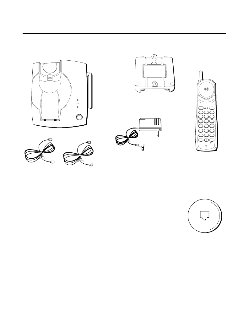
GETTING STARTED
Make sure your package includes the items shown here.
LINE 1
LINE 2
CHARGE
PAGE
PAGE
Wall mount
bracket
Base
AC power supply
Two telephone line cords
BEFORE YOU BEGIN
MODULAR JACK REQUIREMENTS
You need an RJ14 type modular jack or two RJ11 type
jacks. RJ11 is the most common type of phone jack.
Either might look like the one pictured here. If you don’t
have a modular jack, call your local phone company to
find out how to get one installed.
LINE 1 LINE 2
TALK
CHAN
HOLDLINE 2LINE 1
DEF3ABC
21
MNO6JKL5GHI
4
WXYZ9TUV8PQRS
7
TONE
OPER
0
#
*
MEMRE/PA MUTE
ON OFF RING
CONF
FLASH
PWR-ON OFF
CONF/
MUTE
BAT
LOW
Handset
4
Page 5

DIGITAL SECURITY SYSTEM
Your cordless phone uses a digital security system to provide protection
against false ringing, unauthorized access, and charges to your phone line.
When you place the handset in the base, the unit verifies its security code.
After a power outage or battery replacement, you should place the
handset in the base for about 20 seconds to reset the code.
IMPORTANT: Because cordless phones operate on electricity, you should
have at least one phone in your home that isn’t cordless, in case the power in
your home goes out.
INSTALLATION NOTE: Some cordless telephones operate at frequencies that
may cause interference to nearby TVs and VCRs. To minimize or prevent such
interference, the base of the cordless telephone should not be placed near or on
top of a TV or VCR. If interference continues, moving the cordless telephone
farther away from the TV or VCR will often reduce or eliminate the interference.
5
Page 6
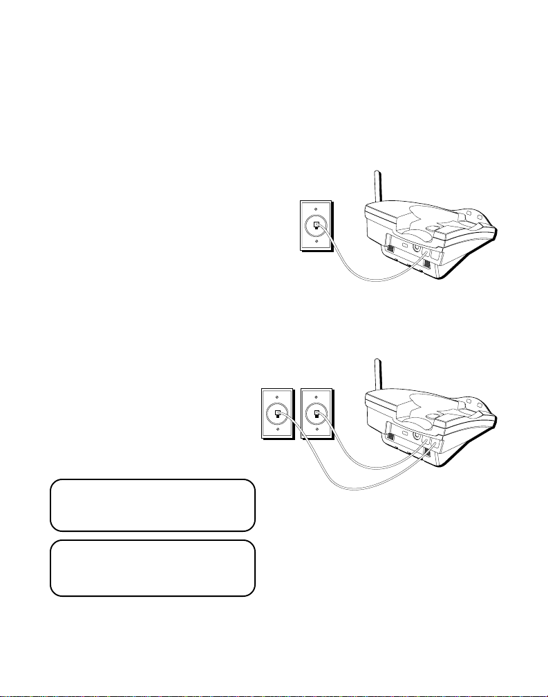
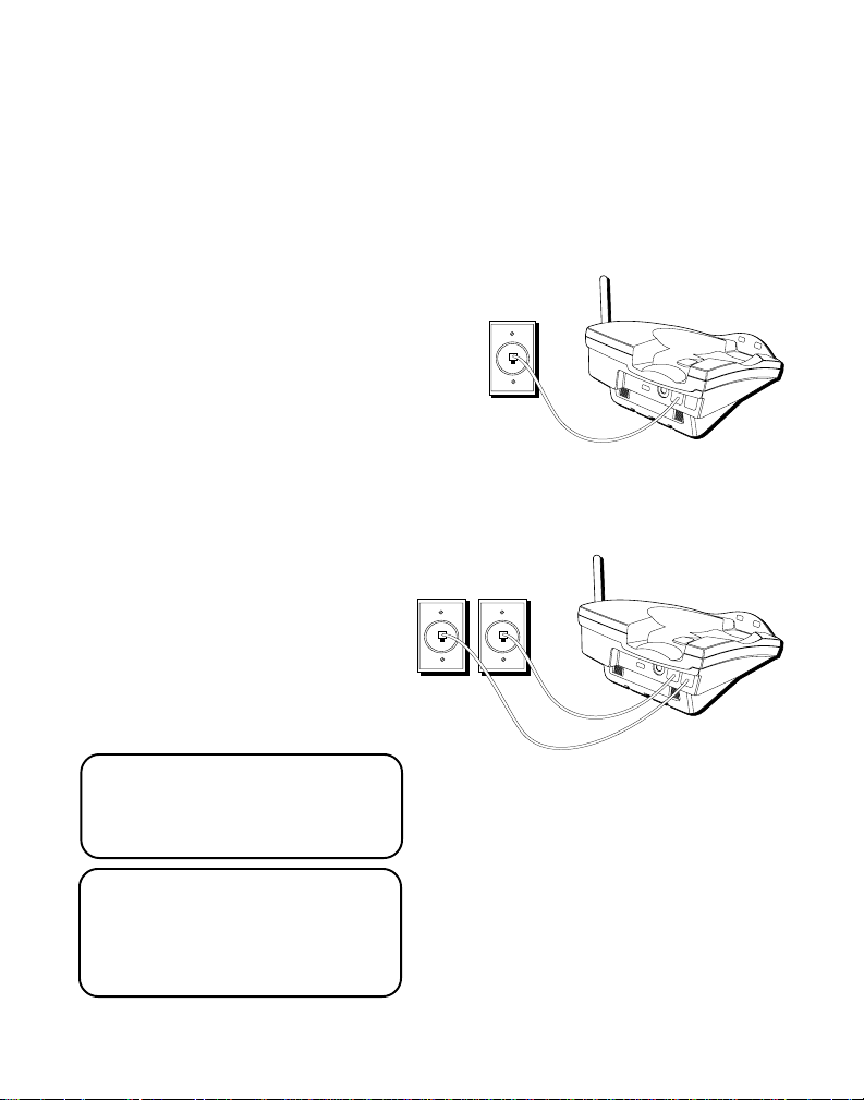
INSTALLATION OPTIONS
Although you can use your 2-line cordless telephone with a single phone
line, you must have two lines (separate phone numbers) to use a two-line
system. The following diagrams show two possible systems:
Two Lines on Single Modular Jack
One type of two-line phone
system uses a single RJ14
modular jack which contains both
phone lines. Connect the phone
cord to the L1 and L2 jack.
You must use a 4-conductor
telephone line cord like the ones
that are packed with your unit.
Each Line on a Separate Modular Jack
If you have two separate phone
jacks, each with its own line,
Line 2
connect one of the phone cords to
the L2 jack, and connect the
remaining phone cord to the L1
and L2 phone jack located on the
back of the phone.
NOTE: Connect the phone cord
from the L1 and L2 jack to the
outlet that you want to be line 1.
Line 1
NOTE: Two-line capability
requires two-line service from
your local telephone company.
6
Page 7

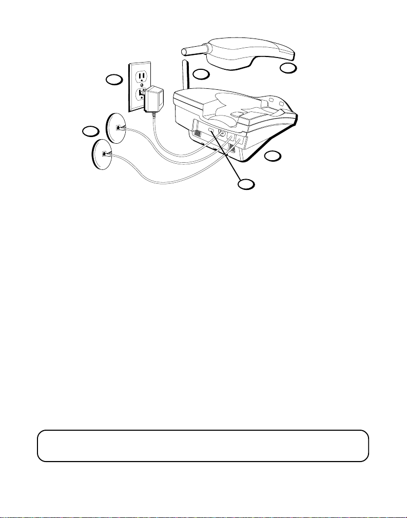
DESKTOP INSTALLATION
3
6
5
1
2
T/P switch
7
Two Lines on a Single Modular Jack
1. Make sure base plate is securely fastened.
2. Set the T/P switch to T for touch-tone service, or P for pulse (rotary)
service. If you don’t know which type of service you have, check with
the phone company.
3. Raise the base antenna.
4. Set the RING switch to ON so the handset rings for incoming calls.
5. Plug the telephone line cord into the L1 and L2 jack located on the back
of the phone and into a dual line modular jack.
6. Plug the power supply cord into the base and into an AC outlet.
7. Place handset in the base to charge for 12 hours. The CHARGE/PAGE
light comes on indicating that the battery is charging. If you don’t
charge the handset battery properly (for 12 hours) when you first set up
the phone, performance of the battery will be compromised.
CAUTION: Use only the Thomson power supply 5-2445(white)/5-2446(black)that is
compatible with this unit. Using other adapters may damage the unit.
7
Page 8
6
5
3
2
7
1
T/P switch
Each Line on a Separate Modular Jack
1. Make sure wall mount bracket is securely fastened.
2. Set the T/P switch to T for touch-tone service, or P for pulse (rotary)
service. If you don’t know which type of service you have, check with
the phone company.
3. Raise the base antenna.
4. Set the RING switch to ON so the handset rings for incoming calls.
5. Plug one of the telephone line cords into the L2 jack and into a single
line modular jack. Connect the remaining phone cord to the L1 and L2
phone jack located on the back of the phone and into a single line
modular jack.
6. Plug the power supply cord into the base and into an AC outlet.
7. Place handset in the base to charge for 12 hours. The CHARGE/PAGE
light comes on indicating that the battery is charging. If you don’t
charge the handset battery properly (for 12 hours) when you first set up
the phone, the battery’s long-term performance will be compromised.
CAUTION: Use only the Thomson power supply 5-2445(white)/5-2446(black)that is
compatible with this unit. Using other adapters may damage the unit.
8
Page 9

WALL MOUNT INSTALLATION
1
Two Lines on a Single Modular Jack
1. Remove the handset hook; turn it
upside down, and put it back in the
slot. You need to do this so the
handset doesn’t fall out of the base.
2. Plug the telephone line cord into the
jack marked L1 and L2 on the back of
the unit and plug the other end into a
modular wall jack.
3. Connect the power supply adapter to
the POWER 9V DC jack on the back of
the unit. Then thread it through the
bottom of base.
4. Reverse the direction of the wall
mount bracket and replace it by
putting the tabs into the slots on the
top of the unit first and snapping the
bottom tabs into place.
5. Plug the telephone line cord into the
dual line modular jack.
6. Slip the mounting holes over the wall
plate posts and slide the unit down
firmly into place. (Wall plate not
included.)
2
3
4
5
CAUTION: Use only the Thomson power supply 5-2445(white)/5-2446(black)that is
compatible with this unit. Using other adapters may damage the unit.
9
Page 10

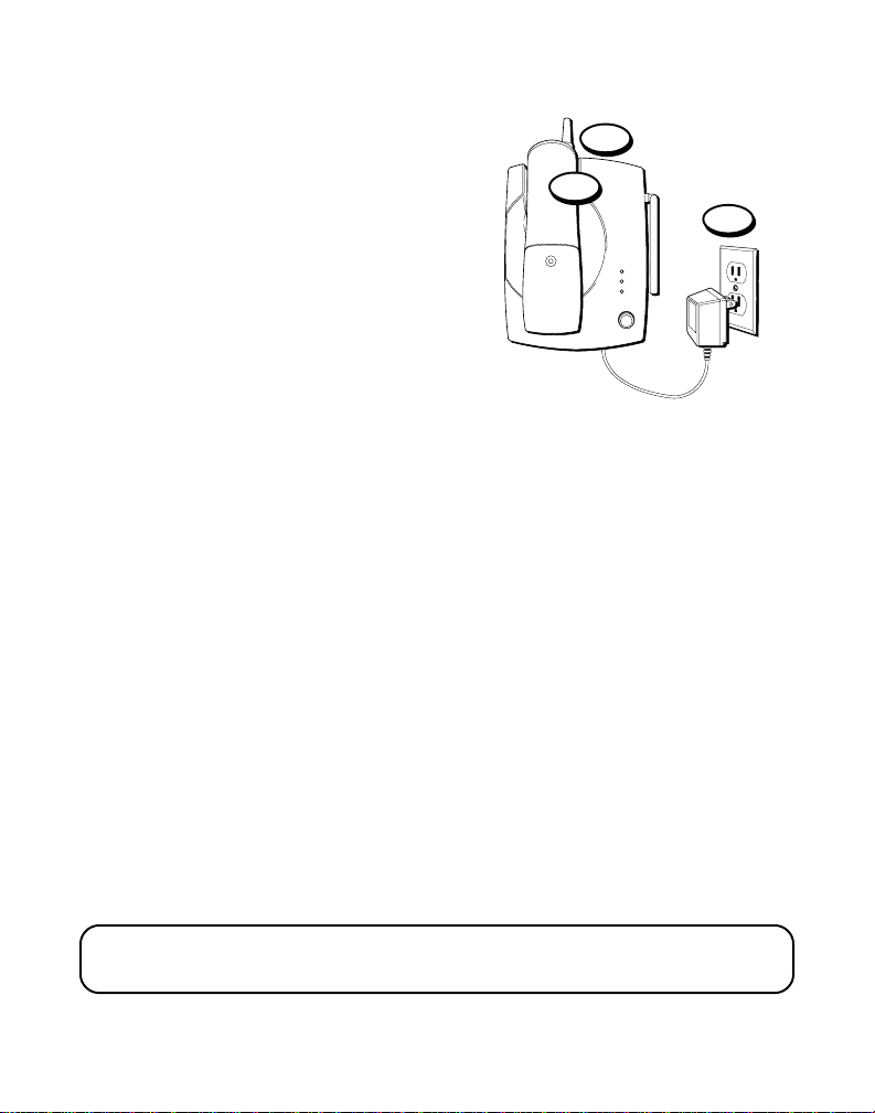
7. Set the T/P switch to T if you have
PAGE
LINE 1
LINE 2
CHARGE
PAGE
touch-tone service or to P (pulse) if
you have rotary dial service.
8. Set the RING switch to ON so the
handset rings for incoming calls.
9. Plug the power supply adapter into an
AC outlet and raise the antenna.
10.Place the handset in the base to
charge for 12 hours. The CHARGE/
PAGE light comes on. If you don’t
charge the handset battery properly
(for 12 hours) when you first set up
the phone, the battery’s long-term
performance will be compromised.
10
9
CAUTION: Use only the Thomson power supply 5-2445(white)/5-2446(black)that is
compatible with this unit. Using other adapters may damage the unit.
10
Page 11
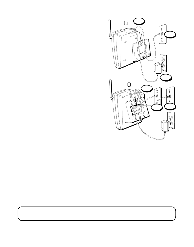
Each Line on a Separate Modular Jack
1. Remove the handset hook; turn it
upside down, and put it back in the slot.
You need to do this so the handset
doesn’t fall out of the base.
2. Plug the telephone line cord into the
jack marked L1 and L2 on the back of
the unit and plug the other end into a
modular wall jack.
3. Plug the remaining telephone line cord
into the L2 jack on the back of the unit.
4. Connect the power supply adapter to
the POWER 9V DC jack on the back of
the unit, and then thread it through the
bottom of base.
5. Reverse the direction of the base plate
and replace it by putting the tabs into
the slots on the top of the unit first, and
then by snapping the bottom tabs into
place.
6. Plug the telephone line cord from the
L1 and L2 jack into a single line
modular jack that you want to be line 1.
7. Plug the other telephone line cord into
the single line modular jack you want to
be line 2.
1
2
4
5
7
6
CAUTION: Use only the Thomson power supply 5-2445(white)/5-2446(black)that is
compatible with this unit. Using other adapters may damage the unit.
11
Page 12
8. Slip the mounting holes over the wall
PAGE
LINE 1
LINE 2
CHARGE
PAGE
plate posts and slide the unit down
firmly into place. (Wall plate not
included.)
9. Set the T/P switch to T if you have
touch-tone service or to P (pulse) if
you have rotary dial service.
10.Set the RING switch to ON so the
handset rings for incoming calls.
11.Plug the power supply adapter into an
AC outlet and raise the antenna.
12.Place the handset in the base to
charge for 12 hours. The CHARGE/
PAGE light comes on. If you don’t
charge the handset battery properly
(for 12 hours) when you first set up
the phone, the battery’s long-term
performance will be compromised.
9
12
11
CAUTION: Use only the Thomson power supply 5-2445(white)/5-2446(black)that is
compatible with this unit. Using other adapters may damage the unit.
12
Page 13

CHAN
MNO
6
JKL
5
GHI
4
DEF
3
ABC
21
WXYZ
9
TUV
8
PQRS
7
#
OPER
0
TONE
*
TALK
HOLDLINE 2LINE 1
CONF
ON OFF RING
FLASH
PWR-ON OFF
MEMRE/PA MUTE
LINE 1 LINE 2
CONF/
MUTE
BAT
LOW
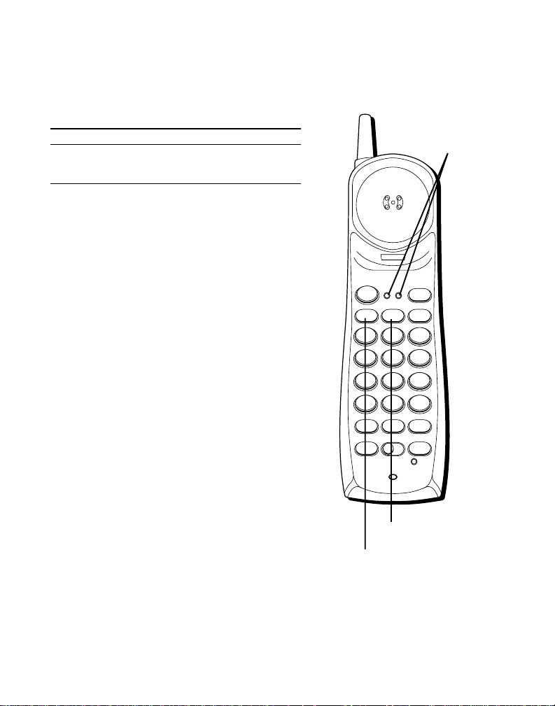
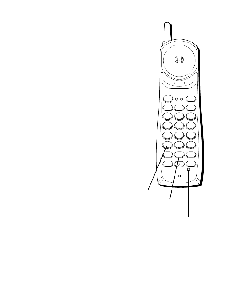
CORDLESS PHONE BASICS
MAKING A CALL
After initial set up, put handset in the
base for 12 hours to charge the battery.
The cordless phone automatically selects
the last line you used. The only two
things you need to know to make a call
are:
1. Press LINE 1 or LINE 2 to select a line
before you dial.
2. When finished, press LINE 1 or LINE 2
(whichever line you are talking on).
Otherwise, it works just like any other
phone.
NOTE: You can press TALK instead of
pressing LINE 1 or LINE 2. The phone
defaults to the last line from which you
dialed.
TALK button
LINE 1 and LINE 2
indicator lights
LINE 2 button
LINE 1 button
13
Page 14
LINE INDICATOR LIGHTS
CHAN
MNO
6
JKL
5
GHI
4
DEF
3
ABC
21
WXYZ
9
TUV
8
PQRS
7
#
OPER
0
TONE
*
TALK
HOLDLINE 2LINE 1
CONF
ON OFF RING
FLASH
PWR-ON OFF
MEMRE/PA MUTE
LINE 1 LINE 2
CONF/
MUTE
BAT
LOW
Above each line button is a Red indicator
light which informs you the status of
each line.
Light Status
Solid Line is in use
Blinking Line on hold
DUAL RINGER TONES
Your cordless telephone has separate
and distinct ringer sounds for LINE 1 and
LINE 2. This will allow you to determine
the line of an incoming call, even in
another room. If you are talking on one
line and someone calls on the other line,
the phone alerts you by sending a signal
to the handset’s earpiece.
LINE 1 and LINE 2
indicator lights
14
LINE 2 button
LINE 1 button
Page 15

REDIAL
CHAN
MNO
6
JKL
5
GHI
4
DEF
3
ABC
21
WXYZ
9
TUV
8
PQRS
7
#
OPER
0
TONE
*
TALK
HOLDLINE 2LINE 1
CONF
ON OFF RING
FLASH
PWR-ON OFF
MEMRE/PA MUTE
LINE 1 LINE 2
CONF/
MUTE
BAT
LOW
Press the TALK button, then press the RE/
PA (redial/pause) button to redial the last
number you called (up to 32 digits).
RECEIVING A CALL
To answer a call when the handset is out
of the base, you must press TALK or the
LINE 1 or LINE 2 button.
FLASH
Use the FLASH button to activate custom
calling services such as call waiting or call
transfer, which are available through your
local phone company.
TIP: If you press the TALK button to
activate custom calling services such as
call waiting, you’ll hang up the phone.
Press FLASH instead.
TALK button
FLASH button
RE/PA (redial/pause) button
15
Page 16
CHAN
MNO
6
JKL
5
GHI
4
DEF
3
ABC
21
WXYZ
9
TUV
8
PQRS
7
#
OPER
0
TONE
*
TALK
HOLDLINE 2LINE 1
CONF
ON OFF RING
FLASH
PWR-ON OFF
MEMRE/PA MUTE
LINE 1 LINE 2
CONF/
MUTE
BAT
LOW
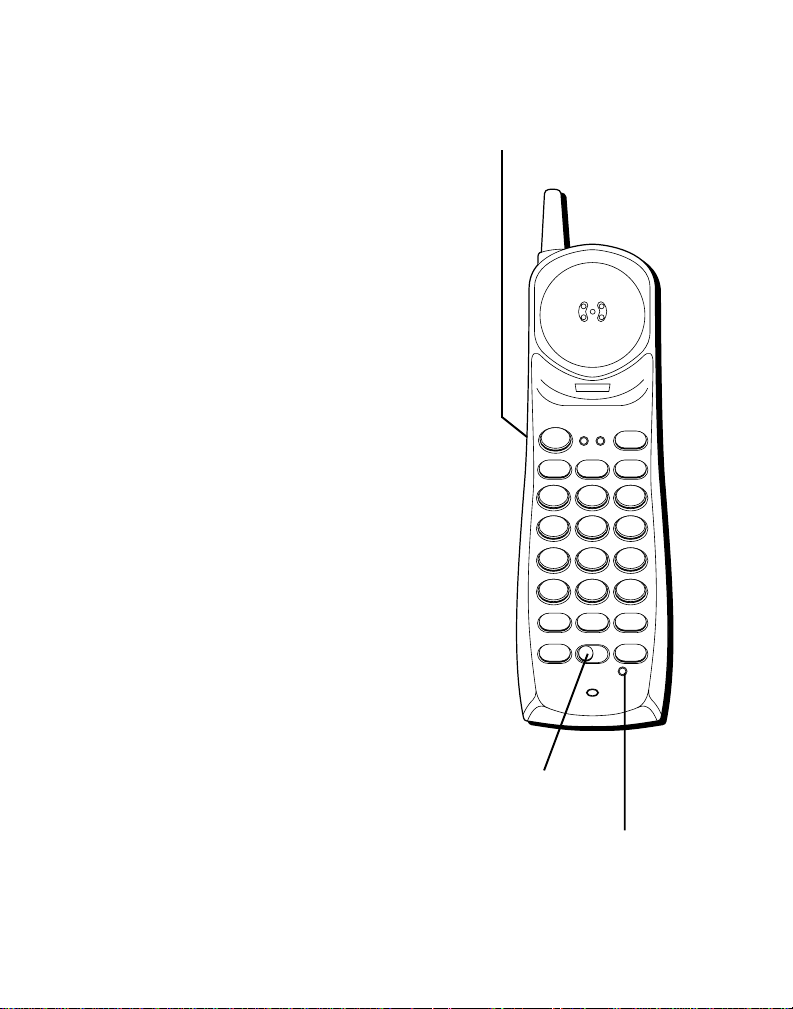
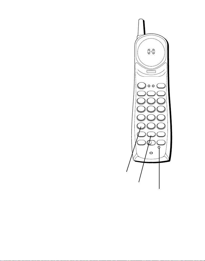
VOLUME
Controls the volume of the handset's
earpiece.
RINGER AND POWER
This is a 3-position switch that controls
the ringer and handset power.
When you move the switch to the left, the
power is on and the ringer is on.
When you move the switch to the middle
position, the power is on, but the ringer is
off.
When you move the switch to the far
right, the power is off and the ringer is off
which saves battery power. You must turn
PWR to ON (by sliding the switch to the
middle or left position) in order to make
calls or receive calls.
VOL switch (on the side
of the handset)
16
RING/PWR switch
CONF/MUTE/BAT
LOW indicator light
Page 17
MUTE
CHAN
MNO
6
JKL
5
GHI
4
DEF
3
ABC
21
WXYZ
9
TUV
8
PQRS
7
#
OPER
0
TONE
*
TALK
HOLDLINE 2LINE 1
CONF
ON OFF RING
FLASH
PWR-ON OFF
MEMRE/PA MUTE
LINE 1 LINE 2
CONF/
MUTE
BAT
LOW
Use the MUTE button to interrupt a
phone conversation to talk privately with
someone else in the room.
1. Press MUTE to activate mute feature.
2. Press MUTE again to turn it off.
TEMPORARY TONE
This feature enables pulse (rotary)
service phone users to access touch-tone
services offered by banks, credit card
companies, etc., by pressing the TONE
button to temporarily make the phone
touch-tone compatible. To get information about your bank account, for example, you would:
1. Press the TALK button.
2. Call the bank’s information line.
3. Press the TONE button after your call
is answered.
4. Follow the voice instructions to
complete your transaction.
5. Hang up when finished. The phone
returns to pulse (rotary) service.
TONE button
MUTE button
CONF/MUTE/BAT
LOW indicator light
17
Page 18

HOLD
CHAN
MNO
6
JKL
5
GHI
4
DEF
3
ABC
21
WXYZ
9
TUV
8
PQRS
7
#
OPER
0
TONE
*
TALK
HOLDLINE 2LINE 1
CONF
ON OFF RING
FLASH
PWR-ON OFF
MEMRE/PA MUTE
LINE 1 LINE 2
CONF/
MUTE
BAT
LOW
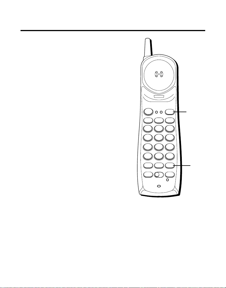
You can use the HOLD button to interrupt
a phone conversation without hanging
up.
1. Press HOLD to place the active line on
hold.
2. Press the LINE button for that call to
resume the conversation.
CONFERENCE
You can use the conference call feature
when you have callers on both lines and
want to have a three-way conversation.
1. Press HOLD to place the party on hold.
2. Press the other LINE button.
3. Dial the number of the second party.
4. Press the CONF button. You can now
talk to both parties.
5. When finished, press LINE 1 and LINE
2 or place the handset in the base to
hang up.
NOTE: If any time you want to disconnect
a party, press the line button for that
party. You can then continue talking to
the person on the other line.
18
HOLD
button
CONF
button
Page 19

PAGING THE HANDSET
Press the PAGE button on the base or
to locate a misplaced handset. When
you press the PAGE button, the
handset beeps for two minutes. Press
any key when you locate the handset.
Remember that the PWR-ON OFF
switch must be ON in order for the
handset to beep.
NOTE: You can turn the ringer off
and still page the handset if you put
the PWR-ON OFF switch in the
middle position.
LINE 1
LINE 2
CHARGE
PAGE
PAGE
PAGE
button
19
Page 20
ADVANCED FEATURES
CHANNEL (CHAN)
If you ever experience any interference or
don’t have clear voice quality, press the
CHAN button on the handset to advance
to another channel.
THE MEMORY FEATURE
Store up to 10 numbers in memory for
quick dialing.
STORING A NUMBER IN MEMORY
The phone must be off (PWR button
on, but no dial tone) when you store
numbers.
1. Press the MEM button.
2. Dial the number (up to 24 digits).
3. Press MEM.
4. Press any number key (0-9) to store
the phone number in that memory
location.
LINE 1 LINE 2
TALK
GHI
4
PQRS
7
TONE
*
FLASH
ABC
21
JKL
5
TUV
8
OPER
0
ON OFF RING
PWR-ON OFF
CHAN
HOLDLINE 2LINE 1
DEF
MNO
WXYZ
#
MEMRE/PA MUTE
CONF
CONF/
MUTE
BAT
LOW
CHAN
button
3
6
9
MEM
button
20
Page 21

CHANGING A STORED NUMBER
Use the same procedure to change a stored number as you do to store a
number— you’re just replacing the phone number with a new one.
S
TORING A REDIAL NUMBER
1. Press MEM.
2. Press RE/PA (redial/pause).
3. Press MEM.
4. Press any number key (0-9) to store the phone number in that memory
location.
S
TORING A PAUSE IN MEMORY
Use the RE/PA button to insert a pause when a delay is needed in the
dialing sequence (for example, when you must dial a 9 to get an outside
line or when you must enter codes to access your bank’s information line).
If you need to dial 9 to get an outside line and want to store a number in
memory without having to dial 9 each time, you would:
1. Press MEM.
2. Press 9.
3. Press RE/PA (redial/pause).
4. Dial the phone number you want to store in memory.
5. Press MEM.
6. Press any number key (0-9) to store the phone number in that memory
location.
TIP: If you need a longer pause, press RE/PA button more times.
21
Page 22

D
IALING A STORED NUMBER
1. Press the TALK button to get a dial tone.
2. Press MEM and then press the number for that memory location.
C
HAIN DIALING FROM MEMORY
Use this feature to make calls which require a sequence of numbers, for
instance if you use a calling card for a frequently called long distance
number. Basically, you dial each part of the sequence from memory. The
following example shows how you can usechain dialing to make a call
through a long distance service:
The Number For Memory Location
Long distance access number 7
Authorization code 8
Frequently called long distance number 9
1. Press the TALK button to get a dial tone.
2. Press the MEM button and then press 7.
3. When you hear the access tone, press MEM and then press 8.
4. At the next access tone, press MEM and then 9.
22
Page 23
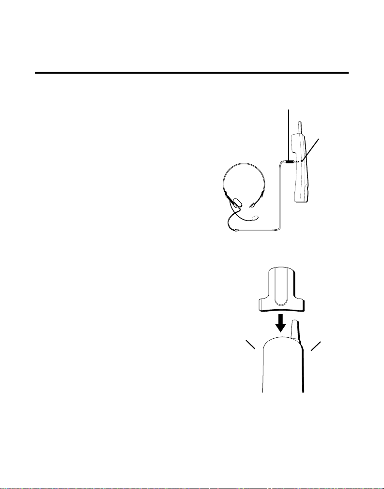
HEADSET AND BELT CLIP OPERATION (OPTIONAL)
CONNECTING A HEADSET TO
HANDSET
THE
For hands free conversation, connect the
headset (optional) to the HEADSET jack as
shown. The handset receiver and microphone are disabled when the headset is
connected.
Adjust the headset to rest comfortably on
top of your head and over your ear. Move
the microphone to approximately 2 to 3
inches from your mouth.
• Press the TALK button or LINE 1 or 2 to
answer or place a call before using the
headset.
CONNECTING THE BELT CLIP
There are two slots, one on each side of the
handset.
• Attach the belt clip (optional) by insert-
ing the sides of the belt clip into the
slots. Snap the ends of the belt clip into
place.
Slot for
belt clip
Headset plug (2.5mm)
HEADSET
jack
H
E
A
D
S
E
T
Slot for
belt clip
23
Page 24
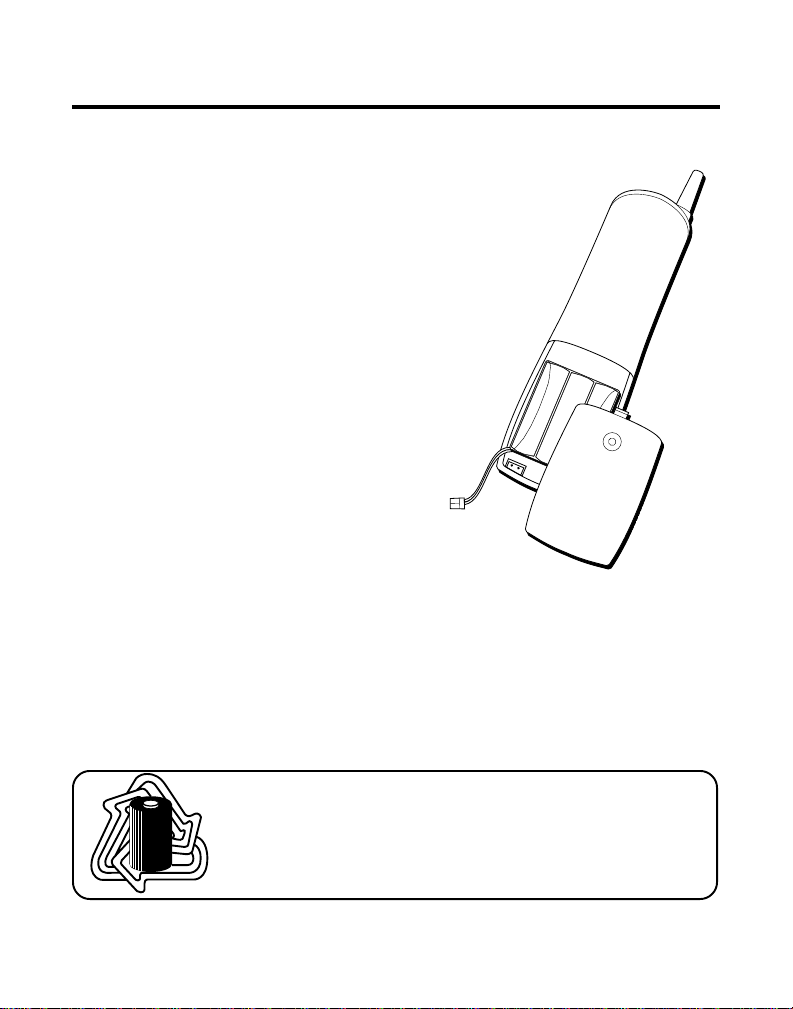
CHANGING THE BATTERY
Make sure RING/POWER switch is OFF
before you replace battery.
1. Remove the battery compartment door.
2. Disconnect the cord attached to the
battery pack and remove the battery
pack from the handset.
3. Insert the new battery pack and connect
the cord into the jack inside the handset.
4. Put the battery compartment door back
on.
5. If you don’t charge the handset
battery properly (for 12 hours) when
you first set up the phone and/or
when you install a new battery pack,
the battery’ s long-term performance
will be compromised.
BATTERY SAFETY PRECAUTIONS
• Do not burn, disassemble, mutilate, or puncture. Like other batteries of
this type, toxic materials could be released which can cause injury.
• To reduce the risk of fire or personal injury, use only the battery listed in
the User’s Guide.
• Keep batteries out of the reach of children.
24
RBRC
RBRC
Ni-Cd
NOTE: The RBRC seal on the battery used in your Thomson
Consumer Electronics product indicates that we are participating in a
program to collect and recycle Nickel Cadmium batteries throughout
the United States of America. Please call 1-800-8-BATTERY for
information or contact your local recycling center.
Page 25

TROUBLESHOOTING GUIDE
In case of difficulty, please check the following Troubleshooting Guide
before seeking service.
Problem Solution
No dial tone • Check installation:
— Is the base power cord connected to a working outlet?
— Is LINE 1/LINE 2 light on?
— Is the telephone line cord connected to the base unit and
the wall jack?
— Is a headset connected to the handset? The handset
receiver and microphone are temporarily disabled when
you connect the headset
• Disconnect the base from the wall jack and connect another
phone to the same jack. If there is no dial tone in the second
phone, the problem might be your wiring or local service.
• Is the handset out of the base unit’s range?Move closer to the
base unit.
• Make sure the battery is properly charged (12 hours).
• Is the battery pack installed correctly?
• If the phone still does not work, disconnect the power cord
and remove the battery pack. Then reconnect the power cord
and reinstall the battery pack. Place handset in the base for
10 seconds to allow it to reinitialize.
• Make sure RING/PWR switch on the handset is turned on.
• Make sure the base plate is attached properly.
Dial tone is OK, but • Make sure the T/P switch on the base is set
can’t dial out correctly.
Handset does not ring • Make sure the RING/PWR switch on the handset is turned to
Cannot hear phone • Set the volume control on side of handset to HI.
conversation
You experience static, • Change channels.
noise, or fading in • Is handset out of range? Move closer to the base.
and out • Does the base need to be relocated?
ON (the far left position).
• You may have too many extension phones on your line. Try
unplugging some phones.
• See solutions for “No dial tone.”
• Charge handset battery.
• Make sure base is not plugged into an outlet with another
household appliance.
25
Page 26

TROUBLESHOOTING GUIDE (CONTINUED)
Problem Solution
Cannot hear the • Set the PWR switch on the handset to ON (the far left
Page alert tone
Range is shorter • Press the CHAN button during the conversation to select a
than normal new channel.
Battery will not hold a • Be sure you are sufficiently charging the battery. When the
charge OR is fully charged battery has been charged for 12 hours, you can expect
and the BAT LOW lights approximately 4 hours of talk time.
position).
• Position the base antenna upward.
• Check to be sure battery contacts on both the handset and
the base are making contact and are clean; free of dirt or lint.
• When the handset is placed in the base, check that the base
CHARGE light is on.
BAT LOW light stays on • Place handset in base for 10 seconds to reset the
Memory Dialing
doesn’t work
Unit locks up • If the phone still does not work, disconnect the power cord
no communication and remove the battery pack. Then reconnect the power cord
between the base and reinstall the battery pack. Place handset in the base for
and the handset 10 seconds to allow it to reinitialize.
that doesn’t work, charge battery for 12 hours.
• Did you program the memory location keys correctly?
• Did you follow proper dialing sequence?
• Make sure T/P switch is correctly set.
• If a power outage occurs while the handset is away from the
base, the handset must be returned to the base when the
power returns.
phone. If
26
Page 27

GENERAL PRODUCT CARE
To keep your telephone working and looking good, follow
these guidelines:
• Avoid putting the phone near heating appliances and devices that
generate electrical noise (for example, motors or fluorescent lamps).
• DO NOT expose to direct sunlight or moisture.
• Avoid dropping the handset, as well as other rough treatment to
the phone.
• Clean the phone with a soft cloth.
• Never use a strong cleaning agent or abrasive powder because this will
damage the finish.
• Retain the original packaging in case you need to ship the phone at a
later date.
• Periodically clean the charge contacts on the handset and base with a
eraser.
CAUSES OF POOR RECEPTION
• Aluminum siding.
• Foil backing on insulation.
• Heating ducts and other metal construction can shield radio signals.
• You’r e too close to appliances such as microwaves, stoves,
computers, etc.
• Atmospheric conditions, such as strong storms.
• Base is installed in the basement or lower floor of the house.
• Base is plugged into an AC outlet with other electronic devices.
• Baby monitor is using the same frequency.
• Handset battery is low.
• You’r e out of range of the base.
27
Page 28

S
ERVICE
FCC requires this product to be serviced only by the manufacturer or its
authorized service agents. In accordance with FCC requirements, changes
or modifications not expressly approved by Thomson Consumer Electronics could void the user’s authority to operate this product. For instructions
on how to obtain service, call Consumer Information, 1-800-448-0329.
Attach your sales receipt to the booklet for future reference or jot down the
date this product was purchased or received as a gift. This information will
be valuable if service should be required during the warranty period.
Purchase date _____________ Name of store_____________________
28
Page 29

✂
CUSTOMER: CUT ALONG DOTTED LINE.
TOTAL
QUANTITY
$18.35
$21.35
PRICE*
$5.61
$18.35
$36.35
$5.00
1-800-338-0376)
ALL
C
OR
(
5-2445
5-2450
5-2440
CATALOG NUMBER
ORM
F
RDER
O
DESCRIPTION
Belt clip
Replacement handset battery
AC power supply adapter (white)
ACCESSORY
*Prices are subject to change without notice.
Total Merchandise.........................................$_______________
Sales Tax........................................................$_______________
We are required by law to collect the appropriate sales tax for each individual state,
county, and locality to which the merchandise is being sent.
Use VISA or Master Card or Discover preferably. Money order or check must be in U.S.
currency only. No COD or Cash. All accessories are subject to availability. Where
applicable, we will ship a superseding model.
5-2446
5-2425
Headset
AC power supply adapter (black)
For credit card purchases
Your complete charge card number, its expiration date and your
signature are necessary to process all charge card orders.
Copy your complete account number from your VISA card.
My card expires:
Shipping/Handling....................................... $_______________
Total Amount Enclosed.................................$_______________
Mail order form and money order or check (in U.S. currency)
made payable to Thomson Consumer Electronics, Inc. to:
TCE
Mail Order Department
P.O. Box 8419
Ronks, PA 17573-8419
Name_______________________________________________________
Address_____________________________________ Apt.____________
City ________________________State________ ZIP_________________
Daytime Phone Number ( )_______________________________
Please make sure that this form has been filled out completely.
Authorized Signature
Copy the number above your
Copy your complete account number from your
Master Card or Discover.
name on the Master Card
My card expires:
____________________________________________________________________
29
Page 30

30
Page 31

INDEX
A
Accessory Order Form 29
Advanced Features 20
B
Battery Safety Precautions 24
Before You Begin 4
C
Causes of Poor Reception 27
Chain Dialing from Memory 22
Changing a Stored Number 21
Changing the Battery 24
Channel (CHAN) 20
Conference 18
Connecting a headset to the handset 23
Connecting the Belt Clip 23
Cordless Phone Basics 13
D
Desktop Installation 7
Dialing a Stored Number 22
Digital Security System 5
Dual Ringer Tones 14
F
FCC Registration Information 2
Flash 15
G
GeneralProduct Care 27
Getting Started 4
H
Headset and Belt Clip Operation 23
Hearing Aid Compatibility 2
Hold 18
I
Installation Options 6
Interference Information 2
Introduction 3
L
Limited Warranty 32
Line Indicator Lights 14
M
Making a Call 13
Modular Jack Requirements 4
Mute 17
P
Paging the Handset 19
R
Receiving a Call 15
Redial 15
Ringer and Power 16
S
Service 28
Storing a Number in Memory 20
Storing a Pause in Memory 21
Storing a redial number 21
T
Temporary Tone 17
The Memory Feature 20
Troubleshooting Guide 25
V
Volume 16
W
Wall Mount Installation 9
31
Page 32

LIMITED WARRANTY
What your warranty covers:
• Any defect in materials or workmanship.
For how long after your purchase:
• One year.
(The warranty period for rental units begins with the first rental or 45 days from date of shipment to
the rental firm, whichever comes first.)
What we will do:
• Provide you with a new or, at our option, a refurbished unit.
• The exchange unit is under warranty for the remainder of the original product’s warranty period.
How to make a warranty claim:
• Properly pack your unit. Include any cables, etc., which were originally provided with the product. We
recommend using the original carton and packing materials.
• Include evidence of purchase date such as the bill of sale. Also print your name and address and a
description of the defect. Send via standard UPS or its equivalent to:
Thomson Consumer Electronics, Inc.
11721 B Alameda Ave.
Socorro, Texas 79927
• Pay any charges billed to you by the Exchange Center for service not covered by the warranty.
• Insure your shipment for loss or damage. Thomson accepts no liability in case of damage or loss en
route to Thomson.
• A new or refurbished unit will be shipped to you freight prepaid.
What your warranty
• Customer instruction. (Your Owner’s Manual provides information regarding operating instructions
and user controls. For additional information, ask your dealer.)
• Installation and set-up service adjustments.
• Batteries.
• Damage from misuse or neglect.
• Products which have been modified or incorporated into other products.
• Products purchased or serviced outside the USA.
• Acts of God, such as but not limited to lightning damage.
Product Registration:
• Please complete and mail the Product Registration Card packed with your unit. It will make it easier to
contact you should it ever be necessary. The return of the card is not required for warranty coverage.
How state law relates to this warranty:
• This warranty gives you specific legal rights, and you may have other rights which vary from state to
state.
If you purchased your product outside the USA:
• This warranty does not apply. Contact your dealer for warranty information.
does not
cover:
Model 26925A
15417530 (Rev. 1, E/S)
99-37
Printed in Thailand
P.O. Box 1976, Indianapolis, IN 46206
© 1999 Thomson Consumer Electronics, Inc.
Trademark(s) ® Registered
Marca(s) Registrada(s)
Page 33

26925
32-Canales
900MHz Inalámbrico de dos líneas
Teléfono con audífonos
Guía del usuario
Creamos cosas buenas para la vida
Page 34

INFORMACIÓN DE LA REGISTRACIÓN DE LA FCC
Su equipo telefónico de la ha sido registrado con la Comisión Federal de Comunicaciones (FCC) y está en acuerdo con las Partes 15 y
68 de las Regulaciones y Reglas de la FCC.
1 Notificación a la Compañía Telefónica Local
Al fondo de este equipo Ud. hallará un rótulo indicando, entre otra información, el número de la Registración con la FCC y el
Número del Equivalente Timbre (REN) para este equipo. Ud. deberá, a petición, proveer esta información a su compañía
telefónica.
El REN es útil para determinar el número total de artefactos que Ud. puede conectar a su línea telefónica, todavía asegurando que
todos estos artefactos sonarán cuando se llame su número telefónico. En la mayoría de las áreas (pero no en todas), el total de
los números REN de todos los artefactos conectados a una línea no debe exceder 5. Para estar seguro del número total de
artefactos que Ud. pueda conectar a su línea (determinado por el REN), Ud. deberá ponerse en contacto con su compañía
telefónica local.
NOTAS:
• No se puede usar este equipo con un teléfono de previo pago proveído por la compañía telefónica.
• Las líneas compartidas son sujetas a las tarifas del estado, y por eso, es posible que Ud. no pueda usar su propio equipo
telefónico si Ud. estuviera compartiendo la misma línea telefónica con otros abonados.
• Se debe notificar la compañía telefónica cuando se desconecte permanentemente su teléfono de la línea.
2 Derechos de la Compañía Telefónica
Si su equipo causase algún problema en su línea que pudiera dañar la red telefónica, la compañía telefónica siempre que sea
posible le avisará de la posible interrupción temporal de su servicio. En caso que la compañía no pudiera avisarle de antemano y
hubiera necesidad de tomar tal acción, la compañía telefónica podrá interrumpir su servicio inmediatemente. En caso de tal
interrupción telefónica temporal la compañía debe : (1) darle aviso al momento de tal interrupción temporal de servico, (2)
concederle a Ud. la oportunidad de corregir la situación, (3) informarle a Ud. de sus derechos de presentar una questa a la
Comisión de acuerdo con los procedimientos dictados en la Subparte E de la Parte 68 de las Regulaciones y Reglas de la FCC.
La compañía telefónica puede hacer los cambios en sus instalaciones de comunicación, en equipos, en sus funcionamientos o
procedimientos que digne necesarios para el manejo de sus negocios y que no sean incompatibles con las Reglas y Regulaciones
de l a FCC. Si estos cambios pudieran alterar el uso o el funcionamiento de su equipo telefónico, la compañía telefónica deberá
darle aviso adecuado en escrito para que Ud. goce de un servico ininterrumpido.
INFORMACIÓN DE INTERFERENCIAS
Este artefacto cumple con la Parte 15 de las Reglas de la FCC. Su funcionamiento es sujeto a las dos condiciones siguientes: (l) Este
artefacto no puede causar interferencia dañosa, y (2) Este artefacto debe aceptar cualquier interferencia recibida, incluyendo
interferencia que puede causar un funcionamiento no deseado.
Este equipo ha sido probado y cumple con los límites para un artefacto digital de la Clase B, de conformidad con la Parte 15 de las
Reglas de la FCC. Estos límites han sido diseñados para proporcionar una protección razonable contra una interferencia dañosa que
pueda existir en una instalación doméstica.
Este equipo genera, usa y puede radiar la energía de frecuencia de una radio y, si no fuera instalado y usado de acuerdo con las
instrucciones, puede causar interferencia dañosa a las transmisiones radiales. Sin embargo, no hay garantía que la interferencia no
ocurrirá en una instalación en particular.
Si este equipo causa en efecto una interferencia dañosa a la recepción de la radio o de la televisión, lo cual puede ser determinado
apagando y prendiendo el equipo, le animamos a Ud. de tratar de corregir la interferencia por medio de una (o más) de las
sugerencias siguientes:
• Cambie la posición o la ubicación de la antena (quiere decir la antena de la radio o de la televisión que está recibiendo la
interferencia).
• Cambie la posición o cambie la ubicación y aumente la distancia entre el equipo de telecomunicaciones y la antena receptora de
la radio o de la televisión que está recibiendo la interferencia.
• Conecte el equipo de telecomunicaciones a una toma en un circuito diferente del circuito al cual la antena receptora esté
conectada.
Si estas medidas no eliminan la interferencia, favor de consultar a su distribuidor o a un técnico de radio/televisión experto por otras
sugerencias. También, la Comisión Federal de Comunicaciones (FCC) ha preparado un folleto muy útil, “How To Identify and Resolve
Radio/TV Interference Problems” (“Como Identificar y Resolver Problemas de Interferencia de Radio/Televisión”). Este folleto se puede
obtener del U.S. Goverment Printing Office, Washington, D.C. 20402. Favor de especificar el número 004-000-00345-4 cuando haga su
pedido.
COMPATIBILIDAD CON AUDÍFONOS
Se juzga que este teléfono es compatible con audífonos, en base a las normas de la FCC.
EL NÚMERO DE LA FCC EST A SITUADO EN LA PARTE INFERIOR DE LA CABINA
EL NUMERO DE REN ESTA SITUADO EN LA PARTE INFERIOR DE LA CABINA
2
Page 35

INTRODUCCCIÓN
Su teléfono inalámbrico 900 MHz está diseñado para darle flexibilidad de
utilización y rendimiento de alta calidad. Para aprovechar al máximo su teléfono
inalámbrico, le sugerimos que dedique ahora algunos minutos a la lectura de este
manual de instrucciones.
CONTENIDO
INFORMACIÓN DE LA REGISTRACIÓN DE
FCC ................................... 2
LA
NFORMACIÓN DE INTERFERENCIAS .... 2
I
COMPATIBILIDAD CON AUDÍFONOS .... 2
NTRODUCCCIÓN.................................... 3
I
ARA EMPEZAR..................................... 4
P
ANTES DE COMENZAR ........................ 4
EQUISITOS PARA EL ENCHUFE HEMBRA
R
MODULAR
SISTEMA DE SEGURIDAD DIGITAL......... 5
PCIONES DE INSTALACIÓN ................. 6
O
NSTALACIÓN SOBRE ESCRITORIO .......... 7
I
MONTAJE EN PARED .......................... 9
OCIONES BÁSICAS SOBRE EL TELÉFONO
N
INALÁMBRICO
PARA LLAMAR ................................ 13
NDICADORES LUMINOSOS DE LÍNEA .14
I
IMBRE DE DOS TONOS ................. 14
T
VOLVER A MARCAR....................... 15
ECEPCIÓN DE LLAMADAS ................. 15
R
LASH ........................................... 15
F
VOLUMEN ...................................... 16
IMBRE Y ALIMENTACIÓN (RINGER AND
T
POWER
MUTE (MUDO)................................ 17
ONO TEMPORAL............................. 17
T
OLD (ESPERA) .............................. 18
H
CONFERENCE (CONFERENCIA) ............ 18
ÚSQUEDA DEL AURICULAR ............... 19
B
UNCIONES AVANZADAS ....................... 20
F
CANAL (CHAN) ............................ 20
................................. 4
................................... 13
) .................................. 16
ADVERTENCIA:
PREVENIR EL RIESGO DE UNFUEGO O DE
UNA SACUDIDA ELECTRICA, NO EXPONGA
ESTE APARA TO A LA LLUVIA O A LA HUMEDAD.
UNCIÓN DE MEMORIA ..................... 20
F
ALMACENAMIENTO DE UN NÚMERO EN
MEMORIA
AMBIO DE UN NÚMERO
C
ALMACENADO .......................... 21
LMACENAMIENTO DEL ÚLTIMO
A
NÚMERO
................................ 20
MARCADO ................... 21
GRABACIÓN DE UNA PAUSA EN LA
MEMORIA
ARCAR UN NÚMERO ALMACENADO 22
M
................................ 21
MARCAR EN CADENA DESDE LA
MEMORIA
PERACIÓN DE LOS AUDÍFONOS Y DEL
O
SEGURO DE CINTURÓN (OPCIONALES)... 23
ONEXIÓN DE EL AUDÍFONO AL
C
AURICULAR
................................ 22
................................. 23
CONEXIÓN DE LA PINZA DE CINTURÓN .23
AMBIO DE BATERÍAS........................... 24
C
RECAUCIONES DE SEGURIDAD
P
PARA LA BATERÍA ..................... 24
ONSEJOS DE REPARACIÓN ................... 25
C
UIDADOS GENERALES AL PRODUCTO ..... 27
C
CAUSAS DE MALA RECEPCIÓN ................ 27
ERVICIO ........................................... 28
S
ORMULARIO PARA HACER PEDIDOS DE
F
ACCESORIOS .................................... 29
NDICE .............................................. 31
I
ARANTÍA LIMITADA ............................ 32
G
ATTENTION:
RIESGO DE SACUDIDA
PARA
ELÉCTRICA NO ABRA
CUIDADO: PARA REDUCIR
EL RELÁMPAGO Y LA
EL RIESGO DE UNA SACU-
PUNTA DE FLECHA
DENTRO DEL TRIÁN-
DIDA ELÉCTRICA, NO
GULO ES UNA SEÑAL
QUITE LA CUBIERTA
DE ADVERTENCIA,
(O PARTE POSTERIOR) NO
ALERTÁNDOLE A
USE PARTES DE REPUES-
UD. DE QUE HAY
TO DENTRO. CONSULTE A
"VOLTAJE PELI-
ALGUNA PERSONA CALIFI-
GROSO" DENTRO
CADA DEL SERVICIO DE
DEL PRODUCTO.
REPARACIONES.
VEA ADVERTENCIA EN LA PARTE POSTERIOR/BASE DEL PRODUCTO.
EL SIGNO DE EXCLAMACIÓN DENTRO
DEL TRIÁNGULO ES
UNA SEÑAL DE
ADVERTENCIA,
ALTERTÁNDOLE A
UD. DE QUE EL
PRODUCTO, TRAE
INCLUCIDO, IN
STRUCTIONES MUY
IMPORTANTES.
3
Page 36
PARA EMPEZAR
Asegúrese de que su caja contenga las siguientes piezas aquí mostradas.
LINE 1
LINE 2
CHARGE
PAGE
PAGE
Placa para
montaje de
pared
Base
Adaptador de alimentación
de CA
Dos cables de línea telefónica
ANTES DE COMENZAR
REQUISITOS PARA EL ENCHUFE HEMBRA MODULAR
Usted necesita un contacto modular tipo RJ14 o dos contactos
tipo RJ11. El contacto RJ11 es el tipo de contacto telefónico
más común y puede parecerse al contacto dibujado aquí. Si
usted no tiene un contacto modular , llame a su compañía
telefónica local para informarse acerca de cómo se le puede
instalar uno.
LINE 1 LINE 2
TALK
CHAN
HOLDLINE 2LINE 1
DEF3ABC
21
MNO6JKL5GHI
4
WXYZ9TUV8PQRS
7
TONE
OPER
0
#
*
MEMRE/PA MUTE
ON OFF RING
CONF
FLASH
PWR-ON OFF
CONF/
MUTE
BAT
LOW
Auricular
4
Page 37

SISTEMA DE SEGURIDAD DIGITAL
Su teléfono inalámbrico utiliza un sistema de seguridad digital para ofrecerle
protección contra el timbrado falso, acceso no autorizado, o cargos a su línea
telefónica.
Cuando usted coloca el auricular sobre la base, el aparato verifica su código de
seguridad. Después de un corte de corriente o cambio de batería, usted debe
colocar el auricular en la base durante 20 segundos aproximadamente para
re-programar el código.
IMPORTANTE: Como los teléfonos inalámbricos operan con electricidad,
usted debe tener por lo menos un teléfono en su casa que no sea inalámbrico,
en caso de una interrupción de corriente.
NOTA PARA LA INSTALACIÓN: Algunos teléfonos inalámbricos operan en
frecuencias que pueden causar interferencia a aparatos próximos de TV y VCR.
Para minimizar o prevenir tal interferencia, debe evitar colocar la base del
teléfono inalámbrico cerca o sobre una TV. De continuar la interferencia, aleje el
teléfono inalámbrico de su TV o VCR, pues esto reducirá o eliminará la
interferencia.
5
Page 38
OPCIONES DE INST ALACIÓN
Aunque puede utilizar su teléfono inalámbrico de 2 líneas con una sola línea
telefónica, debe tener dos líneas (dos números de teléfono distintos) para usar un
sistema de dos líneas. Los siguientes diagramas muestran dos posibles sistemas:
Dos líneas en un solo enchufe hembra modular
Un tipo de sistema telefónico de dos líneas
utiliza un sólo enchufe hembra modular
RJ14 que contiene ambas líneas. Conecte
el cable del teléfono a los enchufes L1 y L2.
Debe utilizar un cable telefónico
de 4 conductores como los que vienen
empacados con su unidad.
Cada línea en un enchufe hembra modular separado
Si usted dispone de dos enchufes
modulares separados, cada uno
con su propia línea telefónica,
conecte uno de los cables
telefónicos al enchufe L2, y
conecte el cable restante al enchufe
modular L1 y L2 ubicado en la parte
posterior del teléfono.
Línea 2
Línea 1
NOTA: Conecte el cable
telefónico desde el enchufe L1 y
L2 a la salida que usted quiera
destinar a la línea 1.
NOTA: La capacidad de dos
líneas requiere que haya
servicio de dos lineas provisto
por su compañia telefónica
local.
6
Page 39

INSTALACIÓN SOBRE ESCRITORIO
3
6
5
2
Interruptor T/P
7
1
Dos líneas en un solo enchufe hembra modular
1. Verificar la placa para montaje est agrega seguramente.
2. Coloque el interruptor T/P en T para usarse con servicio de teléfono de botones
(Touch-tone), o P (pulso) para servicio de teléfono de disco rotatorio. Si no sabe
cuál servicio le corresponde, póngase en contacto con su compañía telefónica.
3. Eleve la antena que está en la base.
4. Ponga el interruptor RING (timbre) en ON (encendido), para que el auricular
suene cuando entre una llamada.
5. Enchufe un extremo del cable telefónico en los enchufes L1 y L2 ubicados en la
parte posterior del teléfono y el otro en el enchufe modular de línea doble.
6. Enchufe el cable del adaptador a la base y a una toma de CA.
7. Coloque el auricular en la base para recargarlo durante 12 horas. La luz
CHARGE/P AGE (carga/busca) se enciende indicando que la batería se está
cargando. Si no carga la batería correctamente (por 12 horas) al instalar el
teléfono por primera vez, se afectará el rendimiento de la batería.
CUIDADO: Utilice únicamente la fuente de energía Thomson 5-2445(blanco)/
5-2446(negro). A que es compatible con esta unidad. La utilización de otros
adaptadores puede dañar la unidad.
7
Page 40

6
5
3
2
Interruptor T/P
7
1
Cada línea en un enchufe hembra modular distinto
1. Verificar la base est agrega seguramente.
2. Coloque el interruptor T/P en T para usarse con servicio de teléfono de botones
(Touch-tone), o P (pulso) para servicio de teléfono de disco rotatorio. Si no sabe
cuál servicio le corresponde, póngase en contacto con su compañía telefónica.
3. Eleve la antena que está en la base.
4. Ponga el interruptor RING (timbre) en ON (encendido), para que el auricular
suene cuando entre una llamada.
5. Enchufe uno de los cables telefónicos en el enchufe modular L2 y en un enchufe
modular de una línea. Conecte el cable telefónico restante en el enchufe L1 y L2
ubicado en la parte posterior del teléfono y en un enchufe modular de una
línea.
6. Enchufe el cable del adaptador a la base y a una toma de CA.
7. Coloque el auricular en la base para recargarlo durante 12 horas. La luz
CHARGE/P AGE (carga/busca) se enciende indicando que la batería se está
cargando. Si no carga la batería correctamente (por 12 horas) al instalar el
teléfono por primera vez, se afectará el rendimiento de la batería.
CUIDADO: Utilice únicamente la fuente de energía Thomson 5-2445(blanco)/
5-2446(negro). A que es compatible con esta unidad. La utilización de otros
adaptadores puede dañar la unidad.
8
Page 41

MONTAJE EN P ARED
Dos líneas en un enchufe modular simple
1. Retire el gancho del auricular, déle la
vuelta hacia abajo, y colóquelo de nuevo
en la ranura. Es preciso hacer esto para
que el auricular no se caiga de la base.
2. Enchufe el cordón de línea telefónica en el
enchufe marcado L1 y L2 en la parte
trasera de la unidad y enchufe el otro
extremo al enchufe modular de la pared.
3. Conecte el adaptador de alimentación
eléctrica al enchufe POWER 9V DC
(Alimentación de CD 9V) en la parte
posterior de la unidad. Insértelo a través de
la parte inferior de la base.
4. Invierta el sentido de la placa base y
reemplácela poniendo las lengüetas en las
ranuras de la parte superior de la unidad
primero y presionando la parte inferior
para ajustar las otras lengüetas.
5. Enchufe el cable de línea telefónica en el
enchufe hembra modular de doble línea.
6. Coloque los orificios de montaje sobre los
salientes de la placa de la pared y deslice la
unidad hacia abajo hasta que quede
firmemente en su lugar . (La placa de pared
no está incluida).
1
4
2
3
5
CUIDADO: Utilice únicamente la fuente de energía Thomson 5-2445(blanco)/
5-2446(negro). A que es compatible con esta unidad. La utilización de otros
adaptadores puede dañar la unidad.
9
Page 42

7. Coloque el interruptor T/P en T para usarse
PAGE
LINE 1
LINE 2
CHARGE
PAGE
con servicio de teléfono de botones
(Touch-tone), o P (pulso) para servicio de
teléfono de disco rotatorio.
8. Ponga el interruptor RING (timbre) en ON
(encendido) para que el auricular suene
cuando entre una llamada.
9. Enchufe el cable del adaptador a una toma
de CA y eleve la antena.
10.Coloque el auricular en la base para
recargarlo durante 12 horas. La luz
CHARGE/P AGE (carga/busca) se
encenderá. Si no carga la batería
correctamente (por 12 horas) al instalar el
teléfono por primera vez, se afectará el
rendimiento de la batería.
10
9
CUIDADO: Utilice únicamente la fuente de energía Thomson 5-2445(blanco)/
5-2446(negro). A que es compatible con esta unidad. La utilización de otros
adaptadores puede dañar la unidad.
10
Page 43

Cada línea en un enchufe modular distinto
1
1. Retire el gancho del auricular, déle la
vuelta hacia abajo, y colóquelo de nuevo
en la ranura. Es preciso hacer esto para
que el auricular no se caiga de la base.
2. Enchufe el cordón de línea telefónica en el
enchufe marcado L1 y L2 en la parte
trasera de la unidad y enchufe el otro
extremo al enchufe modular de la pared.
3. Conecte el cable de línea telefónica
restante en el enchufe L2 ubicado en la
parte posterior del teléfono.
5
4. Conecte el adaptador de alimentación
eléctrica al enchufe POWER 9V DC
(Alimentación de CD 9V) en la parte
6
posterior de la unidad y después insértelo
a través de la parte inferior de la base.
5. Invierta el sentido de la placa base y
reemplácela poniendo las lengüetas en las
ranuras de la parte superior de la unidad
primero y presionando la parte inferior
para ajustar las lengüetas restantes.
6. Enchufe el cable de línea telefónica desde
el enchufe hembra modular L1 y L2 al
enchufe hembra modular de línea simple
que quiera destinar a la línea 1.
7. Enchufe el otro cable de línea telefónica al
enchufe hembra modular de línea simple
que quiera destinar a la línea 2.
CUIDADO: Utilice únicamente la fuente de energía Thomson 5-2445(blanco)/
5-2446(negro). A que es compatible con esta unidad. La utilización de otros
adaptadores puede dañar la unidad.
2
4
7
11
Page 44

8. Coloque los orificios de montaje sobre los
PAGE
LINE 1
LINE 2
CHARGE
PAGE
salientes de la placa de la pared y deslice la
unidad hacia abajo hasta que quede
firmemente en su lugar . (La placa de pared
no está incluida).
9. Coloque el interruptor T/P en T para usarse
con servicio de teléfono de botones
(Touch-tone), o P (pulso) para servicio de
teléfono de disco rotatorio.
10.Ponga el interruptor RING (timbre) en ON
(encendido), para que el auricular suene
cuando entre una llamada.
11. Enchufe el cable del adaptador a una
toma de CA y eleve la antena.
12. Coloque el auricular en la base para
recargarlo durante 12 horas. La luz
CHARGE/P AGE(carga/busca) se
encenderá. Si no carga la batería
correctamente (por 12 horas) al instalar el
teléfono por primera vez, se afectará el
rendimiento de la batería.
10
9
CUIDADO: Utilice únicamente la fuente de energía Thomson 5-2445(blanco)/
5-2446(negro). A que es compatible con esta unidad. La utilización de otros
adaptadores puede dañar la unidad.
12
Page 45

CHAN
MNO
6
JKL
5
GHI
4
DEF
3
ABC
21
WXYZ
9
TUV
8
PQRS
7
#
OPER
0
TONE
*
TALK
HOLDLINE 2LINE 1
CONF
ON OFF RING
FLASH
PWR-ON OFF
MEMRE/PA MUTE
LINE 1 LINE 2
CONF/
MUTE
BAT
LOW
NOCIONES BÁSICAS SOBRE EL TELÉFONO INALÁMBRICO
PARA LLAMAR
Tras la configuración inicial, coloque el
auricular en la base durante 12 horas para
cargar la batería.
El teléfono inalámbrico selecciona
automáticamente la última línea que usted
utilizó. Las únicas dos cosas que usted debe
saber para hacer una llamada son:
1. Oprima LINE 1 (línea 1) o LINE 2 (línea 2)
para seleccionar una línea antes de marcar.
2. Cuando haya terminado, oprima los
botones “LINE 1” o “LINE 2” (la línea en la
que usted esté hablando).
Por lo demás, funciona como cualquier otro
teléfono.
NOTA: Puede presionar el botón TALK
(hablar) en vez de presionar LINE 1 (línea 1)
o LINE 2 (línea 2) . El teléfono elige, por
omisión, la última línea utilizada.
Botón de habla
Luces indicadoras
LINEA 1 y LINEA 2
Botón de Línea 2
Botón de Línea 1
13
Page 46

INDICADORES LUMINOSOS DE LÍNEA
Encima de cada botón de línea hay un
indicador luminoso rojo que le informa sobre
el estado de cada línea.
Luz Estado
Constante Línea en uso
Parpadeante Línea en espera
TIMBRE DE DOS TONOS
Su teléfono inalámbrico tiene sonidos de
timbre distintos y separados para la LÍNEA 1
y LÍNEA 2. Esto le ayudará a reconocer la
línea por la cual está entrando una llamada,
aunque se encuentre en otra habitación. Si
está hablando por una línea y alguien llama
por la otra línea, el teléfono le alerta enviando
una señal al audífono del auricular .
Luces indicadoras
LINEA 1 y LINEA 2
LINE 1 LINE 2
TALK
GHI
4
PQRS
7
TONE
*
FLASH
ABC
21
JKL
5
TUV
8
OPER
0
ON OFF RING
PWR-ON OFF
CHAN
HOLDLINE 2LINE 1
DEF
3
MNO
6
WXYZ
9
#
MEMRE/PA MUTE
CONF
CONF/
MUTE
BAT
LOW
14
Botón de Línea 2
Botón de Línea 1
Page 47

VOLVER A MARCAR
CHAN
MNO
6
JKL
5
GHI
4
DEF
3
ABC
21
WXYZ
9
TUV
8
PQRS
7
#
OPER
0
TONE
*
TALK
HOLDLINE 2LINE 1
CONF
ON OFF RING
FLASH
PWR-ON OFF
MEMRE/PA MUTE
LINE 1 LINE 2
CONF/
MUTE
BAT
LOW
Oprima el botón TALK (hablar), después
oprima el botón RE/PA [redial (volver a
marcar)/pause (pausa)] para volver a marcar
el último número al que usted llamó (hasta 32
dígitos).
RECEPCIÓN DE LLAMADAS
Para contestar una llamada cuando el
auricular está fuera de la base, debe presionar
T ALK (hablar) o el botón de LINE 1 (línea 1) o
LINE 2 (línea 2).
FLASH
Utilice el botón de flash para activar servicios
telefónicos personalizados tales como
llamada
en espera o transferencia de llamadas, que
están disponibles a través de su compañía de
teléfono local.
AVISO: Si presiona el botón TALK
[hablar] para activar servicios telefónicos
personalizados tales como llamada en
espera, colgará el teléfono. Oprima en su
lugar el botón FLASH.
Botón de habla
Botón de FLASH
Botón RE/PA [redial (volver
a marcar)/pause (pausa)]
15
Page 48

CHAN
MNO
6
JKL
5
GHI
4
DEF
3
ABC
21
WXYZ
9
TUV
8
PQRS
7
#
OPER
0
TONE
*
TALK
HOLDLINE 2LINE 1
CONF
ON OFF RING
FLASH
PWR-ON OFF
MEMRE/PA MUTE
LINE 1 LINE 2
CONF/
MUTE
BAT
LOW
VOLUMEN
Controla el volumen del audífono del auricular.
TIMBRE Y ALIMENT ACIÓN (RINGER AND
)
POWER
Este es un interruptor de 3 posiciones que
controla el timbre y la alimentación del auricular.
Cuando mueve el interruptor hacia la izquierda,
la alimentación se enciende y el timbre se
enciende.
Cuando mueve el interruptor al centro, la
alimentación se enciende pero el timbre se
apaga.
Cuando mueve el interruptor hacia el extremo
derecho, la alimentación se apaga y el timbre
se apaga, ahorrando así energía de la batería.
Debe colocar el interruptor PWR [Power
(alimentación)] en ON (encendido)(deslizando el
interruptor a la posición central o izquierda) para
efectuar llamadas o recibirlas.
Interruptor VOL
(en el lateral del auricular)
16
Interruptor RING/
PWR
Indicador luminoso
CONF/MUTE/BAT
Page 49
MUTE (MUDO)
CHAN
MNO
6
JKL
5
GHI
4
DEF
3
ABC
21
WXYZ
9
TUV
8
PQRS
7
#
OPER
0
TONE
*
TALK
HOLDLINE 2LINE 1
CONF
ON OFF RING
FLASH
PWR-ON OFF
MEMRE/PA MUTE
LINE 1 LINE 2
CONF/
MUTE
BAT
LOW
Utilice el botón MUTE (mudo) cuando
interrumpa una conversación telefónica para
hablar en privado con una persona que esté
en la misma habitación.
1. Oprima MUTE (mudo) para activar la
función muda.
2. Oprima MUTE (mudo) nuevamente para
apagarla.
TONO TEMPORAL
Esta función permite que usuarios del
servicio telefónico de pulso (disco rotatorio)
tengan acceso a servicios de teléfono de
botones (touch-tone), ofrecidos por bancos,
compañías de tarjetas de crédito, etc. Al
presionar el botón TONE (tono) hará que el
teléfono sea temporalmente compatible con
teléfonos de botones. Por ejemplo, para
obtener información sobre su cuenta de
banco, usted debería:
1. Oprimir el botón T ALK (hablar).
2. Llamar a la línea informativa del banco.
3. Oprimir el botón TONE al ser contestada
su llamada.
4. Seguir las instrucciones dictadas para
completar su transacción.
5. Colgar al terminar. El teléfono vuelve al
servicio de pulso (disco rotatorio).
Botón TONE (tono)
Botón MUTE
(mudo)
Indicador luminoso
CONF/MUTE/BAT
17
Page 50

HOLD (ESPERA)
CHAN
MNO
6
JKL
5
GHI
4
DEF
3
ABC
21
WXYZ
9
TUV
8
PQRS
7
#
OPER
0
TONE
*
TALK
HOLDLINE 2LINE 1
CONF
ON OFF RING
FLASH
PWR-ON OFF
MEMRE/PA MUTE
LINE 1 LINE 2
CONF/
MUTE
BAT
LOW
Puede utilizar el botón HOLD (espera) para
interrumpir una conversación telefónica sin
colgar .
1. Oprima HOLD (espera) para poner a su
interlocutor en modo de espera.
2. Oprima el bot ón la línea otra vez para
continuar la conversación.
CONFERENCE (CONFERENCIA)
Puede utilizar el botón de conferencia cuando
tiene interlocutores distintos en ambas líneas
y quiere que las tres partes participen en la
misma conversación.
1. Oprima HOLD (espera) para poner al
primer interlocutor en espera.
2. Oprima el botón de la otra LÍNEA.
3. Marque el número de teléfono del
segundo interlocutor.
4. Oprima el botón CONF.
5. Cuando haya terminado, oprima los
botones “LINE 1” o “LINE 2” o coloque el
auricular en la base para colgar .
NOTA: Si en cualquier momento usted
quiere desconectar a alguna de las
personas en la línea, oprima el botón de
la línea en que está esa persona. Usted
puede entonces continuar hablando con
la persona en la otra línea.
18
Botón HOLD
(espera)
Botón CONF
(conferencia)
Page 51

PAGE
LINE 1
LINE 2
CHARGE
PAGE
BÚSQUEDA DEL AURICULAR
Oprima el botón localizador (“P AGE”) en la
base o para localizar un auricular extraviado.
Cuando usted oprima el botón localizador
(“P AGE”), el auricular emite tonos durante
dos minutos. Oprima cualquier tecla cuando
usted localice el auricular . Recuerde que el
selector “PWR ON-OFF” debe estar activado
(ON) para que el auricular emita el tono.
NOTA: Usted puede desactivar el timbre
y aún localizar el auricular si usted pone
el selector de “PWR ON-OFF” en la
posición en medio.
Botón
PAGE
(busca)
19
Page 52

FUNCIONES AVANZADAS
CANAL (CHAN)
Si alguna vez experimenta interferencia o
falta de calidad en la claridad de voz, oprima
el botón CHAN en el auricular para avanzar a
otro canal.
FUNCIÓN DE MEMORIA
Almacene hasta 10 números en memoria
para poderlos marcar con rapidez.
ALMACENAMIENTO DE UN NÚMERO EN
MEMORIA
Cuando almacene números el teléfono debe
estar apagado (El botón PWR encendido,
pero sin tono para marcar).
1. Oprima el botón MEM.
2. Marque el número de teléfono
(hasta 24 dígitos).
3. Oprima MEM.
4. Oprima cualquier botón de número
(del 0 al 9) para almacenar el número de
teléfono en ese lugar de la memoria.
Botón CHAN
(canal)
LINE 1 LINE 2
TALK
GHI
4
PQRS
7
TONE
*
FLASH
ABC
21
JKL
5
TUV
8
OPER
0
ON OFF RING
PWR-ON OFF
CHAN
HOLDLINE 2LINE 1
DEF
3
MNO
6
WXYZ
9
#
MEMRE/PA MUTE
CONF
CONF/
MUTE
BAT
LOW
20
Botón MEM
(memoria)
Page 53

CAMBIO DE UN NÚMERO ALMACENADO
Utilice el mismo procedimiento para cambiar un número almacenado que para
almacenar un número - Usted está simplemente reemplazando el número
telefónico con otro número nuevo.
A
LMACENAMIENTO DEL ÚLTIMO NÚMERO MARCADO
1. Oprima MEM.
2. Oprima RE/PA [redial/pause (volver a marcar/pausa)].
3. Oprima MEM.
4. Oprima cualquier botón de número (del 0 al 9) para almacenar el número de
teléfono en ese lugar de la memoria.
G
RABACIÓN DE UNA PAUSA EN LA MEMORIA
Utilice el botón RE/PA [redial/pause (volver a marcar/pausa)] para insertar una
pausa cuando ésta sea necesaria para esperar a obtener tono de marcar (por
ejemplo, después de marcar 9 para obtener línea exterior, o cuando deba
introducir códigos para acceder a la línea de información de su banco).
Si necesita marcar 9 para acceder a una línea exterior, y quiere almacenar el
número en memoria sin tener que marcar 9 cada vez, usted debe:
1. Oprimir MEM.
2. Oprimir 9.
3. Oprimir RE/PA [redial/pause (volver a marcar/pausa)].
4. Marcar el número de teléfono que quiere almacenar en memoria.
5. Oprimir MEM.
6. Oprimir cualquier botón de número (del 0 al 9) para almacenar el número de
teléfono en ese lugar de la memoria.
AVISO: Si requiere una pausa más larga, oprima el botón RE/PA más veces.
21
Page 54

M
ARCAR UN NÚMERO ALMACENADO
1. Oprima el botón T ALK (hablar) para obtener tono.
2. Oprima MEM y oprima la tecla del número en que ha almacenado el
número a marcar .
M
ARCAR EN CADENA DESDE LA MEMORIA
Utilice esta función para efectuar llamadas que requieran una secuencia de
números, por ejemplo si utiliza una tarjeta telefónica para un número a larga
distancia al que llama con frecuencia. Básicamente, usted marca cada parte de la
secuencia desde la memoria. En el siguiente ejemplo se muestra cómo puede
marcarse un número en cadena para efectuar una llamada a través de un servicio
de larga distancia:
El número para Ubicación en memoria
Número de acceso de larga distancia 7
Código de autorización8
Número frecuente de larga distancia 9
1. Oprima el botón T ALK (hablar) para obtener tono.
2. Oprima el botón MEM y luego oprima 7.
3. Cuando oiga el tono de acceso, oprima MEM y luego oprima 8.
4. Al oir el próximo tono de acceso, oprima MEM y luego 9.
22
Page 55

OPERACIÓN DE LOS AUDÍFONOS Y DEL SEGURO DE CINTURÓN (OPCIONALES)
CONEXIÓN DE EL AUDÍFONO
AURICULAR
AL
Para conversar sin sostener el auricular con
las manos, conecte el audífono (opcionales)
al enchufe HEADSET tal y como se muestra.
El receptor y micrófono del auricular se
desactivan cuando el audífono están
conectados.
Ajuste el audífono para que descansen
cómodamente sobre su cabeza y sus oidos.
Mueva el micrófono a una distancia
aproximada de su boca de 2 ó 3 pulgadas.
• Oprima el botón TALK (hablar) o LINE
(línea) 1 ó 2 para contestar o efectuar una
llamada antes de usar el audífono.
CONEXIÓN DE LA PINZA DE
CINTURÓN
Hay dos ranuras, una a cada lado del
auricular .
• Conecte la pinza de cinturón (opcionales)
insertando los lados de la pinza de
cinturón en las ranuras. Presione los
extremos de la pinza de cinturón para
fijarlos en su sitio.
Enchufe macho de audífono
(2, mm.)
Ranura
para
pinza de
cinturón
Enchufe
hembra
de
audífono
H
E
A
D
S
E
T
Ranura
para
pinza de
cinturón
23
Page 56

CAMBIO DE BATERÍAS
Asegúrese de que el interruptor
RING/POWER (timbre/alimentación)
está en posición OFF (apagado) antes de
cambiar la batería.
1. Retire la compuerta del compartimento
de batería.
2. Desconecte el cable conectado a la
batería y retire la batería del auricular .
3. Inserte la nueva batería y conecte el cable
en el enchufe interior del auricular .
4. Coloque la compuerta del
compartimento de la batería en su sitio.
5. Si no carga la batería correctamente
(por 12 horas) al instalar el teléfono por
primera vez o cuando instala una nueva
batería, se afectará el buen
rendimiento de la batería.
PRECAUCIONES DE SEGURIDAD PARA LA BATERÍA
• No queme, desarme, mutile, o agujere. Igual que otras baterías de este tipo,
materiales tóxicos pueden escaparse y causarle daño.
• Para reducir el riesgo de fuego o daño personal, use unicamente la batería
indicada en la Guía del Usuario.
• Mantenga las baterías fuera del alcance de los niños.
24
RBRC
RBRC
Ni-Cd
NOTA: El sello RBRC de la batería utilizada en su producto
Thomson Consumer Electronics indica que estamos participando
en un programa para recoger y reciclar baterías de Nickel
Cadmium a través de los Estados Unidos de América. Por favor
llame al 1-800-8-BATTERY para adquirir información o póngase
en contacto con su centro de reciclaje local.
Page 57

CONSEJOS DE REPARACIÓN
In caso de experimentar dificultades, por favor consulte la siguiente guía de
solución de problemas antes de buscar servicio.
Problema Solución
No hay tono de marcar • Revise la instalación
Escucha el tono, pero • Asegúrese de que el interruptor T/P de la base está en la posición correcta.
no puede marcar
El timbre del auricular • Asegúrese de que el interruptor RING/PWR del auricular está encendido en la
no suena posición ON (en el extremo izquierdo).
No puede escuchar la • Coloque en HI (alto) el control de volumen colocado en el lateral del auricular.
conversación telefónica
Experimenta estática, ruido, o • Cambie canales.
desvanecimiento de la voz •¿Está el auricular fuera del área de alcance? Acérquese a la base.
—¿Está el cable de alimentación eléctrica conectado a un
enchufe en funcionamiento?
—¿Está la luz de LINE 1/LINE 2 (LINEA 1/LINEA 2) encendida?
—¿Está el cable de línea telefónica conectado a la base y al
enchufe de pared?
—¿Está el audífono conectado al auricular? El receptor y
micrófono del auricular quedan temporalmente
desconectados al conectar el audífono.
• Desconecte la base del enchufe modular de pared y conecte otro
teléfono al mismo enchufe. Si no hay tono de marcar en el segundo teléfono,
el problema debe provenir de su cableado o su servicio telefónico local.
•¿Está el auricular fuera del area de la base de la unidad? Acérquese
más a la base de la unidad.
• Asegúrese de que la batería está cargada correctamente (12 horas).
•¿Está la batería instalada correctamente?
• Si el teléfono aun no funciona, desconécte la alimentación eléctrica
y retire la batería. Después vuelva a conectarlo a la alimentación eléctrica y
vuelva a instalar la batería. Coloque el auricular en la base durante 10
segundos para permitirle que se reinicialice.
• Asegúrese de que el interruptor RING/PWR del auricular está encendido.
• Verificar la base est agrega seguramente.
• Puede que tenga demasiados teléfonos de extensión en su línea. Pruebe a
desconectar algunos teléfonos.
• Lea soluciones para “No hay tono de marcar”.
•¿Necesita colocar la base en un lugar distinto?
• Cargue la batería del auricular.
• Asegúrese de que la base no está compartiendo un enchufe con otro
artefacto eléctrico del hogar .
25
Page 58

CONSEJOS DE REPARACIÓN (CONTINUACIÓN)
Problema Solución
No se escucha el tono • Coloque el interruptor PWR del auricular en posición ON
de alerta de búsqueda (encendido)(en el extremo izquierdo).
El alcance es más corto • Oprima el botón CHAN (canál) durante la conversación para
del lo normal seleccionar otro canal.
La batería no retiene la carga • Asegúrese de que está cargando la batería suficientemente. Cuando
o está plenamente cargada y el la batería se ha estado cargando por 12 horas, puede anticipar 4 horas
indicador BAT LOW encendido de conversación telefónica aproximadamente.
El indicador luminoso BAT • Coloque el auricular en la base durante 10 segundos para reajustar
LOW permanece encendido el teléfono. Si esto no funciona, cargue la batería por 12 horas.
No se marcan los números •¿Programó correctamente las teclas de ubicación en memoria?
almacenados en memoria •¿Siguió una secuencia apropiada de marcado?
No hay
comunicación • Si el teléfono continúa sin funcionar, desconecte el cable de corriente
entre la base y el auricular y quite el paquete de la batería. Después re-conecte el cable de
• Posicione la antena da la base hacia arriba.
• Revise la base del auricular y de la unidad para asegurarse de que
están haciendo contacto y están limpios, sin suciedad ni pelusas.
• Cuando el auricular está sobre la base, asegúrese de que el indicador
CHARGE (carga) está encendido.
• Asegúrese de que el interruptor T/P está correctamente colocado.
corriente y re-instale el paquete de la batería. Coloque el auricular en
la base durante 10 segundos para que le permita al aparato
reinicializarse.
• Si ocurre un apagón eléctrico y el auricular no está en la base,
deberá ponerse el auricular nuevamente en la base cuando regrese
la corriente eléctrica.
26
Page 59

CUIDADOS GENERALES AL PRODUCTO
Para mantener su teléfono funcionando y luciendo bien, siga los siguientes
consejos:
• Evite colocarlo cerca de aparatos que emitan calor y de dispositivos que
generen ruido eléctrico (por ejemplo motores o lámparas fluorescentes).
• NO lo exponga a luz del sol directa o a humedad.
• Evite dejar caer la unidad o maltratarla de culaquier otra manera.
• Limpie el teléfono con un paño suave.
• Nunca utilice un agente fuerte o polvo abrasivo de limpieza, ya que esto dañará
el acabado.
• Retenga el paquete original en caso de que necesite empacarlo más adelante.
• Limpie periódicamente los contactos en el auricular y la base utilizando una
goma de borrar .
CAUSAS DE MALA RECEPCIÓN
• Revestimientos de aluminio.
• Soporte de chapa en estrucutras de aislamiento.
• Ductos de calefacción y otros metales de construcción pueden obstruir las
señales de radio.
• Está demasiado cerca de artefactos como microonadas, estufas,
computadoras, etc.
• Condiciones atmosféricas, como fuertes tormentas.
• La base está instalada en el sótano o piso inferior de la casa.
• La base está conectada a un enchufe de CA junto con otros artefactos
electrónicos.
• El monitor del bebé funciona a la misma frecuencia.
• La batería del auricular está débil.
• Está fuera del área de alcance de la base.
27
Page 60

C
ÓMO OBTENER SERVICIOS DE MANTENIMIENTO
La FCC requiere que este producto sea sometido a servicios de
mantenimiento solamente por el fabricante o por sus agentes de servicio
autorizados. De acuerdo con los requerimientos de la FCC, los cambios o las
modificaciones que no hayan sido expresamente aprobadas por Thomson
Consumer Electronics podrían anular la autoridad que tiene el usuario de
operar este producto. Para recibir instrucciones sobre cómo obtener servicios
de mantenimiento, por favor consulte la garantía incluida en esta Guía, o
llame a Información para el Usuario, 1-800-448-0329.
Adjunte su recibo al folleto, para futura referencia, o anote la fecha en la que se
compró o recibió este producto como regalo. Esta información será valiosa si se
llegase a requerir durante el período de garantía.
Fecha de compra ___________ Nombre de la tienda ___________________
28
Page 61

TOTAL
1-800-338-0376)
AL
LLAME
CANTIDAD
O
(
$5.00
ía ( )_______________________
PRECIO
$18.35
$18.35
CORTE EN LA LÍNEA PERFORADA.
ACCESORIOS
DE
5-4446
5-2445
NUMERO DE CATALOGO
PEDIDOS
HACER
PARA
DESCRIPCION
ORMULARIO
F
Adaptador de fuente de poder AC (negro)
Adaptador de fuente de poder AC (blanco)
$5.61
$21.35
$36.35
*Los precios están sujetos a cambios sin previo aviso.
5-2425
5-2440
5-2450
édito, se requiere el
édito, la fecha de vencimiento y su
édito
Batería
Audíofonos
Broche de cinturón
órdenes pagadas con tarjeta de cr
número completo de su tarjeta de cr
Para compras con tarjeta de cr
Para tramitar las
Total de la mercancía....................................$_______________
Impuestos sobre la venta..............................$_______________
La ley nos requiere que cobremos el impuesto sobre la venta apropiado para cada
estado, condado y área individuales a las cuales se envíe la mercancía.
De preferencia, use VISA o Master Card o Discover. Los cheques o giros postales se aceptan
únicamente en moneda estadounidense. No se hacen envíos COD (de pago contra reembolso) ni
se acepta efectivo. Todos los accesorios están sujetos a disponibilidad. Cuando se aplique,
firma.
Copie el número completo de su cuenta de su tarjeta VISA.
Mi tarjeta vence el:
Monto total incluido.................................$_______________
enviaremos un modelo más reciente.
Embarque/Envío.......................................$_______________
Envíe el formulario de pedido y giro postal o cheque (en moneda estadounidense) a
nombre de Thomson Consumer Electronics, Inc. a:
TCE
Mail Order Department
P.O. Box 8419
Copie el número que aparece arriba
Copie el número completo de su cuenta de su tarjeta
MasterCard o Discover.
de su nombre en la tarjeta Master Card.
Nombre_______________________________________________________
Ronks, PA 17573-8419
Mi tarjeta vence:
Dirección_____________________________________Depto.____________
Ciudad________________Estado________ Código Postal_________
Número Telefónico durante el D
Por favor asegúrese de haber llenado este formulario por completo.
Firma autorizada
____________________________________________________________________
29
Page 62

30
Page 63

´
INDICE
A
Almacenamiento de un número en
memoria 20
Antes de comenzar 4
B
Búsqueda del auricular 19
C
Cada línea en un enchufe hembra
modular distinto 8
Cada línea en un enchufe hembra
modular separado 6
Cambio de baterías 24
Cambio de un número almacenado 21
Canal (CHAN) 20
Causas de mala recepción 27
Compatibilidad con Audífonos 2
Conexión de el audífono al auricular 23
Conexión de la pinza de cinturón 23
Consejos de reparación 25
Cuidados generales al producto 27
D
Dos líneas en un enchufe modular
simple 9
Dos líneas en un solo enchufe hembra
modular 6, 7
F
Formulario para hacer pedidos de
accesorios 29
Función de memoria 20
Funciones avanzadas 20
I
Indicadores luminosos de línea 14
Información de Interferencias 2
Información de la Registración de
la FCC 2
Instalación sobre escritorio 7
Introduccción 3
M
Marcar un número almacenado 22
Montaje en pared 9
N
Nociones básicas sobre el teléfono
inalámbrico 13
O
Opciones de instalación 6
Operación de audífono y pinza de
cinturón 23
P
Para empezar 4
Para llamar 13
Precauciones de Seguridad para la
Batería 24
R
Recepción de llamadas 15
Requisitos para el enchufe hembra
modular 4
S
Servicio 28
Sistema de Seguridad Digital: 5
T
Timbre de dos tonos 14
Tono temporal 17
V
Volver a marcar (RE/PA) 15
31
Page 64

GARANTÍA LIMITADA
Lo que cubre su garantía:
• Cualquier defecto en material o mano de obra.
Por cuánto tiempo después de la compra:
• Un año.
(El periodo de garantía para unidades arrendadas se inicia con la primera renta o 45 días de la fecha del
embarque a la firma de arrendamiento, lo que ocurra primero).
Lo que haremos:
• Proporcionarle una unidad nueva o, a nuestra opción, una reacondicionada.
• La unidad de intercambio quedará bajo garantía por el resto del periodo de garantía del producto original.
Cómo hacer un reclamo de garantía:
• Empaque bien la unidad, incluyendo todos los cables, etc., que originalmente venían con el producto. Se
recomienda usar el cartón y materiales de empaque originales.
• Incluya evidencia de la fecha de compra, como el recibo de pago. También escriba claramente su nombre,
dirección y la descripción del defecto. Mande vía UPS o un servicio de paquetería equivalente a:
Thomson Consumer Electronics, Inc.
11721 B Alameda Ave.
Socorro, Texas 79927
• Pague cualquier cargo que le facture el Centro de Intercambio por servicio que no esté cubierto por garantía.
• Asegure su paquete contra pérdida o daños. Thomson no acepta responsabilidad en caso de daños o pérdida
durante el trayecto a Thomson.
• Un aparato nuevo o uno remozado se le enviará con los cargos pagados.
Lo que
no
cubre la garantía:
• Instrucciones al cliente. (Su manual de propietario le proporciona la información con respecto a las instrucciones
de operación y los controles del usuario. Para información adicional, pregunte a su distribuidor).
• Ajustes de instalación y de preparación del servicio.
• Baterías.
• Daño por mal uso o negligencia.
• Productos que han sido modificados o incorporados a otros productos.
• Productos comprados o que han recibido servicio fuera de los Estados Unidos.
• Desastres naturales, por ejemplo y sin limitarse a ellos, daños por relámpagos.
Registro del Producto:
• Por favor llene y envíe por correo la Tarjeta de Registro del Producto que se embarcó con su producto. Hará más
fácil que hagamos contacto con usted si fuera necesario. No se requiere la devolución de la tarjeta para tener la
cobertura de la garantía.
Cómo se Relaciona la Ley Estatal a esta Garantía:
• Esta garantía le da a usted derechos legales específicos y podrá tener otros derechos que varían de estado a
estado.
Si compró su producto fuera de los Estados Unidos:
• Esta garantía no se aplica. Vea a su distribuidor para información sobre la garantía.
Modelo 26925A
15417530 (Rev. 1, E/S)
99-37
Impreso en T ailandia
P.O. BOX 1976, Indianápolis, IN 46206
© 1999 Thomson Consumer Electronics, Inc.
T rademark(s) ® Registered
Marca(s) Registrada(s)
 Loading...