

Page 1

4-Line Intercom Speakerphone
Quick
Guide
on Pgs.
7-14
Please read this manual
before operating product
for the first time.
User’s Guide
Model 25423/24
Page 2

Important Information
Equipment Approval Information
Your telephone equipment is approved for connection to the Public Switched Telephone
Network and is in compliance with parts 15 and 68, FCC Rules and Regulations and the
Technical Requirements for Telephone Terminal Equipment published by ACTA.
1 Notification to the Local Telephone Company
On the bottom of this equipment is a label indicating, among other information, the
US number and Ringer Equivalence Number (REN) for the equipment. You must, upon
request, provide this information to your telephone company.
The REN is useful in determining the number of devices you may connect to your
telephone line and still have all of these devices ring when your telephone number is
called. In most (but not all) areas, the sum of the RENs of all devices connected to one
line should not exceed 5. To be certain of the number of devices you may
connect to your line as determined by the REN, you should contact your local
telephone company.
A plug and jack used to connect this equipment to the premises wiring and telephone
network must comply with the applicable FCC Part 68 rules and requirements adopted
by the ACTA. A compliant telephone cord and modular plug is provided with this
product. It is designed to be connected to a compatible modular jack that is also
compliant. See installation instructions for details.
Notes
• This equipment may not be used on coin service provided by the telephone company.
• Party lines are subject to state tariffs, and therefore, you may not be able to use your
own telephone equipment if you are on a party line. Check with your local telephone
company.
• Notice must be given to the telephone company upon permanent disconnection of
your telephone from your line.
• If your home has specially wired alarm equipment connected to the telephone line,
ensure the installation of this product does not disable your alarm equipment. If you
have questions about what will disable alarm equipment, consult your telephone
company or a qualified installer.
US Number is located on the cabinet bottom
REN number is located on the cabinet bottom
2
Page 3
Important Information
SE E M ARK ING ON BO TTO M / BA CK OF PRO DUC T
RISK OF ELECTRIC SHOCK
DO NOT OPEN
WARNING: TO
PREVENT FIRE OR
ELECTRICAL SHOCK
HAZARD, DO NOT
EXPOSE THIS
PRODUCT TO RAIN
OR MOISTURE.
THE LIGHTNING
FLASH AND ARROW
HEAD WITHIN THE
TRIANGLE IS A
WARNING SIGN
ALERTING YOU OF
“DANGEROUS
VOLTAGE” INSIDE
THE PRODUCT.
CAUTION: TO REDUCE THE
RISK OF ELECTRIC SHOCK, DO
NOT REMOVE COVER (OR
BACK). NO USER
SERVICEABLE PARTS INSIDE.
REFER SERVICING TO
QUALIFIED SERVICE
PERSONNEL.
THE EXCLA MATION
POINT WI THIN THE
TRIANGLE IS A
WARNING SI GN
ALERTING YOU OF
IMPORTANT
INSTRUCT IONS
ACCOMPANYIN G
THE PROD UCT.
CAUTION:
2 Rights of the Telephone Company
Should your equipment cause trouble on your line which may harm the telephone
network, the telephone company shall, where practicable, notify you that temporary
discontinuance of service may be required. Where prior notice is not practicable and
the circumstances warrant such action, the telephone company may temporarily
discontinue service immediately. In case of such temporary discontinuance, the
telephone company must: (1) promptly notify you of such temporary discontinuance;
(2) afford you the opportunity to correct the situation; and (3) inform you of your right
to bring a complaint to the Commission pursuant to procedures set forth in Subpart E
of Part 68, FCC Rules and Regulations.
The telephone company may make changes in its communications facilities,
equipment, operations or procedures where such action is required in the operation of
its business and not inconsistent with FCC Rules and Regulations. If these changes are
expected to affect the use or performance of your telephone equipment, the
telephone company must give you adequate notice, in writing, to allow you to
maintain uninterrupted service.
Licensing
Licensed under US Patent 6,427,009.
Hearing Aid Compatibility
This telephone system meets FCC standards for Hearing Aid Compatibility.
3
Page 4

Important Information
Interference Information
This device complies with Part 15 of the FCC Rules. Operation is subject to the following
two conditions: (1) This device may not cause harmful interference; and (2) This device
must accept any interference received, including interference that may cause undesired
operation.
This equipment has been tested and found to comply with the limits for a Class B digital
device, pursuant to Part 15 of the FCC Rules. These limits are designed to provide
reasonable protection against harmful interference in a residential installation.
This equipment generates, uses, and can radiate radio frequency energy and, if not installed
and used in accordance with the instructions, may cause harmful interference to radio
communications. However, there is no guarantee that interference will not occur in a
particular installation.
If this equipment does cause harmful interference to radio or television reception, which
can be determined by turning the equipment off and on, the user is encouraged to try to
correct the interference by one or more of the following measures:
• Reorient or relocate the receiving antenna (that is, the antenna for radio or television
that is “receiving” the interference).
• Reorient or relocate and increase the separation between the telecommunications
equipment and receiving antenna.
• Connect the telecommunications equipment into an outlet on a circuit different from
that to which the receiving antenna is connected.
If these measures do not eliminate the interference, please consult your dealer or an
experienced radio/television technician for additional suggestions. Also, the Federal
Communications Commission has prepared a helpful booklet, “How To Identify and Resolve
Radio/TV Interference Problems.” This booklet is available from the U.S. Government
Printing Office, Washington, D.C. 20402. Please specify stock number 004-000-00345-4
when ordering copies.
Notice: The changes or modifications not expressly approved by the party responsible for
compliance could void the user’s authority to operate the equipment.
FCC RF Radiation Exposure Statement
This equipment complies with FCC RF radiation exposure limits set forth for an
uncontrolled environment. This equipment should be installed and operated with a
minimum distance of 20 centimeters between the radiator and your body. This transmitter
must not be co-located or operated in conjunction with any other antenna or
transmitter.”
For body worn operation, this phone has been tested and meets the FCC RF exposure
guidelines when used with the belt clip supplied with this product. Use of other
accessories may not ensure compliance with FCC RF exposure guidelines.
4
Page 5

Table of Contents
EquipmEnt ApprovAl informAtion ..................... 2
licEnsing ........................................................ 3
HEAring Aid compAtibility ............................... 3
intErfErEncE informAtion ................................. 4
fcc rf rAdiAtion ExposurE stAtEmEnt ............ 4
introduction ................................................... 7
pArts cHEcklist ............................................... 8
tElEpHonE JAck rEquirEmEnts ...........................8
bAsE lAyout .................................................... 9
importAnt instAllAtion informAtion................10
importAnt instAllAtion guidElinEs .................. 10
instAlling tHE pHonE ..................................... 11
dAtA port ....................................................13
systEm vErificAtion .......................................13
otHEr systEm pHonEs ....................................14
progrAmming tHE tElEpHonE ..........................14
L
ANGUAGE ............................................................14
VOLUME ...............................................................14
RINGER VOLUME ..............................................14
SPEAKERPHONE, HANDSET, AND HEADSET
VOLUME ..........................................................15
RINGER TONE .......................................................15
PRIORITY LINE .......................................................15
DELAY RING .........................................................16
PHONE ID ............................................................16
PHONE NAME .......................................................17
INTERCOM AUTO ANSWER .....................................17
FLASH TIME ..........................................................18
CALL ALERT TONE .................................................18
NO UNKNOWN/BLOCKED ......................................18
DISPLAY CONTRAST ...............................................19
LOCAL AREA CODE ................................................19
REGIONAL AREA CODES ........................................19
MANUALLY SETTING THE TIME AND DATE ...............20
HOUR FORMAT .....................................................21
RESTORING THE DEFAULT SETTINGS.........................21
bAsic opErAtion ............................................ 21
MAKING CALLS WITH THE HANDSET .......................21
MAKING CALLS WITH THE SPEAKERPHONE ..............22
MAKING CALLS WITH THE OPTIONAL HEADSET ........22
PRE-DIALING .........................................................22
ANSWERING CALLS ..............................................23
SWITCHING BETWEEN THE SPEAKERPHONE, HANDSET,
AND HEADSET ................................................. 23
MUTE .................................................................. 23
DO NOT DISTURB ................................................ 24
HOLD .................................................................. 24
PLACING A CALL ON HOLD .............................. 24
RELEASING A CALL FROM HOLD ....................... 24
FLASH ................................................................. 24
REDIAL ................................................................ 25
REVIEWING THE REDIAL NUMBERS ........................ 25
TRANSFERRING A CALL TO ANOTHER STATION ........ 25
RECEIVING A TRANSFERRED CALL FROM ANOTHER
STATION .......................................................... 26
MESSAGE WAITING ............................................26
PRIVACY .............................................................. 26
PROVIDING PRIVACY ........................................ 26
CONFERENCE CALLS .............................................26
intErcom cAlls ........................................... 27
ONE-TOUCH INTERCOM ........................................27
ANSWERING AN INTERCOM CALL ...........................28
INTERCOM HOLD ..................................................28
INTERCOM CONFERENCE CALLS .............................28
PAGING ALL STATIONS .........................................29
cAllEr id .................................................... 29
SUMMARY SCREEN ...............................................29
RECEIVING AND STORING CID RECORDS ...............29
REVIEWING CID RECORDS...............................30
SAVING A CID RECORD TO THE INTERCOM/
MEMORY LOG OR TO PHONE BOOK MEMORY ..30
DELETING A CID RECORD................................30
DELETING ALL CALL RECORDS .......................... 30
DIALING BACK ................................................ 30
IF YOU PROGRAMMED YOUR LOCAL AREA CODE ... 30
IF YOU DID NOT PROGRAM YOUR LOCAL AREA
CODE .............................................................31
CALL WAITING CALLER ID ................................... 31
MEMORY LOG AND PHONE BOOK (DIRECTORY)
MEMORY ........................................................ 31
STORING A NUMBER AND NAME IN
MEMORY ........................................................31
5
Page 6

Table of Contents
REVIEWING PHONE BOOK (DIRECTORY)
MEMORY .........................................................32
REVIEWING THE INTERCOM/MEMORY LOG
(MEMORY LOCATION).........................................32
EDITING A NAME OR NUMBER STORED IN PHONE
BOOK (DIRECTORY) MEMORY ...........................33
EDITING A NAME OR NUMBER STORED IN THE
INTERCOM/MEMORY LOG
(MEMORY LOCATION) .......................................33
STORING THE LAST NUMBER DIALED .................33
STORING A PAUSE IN MEMORY .........................33
DIALING A STORED NUMBER .............................33
MEMORY DELETE/CLEAR ..................................34
CLEAR ALL MEMORIES .....................................34
CHAIN DIALING ................................................35
displAy mEssAgEs ......................................... 35
opErAtion by bAttEry .................................... 35
opErAtion witHout powEr ..............................36
cordlEss pHonE option .................................36
troublEsHooting guidE ..................................36
gEnErAl product cArE .................................. 37
wArrAnty AssistAncE ....................................38
AccEssory informAtion ..................................39
limitEd wArrAnty .........................................40
indEx ............................................................42
6
Page 7

Important Information
Introduction
CAUTION: When using telephone equipment, there are basic safety instructions that
should always be followed. Refer to the IMPORTANT SAFETY INSTRUCTIONS provided
with this product and save them for future reference.
Your Four-Line Speakerphone is a full-featured phone ideally suited for home-office use.
It is designed to receive calls on up to four incoming telephone lines and to serve up to 16
station users. Your phone features 16 memory locations, 94 phone book memories, hold,
conference call, intercom, call transfer, Caller ID display, and speakerphone capabilities. It
also features an Auto Attendant function, which will pick up and redirect incoming calls to
other extensions in the system per the caller’s input. It is possible to enhance your phone
to a cordless feature with the additional purchase of the H5401 accessory handset
and module.
This telephone is designed to be simple to use, however, you can reach its full potential
more quickly by taking a few minutes to read this user’s guide.
IMPORTANT: In order to use all of the Caller ID features of this telephone, you must subscribe
to two separate services available from your local telephone company: the standard Name/
Number Caller ID Service to know who is calling when the phone rings and Call Waiting
Caller ID Service to know who is calling while you are on the phone.
NOTE: Features and options pertaining to Caller ID do not apply to Model 25423.
7
Page 8
Connections & Setup
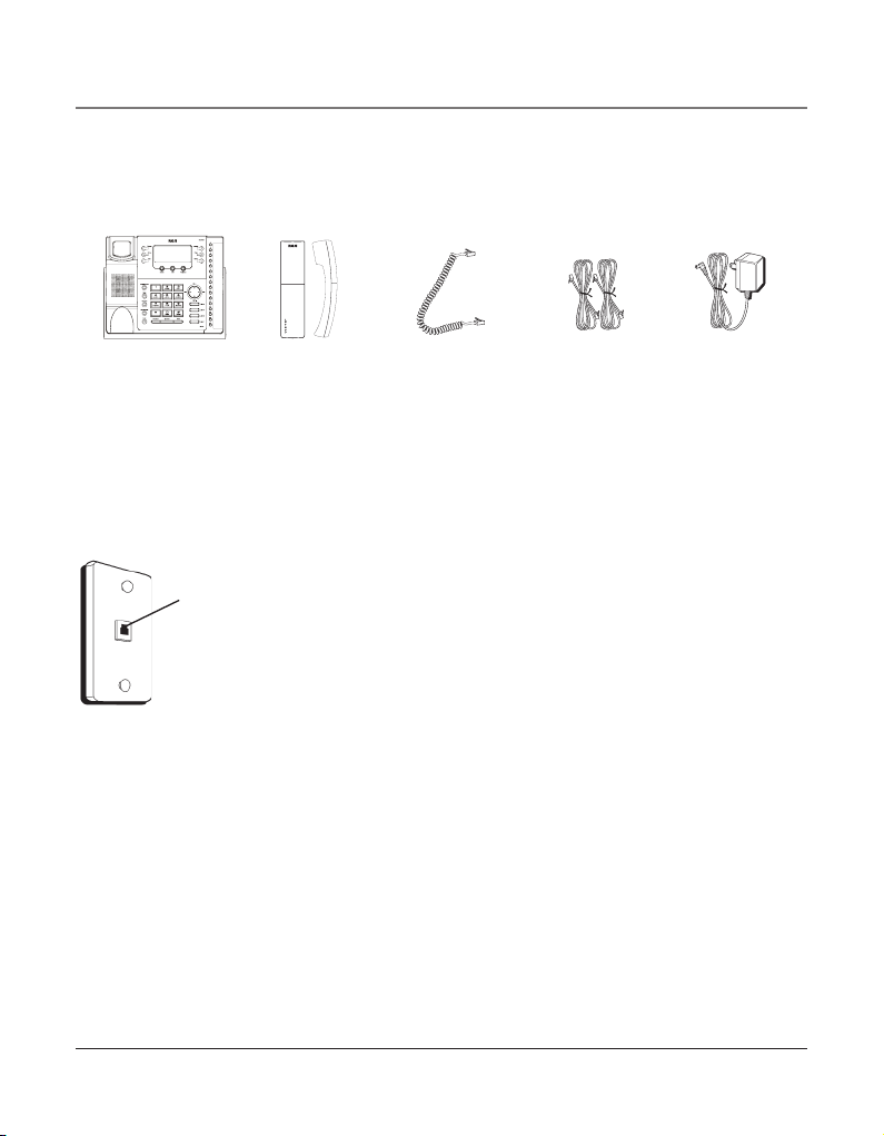
Parts Checklist
Make sure your package includes the following items:
Base
Handset Handset cord Line cords
AC power
adaptor
Telephone Jack Requirements
To use this phone, you will need an RJ11C (for a single line) or a RJ14C (for two lines) type
modular phone jack, which might look like the one pictured here, installed in your home
or office. If you don’t have either modular jack, call your local phone company to find out
how to get one installed.
Wall plate
Modular
telephone line
jack
VERY IMPORTANT: In order to achieve full system operation (i.e.
intercom, page, etc.), Line 1 must be connected and must be
common to all phones connected to the system. Only other 25423,
25424, 25425, 25413, 25414, 25415, 25403 and 25404 models are
compatible for full system operation. Connecting phones other
than the 25423, 25424, 25425, 25413, 25414, 25415, 25403 and
25404 to Line 1 may inhibit the intercom and paging operations.
For proper operation of intercom, page function, etc., DO NOT
connect a DSL modem to Line 1.
To transfer a call from one station to another, the two stations
should be connected to the same line.
8
Page 9
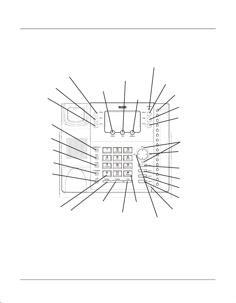
Base Layout
Menu
(button)
Exit
(button)
Redial/Format
(button)
Flash
(button)
Transfer
(button)
Conference
(button)
Hold
(button)
(button)
*
Privacy
(button)
Headset
(button)
Delete
(button)
Speaker
(button)
Dial
(button)
Mute
(button)
New Message
only applicable for
Model 25424
Sel/Save
(button)
#Pause
(button)
Connections & Setup
(indicator)
Intercom
(button)
Memory 1-16
(buttons)
Store
(button)
Volume pq
(buttons)
CID (button)
only applicable for
Model 25424
Line 3
(button)
Line 2
(button)
Line 1
(button)
Microphone
(for speakerphone)
DIRECTORY
(button)
Page
(button)
Line 4
(button)
9
Page 10

Connections & Setup
Important Installation Information
• Never install telephone wiring during a lightning storm.
• Never install telephone jacks in wet locations unless the jack is specifically designed for
wet locations.
• Never touch non-insulated telephone wires or terminals, unless the telephone line is
disconnected from the network.
• Use caution when installing or modifying telephone lines.
• Temporarily disconnect any equipment connected to the phone such as faxes, other
phones, or modems.
Important Installation Guidelines
• Install telephone near both a telephone (modular) jack and an electrical power outlet.
• Avoid sources of noise, such as a window by a busy street, and electrical noise, such as
motors, microwave ovens,
and fluorescent lighting.
• Avoid heat sources, such as heating air ducts, heating appliances, radiators, and direct
sunlight.
• Avoid areas of excessive moisture or extremely low temperature.
• Avoid dusty locations.
• Avoid other cordless telephones or personal computers.
CAUTION: Always disconnect all phone cords from the base unit before battery
installation or replacement.
10
Page 11

Connections & Setup
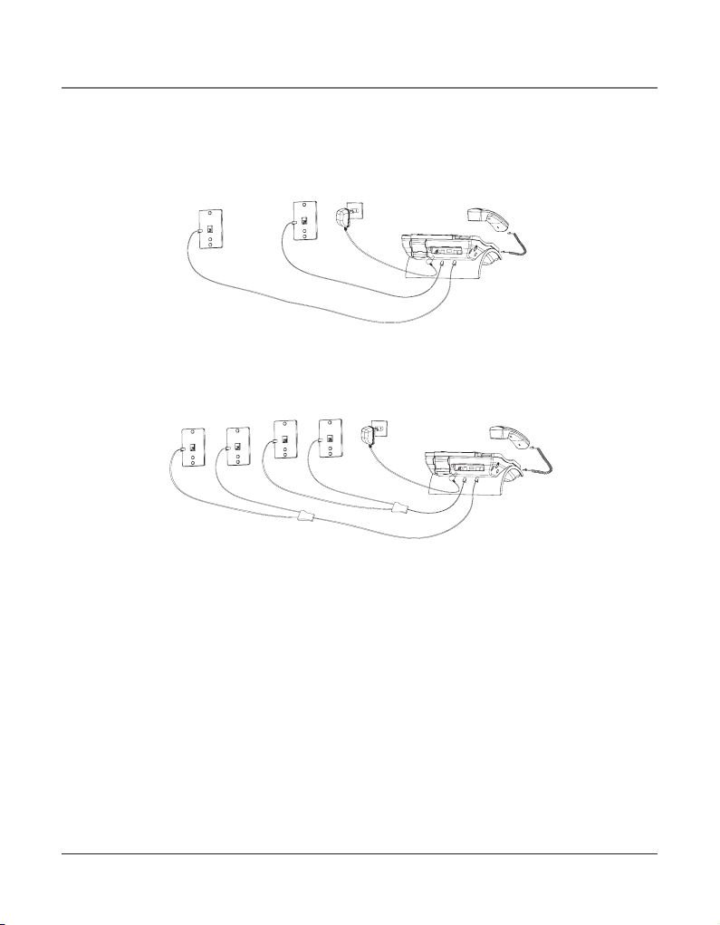
Installing the Phone
The phone may be connected to two 2-line (RJ14C) wall jacks or four single line (RJ11C)
wall jacks to accomodate all four lines.
IMPORTANT: Install batteries and connect the AC power supply to the base unit as
outlined in steps 1 through 3 below prior to connecting the telephone line cords to
insure for proper base station ID assignment.
1. Choose an area near an electrical outlet and telephone wall jack. Your phone should be
placed on a level surface, such as a table top or desk.
2. Install 4 AAA-size alkaline batteries (not included) for back up power in the event of a
power failure.
• Insert a flat bladed screw driver into the battery door
latch recess area and gently pry upward to release the
battery door from the base cabinet bottom.
• Insert the batteries as shown on the diagram inside the
battery compartment.
• Position the two (2) battery door tabs into the base
cabinet bottom slots and push downward until the door
latch “snaps” closed.
NOTE: If the low battery icon appears in the display, you need to replace the batteries. It
is important that you replace them as soon as possible to maintain unit operation when
electrical power is off. As a precaution, you may want to write down any stored information
you do not want erased.
IMPORTANT: If you are not going to use the telephone for more than 30 days, remove the
batteries because they can leak and damage the unit.
3. Plug the power supply cord into the power jack on the back of the base and the other
end into an electrical outlet.
CAUTION: To reduce risk of personal injury, fire, or damage use only the 5-2777 power
adaptor listed in the user’s guide. This power adaptor is intended to be correctly
orientated in a vertical or floor mount position.
11
Page 12
Connections & Setup
4. Connect the telephone line cords:
If you have two dual line wall jacks installed in your home or office, plug one end of
the straight telephone line cord tagged as “LINE 1+2” into the jack marked LINE 1 + 2
and one end of the other straight line cord into the other jack on the back of the base.
Plug the other end of each line cord into the dual-line wall jacks.
If you have four single-line wall jacks installed in your home or office, you must use
adaptors/couplers (not included) to combine the four single telephone lines into two
dual lines. The adaptor/coupler may look similar to the one pictured here and can be
purchased from your local telephone products retailer.
NOTE: To use four lines, you must have four telephone lines with unique telephone numbers.
If you only have one telephone line, this phone will still operate, but only as a single line
telephone.
Unit Initialization:
After you connect the power supply and Line 1 to the unit, the system automatically
searches for and sets up a phone ID.
NOTE:
• If the phone cannot find an ID, determine if there are too many phones connected to the
system. A maximum of 16 phones can be connected in the system.
• The Phone ID (01 to 16) is unique. When more than one phone using the same Phone ID is
detected, only one phone with that ID will be valid. The phone IDs for the other phone(s) is
automatically erased, and the phone(s) intercom indicators blink red and blue. You must use
the Menu options to select a new Phone ID for each phone.
12
Page 13

Connections & Setup
VERY IMPORTANT: In order to achieve full system operation (i.e. intercom, page, etc.), Line
1 must be connected and must be common to all phones connected to the system. Only
other 25413/14/15 models are compatible for full system operation. For proper operation of
intercom, page function, etc., DO NOT connect a DSL modem to Line 1.
• To set your own Phone ID, or change your phone ID, follow the steps in the Phone ID
section.
You may connect up to 16 RCA 25423, 25424 and/or 25425 phones to the system at
one time. Features like intercom, page and call transfer may be used among the units,
but Line 1 must be common for all 25423, 25424, or 25425 units for these features to
work properly. You may choose to share or privatize lines 2, 3 and 4.
5. Connect the handset cord:
Connect one end of the coiled handset cord to the jack on the side of the base and the
other end into the jack in the handset, and place the handset in the cradle.
6. Check for a dial tone:
Lift the handset and listen for a dial tone. If you hear a dial tone, the phone is
properly installed.
Data Port
This phone has a data port jack to connect an auxiliary phone device, such as a fax
machine, computer modem, answering machine, or even a cordless phone.
The data port switch on the back of the phone controls the data port jack so you can
choose Line 1, Line 2, Line 3, or Line 4.
Use the data port to hook up your fax machine, for example, and then set the data port
switch to Line 4 in order to receive faxes on the phone number for Line 4.
If you are talking to someone on Line 4 and want that person to fax something to you,
change the data port switch to Line 2 or Line 3, and give the person on-line the phone
number for Line 2 or Line 3. Your fax machine now can receive calls on Line 2, Line 3,
or Line 4.
IMPORTANT: Be sure to switch the fax machine back to the normal line when you are done
because outside callers who do not know that you have switched lines will not be able to
reach your fax machine if they dial the Line 4 number.
System Verification
Use the following procedures to test system configuration and identify possible line
connection errors. The phone must be connected to the power outlet, Line 1 must be
connected to the Line 1 + 2 jack, and the phone must have a phone ID.
VERY IMPORTANT: In order to achieve full system operation (i.e. intercom, page, etc.), Line
1 must be connected and common to all phones on the system. Only other 25423, 25424,
25425, 25413, 25414, 25415, 25403 and 25404 models are fully compatible.
13
Page 14

Programming the Telephone
Other System Phones
1. Press Line 1.
2. Look at all the other stations. If they all indicate line 1 is being used, the connection is
correct.
OR
1. Press the Intercom button. The display shows INTERCOM and ENTER CALLING PHONE ID.
2. Enter a phone ID by pressing an Intercom/Memo Log button (1-16). The display shows
the phone ID you entered. If the phone ID you entered is connected to the system, you
will hear a ring back tone (call through tone) at your phone. If the phone ID is not
connected to the system, you will hear an error tone. NO ANSWER shows in the display
and intercom is cancelled.
Programming the Telephone
When programming the phone, if at any time you wish to discontinue or stop
programming, press the “Exit” button. Also , whenever you have made a program selection
by pressing the Sel/Save button the display will shown “OK” for several seconds then will
return to the MAIN MENU prompt display.
Language
Set the display language to show messages in either English, Spanish, or French.
1. Press the Menu button while in standby mode. The cursor in the display points to
SET LANGUAGE.
2. Press the Sel/Save button.
3. Use the Vol (+ or -) buttons to scroll up or down to ENGLISH, ESPANOL, or FRANCAIS.
The default is English.
4. Press the Sel/Save button to save.
Volume
The ringer, speaker, and handset/headset volume is set independently with the
Vol (+ or -) buttons. There are 8 possible volume settings per mode. The volume indicator
scale is displayed during volume adjustment.
Ringer Volume
1. While the phone is on the hook, press the Vol (+ or -) button. The phone rings
according to the current setting.
2. Tap the Vol (+ or -) buttons to adjust the volume one level at a time. The phone stores
the setting after the last button press.
NOTE: To turn the ringer off, on, or change the ringing pattern, see Setting the Ringer Tone.
14
Page 15

Programming the Telephone
Speakerphone, Handset, and Headset Volume
While the phone is in use, during the desired mode, press the Vol (+ or -) buttons until you
reach a comfortable listening level. The phone stores the setting after the last button press.
Ringer Tone
The ringers for all four lines may be set independent of one another.
1. Press the Menu button while in standby mode.
2. Use the Vol (+ or -) buttons to scroll up or down to SET PHONE OPTIONS.
3. Press the Sel/Save button.
4. Use the Vol (+ or -) buttons to scroll up or down to SET RING TONE.
5. Press the Sel/Save button. The ringer tone settings for each of the four telephone lines
show in the display.
6. Use the Vol (+ or -) buttons to scroll up or down to select each ringer tone for Line 1. A
sample ringer tone is generated when you scroll to individual ringer tones. Choose from
eight different tones, or turn the ringer OFF.
NOTE: If you select OFF, the cursor automatically moves to the CID ON/OFF option. Use the Vol
(+ or -) buttons to scroll up or down to select CID ON or OFF. (ON allows the unit to detect and
display CID records for the corresponding telephone line. OFF disables the function for the
corresponding telephone.) Press the Sel/Save button.
NOTE: On Model 25423 you cannot select CID ON/OFF.
7. Press the Sel/Save button to save. The cursor automatically moves to Line 2.
8. Repeat steps 6 and 7 for each telephone line. After you select the ringer tone for
Line 4, press the Exit button.
NOTE: The line indicators flash for incoming calls even if the ringer is disabled.
Priority Line
The priority line (one of the four lines) has precedence over the other three lines. When you
pick up the handset or press the Speaker button, the unit automatically selects the priority
line first. If the priority line is in use by another party, the unit will select the next
available line.
1. Press the Menu button while in standby mode.
2. Use the Vol (+ or -) buttons to scroll up or down to SET PHONE OPTIONS.
3. Press the Sel/Save button.
4. Use the Vol (+ or -) buttons to scroll up or down to SET PRIORITY LINE.
5. Press the Sel/Save button.
6. Use the Vol (+ or -) buttons to scroll up or down to 1, 2, 3, or 4. The default is Line 1.
7. Press the Sel/Save button to save.
15
Page 16

Programming the Telephone
Delay Ring
Use this setting to delay the Central Office ring.
1. Press the Menu button while in standby mode.
2. Use the Vol (+ or -) buttons to scroll up or down to SET PHONE OPTIONS.
3. Press the Sel/Save button.
4. Use the Vol (+ or -) buttons to scroll up or down to SET DELAY RING.
5. Press the Sel/Save button.
6. Use the Vol (+ or -) buttons to scroll up or down to 0 ring up to 10 rings.
7. Press the Sel/Save button to save.
NOTE: The default Delay Ring is 0. If your system has a phone with the auto attendant ON, we
suggest that you set the Delay Ring to 2 rings. This allows the auto attendant to pick up the
incoming call before it rings in.
Phone ID
1. Press the Menu button while in standby mode.
2. Use the Vol (+ or -) buttons to scroll up or down to SET PHONE OPTIONS.
3. Press the Sel/Save button.
4. Use the Vol (+ or -) buttons to scroll up or down to SET PHONE ID.
5. Press the Sel/Save button.
6. Press the Sel/Save button again to automatically set the phone ID, or press any
memory button (1-16) to assign a phone ID.
NOTE: The Intercom indicator will flash red and blue if the ID is not programmed.
NOTE: The Phone ID (01-16) is unique. If you manually select a phone ID that belongs to
another unit on the system, NOT AVAILABLE shows in the display. Press Sel/Save or choose
another memory button.
NOTE: If the phone cannot find an ID, determine if there are too many phones connected to
the system. A maximum of 16 phones can be connected in the system at one time.
NOTE: You may press the Exit button at any time to exit , except during the ID search.
16
Page 17

Programming the Telephone
Phone Name
1. Press the Menu button while in standby mode.
2. Use the Vol (+ or -) buttons to scroll up or down to SET PHONE OPTIONS.
3. Press the Sel/Save button.
4. Use the Vol (+ or -) buttons to scroll up or down to SET PHONE NAME.
5. Press the Sel/Save button.
6. Use the touch-tone pad to enter the phonebook name (up to 8 characters). More than
one letter is stored in each of the number keys. For example, to enter “Lorraine,” press
the 5 key three times for the letter L. Press the 6 key three times for the letter O. Press
the 7 key three times for the first letter R. Press the 7 key three times for the second
letter R. Press the 2 key once for the letter A. Press the 4 key three times for the I. Press
the 6 key two times for the letter N. Press the 3 key twice for the letter E.
7. Press the Sel/Save button to save.
NOTE: The Phone Name and ID shows in the display when the phone is idle.
Intercom Auto Answer
For “hands-free” operation, the phone can be set to answer an intercom call by
automatically activating the speaker.
TIP: You may also use this feature for room monitoring.
1. Press the Menu button while in standby mode.
2. Use the Vol (+ or -) buttons to scroll up or down to SET PHONE OPTIONS.
3. Press the Sel/Save button.
4. Use the Vol (+ or -) buttons to scroll up or down to INTERCOM AUTO ANS.
5. Press the Sel/Save button.
6. Use the Vol (+ or -) buttons to scroll up or down to choose YES or NO.
7. Press the Sel/Save button to save.
17
Page 18

Programming the Telephone
Flash Time
1. Press the Menu button while in standby mode.
2. Use the Vol (+ or -) buttons to scroll up or down to SET PHONE OPTIONS.
3. Press the Sel/Save button.
4. Use the Vol (+ or -) buttons to scroll up or down to SET FLASH TIME.
5. Press the Sel/Save button.
6. Use the Vol (+ or -) buttons to scroll up or down through the flash time options.
The default setting is 600ms.
7. Press the Sel/Save button to save.
NOTE: You may press the Exit button at any time to exit.
Call Alert Tone
Turn on the Call Alert to hear a tone for incoming calls while you are on the telephone. This
function notifies you that there is a incoming call while you are using the phone. If you do
not want this tone to disturb your conversation, you can set it to OFF.
1. Press the Menu button while in standby mode.
2. Use the Vol (+ or -) buttons to scroll up or down to SET PHONE OPTIONS.
3. Press the Sel/Save button.
4. Use the Vol (+ or -) buttons to scroll up or down to CALL ALERT TONE.
5. Press the Sel/Save button.
6. Use the Vol (+ or -) buttons to scroll up or down to ON or OFF.
7. Press the Sel/Save button to save. The cursor automatically moves to Line 2.
8. Repeat steps 6 and 7 for each telephone line. After you select a tone for Line 4, press
the Exit button.
No Unknown/Blocked
This option allows you to decide whether the unknown or blocked caller ID calls are saved
or not. If you select YES, the unknown or blocked calls will be saved.
1. Press the Menu button while in standby mode.
2. Use the Vol (+ or -) buttons to scroll up or down to SET PHONE OPTIONS.
3. Press the Sel/Save button.
4. Use the Vol (+ or -) buttons to scroll up or down to NO UNKNOWN/BLOCKED.
5. Press the Sel/Save button.
6. Use the Vol (+ or -) buttons to scroll up or down to YES or NO. The default is YES.
18
Page 19

Programming the Telephone
7. Press the Sel/Save button to save.
NOTE: Not applicable to Model 25423.
Display Contrast
Adjust the display contrast to one of four contrast levels.
1. Press the Menu button while in standby mode.
2. Use the Vol (+ or -) buttons to scroll up or down to SET LCD CONTRAST.
3. Press the Sel/Save button. The MIN and MAX contrast scale shows on the display.
4. Use the DIR or CID (left/right) buttons to adjust the contrast. The display instantly
adjusts with each press of the button.
5. Press the Sel/Save button to save the desired contrast level.
Local Area Code
1. Press the Menu button while in standby mode.
2. Use the Vol (+ or -) buttons to scroll up or down to SET AREA CODE.
3. Press the Sel/Save button.
4. Use the Vol (+ or -) buttons to scroll up or down to LOCAL AREA CODE.
5. Press the Sel/Save button. Enter Number shows in the display.
6. Use the touch tone pad on your phone to enter your local area code.
7. Press the Sel/Save button to save.
NOTE: If you make a mistake, press Delete to erase all digits.
NOTE: Not applicable to Model 25423.
Regional Area Codes
Depending on your location, you may need to set up to six regional area codes. Setting
Regional Area Codes helps the phone determine the number format to display when a
valid CID record is received. Call records matching any of the set regional area codes are
displayed as 10 digits.
NOTE: If the CID telephone number does not display correctly, you may not be able to dial
back the number from the Caller ID menu.
You may need to set regional area codes if you reside in an area which:
• uses multiple area codes
• uses overlapping area codes
• requires 10-digit dialing.
19
Page 20

Programming the Telephone
1. Press the Menu button while in standby mode.
2. Use the Vol (+ or -) buttons to scroll up or down to SET AREA CODE.
3. Press the Sel/Save button.
4. Use the Vol (+ or -) buttons to scroll up or down to REGIONAL AREA CODES.
5. Press the Sel/Save button. All six regional area code fields and Enter Number show in
the display.
6. Use the touch tone pad on your phone to enter up to six regional area codes.
7. Press the Sel/Save button to save.
NOTE: If you make a mistake, press the Delete button to erase all digits.
NOTE: Not applicable to Model 25423.
Manually Setting the Time and Date
The time and date is automatically set when you receive the first CID call. To manually
reset the time and date, follow the steps below.
1. Press the Menu button while in standby mode.
2. Use the Vol (+ or -) buttons to scroll up or down to SET TIME & DATE.
3. Press the Sel/Save button.
4. Use the Vol (+ or -) buttons to scroll up or down to SET CLOCK.
5. Press the Sel/Save button, and the cursor moves to the hour field.
6. Use the Vol (+ or -) buttons to scroll up or down to select the hour.
NOTE: AM or PM will be set accordingly with selected hour.
7. Press the Sel/Save button, and the cursor moves to the minute field.
8. Use the Vol (+ or -) buttons to scroll up or down to select the minutes.
9. Press the Sel/Save button, and the cursor moves to the month field.
10. Use the Vol (+ or -) buttons to scroll up or down to select the month.
11. Press the Sel/Save button, and the cursor moves to the date field.
12. Use the Vol (+ or -) buttons to scroll up or down to select the date.
13. Press the Sel/Save button, and the cursor moves to the day field.
14. Use the Vol (+ or -) buttons to scroll up or down to select the day.
15. Press the Sel/Save button, and the cursor moves back to the hour field.
16. Press the Exit button.
NOTE: You may press Exit at any step in the process. It is not necessary to re-program the
complete time and date if you only want to adjust certain fields (i.e.; hour only).
20
Page 21

Basic Operation
Hour Format
You may set this phone to a 12 or 24-hour format. The default is 12-hour format.
1. Press the Menu button while in standby mode.
2. Use the Vol (+ or -) buttons to scroll up or down to SET TIME & DATE.
3. Press the Sel/Save button.
4. Use the Vol (+ or -) buttons to scroll up or down to SET HOUR FORMAT.
5. Press the Sel/Save button.
6. Use the Vol (+ or -) buttons to scroll up or down to select 12-HOUR or 24-HOUR.
7. Press the Sel/Save button to save.
Restoring the Default Settings
This feature allows you to reset the menu to the original factory default settings.
1. Press the Menu button while in standby mode.
2. Use the Vol (+ or -) buttons to scroll up or down to RESTORE TO DEFAULTS.
3. Press the Sel/Save button.
4. Use the Vol (+ or -) buttons to scroll up or down to YES or NO.
5. Press the Sel/Save button to save.
Basic Operation
Your phone provides the convenience of accessing four separate telephone lines, each
obtained from the telephone company and each having its own phone number. This is
generally applicable to small offices. It provides for 16 telephones (or stations) to share
multiple lines. Each station is interconnected to all others by an intercom.
Making Calls with the Handset
1. Pick up the handset and the phone automatically selects the priority line. If the
priority line is occupied, it selects an open line.
OR
Pick up the handset and press a Line button to select a line.
2. Wait for a dial tone, then dial a phone number.
3. Hang up the handset when finished.
21
Page 22

Basic Operation
Making Calls with the Speakerphone
1. Press the Speaker button and the phone automatically selects the priority line. If the
priority line is occupied, it selects an open line.
OR
Press a Line button to select a line.
2. Wait for a dial tone then dial a phone number.
3. Press Speaker button when finished.
NOTE: Only one-way conversation is possible in speakerphone mode. When you are speaking,
you are transmitting. When you are listening, you are receiving. You can’t do both at
the same time. The phone will automatically switch between transmitting and receiving
depending on the level of the voice or the room noise picked up by the speakerphone mic.
NOTE: If a line goes off-hook, the call timer counts time until all the lines go on hook. The
timer serves for 4 lines.
Making Calls with the Optional Headset
1. Connect the headset plug into the Headset jack on the left side of the base.
2. Adjust the headset to rest comfortably on top of your head and over your ear.
3. Move the microphone to approximately 2 to 3 inches from your mouth.
4. Press the Headset button and the phone automatically selects the priority line. If the
priority line is occupied, it selects an open line.
5. Wait for a dial tone, then dial a phone number.
6. Press Headset when finished.
CAUTION: Use only the Thomson Inc. 5-2425 headset that is compatible with this unit.
NOTE: If the headset is not connected (or if not completely inserted into headset jack), an
error tone is heard when the Headset button is pressed and the display will show Error for
several seconds.
Pre-dialing
1. With the phone idle and the handset on the cradle, manually enter the telephone
number. The telephone number shows in the display.
2. Press the Dial or Speaker button, or lift the handset to take a line, and the
telephone number is automatically dialed.
22
Page 23

Basic Operation
Answering Calls
If you receive a call on the priority line,
1. Pick up the handset (handset mode), OR
2. Press the Speaker button (speakerphone mode), OR
3. Press the Headset button (headset mode).
4. When finished, hang up the handset, or press the Speaker button or press the
Headset button.
If you receive a call on a line other than the priority line,
1. Pick up the handset and press the corresponding line button (handset mode), OR
2. Press the Speaker button and press the corresponding line button (speakerphone mode),
OR
3. Press the corresponding line button, and then press the Headset button
(headset mode).
4. When finished, hang up the handset, or press the Speaker button, or press the
Headset button.
NOTE: Whether you are making or receiving a call, the caller is disconnected if you press
another line without putting the call on hold first.
Switching Between the Speakerphone, Handset, and Headset
To switch to the speakerphone, press Speaker. The speakerphone indicator turns on.
Put handset back in cradle.
To switch to the handset, pick up the handset. The speakerphone or headset turns off.
To switch to the headset, press the Headset button to enable the headset, and the
headset indicator turns on. Hang up the handset.
Mute
To have a private, off-line conversation, use the Mute feature. The party on the other
end of the line cannot hear you, but you can still hear them.
1. Press Mute to activate the mute feature. The mute indicator turns on.
2. Press Mute again to turn it off.
NOTE: Switching from speakerphone to handset cancels mute.
23
Page 24

Basic Operation
Do Not Disturb
This feature is set at individual telephones to disable (silence) an incoming ring signal,
intercom ring, or page. When there is an incoming call or an intercom call, the status
indicators function as normal but the phone will not ring.
1. When the unit is idle, press the Privacy button. The Privacy indicator flashes and the
last setting is displayed.
2. Use the Vol (+ or -) buttons to scroll up or down to select the duration. You may choose
from 15 minutes, 30 minutes, 45 minutes, 1 hour, or 2 hours and increase the duration
by 1 hour intervals up to 24 hours.
3. Press the Sel/Save button to confirm. The indicator blinks and the display shows how
long the ringer will be disabled.
4. To cancel, press Privacy again or hang up the handset.
NOTE: If Intercom Auto Answer is turned ON, the unit automatically answers the intercom
call even if the Do Not Disturb function is activated.
Hold
Placing a Call on Hold
Press the Hold button to put the line in use on hold. The line indicator for the line on hold
flashes blue. The phone emits a beep every 30 seconds as a reminder. At the other stations,
the indicator blinks red but no beep is heard.
NOTE: If you put a call on Hold while in Privacy mode, no one but you can access the line on
hold. Anyone trying to access the line receives an error tone.
Releasing a Call from Hold
Press the Hold button or the corresponding Line button to release hold.
NOTE: If you want to change modes, lift the handset to switch to the handset, or press the
Headset button to use the headset.
NOTE: The call on hold can be picked up at any station using this procedure.
Flash
Use the Flash button to activate custom calling services such as call waiting or call
forwarding, which are available through your local phone company.
24
Page 25

Basic Operation
Redial
1. Pick up the handset (handset mode), or press the Speaker button (speakerphone mode),
or press the Headset button (headset mode) and the priority line is
automatically selected,
OR
Press a line button to select other line.
2. Press the Redial/Format button
NOTE: The redial function will not operate if the number to be redialed contains more than
32 digits. If the number is longer than that, you will hear an error tone.
Reviewing the Redial Numbers
Your phone records up to six previously dialed phone numbers.
1. When the phone is idle, press the Redial/Format button.
2. Use the Vol (+ or -) buttons to scroll up or down to view the last six previously dialed
numbers.
3. While the preferred number is displayed, pick up the handset or press the Speaker, Dial,
or a line button to dial the phone number.
NOTE: If you do not select a line button, the line is automatically seized and the number is
dialed accordingly.
Transferring a Call to Another Station
1. With the caller on the line, press the Transfer button.
2. Press the Intercom/Memory Log button (1-16) for the station you want to transfer the
call to. The line’s indicator blinks purple until the party picks up the transferred call.
Once the call is picked up, the indicator stays red. The indicator on the receiving party’s
line rapidly flashes red and rings during call transfer.
• If the transferred call is not picked up at the other station within 45 seconds. The
transfer cancels, the line is put on hold, and the line indicator flashes blue.
• If the party at the other station doesn’t pick up the transferred call, and you want to
attempt to transfer to another station, press the line button and repeat the transfer
process from step 1.
25
Page 26

Basic Operation
Receiving a Transferred Call from Another Station
If a call is transferred to your station, the line indicator flashes red. To answer the call, press
that line button.
If you are on the line when a call is transferred to you, you will hear beeps to alert you
of the incoming call. Put your current call on hold by pressing Hold, and then pick up the
incoming call by pressing the corresponding line button.
NOTE: During the transfer, the only two stations that can access the line are: a) the
transferring station, or; b) the station receiving the transfer.
VERY IMPORTANT: To transfer a call from one station to another, the two stations should be
connected to the same line.
Message Waiting
Provide your phone company offers voice messaging service and you subscribe to it, the
New Message indicator flashes when the phone is not in use to indicate there is a message
waiting. Also, from the display, you can find which line has message waiting. The indicator
stops flashing after the message is reviewed.
NOTE: Not applicable to Model 25423.
Privacy
While in use, a line can be secured so that no one else can listen to the conversation. This
feature only applies to 25423, 25424, 25425, 25413, 25414, 25415, 25403 and 25404
phones. However, other phone which are not compatible with these models can still access
the line.
Providing Privacy
At any time during a conversation, you can use the privacy feature to secure the line.
1. While on a line, press the Privacy button. The indicator turns on.
2. To cancel, press Privacy again or hang up.
NOTE: If you put a call on hold while in privacy mode, no one but you can access the line on
hold.
Conference Calls
This feature allows you to have a 3-way conversation using any combination of 2 lines.
To connect and conference
1. To make a call, press the line you want and dial the telephone number. If you already
have someone on the line, skip to step 2.
2. Press the Hold button to place the call on hold.
26
Page 27

Intercom Calls
3. Press another line button and dial the telephone number of the party you want to
conference with.
4. Press the Conference button.
5. Speak to both parties.
NOTE: If you have more than one line on hold, and you want to have a conference call, you
must first select the line on which you want to conference.
To disconnect one party:
Press the line button for the person you want to continue speaking with, and the other
party is automatically disconnected.
To disconnect both parties:
Hang up the handset, or press the Speaker or Headset button.
NOTE: If you press the Hold button to put them on hold first, you may then disconnect from
each party individually.
Intercom Calls
One-Touch Intercom
NOTE: If the Intercom indicator is turned on (solid red), the intercom is in use. You must wait
until the indicator turns off before making an intercom call.
1. Press the Intercom/Memory Log button (1-16) for the station you want to
intercom with. The Speaker turns on.
Alternately, you may press the Intercom button, then press the Intercom/Memory Log
button (1-16) for the stations you want to intercom with. The speakerphone
automatically turns on.
NOTE: If you want to switch to the handset, pick it up and continue speaking. To switch to
the headset press the Headset button.
NOTE: The handset, headset, or speakerphone cannot be active when an intercom call is
initiated (the handset should be on the cradle and the speakerphone and headset turned
OFF.)
NOTE: To abort intercom call, press Speaker button.
2. To end the intercom call, hang up.
NOTE: If the receiving station does not answer within 45 seconds, the intercom call is
cancelled. You will hear an error tone and NO ANSWER shows in the display. NOTE: If the
intercom is in use. You will hear an error tone and ERROR INHIBITED shows in the display.
27
Page 28

Intercom Calls
Answering an Intercom Call
When you receive an Intercom call, the Intercom indicator flashes red, and the display
shows the caller’s name and phone ID.
NOTE: If you want to answer with the speakerphone, press the Intercom or Speaker button. If
you want to answer by headset, press the Headset button (the headset must be connected).
To answer by handset, lift the handset.
NOTE: Press Speaker or lift the handset to automatically select a party. If you receive an
incoming call and intercom call at the same time the unit automatically selects the ringing
line.
Intercom Hold
1. Make an intercom call or answer an intercom call.
2. Press the Hold button. The Intercom indicator flashes blue.
NOTE:
• When the intercom is on hold, you may not receive another intercom.
• If the other party terminates intercom, intercom hold is also released.
Intercom Conference Calls
This feature allows you to have a 3-way conversation using the intercom feature and an
open line.
1. Place a call or make an intercom call.
2. Press the Hold button.
3. Place a call on another line or make an intercom call.
4. Press the Conference button.
5. Speak to both parties.
NOTE: If you have more than one party on hold (telephone line or intercom), you must select
the line for the party you want to conference with.
To disconnect one party:
Press the line or intercom button for the person you want to continue speaking with, and
the other party is automatically disconnected.
To disconnect both parties:
Hang up the handset, or press the Speaker button.
NOTE: If you press the Hold button to put them on hold first, you may then disconnect from
each party individually.
28
Page 29

Caller ID
Paging All Stations
1. Lift the handset.
2. Press the Page button and listen for the beep. The other stations not in use
automatically activate their speakerphones and receive your page.
3. Speak into the handset. You have 30 seconds to page in this mode. After 30 seconds,
the page is cancelled.
4. When finished, hang up the handset.
NOTE: You will not receive a page when Do Not Disturb is turned on.
NOTE: Paging can be done with optional headset. plug in headset, press Headset button, the
press Page button.
Caller ID
Note: The Caller ID section of this user’s guide is not applicable to Model 25423.
Summary Screen
The summary screen shows the current time, current date, number of CID records to be
reviewed and total number of records saved to CID memory. It is displayed until any
button is pressed. Within 60 seconds of receiving a new call, the new caller information is
displayed.
Phone ID
Battery indicator
Time and date
Name of phone
CID records
waiting
to be reviewed
Number of records in CID
memory
Receiving and Storing CID Records
This unit receives and displays information transmitted by your local phone company. This
information can include the phone number, date and time; or the name, phone number,
date and time. The unit can store up to 99 calls for later review. When the memory is full,
a new call automatically replaces the oldest call in memory. NEW appears in the display
for calls received that have not been reviewed. The line number for the call received is also
displayed.
29
Page 30

Caller ID
Reviewing CID Records
• Press the CID button , and then use the Vol (+ or -) buttons
to scroll through the call records.
• When you scroll to the start/end of the list, START/END
appears in the display.
Saving a CID Record to the Intercom/Memory Log or to Phone Book Memory
1. While a name and telephone number shows in the
display, if you need to edit the information, press the Sel/Save button and follow the
steps for Storing a Name and Number in Memory.
2. If you do not need to edit the name or number, press the Store button.
3. To store data in the Phone Book Directory, press the DIR button,
OR
To store data in the Intercom/Memory Log, press a memory log button (1-16).
Deleting a CID Record
To delete the record shown in the display, press the Delete button once.
Deleting All Call Records
This feature allows you to clear all CID records at once.
1. While viewing a CID record, press and hold the Delete button. PRESS DELETE AGAIN
CLEAR ALL CALLER ID shows in the display.
2. Press the Delete button again to confirm.
Dialing Back
When reviewing CID records, you can dial back the numbers
showing on the display by pressing the Dial button.
If You Programmed Your Local Area Code
1. Press the CID button , and then use the Vol (+ or -) buttons to display the number you
want to dial.
2. If you see a number with 7 digits (i.e.555-1234), then the call was received from within
your area code. However, this does not guarantee the call is a local call. If you see a
number with 11 digits (i.e.1-234-555-1234), then the call received was not from your
area code.
3. To adjust the phone number format, use the Redial/Format button. For instance, a 7digit local number sometimes cannot be dialed because it requires a 10-digit or 11-digit
format. Use the Redial/Format button to scroll through 7, 10 and 11-digit numbers.
30
Page 31

Memory
7-digits: 7-digit telephone number (i.e.555-5555)
10-digits: 3-digit area code +7-digit telephone number (i.e.425-555-5555)
11-digits: long distance code 1 +3-digit area code +7-digit telephone number
(i.e. 1-425-555-5555)
4. To dial the displayed number, select a line or press Dial again.
If You Did Not Program Your Local Area Code
1. Press the CID button , and then use the Vol (+ or -) buttons to display the number you
want to dial. You will only see 10-digit numbers (i.e.234-555-1234).
2. Press Dial to dial back. You may adjust the number format by pressing the
Redial/Format button before dialing.
Call Waiting Caller ID
This feature allows you to see who is calling when you hear the call waiting beep. The caller
identification information appears in the display after you hear the tone.
• Press the Flash button to put the person to whom you’re talking on hold and answer
the incoming call.
IMPORTANT: To use all the features of this unit, you must subscribe to either the standard
Name/Number Caller ID Service or Caller ID with Call Waiting Service. To know who is calling
while you are on the phone, you must subscribe to Caller ID with Call Waiting Service.
Memory Log and Phone Book (Directory) Memory
You may store data in the Phone Book Directory (up to 94 memories) or an Intercom/
Memory Log (16 buttons located to the right of the number pad on the base). The Phone
Book and each Intercom/Memory Log stores up to 21 characters and 32 digits.
Storing a Number and Name in Memory
NOTE: To cancel the storing procedure at any time, press Exit.
1. Press the Store button. ENTER NUMBER is displayed.
2. Use the touch tone pad on your telephone to enter the telephone number you want to
store. The numbers you enter show in the display.
NOTE: If you make a mistake, use the DIR or CID buttons (left/right) to move the cursor to
the incorrect digit, and press the Delete button to delete.
3. Press Sel/Save. ENTER NAME is displayed.
31
Page 32

Memory
4. Use the touch-tone pad to enter a name (up to 21 characters). More than one letter
is stored in each of the number keys. For example, to enter Bill Smith, press the 2 key
twice for the letter B. Press the 4 key 3 times for the letter I. Press the 5 key 3 times for
the letter L. Press the 5 key 3 times for the second letter L, and press the 1 key to insert
a space between the first and last name. Press the 7 key 4 times for the letter S; press
the 6 key once for the letter M; press the 4 key 3 times for the letter I; press the 8 key
for the letter T; press the 4 key twice for the letter H.
NOTE: If you make a mistake, use the DIR or CID buttons (left/right) to move the cursor to
the incorrect digit, and press the Delete button to delete.
5. Press Store button. ENTER LOCATION is displayed.
6. Enter memory location:
Press the DIR button to save the record in the Phone Book memory,
OR
Press a Intercom/Memory Log button (1-16) to save the record in that memory
location.
NOTE: If there is a record stored in selected memory location “OVERWRITE?” shows in the
display. Press Store to confirm overwrite or press the Exit button, then select a new location.
7. Repeat steps 1-6 for any additional names and numbers you want to store, up to 94, in
phone book memory.
NOTE: The storage procedure automatically cancels after 30 seconds if no keys are pressed.
Reviewing Phone Book (Directory) Memory
1. Press the DIR button. The first memory in the phone book is displayed (memories are
stored in alphabetical order).
2. Use the Vol (+ or -) buttons to scroll up or down through the phone book
memories, or use the touch tone pad on your phone to enter the corresponding
letters for the memory you want to review. For example, press the 5 key to display
phone book memories that start with the letter J. Press the 5 key twice to go to
memories starting with the letter K.
3. Press the Exit button when you are finished reviewing memories.
Reviewing the Intercom/Memory Log (memory location)
1. Press the DIR button.
2. Press the Intercom/Memory Log button (1-16).
3. Press the Exit button when you are finished reviewing memories.
32
Page 33

Memory
Editing a Name or Number Stored in Phone Book (Directory) Memory
1. Press the DIR button.
2. Use the Vol (+ or -) buttons to scroll up or down to the desired memory record.
3. Press the Sel/Save button and edit the content according to the steps in the
Storing a Name and Number in Memory section.
Editing a Name or Number Stored in the Intercom/Memory Log
(Memory Location)
1. Press the DIR button.
2. Press the Intercom/Memory Log button (1-16).
3. Press the Sel/Save button and edit the content according to the steps in the
Storing a Name and Number in Memory section.
Storing the Last Number Dialed
1. When the phone is idle, press the Redial/Format button.
2. Use the Vol (+ or -) buttons to scroll up or down to view the last six previously
dialed numbers.
3. While viewing the desired number, press the Sel/Save button twice.
4. Add the name as explained in the Storing A Name and Number in Memory section.
5. Press the Store button. ENTER LOCATION shows in the display.
6. Press the DIR button to store the redial number in the Phone Book memory or press an
Intercom/Memory Log button (1-16) to store the redial number in that memory
location.
Storing a Pause in Memory
Press the #Pause button twice to insert a pause in the dialing sequence of a stored
telephone number when a pause is needed (for example, when you must dial a 9 to get an
outside line or when you must enter codes to access your bank’s information line).
Dialing a Stored Number
1. Pick up the handset, or press Speaker to automatically select a line. Or press the line
you want to use.
2. Wait for a dial tone.
3. Press the Intercom/Memory Log button (1-16) for the person you want to call.
The number automatically dials.
OR
1. Press the DIR button.
33
Page 34

Memory
2. Use the Vol (+ or -) buttons to scroll up or down through the phone book memories, or
use the touch tone pad to enter the corresponding letters for the memory you want to
review. For example, press the 5 key to display phone book memories that start with the
letter J. Press the 5 key twice to go to memories starting with the
letter K.
3. Press the Dial button. The number automatically dials.
Memory Delete/Clear
To delete a Phone Book memory:
1. Press the DIR button.
2. Use the Vol (+ or -) buttons to scroll up or down to the memory you want to delete.
3. Press the Delete button to delete. DELETE -DELETE AGAIN shows in the display.
4. Press the Delete button again to confirm.
To delete an Intercom/Memory Log:
1. Press the DIR button.
2. Press the corresponding button (1-16) for the Intercom/Memory Log you want to
delete.
3. Press the Delete button to delete, DELETE -DELETE AGAIN shows in the display.
4. Press the Delete button again to confirm.
NOTE: Press the Exit button to cancel the “delete” function.
Clear All Memories
1. Press the Menu button while in standby mode.
2. Use the Vol (+ or -) buttons to scroll up or down to SET PHONE OPTIONS.
3. Press the Sel/Save button.
4. Use the Vol (+ or -) buttons to scroll up or down to CLEAR ALL MEMORIES.
5. Press the Sel/Save button.
6. Use the Vol (+ or -) buttons to scroll up or down to Yes or No, No is the default.
7. Press the Sel/Save button to confirm.
NOTE: If you select YES, all the directory memories and direct access memories are cleared.
34
Page 35

Memory
Chain Dialing
This process allows you to dial a succession of stored numbers from separate memory
locations. This is useful when you must dial several sequences of numbers, such as with
frequent calls via a telephone company long distance provider.
For example Memory location
Local access number of long distance company 6
Authorization code (ID) 7
Long distance phone number 8
1. Press the line you want.
2. Press memory location 6.
3. Press memory location 7.
4. Press memory location 8.
Display Messages
The following special messages indicate the status of a message or the unit:
00 TOTAL CALLS
UNKNOWN CALLER The incoming call does not have Caller ID service or their
BLOCKED CALL
INCOMPLETE DATA
NO DATA
START/END
Battery power level is low.
The Caller ID memory log is empty.
service area is not linked to yours. If UNKNOWN CALLER
appears along with a calling number, the name information for
that number was not available.
The caller is registered as “Private Number ”and their Caller ID
information is withheld.
Caller information has been interrupted or corrupted during
transmission.
No Caller ID signal has been detected, or Caller ID service has not
been activated.
You are at the beginning or the end of the Caller ID memory log.
Operation By Battery
If the power cord is not plugged into the unit, and the battery is available, the unit enters
Battery Operation Mode. In this mode, the unit fully supports all operational features,
except the intercom call function and cordless handset.
NOTE: Under battery operation mode, the RF module (optional for use with cordless handset)
is not supported.
35
Page 36

Troubleshooting Guide
Operation without Power
If the power cord is not plugged into the unit and no battery is installed, the unit enters
into No Power Operation mode. in this mode, the user may:
1) use the handset to manually make a call on line 1 only,
2) answer a call on line 1 with the handset.
Cordless Phone Option
It is possible to enhance your phone to a cordless feature with the additional purchase of
the H5401 accessory handset and module. The H5401 is packaged with an RF module, when
the module is properly inserted into the back of the 25423/24 base, the antenna icon on
the display will illuminate.
Troubleshooting Guide
No dial tone
• Check or repeat installation steps:
• Make sure the telephone line cords are connected to the phone and the wall jack. Make
sure the line cords are not damaged.
• Make sure the hook switch pops up when the handset is lifted.
• Check the Speaker button. Make sure the indicator is off.
• Disconnect the phone from the wall jack and connect another phone to the same jack.
If there is no dial tone in the second phone, the problem might be your wiring
or local service.
You cannot be heard by the other party.
• Make sure the handset or headset cord is inserted properly and securely.
• Make sure the Mute feature is not turned on.
Phone does not ring.
• Make sure the ringer is turned on.
• Make sure the Do Not Disturb feature is not activated.
• You may have too many extension phones on your line. Try unplugging some phones.
• See solutions for “No dial tone.”
Incoming voice too low or none at all.
• Check volume setting.
36
Page 37

Troubleshooting Guide
Memory dialing doesn’t work
• Did you program the memory location keys correctly?
• Did you follow proper dialing sequence?
Battery icon is blank or shows only one bar
• The 4 “AAA” batteries need replacing or are improperly installed or not installed at all.
Intercom does not function correctly
• Make sure line 1 is connected properly and common to all phones on the system.
• Make sure all phone ID’s (station numbers) involved have been assigned.
Transfer does not function correctly
• Make sure receiver phones (stations) have same line connected.
Intercom indicator turns red and blue alternately
• The station address needs to be re-assigned due to a duplicate station address in the
system. See “Changing the Phone ID (Station Address)”.
General Product Care
To keep your telephone working and looking good, follow these guidelines:
• Avoid putting the phone near heating appliances and devices that generate electrical
noise (for example, motors or fluorescent lamps).
• DO NOT expose to direct sunlight or moisture.
• Avoid dropping the handset, as well as other rough treatment to the phone.
• Clean the phone with a soft cloth.
• Never use a strong cleaning agent or abrasive powder because this will damage
the finish.
• Retain the original packaging in case you need to ship the phone at a later date.
37
Page 38

Warranty Assistance
Warranty Assistance
If trouble is experienced with this equipment, for warranty information, please contact
customer service at 1-800-448-0329. If the equipment is causing harm to the telephone
network, the telephone company may require that you disconnect the equipment until the
problem is resolved.
Any unauthorized repairs, changes or modifications not expressly approved by Thomson Inc.
could void the user’s authority to operate this product. For instructions on how to obtain
a replacement unit, refer to the warranty included in this guide or call customer service at
1-800-448-0329.
Or refer inquiries to:
Thomson Inc.
Manager, Consumer Relations
P O Box 1976
Indianapolis, IN 46206
Attach your sales receipt to this booklet for future reference or jot down the date this
product was purchased or received as a gift. This information will be valuable if service
should be required during the warranty period.
Purchase date
Name of store
38
Page 39

Accessory Information
Accessory Information
AC power adaptor
5-2777
To place order, have your Visa, MasterCard, or Discover Card ready and call toll-free
1-800-338-0376.
A shipping and handling fee will be charged upon ordering.
We are required by law to collect appropriate sales tax for each individual state, country,
and locality to which the merchandise is being sent.
Items are subject to availability. *Prices are subject to change without notice.
39
Page 40

Warranty
Limited Warranty
What your warranty covers:
• Defects in materials or workmanship.
For how long after your purchase:
• Two years, from date of purchase. (The warranty period for rental units begins with the
first rental or 45 days from date of shipment to the rental firm, whichever comes first.)
What we will do:
• Provide you with a new or, at our option, a refurbished unit. The exchange unit is under
warranty for the remainder of the original product’s warranty period.
How you get service:
• Properly pack your unit. Include any cables, etc., which were originally provided with
the product. We recommend using the original carton and packing materials.
• ”Proof of purchase in the form of a bill of sale or receipted invoice which is evidence
that the product is within the warranty period, must be presented to obtain warranty
service.” For rental firms, proof of first rental is also required. Also print your name and
address and a description of the defect. Send via standard UPS or its equivalent to:
Thomson, Inc.
11721 B Alameda Ave.
Socorro, Texas 79927
• Pay any charges billed to you by the Exchange Center for service not covered by the
warranty.
• Insure your shipment for loss or damage. Thomson, Inc. accepts no liability in case of
damage or loss.
• A new or refurbished unit will be shipped to you freight prepaid.
What your warranty does not cover:
• Customer instruction. (Your Owner’s Manual provides information regarding operating
instructions and user controls. Any additional information, should be obtained from
your dealer.)
• Installation and setup service adjustments.
• Batteries.
• Damage from misuse or neglect.
• Products which have been modified or incorporated into other products.
• Products purchased or serviced outside the USA.
• Acts of nature, such as but not limited to lightning damage.
40
Page 41

Warranty
Product Registration:
• Please complete and mail the Product Registration Card packed with your unit. It will
make it easier to contact you should it ever be necessary. The return of the card is not
required for warranty coverage.
Limitation of Warranty:
• THE WARRANTY STATED ABOVE IS THE ONLY WARRANTY APPLICABLE TO THIS
PRODUCT. ALL OTHER WARRANTIES, EXPRESS OR IMPLIED (INCLUDING ALL IMPLIED
WARRANTIES OF MERCHANTABILITY OR FITNESS FOR A PARTICULAR
PURPOSE) ARE HEREBY DISCLAIMED. NO VERBAL OR WRITTEN INFORMATION GIVEN
BY THOMSON INC., ITS AGENTS, OR EMPLOYEES SHALL CREATE A
GUARANTY OR IN ANY WAY INCREASE THE SCOPE OF THIS WARRANTY.
• REPAIR OR REPLACEMENT AS PROVIDED UNDER THIS WARRANTY IS THE
EXCLUSIVE REMEDY OF THE CONSUMER. THOMSON INC. SHALL NOT BE LIABLE FOR
INCIDENTAL OR CONSEQUENTIAL DAMAGES RESULTING FROM THE USE OF THIS
PRODUCT OR ARISING OUT OF ANY BREACH OF ANY EXPRESS OR IMPLIED WARRANTY ON THIS PRODUCT. THIS DISCLAIMER OF WARRANTIES AND LIMITED WARRANTY
ARE GOVERNED BY THE LAWS OF THE STATE OF INDIANA. EXCEPT TO THE EXTENT
PROHIBITED BY APPLICABLE LAW, ANY IMPLIED WARRANTY OF MERCHANTABILITY
OR FITNESS FOR A PARTICULAR PURPOSE ON THIS PRODUCT IS LIMITED TO THE APPLICABLE WARRANTY PERIOD SET FORTH ABOVE.
How state law relates to this warranty:
• Some states do not allow the exclusion nor limitation of incidental or consequential
damages, or limitations on how long an implied warranty lasts so the above
limitations or exclusions may not apply to you.
• This warranty gives you specific legal rights, and you also may have other rights that
vary from state to state.
If you purchased your product outside the USA:
• This warranty does not apply. Contact your dealer for warranty information.
41
Page 42

Index
A
Accessory Information 39
Answering an Intercom Call 28
Answering Calls 23
B
Base Layout 9
Basic Operation 21
C
Call Alert Tone 18
Call Waiting Caller ID 31
Caller ID 29
Chain Dialing 35
Clear All Memories 34
Conference Calls 26
Cordless Phone Option 36
D
Data Port 13
Delay Ring 16
Deleting a CID Record 30
Deleting All Call Records 30
Dialing a Stored Number 33
Dialing Back 30
Display Contrast 19
Display Messages 35
Do Not Disturb 24
F
FCC RF Radiation Exposure Statement 4
Flash 24
Flash Time 18
G
General Product Care 37
H
Hearing Aid Compatibility 3
Hold 24
Hour Format 21
I
If You Did Not Program Your Local Area
Code 31
If You Programmed Your Local Area
Code 30
Important Installation Guidelines 10
Important Installation Information 10
Installing the Phone 11
Intercom Auto Answer 17
Intercom Calls 27
Intercom Conference Calls 28
Intercom Hold 28
Interference Information 4
Introduction 7
E
Editing a Name or Number Stored in Phone
Book (Directory) Memory 33
Editing a Name or Number Stored in the
Intercom/Memory Log (Memory
Location) 33
Equipment Approval Information 2
42
L
Language 14
Licensing 3
Limited Warranty 40
Local Area Code 19
Page 43

Index
M
Making Calls with the Handset 21
Making Calls with the Optional Headset 22
Making Calls with the Speakerphone 22
Manually Setting the Time and Date 20
Memory Delete/Clear 34
Memory Log and Phone Book (Directory)
Memory 31
Message Waiting 26
Mute 23
N
No Unknown/Blocked 18
O
One-Touch Intercom 27
Operation By Battery 35
Operation without Power 36
Other System Phones 14
P
Paging All Stations 29
Parts Checklist 8
Phone ID 16
Phone Name 17
Placing a Call on Hold 24
Pre-dialing 22
Priority Line 15
Privacy 26
Programming the Telephone 14
Providing Privacy 26
R
Receiving a Transferred Call from
Another Station 26
Receiving and Storing CID Records 29
Redial 25
Regional Area Codes 19
Releasing a Call from Hold 24
Restoring the Default Settings 21
Reviewing CID Records 30
Reviewing Phone Book (Directory)
Memory 32
Reviewing the Intercom/Memory Log
(memory location) 32
Reviewing the Redial Numbers 25
Ringer Tone 15
Ringer Volume 14
S
Saving a CID Record to the Intercom/
Memory Log or to Phone Book
Memory 30
Speakerphone, Handset, and Headset
Volume 15
Storing a Number and Name in
Memory 31
Storing a Pause in Memory 33
Storing the Last Number Dialed 33
Summary Screen 29
Switching Between the Speakerphone,
Handset, and Headset 23
System Verification 13
T
Telephone Jack Requirements 8
Transferring a Call to Another Station 25
Troubleshooting Guide 36
V
Volume 14
W
Warranty Assistance 38
43
Page 44

Visit the RCA web site at www.rca.com
Please do not send any products to the Indianapolis address listed in this manual
or on the carton. This will only add delays in service for your product.
Thomson Inc.
101 West 103rd Street
Indianapolis, IN 46290-1102
© 2007 Thomson Inc.
Trademark(s) ® Registered
Marca(s) Registrada(s)
Model 25423/24
00020876 (Rev. 1 E/S)
07-34
Printd in China
 Loading...