

Page 1

Television
User’s Guide
Models: 14B042 / 21B042
Please read these instructions before
operating this product for the fi rst time.
TOCOM 1640641B
Changing En ter tain ment. Again.
Page 2

Important Information
CAUTION
RISK OF ELECTRIC SHOCK
DO NOT OPEN
This symbol indicates "dangerous
voltage" inside the product that
presents a risk of electric shock
or personal injury.
CAUTION
FCC Regulations state that
unauthorized changes
or modifi cations to this
equipment may void
the user’s authority
to operate it.
This symbol indicates that this product
incorporates double insulation between
hazardous mains voltage and user
accessible parts. When servicing use only
identical replacement parts.
This symbol indicates
important instructions
accompanying the product.
Caution: To prevent elec tric shock, match wide blade of plug to
wide slot, fully insert.
Attention : Pour éviter les chocs électriques, introduire la lame la
plus large de la fi che dans la borne correspondante de la prise et
pousser jusqú au fond.
Power consumption (model 14B042): 90-140 volts AC, 50Hz/60Hz
@ 70 watts.
WARNING
To reduce the risk of fi re or electric
shock, do not expose this product to
rain or moisture.
The apparatus should not be exposed
to dripping or splashing and no objects
fi lled with liquids, such as vases, should
be placed on the apparatus.
Power consumption (model 21B042): 90-140 volts AC, 50Hz/60Hz
@ 80 watts.
Caution: Using video games or any external accessory with fi xed images for extended periods of time
can cause them to be permanently imprinted on the picture tube (or projection TV picture tubes). ALSO,
some network/program logos, phone numbers, etc. may cause similar damage. This damage is not
covered by your warranty.
Cable TV Installer: This reminder is provided to call your attention to Article 820-40 of the National Electrical
Code (Section 54 of the Canadian Electrical Code, Part 1) which provides guidelines for proper grounding and, in
particular, specifi es that the cable ground shall be connected to the grounding system of the building as close to
the point of cable entry as practical.
Product Registration
Please fi ll out the product registration card (packed separately) and return it immediately. Registering this product
allows us to contact you if needed.
Product Information
Keep your sales receipt to obtain warranty parts and service and for proof of purchase. Attach it here and record
the serial and model numbers in case you need them. The num bers are located on the back of the product.
Model No. ___________________________ Serial No. _______________________ Purchase Date: __________________
Dealer/Address/Phone: ____________________________________________________________________________________
__________________________________________________________________________________________________________
Page 3
IMPORTANT SAFEGUARDS
Important Information
1. READ INSTRUCTIONS - All the safety and operating instructions
should be read before the unit is operated.
2. RETAIN INSTRUCTIONS - The safety and operating instructions
should be retained for future reference.
3. HEED WARNINGS - All warnings on the unit and in the operating
instructions should be adhered to.
4. FOLLOW INSTRUCTIONS - All operating and use instructions should
be followed.
5. CLEANING - Unplug this unit from the wall outlet before cleaning.
Do not use liquid cleaners or aerosol cleaners. Use
a damp cloth for cleaning the exterior cabinet only.
6. ATTACHMENTS - The manufacturer of this unit does not make any
recommendations for attachments, as they may cause hazards.
7. WATER AND MOISTURE - Do not use this unit near water. For
example, near a bathtub, washbowl, kitchen sink, laundry tub,
in a wet basement, or near a swimming pool.
8. ACCESSORIES - Do not place this unit on an unstable
cart, stand, tripod, bracket, or table. The unit may
fall, causing serious injury, and serious damage to the
unit.
8A. An appliance and cart combination should be moved
with care. Quick stops, excessive force, and uneven
surfaces may cause the appliance and cart combination to overturn.
9. VENTILATION - Slots and openings in the cabinet back or bottom
are provided for ventilation, to ensure reliable operation of the unit
and to protect it from overheating. These openings must
not be blocked or covered. The openings should never be blocked
by placing the unit on a bed, sofa, rug, or other similar surface.
This unit should never be placed near or over a radiator or heat
source. This unit should not be placed in a built-in installation, such
as a bookcase, or rack unless proper ventilation is provided or the
manufacturer’s instructions have been adhered to.
10. POWER SOURCE - This unit should be operated only from the type
of power source indicated on the rating plate. If you are
not sure of the type of power supply to your home, consult your
appliance dealer or local power company. For units intended
to operate from battery power, or other sources, refer to the
operating instructions.
11. GROUNDING OR POLARIZATION - This unit is equipped with a
polarized alternating current line plug (a plug having one blade
wider than the other). This plug will fi t into the power outlet only
one way. This is a safety feature. If you are unable to insert the plug
fully into the outlet, try reversing the plug. If the plug still fails to
fi t, contact your electrician to replace your obsolete outlet. Do not
defeat the safety purpose of the polarized plug.
If your unit is equipped with a 3-wire grounding-type plug, a plug
having a third (grounding) pin, this plug will only fi t into
a grounding-type power outlet. This too, is a safety feature. If
you are unable to insert the plug into the outlet, contact your
electrician to replace your obsolete outlet. Do not defeat the safety
purpose of the grounding-type plug.
12. POWER-CORD PROTECTION - Power supply cords should be routed
so that they are not likely to be walked on or pinched by items
placed upon or against them, paying particular attention to cords at
plugs, convenience receptacles, and the point where they exit from
the appliance.
13. LIGHTNING - To protect your unit during a lightning storm, or when
it is left unattended and unused for long periods of time, unplug it
from the wall outlet and disconnect the antenna or cable system.
This will prevent damage to the unit due to lightning and power
line surges.
14. POWER LINES - An outside antenna system should not be located in
the vicinity of overhead power lines, or other electric light or power
circuits, or where it can fall into such power lines or circuits. When
installing an outside antenna system, extreme care should be taken
to keep from touching such power lines or circuits as contact with
them might be fatal.
15. OVERLOADING - Do not overload wall outlets and extension cords as
this can result in a risk of fi re or electric shock.
16. OBJECT AND LIQUID ENTRY - Do not push objects through any
openings in this unit as they may touch dangerous voltage points or
short out parts that could result in fi re or electric shock. Never spill or
spray any type of liquid into the unit.
17. OUTDOOR ANTENNA GROUNDING - If an outside antenna or cable
system is connected to the unit, be sure the antenna or cable system
is grounded to provide some protection against voltage surges and
built-up static charges. Section 810 of the National Electrical Code,
ANSI/NFPA 70, provides information with respect to proper grounding
of the mast and supporting structure, grounding of the lead-in wire
to an antenna discharge unit, size of grounding conductors, location
of antenna discharge unit, connection to grounding electrodes, and
requirements for the grounding electrode.
18. SERVICING - Do not attempt to service this unit yourself as opening
or removing covers may expose you to dangerous voltage or other
hazards. Refer all servicing to qualifi ed service personnel.
19. DAMAGE REQUIRING SERVICE - Unplug this unit from the wall outlet
and refer servicing to qualifi ed service personnel under
the following conditions:
a. When the power-supply cord or plug is damaged.
b. If liquid has been spilled, or objects have fallen into the unit.
c. If the unit has been exposed to rain or water.
d. If the unit does not operate normally by following the operating
instructions. Adjust only those controls that are covered by the
operating instructions, as an improper adjustment of other controls
may result in damage and will often require extensive work by a
qualifi ed technician to restore the unit to its normal operation.
e. If the unit has been dropped or the cabinet has been damaged.
f. When the unit exhibits a distinct change in performance, this
indicates a need for service.
20. REPLACEMENT PARTS - When replacement parts are required, be
sure the service technician uses replacement parts specifi ed by the
manufacturer or those that have the same characteristics as the original
part. Unauthorized substitutions may result in fi re, electric shock or
other hazards.
21. SAFETY CHECK - Upon completion of any service or repairs to this unit,
ask the service technician to perform safety checks to determine that
the unit is in proper operating condition.
22. HEAT - The product should be situated away from heat sources such as
radiators, heat registers, stoves, or other products (including amplifi ers)
that produce heat.
23. NOTE TO CATV SYSTEM INSTALLER - This reminder is provided to call
the CATV system installer’s attention to Article 820-40 of the NEC that
provides guidelines for proper grounding and, in particular, specifi es
that the cable ground shall be connected to the grounding system of
the building, as close to the point of cable entry as practical.
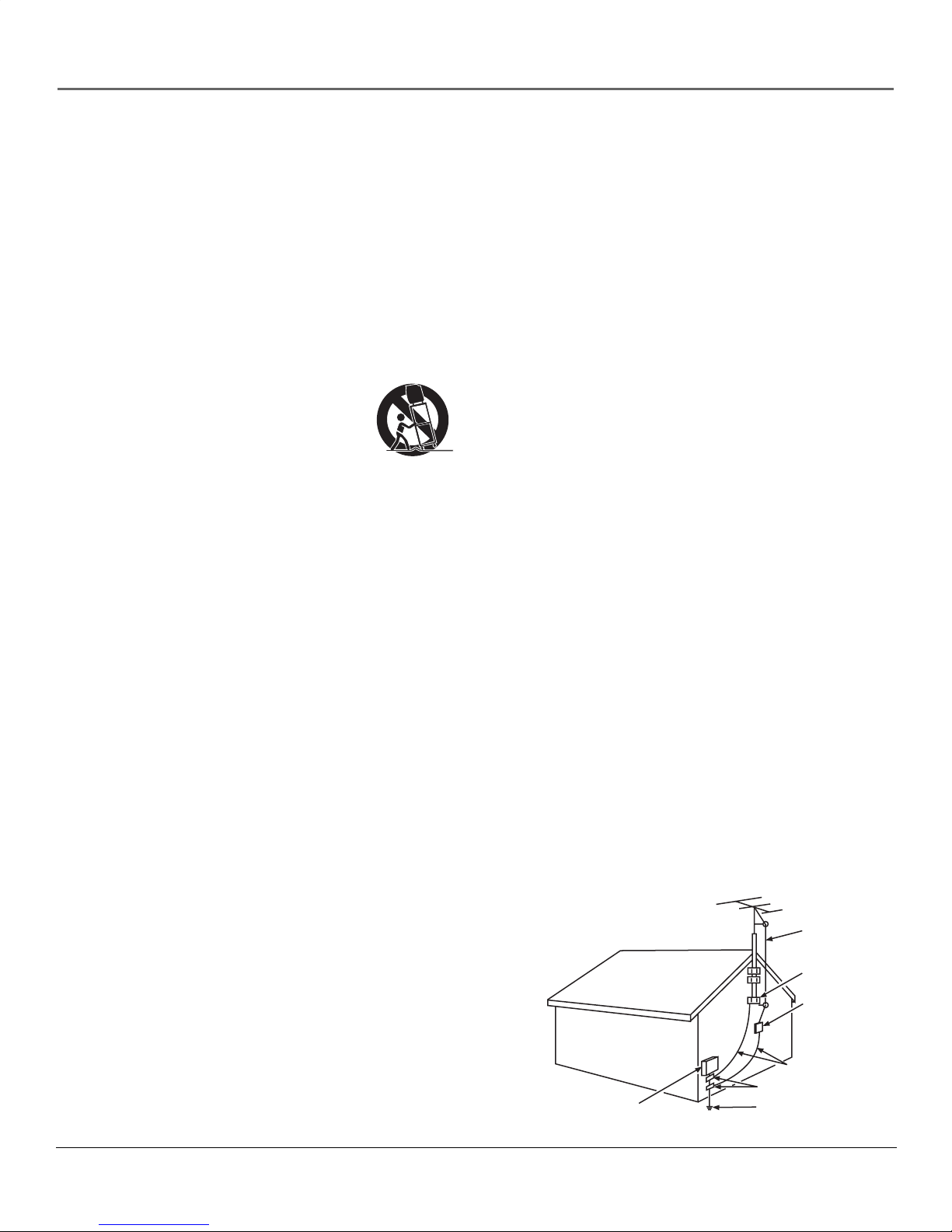
Example of Antenna Grounding as per
(NEC) National Electrical Code
ELECTRIC SERVICE
EQUIPMENT
ANTENNA
LEAD IN
WIRE
GROUND CLAMP
ANTENNA
DISCHARGE UNIT
(NEC SECTION 810-20)
GROUNDING CONDUCTORS
(NEC SECTION 810-21)
GROUND CLAMPS
POWER SERVICE GROUNDING
ELECTRODE SYSTEM
(NEC ART 250, PART H)
1
Page 4

Table of Contents
Important Safeguards.................................................................................................................. 1
Front of the TV............................................................................................................................. 3
Back and Side of the TV............................................................................................................... 3
Connections & Setup
Connecting to AC Power ............................................................................................................. 4
Basic Operation............................................................................................................................ 4
Antenna and Cable TV Connections........................................................................................... 4
Connecting Other Components .................................................................................................. 6
Using the Remote Control
Buttons on the Remote Control.................................................................................................. 6
Using the TV's Features
TV Operation................................................................................................................................ 8
Setting the Language .................................................................................................................. 8
Setting Channels.......................................................................................................................... 9
Sleep Function.............................................................................................................................. 9
Using the Menu System
Navigating the Menus............................................................................................................... 10
Using the PICTURE menu........................................................................................................... 11
Using the P.LOCK menu ............................................................................................................. 12
Using the TIMER menu .............................................................................................................. 14
Using the PRESET menu............................................................................................................. 15
Using the EXTRA menu.............................................................................................................. 16
Other Information
Troubleshooting......................................................................................................................... 17
Specifi cations ............................................................................................................................. 17
Additional Jacks ......................................................................................................................... 17
Limited Warranty....................................................................................................................... 18
2
Page 5
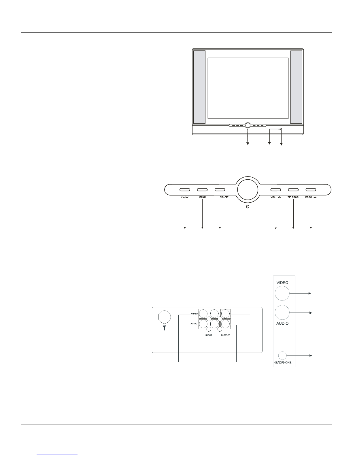
Front of the TV
1. Power button
2. Power indicator
3. Remote sensor
4. TV/AV button
5. MENU button
6. Volume down button
7. Volume up button
8. Program down button
Introduction
9. Program up button
Back and Side of the TV
10. Antenna jack
11. VIDEO INPUT jack
12. AUDIO INPUT jack (Mono)
13. AUDIO OUTPUT jack (Mono)
14. VIDEO OUTPUT jack
15. Side VIDEO INPUT jack (AV 2)
16. Side AUDIO INPUT jack (Mono) (AV 2)
1
4
5
6
32
79
8
15
16
17. Headphone
Notes:
The side AV jacks cannot be used with
the rear AV2 jacks (AV on the 14B042)
simultaneously.
Model 14B042 does not have AV OUT,
AV2, or headphone jacks.
3
10
11
12
13
17
14
Page 6

Connections & Setup
Wider Hole
and Blade
Polarized AC Cord Plug (One
blade is wider than the other)
AC Outlet
Connecting to AC Power
Use the AC polarized line cord provided for operation on AC. Insert the AC cord plug into a
polarized AC outlet.
NOTE:
If the polarized AC plug does not fi t into a nonpolarized AC outlet, do not attempt
to fi x or cut the blade of the plug. It is the user’s responsibility to have an electrician
replace the obsolete outlet.
Basic Operation
Plugging in the TV
Insert the power cord of the unit into a 90-140V AC outlet. Unplug the power when the unit will not be used for a long
period of time.
How to Power On/Off
You can turn on the power by using the POWER button on the front of the TV (or the POWER button on the remote
control).
Antenna and Cable TV Connections
Combination VHF/UHF Antenna (Single 75 ohm cable or 300 ohm twin-lead wire)
Connect the 75 ohm cable from a combination VHF/UHF antenna to the antenna jack. If your combination antenna has a
300 ohm twin-lead wire, use the 300-75 ohm matching transformer (not supplied).
Combination VHF/UHF Antenna (Separate VHF and UHF 300 ohm twin-lead)
Connect the UHF twin-lead wire to a combiner (not supplied). Connect the VHF twin-lead to the 300-75 ohm matching
transformer (not supplied). Attach the transformer to the combiner. Attach the combiner to the antenna jack.
Separate VHF/UHF Antenna
Connect the 75 ohm cable from the VHF antenna and the UHF antenna twin-lead to a combiner (not supplied). Attach the
combiner to the antenna jack.
Note: If your VHF antenna has a twin-lead wire, use the 300-75 ohm matching transformer (not supplied), then connect
the transformer to the combiner.
4
Page 7

Connections & Setup
For Subscribers to Basic Cable TV Service
For basic cable service not requiring a converter/descrambler box, connect the CATV 75 ohm coaxial cable directly to the
antenna jack on the back of the television.
For Subscribers to Scrambled Cable TV Service
If you subscribe to a cable service which requires the use of a converter/descrambler box, connect the incoming cable to the
converter/descrambler box and connect the output of the box to the antenna jack on the back of the television. Follow the
connections shown below. Set the television to the output of the converter/descrambler box (usually channel 3 or 4) and use
the converter/descrambler box to select channels.
For Subscribers to Unscrambled Basic Cable with Scrambled Premium Channels
If you subscribe to a cable service in which basic cable channels are unscrambled and premium channels require the use of a
converter/descrambler box, you may wish to use a two-set signal splitter (sometimes called a “two-set coupler”) and an A/B
switch box from the cable installer or an electronics supply store. Follow the connections shown below. With the switch in the
“B” position, you can directly tune any nonscrambled channels on your TV. With the switch in the “A” position, tune your TV
to the output of the converter/descrambler box (usually channel 3 or 4) and use the box to tune scrambled channels.
Combination VHF/UHF Antenna
Single 75 ohm cable
UHF Antenna
VHF Antenna
Incoming CATV
300 ohm twin-lead wire
Splitter
Take off the Splitter
300 ohm twin-lead wire
Single 75 ohm cable
300 ohm twin-lead wire
Converter/Descrambler
Converter/Descrambler
Splitter
A/B Switch
300-75 OHM MATCHING
TRANSFORMER
(not supplied)
300-75 OHM MATCHING
TRANSFORMER
(not supplied)
A
B
COMBINER
(not supplied)
ANT
Note:
This television has an extended tuning range
and can tune most cable channels without using
a cable company supplied converter box. Some
cable companies offer “premium pay channels” in
which the signal is scrambled. Descrambling these
signals for normal viewing requires the use of a
descrambler device which is generally provided by
the cable company.
5
Page 8
Connections & Setup
Connecting Other Components
The exact arrangement you use to interconnect various video and audio components to the TV is dependent on the model
and features of each component. Check the Owner’s Manual provided with each component for the location of video and
audio inputs and outputs.
The connection diagrams below are offered as suggestions. You may need to modify them to accommodate your particular
assortment of components. The diagrams are intended to show component video and audio interconnections only.
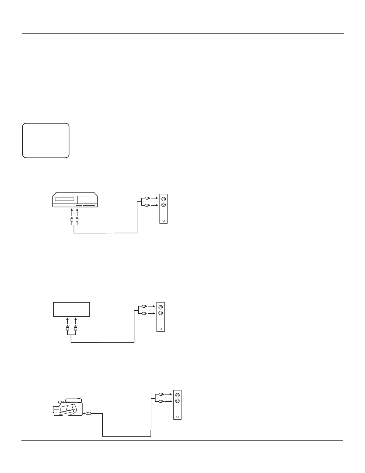
Press the TV/AV button to select the AV mode to use the TV as a monitor. Operate your VCR as usual.
AUX
TV/AV Selection
If you connect the TV to a VCR, camcorder or TV game, through the audio/video in jacks, use the
TV/AV button to make your selection. Press the TV/AV button repeatedly to select the desired mode.
“AUX” will display on the screen for 4 seconds.
To Connect the TV to a VCR
VCR
To Audio/Video OUT
(not supplied)
Side of the TV
VIDEO
AUDIO
To Connect the TV to a Video Game System
The TV can also be used as a display device for many video games. However, due to the wide variety of different types
of signal generated by these devices and subsequent hook-up variations required, they have not all been included in the
suggested connection diagrams. You’ll need to consult each component’s Owner’s Manual for additional information.
To Audio/Video OUT
TV GAME
Side of the TV
VIDEO
AUDIO
(not supplied)
To Connect the TV to a Camcorder
To playback from the camcorder, connect the camcorder to the TV as shown.
To AV OUT jack
(not supplied)
6
Side of the TV
VIDEO
AUDIO
Page 9

Using the Remote Control
Buttons on the Remote Control
(0-9) Number buttons Allows direct access to any channel. Two buttons must be
pressed to select a channel when you set ANTENNA to AIR. For channels 2 through 9,
press 0 fi rst, then the channel number (for example, 02, 12). Three buttons must be
pressed when you select a channel number under 20 if you set ANTENNA to CABLE,
and for channels above 19, you can enter the three digits directly. For example, 001,
019, 20, 100.
CODE Allows you to change your P.LOCK (Parental lock) password (see page 12).
DISPLAY Displays the current channel information (such as channel, time, etc.). Press
it again to exit.
FREE LISTEN This button has no function on this model.
MENU Displays the Main menu.
MUTE Reduces the TV’s volume to its minimum level. Press again to restore the
volume.
PICTURE Allows you to toggle the available picture settings: DYNAMIC, SOFT,
STANDARD, and PERSONAL.
POWER Turns the TV on and off.
PROG. (PROGRAM) buttons / Press the button to go to the next channel in
memory. Press the button to go to the previous channel in memory.
Q.VIEW (QUICK VIEW) Allows you to go back to the previous channel selected by
just pressing the Q.VIEW button. Press again to return to your last channel.
TIMER Sets the sleep timer.
TV/AV Toggles between regular TV programming and the Video Input Channels (TV1/
AV1/AV2).
VOL (VOLUME) buttons / Increases and decreases the volume.
Installing the Batteries
Before using the remote control for this fi rst time, you
need to install batteries.
1. Open the battery compartment cover.
2. Install two “AAA” batteries (not supplied).
3. Replace the battery compartment cover.
The batteries may last approximately one year
depending on how much the remote control is used.
For best performance, it is recommended that batteries
should be replaced on a yearly basis, or when the
remote operation becomes erratic. Do not mix old and
new batteries or different types.
Battery Precautions
These precautions should be followed when using batteries in
this device:
1. Use only the size and type of batteries specifi ed.
2. Be sure to follow the correct polarity when installing the
batteries as indicated in the battery compartment. Reversed
batteries may cause damage to the device.
3. Do not mix different types of batteries together (e.g.
Alkaline and Carbon-zinc) or old batteries with fresh ones.
4. If the device is not to be used for a long period of time,
remove the batteries to prevent damage or injury from
possible battery leakage.
5. Do not try to recharge batteries not intended to be
recharged; they can overheat and rupture. (Follow battery
manufacturer’s directions.)
7
Page 10

Using the TV’s Features
TV Operation
1. To turn on the TV, press the POWER button.
2. The VOLUME can be adjusted to a desired level by pressing the VOL (VOLUME) or button. The sound level will be
indicated on the TV screen.
3. Set the ANTENNA menu option to the appropriate setting. When shipped from the factory, this menu option is set to
CABLE. See “Setting Channels”.
TV - VHF/UHF channels
CABLE - CABLE TV channels
4. CH (CHANNEL) / buttons Press and release the CH (CHANNEL) or button. The channel automatically stops
at the next channel set into memory. Press and hold the button down to change channels more quickly.
For proper operation, before selecting channels, they should be set into the TV’s memory. See “Setting Channels”.
0-9 (Direct Channel Selection buttons) Press these buttons to select a channel. The channel number will appear on
the upper right corner of the TV screen. If an invalid channel number is selected, the display will revert to the previous
channel.
TV mode direct channel selection When the ANTENNA menu option is set to AIR, all channels can be instantly
selected by using two buttons (For example, to select channel 2, press “0”, then “2”. If you press only “2”, channel
selection will be delayed for a few seconds). For channels 10 and above, press the 2 digits in order.
CATV mode direct channel selection When the ANTENNA menu option is set to CABLE, channels can be selected as
follows:
1-9 Press “0” twice, then 1-9 as needed. For example, to select channel 2, press “002”.
10-12 Press “0”, then the remaining 2 digits. For example, to select channel 12, press “012”.
13-99 Press the 2 digits in order. For example, to select channel 36, press “36”.
100-125 Press the 3 digits in order. For example, to select channel 120, press “120”.
Note: If the station being viewed stops broadcasting, the TV will automatically shut off after 15 minutes.
Setting the Language
This TV can display the on screen displays and picture adjustments in English, Spanish or French.
1. Press the MENU button (the Main menu appears).
2. Press the PROG. or button to highlight EXTRA, then use the PROG. buttons again to highlight LANGUAGE.
3. Press the VOL or button to change the language to the desired setting: English (ENGLISH), Spanish (ESPAÑOL), or
French (FRANCAIS).
4. Press the MENU button to exit.
Note: If Spanish or French is chosen, the Closed Caption indicators will be in the selected language, but the Closed
Caption text will not be affected by the language selection.
8
Page 11

Using the TV’s Features
Setting Channels
This TV is equipped with a channel memory feature which allows channels to skip up or down to the next channel set into
memory, skipping over unwanted channels.
Before selecting channels, they must be programmed into the TV’s memory. In addition to normal VHF and UHF channels,
this TV can receive up to 113 Cable TV channels. If you have an off-air antenna, set the ANTENNA menu option to AIR.
When shipped from the factory, this menu option is set to CABLE.
1. Press the MENU button (the Main menu appears).
2. Press the PROG. or button to highlight PRESET, then use the PROG. buttons again to highlight ANTENNA.
3. Press the VOL or button to change the signal type to the desired setting: CABLE (cable TV) or AIR (off-air
antenna).
4. Press the PROG. or button to highlight AUTO PROGRAM, then press the VOL button to begin auto channel
search. This may take several seconds.
Adding / Deleting Channels
1. Press the MENU button (the Main menu appears).
2. Press the PROG. or button to highlight PRESET. CH NO. (Channel Number) is already highlighted.
3. Press the VOL or button or the number buttons to fi nd the channel you want to add or delete.
4. Press the PROG. or button to highlight CH (Channel), then press the VOL or button to select ADDED or
DELETED.
5. Repeat steps 2 - 4 for each channel to be added or deleted.
Sleep Function
1. Press the TIMER button on the remote control to display the set time 120, 90, 60, 30, 0 minutes for time-off. The unit
automatically turns off when the set time has elapsed.
2. To cancel the sleep timer, press the TIMER button repeatedly until 0 is displayed.
9
Page 12

Using the Menu System
Navigating the Menus
1. To enter a menu, press the MENU button, then use the PROG. / buttons to select the desired mode.
2. Press the VOL / buttons to select the mode you want to change.
3. Use the PROG. / buttons to select items within the submenu.
4. Use the VOL / buttons to change the settings.
5. Press MENU to return to the last menu.
PICTURE
P. LOCK
TIMER
PRESET
EXTRA
PICTURE
P. LOCK
TIMER
PRESET
EXTRA
PICTURE
P. LOCK
TIMER
PRESET
EXTRA
PICTURE
P. LOCK
TIMER
PRESET
EXTRA
CONTRAST
BRIGHT
COLOR
TINT
SHARPNESS
ENTER CODE
- - - -
CLOCK 11:30 AM
TIMER ON
ON TIME 11:45 AM
ON CH 05
OFF TIME 11:35 AM
CH NO. 10
CH ADDED
ANTENNA AIR
AUTO PROGRAM >
Picture
The PICTURE menu will allow you to make adjustments to your picture
settings.
P. Lock (Parental Lock)
You can set P.LOCK and V-CHIP in this menu.
Timer
The TIMER menu sets the clock on your TV and allows you to program
your TV for scheduled viewing by using the ON/OFF timer.
Preset
The PRESET menu provides several options for your channel settings,
including auto channel search and adding / deleting channels (see
"Setting Channels" on page 9).
PICTURE
P. LOCK
TIMER
PRESET
EXTRA
CC OFF
LANGUAGE ENGLISH
BACKGROUND ON
10
Extra
Set Closed Captioning, language, and background in this menu.
Page 13

Using the Menu System
To select the PICTURE menu
Display Highlight PICTURE Select
PICTURE
P. LOCK
TIMER
PRESET
EXTRA
CONTRAST
BRIGHT
COLOR
TINT
SHARPNESS
Using the PICTURE menu
CONTRAST
Adjust left to decrease picture contrast.
Adjust right to increase picture contrast.
Bright
Adjust left to darken the picture.
Adjust right to brighten the picture.
Color
Adjust left to decrease color intensity or saturation.
Adjust right to increase color intensity or saturation.
Tint
Adjust left to decrease the red tone.
Adjust right to increase the red tone.
Sharpness
Adjust left to soften the picture detail.
Adjust right to sharpen the picture detail.
11
Page 14

Using the Menu System
To select the P.LOCK menu
Display Highlight P.LOCK Select
PICTURE
P. LOCK
TIMER
PRESET
EXTRA
Figure 1
ENTER CODE
- - - -
Using the P.LOCK (Parental Lock)
menu
Note: When you enter the P.LOCK submenu for the fi rst time, NEW
CODE appears in red on the menu. Enter a four-digit number as
your password by pressing the 0-9 buttons. After you enter the
number, ENTER CODE appears in blue. Reconfi rm your password by
entering it again.
1. If you have already set your password and you want to enter the
P.LOCK menu, ENTER CODE appears in blue, as shown in Figure 1.
Enter your password.
Changing Your Password
1. If you need to change your password, press the CODE button
when ENTER CODE is displayed. OLD CODE appears. Enter your
old password, then NEW CODE appears in red. Enter a four-digit
number as your new password. After you enter the number, ENTER
CODE appears in blue. Reconfi rm your password by entering it
again.
If you forget your password, enter 4769 as your password and change it
to a new one.
PICTURE
P. LOCK
TIMER
PRESET
EXTRA
Figure 2
PICTURE
P. LOCK
TIMER
PRESET
EXTRA
CH LOCK
V- CHIP
LOCK ON
CH AIR 69
CH LOCK ON
CH Lock (Channel Lock)
You can lock individual channels with this feature.
LOCK
ON: Turns on CH LOCK.
OFF: Turns off CH LOCK.
CH AIR: Select the channel you want to lock. You can use VOL /
buttons or number buttons to input channel number.
Note: “CH CABLE ***” is displayed under CABLE mode.
CH LOCK
ON: If this is set to ON, the selected channel in the CH LOCK menu
cannot be viewed.
OFF: LOCK is deactivated and any selected channel for CH LOCK can
be viewed.
12
Page 15

Using the Menu System
Using the P.LOCK menu (continued)
PICTURE
P. LOCK
TIMER
PRESET
EXTRA
V- CHIP ON
MPAA RATING
TV RATING
Setting V-Chip
If you have already set your password and you want to enter the P.LOCK
menu, ENTER CODE appears in blue, as shown in Figure 1. Enter your
password.
V-CHIP
ON: Turns on V-CHIP.
OFF: Turns off V-CHIP.
MPAA Rating
BLOCK prohibits the blocked channel. VIEW permits you to watch channels. If a high rating is set
to VIEW, all the ratings below it will also be set to VIEW; if a low rating is set to BLOCK, all the
ratings above it will also be set to BLOCK.
G: General Audiences
PG: Parental Guidance Suggested.
PG-13: Parents Strongly Cautioned.
R: Restricted.
NC-17: No one under 17 admitted.
X: For Adults.
TV Rating
Just as with the movie ratings, BLOCK prohibits the blocked channel. VIEW permits you to watch
channels. If a high rating is set to VIEW, all the ratings below it will also be set to VIEW; if a low
rating is set to BLOCK, all the ratings above it will also be set to BLOCK.
Y: All children.
Y7: Directed to older children.
The following item can be set for this rating:
FV: Fantasy violence.
G: General Audience.
PG: Parental Guidance suggested.
The following items can be set for this rating:
D: Suggestive Dialogue.
L: Strong language.
S: Sexual situation.
V: Violence.
14: Parents strongly cautioned.
The following items can be set for this rating:
D: Suggestive Dialogue.
L: Strong language.
S: Sexual situation.
V: Violence.
MA: Mature Audience only.
The following items can be set for this rating:
L: Strong language.
S: Sexual situation.
V: Violence.
13
Page 16

Using the Menu System
To select the TIMER menu
Display Highlight TIMER Select
PICTURE
P. LOCK
TIMER
PRESET
EXTRA
CLOCK 11:30 AM
TIMER ON
ON TIME 11:45 AM
ON CH 05
OFF TIME 11:35 AM
Using the TIMER menu
Clock
Press the number buttons to set the hour and minute.
Press the VOL / buttons to switch between AM and PM.
Timer
ON: Set the timer to be active.
OFF: Turn off the timer.
Note: The clock must be programmed before you can use the timer.
On Time
Press the number buttons to set the hour and minute.
Press the VOL / buttons to set AM or PM.
Note: ON-TIME will turn on the TV automatically at the preset time.
TIMER must be set to ON for this feature to work.
On CH (Channel)
You can press the 0-9 number buttons or PROG. / buttons to select
your desired channel.
Off Time
Press the number buttons to set the hour and minute.
Press the VOL / buttons to set AM or PM.
Note: OFF-TIME will turn off the TV automatically at preset time,
TIMER must be set to ON for this feature to work.
Note: When you unplug the power cord, the time will be reset.
You'll need to set the clock again.
14
Page 17

Using the Menu System
To select the PRESET menu
Display Highlight PRESET Select
PICTURE
P. LOCK
TIMER
PRESET
EXTRA
CH NO. 10
CH ADDED
ANTENNA AIR
AUTO PROGRAM >
Using the PRESET menu
CH NO. (Channel Number)
Press the number buttons or VOL / buttons to select your desired
channel.
CH (Channel)
ADDED: Adds the channel that you selected in CH NO.
DELETED: Deletes the channel that you selected in CH NO.
Antenna
AIR: Select to receive off-air antenna signals.
CABLE: Select to receive cable signals.
Auto Program
Searches for all available channels.
Note: TIMER, ON TIME, ON CH, and OFF TIME items in the TIMER
submenu will be reset when AIR/CABLE modes are switched.
15
Page 18

Using the Menu System
To select the EXTRA menu
Display Highlight EXTRA Select
PICTURE
P. LOCK
TIMER
PRESET
EXTRA
CC OFF
LANGUAGE ENGLISH
BACKGROUND ON
Using the EXTRA menu
Closed Captioning
C1: Displays Caption 1.
C2: Displays Caption 2.
C MUTE: Caption is displayed when the volume is muted.
TEXT1: Displays TEXT 1.
TEXT2: Displays TEXT 2.
OFF: Turns off Closed Captioning.
Tips:
Captions prepared for TV programs can be pre-recorded (movie,
daytime dramas etc.). This type of caption is normally 1 or 2 lines of
text.
Text can include: captioned program listings, farm news, sports
reports and news reports for hearing impaired persons or general
wire-service news. This type of caption does not generally relate to
the program. The displays may be several lines of text information
at a time.
Language
Allows you to display the menu languages in English, Spanish, or French.
Background
With this option, you can choose to display a blue background when no
signal is present.
16
Page 19

Other Information
Troubleshooting
You can correct most problems you have with your product
by consulting the following troubleshooting list. If you need
service, please refer to the service centers in this user's guide
or contact the store where you purchased this product.
TV Problems
TV does not operate.
• Make sure the power cord is plugged in.
• Try another AC outlet.
• Power is off ; check fuse or circuit breaker.
Poor sound or no sound.
• Station or CATV experiencing problems; tune to another
station.
• Check sound adjustments (Volume and Mute).
• Check for source of possible interference.
Poor picture or no picture.
• Station or CATV experiencing problems; tune to another
station.
• Check antenna or CATV connections; reorient antenna.
• Check for source of possible interference.
• Check picture adjustments.
Poor reception on some channels.
• Station or CATV experiencing problems; tune to another
station.
• Station signal is weak; reorient antenna to receive weaker
station.
• Check for sources of possible interference.
Poor color or no color.
• Station or CATV experiencing problems; tune to another
station.
• Check picture adjustments.
• Make sure Antenna Mode is correct.
• Check antenna or CATV connections; reorient antenna.
• Check for sources of possible interference.
Picture wobbles or drifts.
• Station or CATV experiencing problems; tune to another
station.
• CATV company is scrambling signal.
• Check antenna orientation.
No CATV reception.
• Check CATV connections.
• Make sure Antenna Mode is correct.
• Station or CATV system problems; try another station.
Horizontal or diagonal bars on screen.
• Check antenna connections and reorient antenna.
• Make sure Antenna Mode is correct.
• Check for source of possible interference.
No remote operation.
• Batteries are weak, dead or inserted improperly.
• Remote is out of range; move closer to TV.
• Make sure remote is aimed at sensor.
• Confi rm no obstructions between remote and TV.
• Make sure power cord is plugged in.
TV shuts off.
• Sleep Timer is set.
• Power interrupted.
No reception above channel 13.
• Make sure Antenna Mode is correct.
• If using UHF antenna, check connections.
Specifi cations
Model: 21B042 14B042
Color System: NTSC NTSC
AC Power Input: 90-140V, 60Hz 90-140V, 60Hz
Power Consumption: 80 Watts 70 Watts
Audio Output: 2x2 Watts 2x1 Watts
Picture Tube: 21" 14"
(measured diagonally)
Dimensions: 23.2" (W) x 16.2" (W) x
17.9" (D) x 14.6" (D) x
18.5" (H) 13.0" (H)
Weight: 48.7 lbs 40.1 lbs
Speaker: 18 ohm/7W 16 ohm/3W
Models:
Tuner Type: 181 Channel,
Quartz PLL Frequency Synthesized
Remote Control: 24 Buttons, 2 x AAA Batteries
Receiving Channels: VHF 2-13
UHF 14-89
CATV 01-125
Antenna Input Impedance: 75 ohm (VHF/UHF/CATV)
Coaxial Input
21B042 & 14B042
Additional Jacks
Model: 21B042 14B042
Rear Video Output: Yes No
Rear Audio Output: Yes No
Headphone Output: Yes No
17
Page 20

Other Information
Limited Warranty - United States
What your warranty covers:
• Any defect in materials or workmanship.
For how long after your purchase:
• One year for labor and parts.
• The warranty for rental units begins with the fi rst rental or 45 days from date of shipment to the rental fi rm, whichever comes fi rst.
What we will do:
• Pay any Authorized RCA Service Center the labor charges to repair your unit.
• Pay any Authorized RCA Service Center for the new or, at our option, refurbished replacement parts required to repair your unit.
How you get service:
• Take your unit to any Authorized RCA Service Center. To identify your nearest Authorized RCA Service Center, consult your dealer.
• Show the Authorized Service Center Representative your evidence of purchase date or fi rst rental.
• Pick up your unit when repairs are completed.
What your warranty does not cover:
• Customer instruction. (Your Owner’s Manual provides information regarding operating instructions and user controls. For additional
information, ask your dealer.)
• Installation and set-up service adjustments.
• Batteries.
• Damage from misuse or neglect.
• Products which have been modifi ed or incorporated into other products.
• Products purchased or serviced outside the USA.
• Acts of nature, such as but not limited to lightning damage.
Product Registration:
• Please complete and mail the Product Registration Card packed with your unit. It will make it easier to contact you should it ever be
necessary. The return of the card is not required for warranty coverage.
Limitation of Warranty:
• THE WARRANTY STATED ABOVE IS THE ONLY WARRANTY APPLICABLE TO THIS PRODUCT. ALL OTHER WARRANTIES,
EXPRESS OR IMPLIED (INCLUDING ALL IMPLIED WARRANTIES OF MERCHANTABILITY OR FITNESS FOR A PARTICULAR
PURPOSE) ARE HEREBY DISCLAIMED. NO VERBAL OR WRITTEN INFORMATION GIVEN BY TTE TECHNOLOGY, INC., ITS
AGENTS OR EMPLOYEES SHALL CREATE A GUARANTY OR IN ANY WAY INCREASE THE SCOPE OF THIS WARRANTY.
• REPAIR OR REPLACEMENT AS PROVIDED UNDER THIS WARRANTY IS THE EXCLUSIVE REMEDY OF THE CONSUMER. TTE
TECHNOLOGY, INC. SHALL NOT BE LIABLE FOR INCIDENTAL OR CONSEQUENTIAL DAMAGES RESULTING FROM THE USE
OF THIS PRODUCT OR ARISING OUT OF ANY BREACH OF ANY EXPRESS OR IMPLIED WARRANTY ON THIS PRODUCT.
THIS DISCLAIMER OF WARRANTIES AND LIMITED WARRANTY ARE GOVERNED BY THE LAWS OF THE STATE OF INDIANA.
EXCEPT TO THE EXTENT PROHIBITED BY APPLICABLE LAW, ANY IMPLIED WARRANTY OF MERCHANTABILITY OR FITNESS
FOR A PARTICULAR PURPOSE ON THIS PRODUCT IS LIMITED TO THE APPLICABLE WARRANTY PERIOD SET FORTH
ABOVE.
How state law relates to warranty:
• This warranty gives you specifi c legal rights and you may have other rights that vary from state to state.
If you purchased your product outside the United States:
• This warranty does not apply. See your dealer for warranty information.
Service calls, which do not involve defective materials or workmanship, are not covered by this warranty.
Costs of such service calls are the sole responsibility of the purchaser.
Limited Warranty - Other Countries
Outside of Mexico, Chile and the United States please contact your selling dealer for any warranty.
18
Page 21

Other Information
_
_
POLIZA DE GARANTIA
TTE México S.A. de C.V. garantiza este producto en todas sus partes y
mano de obra, contra cualquier defecto de fabricación y funcionamiento,
a partir de la fecha de entrega al cliente final. Bajo el siguiente término:
Televisores c/cinescopio de 36,6
cm. (14 pulgadas) y menores
Televisores c/cinescopio de 48,3
cm. (19 pulgadas) y mayores.
Televisión de Proyección 1 año 1 año
Videocaseteras 1 año 1 año
Videocámaras 1 año 1 año
Equipos de Audio 1 año 1 año
Reproductor de DVD 1 año 1 año
Accesorios 1 año 1 año
1. Para ser efectiva esta garantía se requiere presentar esta póliza o factura de
2. TTE México se compromete a reparar y/o reponer las piezas y componentes
3. Todos los productos deberán ser llevados a cualquier Centro de Servicio
4. El tiempo de reparación en ningún caso será mayor a 30 días, contados a partir de
5. Para la adquisición de partes y accesorios, contactar al 01-800-1117221 o acudir a
TTE México.
NOTAS:
En caso de extravío de la póliza, el consumidor podrá recurrir a su distribuidor para
Para su comodidad, solicite informes sobre la localización del Centro de Servicio
TTE México S.A. de C.V.
Álvaro Obregón No. 151. Piso 13, Col. Roma.
México, D.F. C.P. 06700; Apartado Postal 41-540
Producto Partes Mano de Obra
2 años cinescopio.
1 año otras partes.
2 años cinescopio.
1 año otras partes.
1 año
1 año
CONDICIONES
compra debidamente sellada y requisitada, junto con el producto en cualquiera de
nuestros Centros de Servicios Autorizados, (que se indican en la hoja anexa), o en
el lugar donde fué adquirido.
defectuosos sin cargo al consumidor, o en case de que a criterio de dicha
empresa no sea posible la reparación, cambiar por un nuevo, exactamente
del mismo modelo o su similar. Los gastos de transportación dentro de la red
de servicios, que se deriven del cumplimiento de esta póliza de garantía, serán
cubiertos por TTE México.
Autorizado, excepto los televisores con pantalla de 63,5 cm (25 pulgadas) o más,
los cuales serán reparados en el domicilio del cliente.
la recepción del producto en el Centro de Servicio Autorizado.
su reposición, previa presentación de la factura o nota de compra.
Autorizado más cercano a su domicilio, llamando al:
01-800-1117221
No. de Póliza:
___________
PRODUCTO: ____________________________________________________
MODELO: ___________________ NO. DE SERIE ______________________
EXPEDIDA A: __________________________________________________
DIRECCION: ___________________________________________________
_______________________________________________________________
NOMBRE:
_______________________________________________________
DIRECCION:
_______________________________________________________________
FECHA DE COMPRA:
SELLO Y FIRMA DEL VENDEDOR
•
•
•
_____________________________________________________
______________________________________________
ESTA GARANTIA NO TIENE VALIDEZ EN LOS SIGUIENTES CASOS
Cuando el producto se hubiese utilizado en condiciones distintas a las normales.
Cuando el producto no hubiese sido operado de acuerdo al instructivo de uso
que se le acompaña.
Cuando el producto hubiese sido alterado o reparado por personas no
autorizadas por TTE México S.A de C.V.
DATOS DEL PRODUCTO
DATOS DEL CLIENTE
19
Page 22

Other Information
RED NACIONAL DE SERVICIO
Centro de Servicios Autorizados Express
(servicio en 24 horas)
AGUASCALIENTES
Electrónica JIMSA
Av. Adolfo López Mateos No. 230 Ote.
Col. Centro
Aguascalientes, Ags. C.P.2000
Tel (449) 915 5181; 978 0757
Fax (449) 915 8100
BAJA CALIFORNIA NORTE
Electrónica General Internac
Blvd. Insurgentes No. 16174, Loc. 2AC.
Plaza de Abastos Los Almos
Tijuana, BCN C.P. 22440
Tel/Fax (664) 6212215
Baja Electronics
Hacienda de Corralejo No. 2099
Col. Hidalgo
Mexicali, B.C.N. C.P. 21389
Tel/Fax (686) 5619818, 5619808
BAJA CALIFORNIA SUR
Digital Sound
16 de Septiembre No. 390
Col. Centro
La Paz, Baja California Sur
Tel/Fax (612) 1232017
Video Servicio Beluz
Carretera a todos Santos No. 32
Col. Infonavit Las Brisas.
Los Cabos San Lucas, BCS C.P. 23410
Tel/Fax (624) 14313 65
CAMPECHE
Videoservicio
Av. López Mateos No. 24
Col. Barrio Sn. Román.
Campeche, Camp. C.P.24040
Tel (981) 816 3333
Fax (981) 811 0669
CHIAPAS
KC Video
10a. Norte Oriente No. 153A
Col. Centro
Tuxtla Gutiérrez, Chis. C.P. 29000
Tel/Fax (961) 618 1908;
Tel (961) 618 3643
Serv. Elec. Especializado
Cuahutémoc No. 2A
Col. Centro, C.P. 29200
San. Cristóbal de las Casas, Chis.
Tel/Fax (967) 6781355
Ele Aplicada Serv Digitales
4a. Av., Sur No. 51
Col. Centro, C.P. 30700
Tapachula, Chis.
Tel (962) 6269998
Fax (962) 6256953
CHIHUAHUA
Zener Electrónica
Av.Teófilo Borunda Sur # 300
Col. Centro
Chihuahua, Chih. C.P. 31000
Tel/Fax (614) 4371901
Tel (614) 4371902
Eletrónica Union
Laguna de Tamiahua 7255 local 13
Col.Infonavit San Lorenzo. C.C.Calesa
Cd.Juárez, Chihuahua C.P.32420
Tel/Fax (656) 6177890
Electrónica Tony
Av. Tercera Pte. No. 213
Col. Centro
Cd. Delicias, Chihuahua
Tel/Fax (639) 4743026
México, D.F.
Digital Service Vallejo
Av. 3 A No. 12, Local 2
Col. Santa Rosa
Tels (55) 53677347 y 53677349
Tel/Fax (55) 53889621
Taller Electrónico Tony
20 de Noviembre No. 1521
Col. Centro.
Cd. Camargo, Chihuahua. C.P.
Tel/Fax (639) 4743026
COAHUILA
Electrónica Profesional
Blvrd. Francisco Coss No. 450-1
Col. Centro
Saltillo, Coah C.P. 25000
Tel/Fax (844) 4123044
Audio y Video Electrónica
Miguel Blanco 307-A
Col Zona Centro.
Monclova, Coahuila. C.P. 25700
Tel/Fax (866) 6339406
Vacom
Av. Morelos 1016 ote.
Col. Centro
Torreón, Coah. C.P. 27000
Tel 01 871 718 39 05, 7 22 15 51
Fax 01 871 718 11 98
Serel. S.A.
Calle Nueva No.307
Col. González
Piedras Negras,
Coahuila. C.P.26000
Tel/Fax (878) 7827104
Multiservicios del Norte
5 de Mayo 295 Sur.
Col. Centro
Sabinas, Coahuila. C.P. 26700
Tel/Fax (861) 6126431
México, D.F.
COLIMA
TV. Servicio Saturno
Nigromante No. 136 Altos
Col. Centro
Colima, Col. C.P. 28000
Tel/Fax (312) 3145554, Tel (312) 3145000
Centro De Rep. Electrónicas
Tucanes # 66 Barrio 5
Col. Valle de las Garzas.
Manzanillo, Col. C.P.
Tel (314) 3323004
Tel/Fax (314) 3354667
DISTRITO FEDERAL
Laboratorio Electrónico.
Retorno 52 Cecilio Róbelo, Edif 1, Loc16-02
Col. Jardín Balbuena
México, D.F.
Tel/Fax (55) 57620264, 57626494
ADE Electrónica
Corea No. 79
Col. Romero Rubio
México D.F. C.P. 15400
Tel/Fax (55) 57027223
Electro Digital.
Av. Tl·huac No. 4798
Barrio de S. Sebastián Tulyehualco Xoch.
México D.F.
Tel/Fax (55) 21614639
SIMEL
Rio Churubusco No. 2215
Col. Agrícola Oriental
México, D.F. C.P. 08500
Tel (55) 57563785, Fax (55) 57560883
CICOSA
Ahuizotl # 94
Col. La Preciosa
México, D.F. C.P.02460
Tel 5347 0302, 5561 6943
Fax 5532 0663
Guadalajara, Jal.
Servicio Especializado de Jalisco
Enrique Díaz de León No. 821
Col. Sagrada Familia
Guadalajara, Jal.
Tel (33) 31267431, 31267430
38253229, 38258262
Novatron.
Diag. San Antonio No. 1213
Col. Narvarte
México, D.F. C.P. 03020
Tel (55) 56390812
Fax (55)56391184
Premium Technical Support
Calzada Taxqueña # 1423
Col. Campestre Churubusco
México, D.F.
Tel 53362467
Centro de Servicio Electrónico
Nicolás San Juan 806 P.B.
Col. Del Valle
México, D.F. C.P.03100
Tel 5536-2575, 55367103
Fax 5687-1305
DURANGO
Macroservicios.
Calle Patoni No. 105 sur.
Col. Centro
Durango, Dgo.
Tel/Fax (618) 812 26 86
ESTADO DE MEXICO
Digital Service Prensa
Prensa No. 1253
Col. Prensa Nal. Ind. Vallejo.
Tlanepantla, E.D.M. C.P. 54170
Tel (55) 55877599 y 55673972
Fax (55) 55878971
SHUREE Electrónica
Av. De los Maestros No. 113A
Col. Pensiones, C.P. 50060
Toluca, EDM.
Tel (722) 2149330, 2133424
Monterrey. N.L.
Audio Estéreo Aguilar
Gral. Zuazua 738 Nte.
Col. Centro
Monterrey. N.L.
Tel (81) 83724989
83755884
TV Servideo
Oriente 9 No. 182
Col. Reforma
Cd. Neza, Edo. De Méx. C.P. 57840
Tel (55) 58572547
Fax (55) 58576399
Electrónica CIS
Reforma No. 36
Col. Centro
Chalco, Edo. de Méx. C.P. 56600
Tel/Fax (55) 3092 3060
GUANAJUATO
Tecnología Electrónica
Blvd. Adolfo López Mateos No. 2820B
Col. Haciendas El Rosario
León, Gto. C.P. 37130
Tel/Fax (477) 4702701
Electrónica Siglo XXI
Naranjo No. 950
Col. Flores Magón.
Irapuato, Guanajuato. C.P. 36180
Tel/Fax (462) 626 9823, 660 1238
Tele Servicio Chucho.
Blv Adolfo López Mateos No 510 Pte
Col. Centro, C.P. 38000
Celaya, Gto.
Tel/Fax (461) 6130591
Tele Radio Ortega.
Av. 16 de Septiembre No. 1076
Col. Centro, C.P. 38600
Acambaro, Gto.
Tel/Fax (417) 1720780
GUERRERO
Nueva Elec. Auditron
Aquiles Serdán No. 14B
Col. Centro
Acapulco, Gro. C.P. 039300
Tel (744) 4826242
Tel/Fax (744) 4832062
Ingeniería Electrónica
Antonia Nava de Catalán No.17
Col. Centro
Chilpancingo, Gro. C.P.39000
Tel (747) 4717273
Tel/Fax (747) 4948365
HIDALGO
Servicio Electrónica Avanzada
Plaza Comercial Quinta Bonita Loc.11
Fraccionamiento Quinta Bonita
Pachuca, Hgo. C.P. 42083
Tel/Fax (771) 7132436
Electrónica Especializada
Independencia No. 102 Loc. C
Col. Centro, C.P. 43600
Tulancingo, Hgo,
Tel/Fax (775) 7552654 Tel (775) 7539120
JALISCO
Serv. Esp. De Jalisco
Ignacio Ramírez No. 567
S.H. Sta. Teresita
Guadalajara, Jal. C.P. 44200
Tel/Fax (33) 38253229 Tel (33) 38270721
Electrónica Integral
Candelaria No. 202, Esq. Analco
Col. Sta. María
Puerto Vallarta, Jal. C.P. 48348
Tel (322) 2243736
Tel/Fax (322) 2248590
Setesa
5 de Febrero No. 2786
Col. Rancho Blanco
Tlaquepaque, Jalisco. C.P. 44890
Tel (33) 36354404
Tel/Fax (33) 36351875
MICHOACAN
Alka Electrónica
García de León No. 271
Col. Chapultepec Sur.
Morelia, Mich. C.P. 58260
Tel (443) 3145521, 3159036
Tel/Fax (443) 3159425
Centro Electrónico
Justo Mendoza No. 12
Col. Centro
Uruapán, Mich. C.P. 60000
Tel (452) 5243778, 5240838
Tel/Fax (452) 5245909
Multiserv Prof. Zamora
Colón No. 181-1 Ote.
Col. Centro
Zamora, Mich. C.P. 59600
Tel/Fax (351) 5155416
MORELOS
Electrónica Hertz
Insurgentes No. 190
Col. Emiliano Zapata
Cuautla, Mor. C.P. 62744
Tel/Fax (735) 3538410
Electrónica Hertz
Libertad No. 130.
Col. Carolina
Cuernavaca, Mor. C.P. 62190
Tels (777) 3139092, 3119127
NUEVO LEON
Audio Estéreo Aguilar
Gral. Zuazua 738 Nte.
Col. Centro
Monterrey, Nvo. León. CP. 64000
Tels (81) 83724989, 83755440
Tel/Fax (81) 83755884
Técnica Especializada
Diego Díaz de Berlanga # 206
Col. Residencial Nogalar C.P.66480
San Nicolás de los Garza, Nvo.León.
Tel (81) 86762799 y 80402747
Fax (81) 80402747
Teleservicio Murillo
Pino Suarez # 501 Sur.
Col. Centro
Cd. Linares, Nvo León. C.P. 67700
Tel/Fax (821) 2126650
NAYARIT
Electrónica Show
San Luis No. 118 sur
Col. Centro
Tepic, Nay. C.P. 63000
Tel/Fax (311) 2145800
OAXACA
E-Prom Lab.Electrónico
Modesto Díaz No.403
Col.Ricardo Flores Magón,
por volcanes
Oaxaca, Oax. C.P.68020
Tel/Fax (951) 5201189
RED NACIONAL DE SERVICIO
Telestar
Av.Libertad No. 1557
Col. La Piragüa
Tuxtepec, Oaxaca
Tel/Fax (287) 8752544
PUEBLA
Serv. Express Electrónico
Prol. Reforma No. 6908A
Col. La Libertad
Puebla, Pue. C.P. 72130
Tel (222) 2497819
Tel/Fax (222) 2313293
Centro de Servicio P.C.
Av. Independencia Pte. No. 407
Col. Centro
Tehuacán, Puebla C.P. 75700
Tel/Fax (238) 3823835
QUERETARO
Blauton Industrial
Av. Universidad No. 44B
Col. Pathe
Querétaro, Qro. C.P. 76020
Tels (442) 2232266, 2234934
Tel/Fax (442) 2232267
QUINTANA ROO
Electrónica Beta
Av. Sun Yax Chen No. 43 Loc. 4
Col. Centro
Cancún, Q. Roo. C.P. 77508
Tel (998) 8845412
Tel/Fax (998) 8873813
Electrónicos y Mas
Ignacio Zaragoza No. 204-A
Col. Centro. C.P. 77000
Chetumal, Q. Roo
Tels (983) 8326663, 8324622
Fax (983) 8326014
SAN LUIS POTOSI
Electrónica Especializada
Nicolás Zapata # 1015-A
Col. Tequisquiapán
San Luis Potosí, SLP. C.P. 78250
Tel (444) 8176279
Tel/Fax (444) 8176279
Estéreo Car
Negrete No. 612
Col. Centro
Cd. Valles, SLP. C.P. 79000
Tel/Fax (481) 3820651
SINALOA
Serv. Electrónico del Pacífico
Mariano Escobedo No. 1022
Col. Centro
Mazatlán, Sin. C.P. 82000
Tel/Fax (669) 9820155
Reparaciones Electrónicas
J.Jose Ríos No. 178 ote.
Col. Miguel Alemán.
Culiacán Sinaloa. C.P. 80200
Tel/Fax (667) 7168132,
(667) 7165145
Electrónica Morelos.
Morelos No. 201 ote
Col. Centro.
Los Mochis, Sinaloa. C.P. 81200
Tel/Fax (668) 8120588
SONORA
Wong's Electrónicos
12 de Octubre No.116 Esq.Q.Roo.
Col. San Benito
Hermosillo, Son. C.P. 83180
Tel (662) 2105495
Tel/Fax (662) 2100586
Dasetronik.
Guerrero No. 308-A este.
Col. Centro.
Navojoa, Sonora. C.P. 85800
Tel (642) 4224064
Fax (642) 4213664
Audio Video Electrónica
Av. Zaragoza No. 516 pte.
Col. Centro.
Cd. Obregón, Sonora. C.P. 85000
Tel (644) 4143828
Fax (644) 4147575
Electrónica Universal.
Calle 29 Av. Alfonso Idberry No. 401
Col. Centro
Cd. Guaymas, Sonora. C.P. 85400
Tel/Fax (622) 2229411
TABASCO
Elec. Sigma de Tabasco
Av. Gregorio Méndez No. 2819
Col. Atasta
Villahermosa, Tab. C.P. 86100
Tel (993) 3545410
Tel/Fax (993) 3540033
TAMAULIPAS
Electrónica Digital
Independencia No. 112 esq. 11
Col. Centro
Matamoros, Tamps. C.P. 88000
Tel/Fax (868) 8135013
Centro de Servicio Lugo
Rosalinda Guerrero No. 285
Col. Prol. Longoria
Reynosa, Tamps. C.P. 88699
Tel/Fax (899) 9249243
Esp. Electrónicas
Matamoros Poniente 225
Col. Centro
Cd. Victoria, Tamps. C.P. 87000
Tel (834) 3125193
Fax (834) 3125193
Micronics
Calle 10 No. 607.
Col. Jardín 20 de Noviembre
Madero, Tamps. C.P. 89440
Tel (833) 2159689
Fax (833) 2103882
Laboratorio Electrónico
Washington 3142
Col. Juárez (Centro)
Nuevo Laredo, Tamps. C.P. 88000
Tel (867) 7149592
Tel/Fax (867) 7149852
Electrónica Emmanuel
Obregón No. 206 Pte.
Zona Centro
Cd. Mante, Tamaulipas. C.P. 89800
Tel/Fax (831) 2329081
TLAXCALA
Sexel. De Tlaxcala
Av. Revolución No. 33 Local A.
Col. Atenpán
Tlaxcala, Tlax.
Tel/Fax (246) 462 9660
VERACRUZ
Serv Técnicos Prof.
Av. 13 No. 400 Esq.
Calle 4
Col. Bella Vista
Córdoba, Ver. C.P. 94500
Tel (271) 7127322
Fax (271) 7122539
Electrónica Arizona
Acosta No. 9
Zona Centro
Jalapa, Ver. C.P. 91000
Tel (228) 8903561 y 62
Electrónica Digital
Av. Juárez No. 516
Col. 27 de Septiembre
Poza Rica, Ver. C.P. 93320
Tel (782) 8229899
Tel/Fax (782) 8236949
Electrónica DICA
F. del Paso y Troncoso No. 908
Col. Centro
Veracruz, Ver. C.P. 91700
Tel (229) 9312296
Tel/Fax (229) 9312033
Seguridad Plus.
SUR 15 # 210 ENTRE ORIENTE 4 Y 6
Col. Centro
Orizaba, Ver. C.P.94300
Tel/Fax (272) 7247676
YUCATAN
Servicentro
Calle 70 No. 443 x calle 49 dept.5
Col. Centro
Mérida, Yuc. C.P. 97000
Tel (999) 9285428 y 9233997
Tel/Fax (999) 9285905
ZACATECAS
Electrónica Mario.
Morelos
Poniente No. 1214
Col. Centro
Zacatecas, Zac.
C.P. 98000
Tel/Fax (492) 9227561
20
Page 23

Page 24

Visit the RCA website at www.rca.com
Please do not send any products to the Indianapolis address listed in this manual or on the carton. This will only add delays in
service for your product.
IMPORTER (for Mexico only):
TTE México, S.A. de C.V.
Álvaro Obregón No. 151. Piso 13
Col. Roma. Delegación Cuauhtémoc
C.P. 06700 México D.F.
Teléfono: 52-55-11-020360
RFC: TME-040528-7S2
EXPORTER:
TTE Technology, Inc.
10330 North Meridian Street
Indianapolis, IN 46290
©2004 TTE Technology, Inc.
Trademark(s)® Registered
Marca(s) Registrada(s)
Printed in Mexico
TOCOM 1640641B
 Loading...