

Page 1
Webringgood things to life.
Page 2
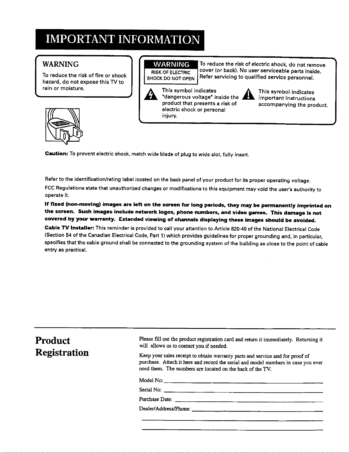
WARNING
To reduce the risk of fire or shock
hazard, do not expose this "IV to
rain or moisture.
A
Caution: To prevent electdc shock, match wide blade of plug to wide slot, fully insert.
Refer to the identification/rating label located on the back panel of your product for its proper operating voltage.
FCC Regulations state that unauthorized changes or modifications to this equipment may void the user's authority to
operate it.
If fixed (non-moving) images are left on the screen for long periods, they may be permanently imprinted on
the screen. Such images include network loges, phone numbers, and video games. This damage is not
covered by your warranty. Extended viewing of channels displaying these images should be avoided.
Cable TV Installer: This reminder is provided to call your attention to Article 820-40 of the National Electrical Code
(Section 54 of the Canadian Electrical Code, Part 1) which provides guidelines for proper grounding and, in particular,
specifies that the cable ground shall be connected to the grounding system of the building as close to the point of cable
entry as practical.
This symbol indicates
"dangerous voltage" inside the
product that presents a risk of
electric shock or persona[
injury.
_ e _rrd(sU°C_/i_c_k!!i! i i i iii! ii _!c_'alb! e_Pas_o_!ni i._°Ve
_This symbol indicates
important instructions
accompanying the product.
Product
Registration
Please fill out the product registration card and return it immediately. Returning it
will allows us to contact you if needed.
Keep your sales receipt to obtain warranty parts and service and for proof of
purchase. Attach it here and record the serial and model numbers in case you ever
need them. The numbers are located on the back of the TV.
Model No:
Serial No:
Purchase Date:
Dealer/Address/Phone:
Page 3
GETTINGSTARTED...................................................................... 2
Setup and Connection .................................................................... 2
Dipole Antenna Connection .......................................................... 2
Attaching Your TV to a Cabinet ..................................................... 3
Tools Required: ........................................................................... 3
Mounting Considerations: ......................................................... 3
Mounting Instructions: ............................................................... 4
Channel Marker .............................................................................. 7
Front Panel Controls ....................................................................... 7
Front Panel Lock ............................................................................. 7
Remote Control Buttons ................................................................. 8
THE MENU SYSTEM ...................................................................... 9
TV Main Menu ................................................................................ 9
The Picture Quality Menu .............................................................. 9
The Screen Menu ............................................................................ 9
The Channel Menu ....................................................................... 10
V-Chip Parental Controls .............................................................. 10
V-Chip Movie Rating Limit ........................................................... 11
Blocking Movie Ratings ............................................................ 11
Viewing Movie Ratings ............................................................ 11
V-Chip TV Rating Limit ................................................................. 11
The TV Rating Limit Screen ...................................................... 12
Blocking Age-Based Ratings and Content Themes ................ 13
Viewing Age-Based Ratings and Content Themes ................. 13
V-Chip Unrated Program Block .................................................... 14
Lock/Unlock Parental Controls.. .................................................... 14
The Time menu ............................................................................. 14
Commercial Skip ........................................................................... 15
TROUBLESHOOTING ................................................................ 16
LIMITED WARRANTY .................................................................. 18
ACCESSORIES .............................................................................. 19
Page 4
Setup and Connection
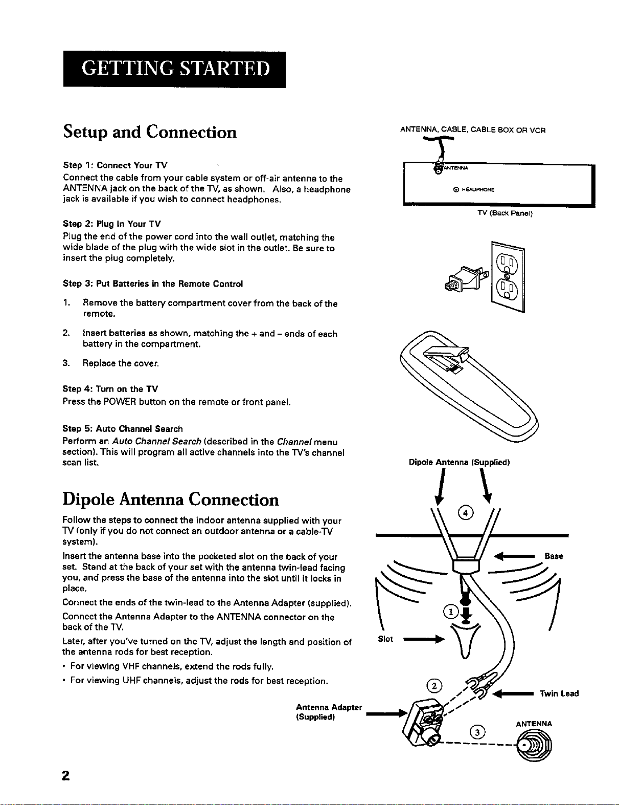
Step 1: Connect Your TV
Connect the cable from your cable system or off-air antenna to the
ANTENNA jack on the back of the "iV,as shown. Also, a headphone
jack is available if you wish to connect headphones.
Step 2: Plug In Your TV
Plug the end of the power cord into the wall outlet, matching the
wide blade of the plug with the wide slot in the outlet. Be sure to
insert the plug completely.
Step 3: Put Batteries in the Remote Control
1. Remove the battery compartment cover from the back of the
remote.
2. Insert batteries as shown, matching the + and - ends of each
battery in the compartment.
3. Replace the cover.
Step 4: Turn on the TV
Press the POWER button on the remote or front panel.
ANTENNA, CABLE, CABLE BOX OR VCR
"IV (Back Panel)
Step 5: Auto Channel Search
Perform an Auto Channel Search (described in the Channe/menu
section). This will program all active channels into the TV's channel
scan list.
Dipole Antenna Connection
Follow the steps to connect the indoor antenna supplied with your
"IV (only if you do not connect an outdoor antenna or a cable-TV
system).
Insert the antenna base into the pocketed slot on the back of your
set. Stand at the back of your set with the antenna twin-lead facing
you, and press the base of the antenna into the slot until it locks in
place.
Connect the ends of the twin-lead to the Antenna Adapter (supplied).
Connect the Antenna Adapter to the ANTENNA connector on the
back of the TV.
Later, after you've turned on the TV, adjust the length and position of
the antenna rods for best reception.
• For viewing VHF channels, extend the rods fully.
• For viewing UHF channels, adjust the rods for best reception.
Antenna Adapter
(Supplied)
Slot
DipoleAntenna (Supplied)
!\
®
®
Base
Twin Lead
ANTENNA
® .@
2
Page 5
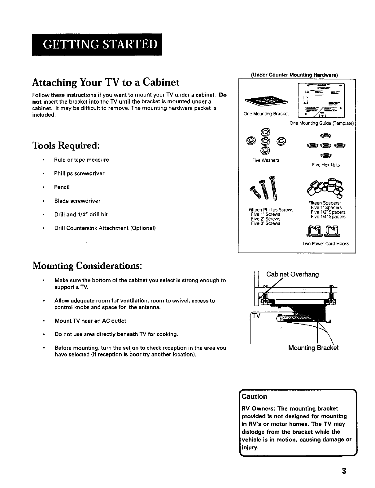
Attaching Your TV to a Cabinet
Follow these instructions if you want to mount your'IV under a cabinet. Do
not insert the bracket into the "IV until the bracket is mounted under a
cabinet. It may be difficult to remove. The mounting hardware packet is
included.
Tools Required:
(Under Counter Mounting Hardware)
OneMountingBracket ÷
OneMountingGuide(Template)
Rule or tape measure
Phillips screwdriver
Pencil
Blade screwdriver
Drill and 1/4" drill bit
Drill Countersink Attachment (Optional)
Mounting Considerations:
Make sure the bottom of the cabinet you select is strong enough to
support a "iV.
Allow adequate room for ventilation, room to swivel, access to
control knobs and space for the antenna.
Mount "IV near an AC outlet.
Do not use area directly beneath TV for cooking.
Five Washers
FifteenPhillips Screws:
Five1" Screws
Five2"Screws
Five3"Screws
Cabinet Overhang
FiveHexNuts
Fifteen S acers:
Five1"_pacers
Five 112"Spacers
Five114"Spacers
Two Power Cord Hooks
Before mounting, turn the set on to check reception in the area you
have selected (if reception is poor try another location).
Mounting
Caution
RV Owners: The mounting bracket
provided is not designed for mounting
in RV's or motor homes. The TV may
dislodge from the bracket while the
vehicle is in motion, causing damage or
injury.
3
Page 6
Mounting Instructions:
1. Prepare cabinet
Remove items from counter and cabinet.
Clean underside of cabinet where "iV is to be mounted.
2°
Cut out the mounting guide and screw guide
Cut out the guides on the lines indicated.
The size of the mounting guide and the screw hole positions
are identical to the top of the mounting bracket.
3,
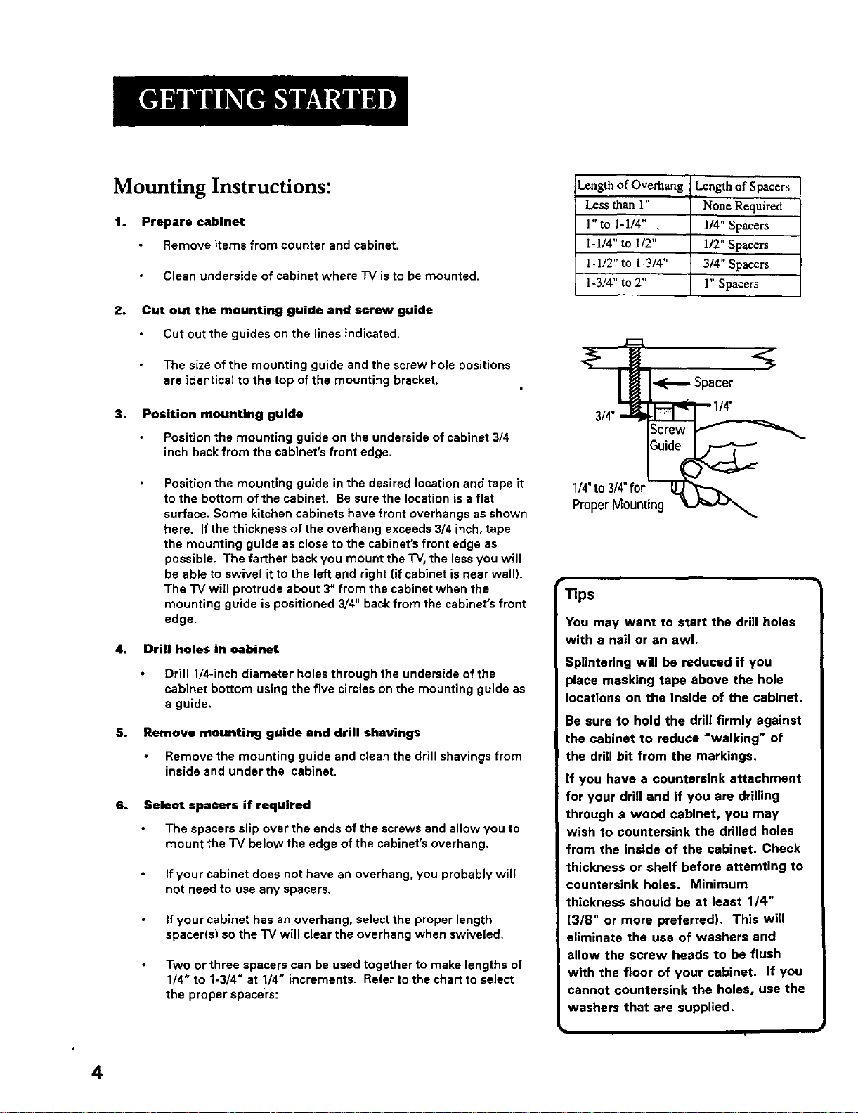
Position mounting guide
Position the mounting guide on the underside of cabinet 3/4
inch back from the cabinet's front edge.
Length of Overhang
Less than 1"
1" to 1-1/4"
I-1/4" to 1/2"
1-1/2" to 1-3/4"
1-3/4" to 2"
--Spacer."%
Length of Spacers
None Required
114" Spacers
1/2" Spacers
3/4" Spacers
l" Spacers
Position the mounting guide in the desired location and tape it
to the bottom of the cabinet. Be sure the location is a flat
surface. Some kitchen cabinets have front overhangs as shown
here. If the thickness of the overhang exceeds 3/4 inch, tape
the mounting guide as close to the cabinet's front edge as
possible. The farther back you mount the TV, the less you will
be able to swivel it to the left and right (if cabinet is near wall).
The "IV will protrude about 3" from the cabinet when the
mounting guide is positioned 3/4" back from the cabinet's front
edge.
4. Drill holes in cabinet
Drill 1/4-inch diameter holes through the underside of the
cabinet bottom using the five circles on the mounting guide as
a guide.
5.
Remove mounting guide and drill shavings
Remove the mounting guide and clean the drill shavings from
inside and under the cabinet.
6°
Select spacers if required
The spacers slip over the ends of the screws and allow you to
mount the "IV below the edge of the cabinet's overhang.
If your cabinet does not have an overhang, you probably will
not need to use any spacers.
If your cabinet has an overhang, select the proper length
spacer(s) so the "IV will clear the overhang when swiveled.
Two or three spacers can be used together to make lengths of
1/4" to 1-3/4" at 1/4" increments. Refer to the chart to select
the proper spacers:
1/4' to 314"for -_'_:_"_"
Proper Mounting
Tips
You may want to start the drill holes
with a nail or an awl.
Splintering will be reduced if you
place masking tape above the hole
locations on the inside of the cabinet.
Be sure to hold the drill firmly against
the cabinet to reduce =walking" of
the drill bit from the markings.
If you have a countersink attachment
for your drill and if you are drilling
through a wood cabinet, you may
wish to countersink the drilled holes
from the inside of the cabinet. Check
thickness or shelf before attemting to
countersink holes. Minimum
thickness should be at least 1/4"
(3/8" or more preferred). This will
eliminate the use of washers and
allow the screw heads to be flush
with the floor of your cabinet. If you
cannot countersink the holes, use the
washers that are supplied.
4
Page 7
7.
Select proper length of screws
Only five screws are needed. The size you need depends upon
your type of cabinet.
Holding the selected spacers for one of the screw holes under the
cabinet, install a washer and screw inside the cabinet using one of
the three lengths of screws provided. A visual description of these
parts is on page 3.
8°
Position mounting bracket under cabinet
Position the mounting bracket under the cabinet as shown and
match the screw holes.
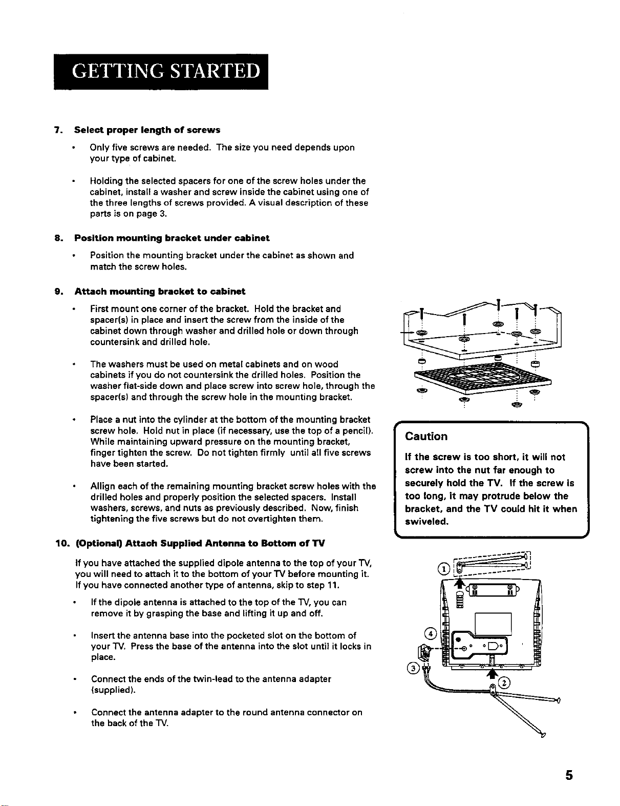
9. Attach mounting bracket to cabinet
First mount one corner of the bracket. Hold the bracket and
spacer(s) in place and insert the screw from the inside of the
cabinet down through washer and drilled hole or down through
countersink and drilled hole.
The washers must be used on metal cabinets and on wood
cabinets if you do not countersink the drilled holes. Position the
washer fiat-side down and place screw into screw hole, through the
spacer(s) and through the screw hole in the mounting bracket.
Place a nut into the cylinder at the bottom of the mounting bracket
screw hole. Hold nut in place (if necessary, use the top of a pencil).
While maintaining upward pressure on the mounting bracket,
finger tighten the screw. Do not tighten firmly until all five screws
have been started.
Allign each of the remaining mounting bracket screw holes with the
drilled holes and properly position the selected spacers. Install
washers, screws, and nuts as previously described. Now, finish
tightening the five screws but do not overtighten them.
Caution
If the screw is too short, it will not
screw into the nut far enough to
securely hold the TV, If the screw is
too long, it may protrude below the
bracket, and the TV could hit it when
swiveled.
10. (Optional) Attach Supplied Antenna to Bottom of TV
If you have attached the supplied dipole antenna to the top of your "IV,
you will need to attach it to the bottom of your "IV before mounting it.
If you have connected another type of antenna, skip to step 11.
If the dipole antenna is attached to the top of the "IV, you can
remove it by grasping the base and lifting it up and off.
Insert the antenna base into the pocketed slot on the bottom of
your "IV. Press the base of the antenna into the slot until it locks in
place.
Connect the ends of the Wvin-lead to the antenna adapter
(supplied).
Connect the antenna adapter to the round antenna connector on
the back of the "IV.
r--_
5
Page 8

Later, after you have turned on the TV, adjust the length and
position of the antenna for best reception.
• For viewing VHF channels 2-13, extend the rods fully.
• For viewing UHF channels 14-69, shorten the rods for best
reception.
• For listening to the radio, if necessary, adjust the antenna rods for
best reception.
11. Slide TV onto Bracket
The "iV must be slightly below the cabinet overhang when installed in
the bracket. Some clearance is necessary so the TV can be easily
rotated to the desired viewing angle or removed for portable use.
Slide the TV onto the mounting hook of the bracket and push it all
the way back until the hook on the bracket locks into the back of the
"IV.You should hear the "iV click into place.
Secure the TV in the bracket by sliding the locking tab on the back
of the bracket into the bracket assembly.
To remove the rv, slide the locking tab out of the bracket assembly.
Lift the TV up and gently pull forward.
12. Attach AC Power Cord
First attach the AC power cord to the 4-prong connector on the
back of the "IV.
Then extend the cord and plug it into an electrical outlet.
13. Attach Cord Hooks
You can use the cord hooks to hold the cord out of the way.
For the most attractive appearance, place the cord hooks at the
back edge of the cabinet (on or next to the wall) directly above the
outlet to be used.
To attach the cord books, peel off the adhesive back and attach the
hooks to a clean, dry surface on underside of cabinet or back wall.
Use the cord tie that is attached to the power cord to wrap and tie
excess cord out of sight.
Warning
Make sure the locking slide is pushed
fully into the locked position. Failure
to lock the sliding tab into position
may allow the TV to fall off the
barcket causing personal injury or
damage to the TV. Push the eliding
tab into the bracket assembly until
you hear a click.
6
Page 9

Channel Marker
The Channel Marker comes up when you first turn on the "r'v,change
channels, or press the DISPLAY button.
01.'30 Displayed to count down time left on the commercial skip timer.
13 Displays the current channel.
7;17 Displays the current time.
CC Displayed when Closed Captioning is available.
Mute Displayed when you mute the audio.
Sleep Displayed when the Sleep "rimer has been set.
Front Panel Controls
CHAN ^ Scans up through the channel list. When a menu is displayed,
CHAN ^ points up to items and adjusts menu controls.
CHAN v Scans down through the channel list. When a menu is displayed,
CHAN v points down to items and adjusts menu controls.
MENU Brings up the Main menu. When in the menu system, it selects
highlighted items. Also returns you to the previous menu.
POWER Turns the "IV on and off.
VOL - Decreases the volume. When a menu is displayed, VOL- is used
to point left to items and adjust menu controls.
VOL + Increases the volume. When a menu is displayed, VOL + is used
to point right to items and adjust menu controls.
7:17 13
Sleep CC
Mu_e 1:30
The Channel Marker shown is just an example
of what your screen may look like.
You can press MENU or CLEAR to
make the Channel Marker disappear,
or it will disappear automatically
after a short time.
Front Panel Lock
This feature allows you to lock the buttons on the front of the "IV. Even
when the front panel lock feature is ON, the "IV operates with the remote
control.
• To lock the buttons on the front of the "IV, make sure the TV is turned
ON, then press and hold the POWER button on the remote for
approximately 5 seconds.
• To turn off the front panel lock, make sure the "IV is OFF, then press
and hold the POWER button on the remote for approximately 5
seconds. Now the buttons will operate properly.
Caution
If you choose to use a stand with
your TV. take precautions that the
stand or other furniture the TV is
placed on is properly located and of
adequate size and strength to
prevent the TV from accidentally
being pushed off, pulled off, or
tipped over. This could cause
damage to the TV and/or personal
injury.
7
Page 10

Remote Control Buttons
When operating the remote, point it directly at the front of the "IV.
Objects between the remote and the remote sensor can block the signal to
the "IV.
POWER Button Press to turn the "iV on or off.
PREV CH Button (Previous Channel) Pressing this button switches the
"IV back to the last tuned channel. This is useful if you want to watch two
channels. Select the first channel you wish to watch. Then select the other
channel by pressing two number buttons. The "IV changes back and forth
between the two channels each time you press this button.
DISPLAY Button Press to display the time and channel number on the
screen. Press to see if the Sleep 1]mer, Alarm "rimer, and Closed Captioning
are set. Press to quickly remove menus from the screen unless otherwise
noted within the menu.
MUTE Button Press to quickly reduce sound to minimum level. Closed
captioning (C1) may appear on the screen when you press MUTE. To
restore sound and normal picture, press MUTE again or press VOL up.
CHAN ^Iv Buttons (Channel Up and Down) Press to select the next
higher or lower channel in memory. You can add or erase channels in
memory as desired. Details are on page 10. When a menu is displayed,
CHAN ^/vallows you to select and adjust menu controls.
VOL Buttons (Volume Up and Down) (Also - and + Buttons) Press
VOL + to increase volume, or press VOL - to decrease volume. The volume
display appears on the screen when you press the VOL buttons. When a
menu is displayed, press + or- to adjust the setting of an item that is
highlighted in a menu.
MENU Button Brings up the Main menu. When in the menu system, it
selects highlighted items. Also returns you to the previous menu.
RESET Button Press to return all video settings (color, tint, contrast,
brightness, and sharpness) back to the original settings.
CLEAR Button Press to clear the screen of all on-screen displays.
Number Buttons (0.9) Press to directly access any channel number. To
select a channel, press two number buttons. For example, press Othen 6
for channel 6. To select a 3-digit number, press and hold number button 1
until 1- appears on the screen. Then press the other two numbers.
INPUT Button Switches the TV to channel 3. This is useful if you have a
VCR connected to your"iV.
SKIP Button (Commercial Skip) Press to operate Commercial Skip
during "IV viewing.
POWER
CHAN
CLEAR MENU RESET
0 IKI
0oo
o0bb
5O5
Point and Select
To use the on-screen menus, you
need to know one rule: point and
select:
• Point to your selection with the
on-screen highlight. (Use the
Vol +/- buttons on your remote
to move left and right; use the
CH A/v buttons to move up and
down.)
• Press the MENU button to select
the highlighted item.
8
Page 11

TV Main Menu
The TVMain Menu isyour gateway to controlling the "IV. It lets you adjust
the TV's picture quality, screen, channel settings, parental controls, and
time functions.
To select a menu item:
1. Press MENU to bring up the 7"VMain Menu.
2. Use the CHAN ^/v on the remote or front of TVto highlight an item
and press MENU to select it; or you can also press the
corresponding number on the remote.
3. To exit any menu screen, highlight Exit and press MENU, or press
CLEAR on the remote.
The Picture Quality Menu
The Picture Qua/ity Menu contains five controls that adjust the TV's picture.
Use the VOL +/- and CHAN ^/v buttons to adjust the controls.
Contrast Adjusts the difference between light and dark areas of
the picture.
Color Adjuatsthe richness ofthe color.
"l_nt Adjusts the balance between the red and green levels allowing
you to get the correct fleshtones.
Black Level Adjusts the brightness of the picture.
Sharpness Adjusts the crispness of edges in the picture.
Reset Picture Controls Resets the picture controls to their
original settings.
TV Main Menu
1 Picture Quality
2 Screen
3 Channel
4 V-ChipParentalControls
5 11ms
0 Exit
The TV Main Menu
Picture Quality Menu
1 Contrast +...,...i........-
2 Color +,__..L.._...-
3 Trot ÷......L...,-
4 8kLckl.evsl +....,..L......-
5 _ss ÷..;..._L__...-
6 Reset Plc_re ,3_trols
7 Exit
The Picture Qua/ity Menu
Tip
You can also use the RESET button
on the remote at any time to reset
the picture controls to their original
settings.
]
The Screen Menu Screen
The Screen menu contains the controls that let you adjust the Closed-
Caption display, Closed-Caption mode, and Menu Language. " 3_!
CC (Closed.Caption) Display Lets you choose the way closed captioning 0
information is shown on the screen. Use the MENU button to toggle The Screen menu
between the following:
Off No captioning information displayed.
On Captioning information shown always, when available.
On When Muted Displays captioning information, when available,
whenever you press the MUTE button. The captioning information is
not displayed when the sound is not muted.
CC (Closed.Caption) Mode Lets you choose which captioning mode is
used for displaying captioning information. Use the MENU button to toggle
between the choices: CC1 and CC2.
Not all programs are encoded with closed-captioning information. When a
program is closed captioned, the letters CC are displayed under the Channel
Marker.
Menu Language Lets you select the language of your choice: English,
French, or Spanish. Use the MENU button to toggle between the choices.
Closed Caption Modes
CCl : full translation of the primary
language in your area
CC2: secondary language
translation, simplified English, or
whatever is being broadcast in your
area
9
Page 12

The Channel Menu
The Channel menu contains all the commands used to control your
channels, including custom-building your channel list.
Signal Type Displays a toggle that lets you select the current antenna
type:
Antenna Choose this if you are currently using an off-air antenna
for UHF/VHF TV signals.
Cable TV Choose this if you ere currently using cable or a cable
box for TV signals.
Auto Channel Search Selecting this option tells the TV to search
automatically for all the channels available through the antenna input.
When the "IV finds an active channel, it places it in the channel list. Inactive
channels (weak stations or channels with no signal at all) will be removed
from the channel list. (You may interrupt this process by pressing the MENU
button.)
List Displays a control panel that lets you customize your channel scan list
by adding or removing channels. Use the VOL +/- buttons to move left and
right between fields; use the CHAN ^A' buttons to enter settings. Press
MENU to exit.
Channel Number Use the CHAN ^/v buttons to scroll through the
channel scan list. You can a{so enter the channel number directly
using the number buttons.
Scan List Indicates whether the channel number is included (YES) or
is not included (NO) in the channel scan list.
Channel
1 SignalType:
2Auto ChannelSearch
$ List
0 Exit
The Channel menu
List
;c_n
CABLE "IV
/i!i¸i i!i!i!!ili i!!
V-Chip Parental Controls
The V-Chip Parental Controls menu allows you to program your "iVso that
children cannot see certain programs. When you select V-Chip Parental
Controls, you will be prompted to enter your password if controls are
locked, or to remember to lock controls if unlocked,
The first three choices in the Parental Controls menu involve software
inside your "IV (dubbed V-Chip) which allows you to block "IV programs and
movies based on violence, sex, or other content you believe children should
not view. Once you block programs, you or other adults can unblock
programs with a password.
When turned "on," the software reads a code that most broadcasters send
with programs. That code tells the V-Chip the program's age-based rating
and content themes. If you have blocked the rating or content themes that
the program contains when you tune to that program, you will receive the
message, "This program is blocked, Change channel or press DISPLAY to
enter password."
Broadcasters are not required to provide content themes or age-based
ratings. Rated programs received with no content themes will only be
blocked if you block their age-based rating. You can also block movies with
a rating of "Not Rated" and "unrated" TV programs.
List menu
TV Main Menu
0 i_F_xtt
Setting V-Chip Parental Controls
IiThe V-Chip software inside your TV I
comes turned "off," so if you choose to |
mplement it, you must turn it on. )
10
Page 13

V-Chip Movie Rating Limit
With the Movie Rating Limityou can set movie-viewing limits.
Blocking Movie Ratings
You can automatically block all movie ratings above a specified rating using
Movie Ratings Limit in the Parental Controls menu.
• To block all movies above a certain rating: In the Rating field,
use CHAN ^/v to highlight the lowest unacceptable rating. Then
highlight the Rating Status field and press the CHAN ^/v buttons to
change the status from Viewto Block. All higher ratings will
automatically change to Block.
• To leek ]four seleotion(s): Select Parental Contro/sfrom the
Parental Controls menu. Press the VOL + to select LOCKED. Enter
your password (if you have not already set your password, you will be
prompted to enter it again to confirm). The word UNLOCKED will flash
to remind you that the Parental Controls are not LOCKED.
V-Chip Parental Controls
1 Movie RatingLimit
2 TV RatingLimit
3 UnratedPrngrems: VIEW
4 ParentalControls: UNLOCKED
O Exit
Selecting Movie Rating Limit
Rating
field Rating Status field
Rating
Viewing Movie Ratings
After you block movie ratings, you have the option of changing some of the
ratings back to View.
• To view movie ratings: Highlight the Rating field and use the
CHAN ^/v buttons to find the rating you want to view. Then use VOL +
to highlight the Rating Status field, and use CHAN ^/v to change the
status to View.
V-Chip TV Rating Limit
The V-Chip "IV Rating Limit lets you decide which "IV programs can be
viewed. To set "IV programming limits:
1. Choose V-Chip Parental Contro/sfrom the Main menu. If Parental
Controls have previously been locked, you must enter your
password. If they are not locked, you will get a message reminding
you that your limits will not be effective until you lock Parental
Controls.
2. Press MENU to continue.
3. Highlight and select TVRating Limit.
4. Once you get to the "IV Rating Limit screen, use the CHAN ^/v and
VOL +/- on your remote to change the status of a "iV program rating
or content theme from Viewto Block.
The following sections give you more details about how to change the
status of "iV program limits.
PressMENUtOexit.
Viewing movie ratings
V-Chip Parental Controls
Selecting TV Rating Limit
TIP
When you change the status of an
age-based rating to Block, the
system will automatically block
that rating and all of its content
themes and all higher ratings and
their content themes. When you
change the status of a Content
Theme to B, the system will
automatically block that content
theme in the current rating and in
; all higher ratings. Only the content
theme status corresponding to the
current age-based rating changes
to View (V). Higher rated content
themes do not change.
i
11
Page 14

The TV Rating Limit Screen
Below is an example of where items are tocated within the TV Rating
Limits screen.
Rating field Content Themes
Letsyou selectfrom a listof Liststhe contentthemesyou
age-basedratingsyou can TV Rating Limit
blockorview. _
r31p
You can always press MENU to exit
back to the previous screen while in
the Rating Limit menus.
/ can blockor view.
Content /
sta ,. IDL sv I contentstatusfields
......... J' v v v I Letsyouselectwhichcontent
vomser i.ilgnngnt I \ _themestoviewforthe selected
Letsyou seethe positionof _- _ i_ _ _ting, andwhetherthe statusof
the cursoron the screen. Press MENU to _lx_t. _ t_e content theme is currently
i
Rating Status field
Letsy0u selectwhether the statusofthe
The TV age-based ratings and content themes you can block are listed in age-basedrating limitto the left isViewer
the table below. B/ock.
Age-Based
Rating Description and Content Themes for Age-Based Ratings
TV-MA Mature Audience Only. Specifically designed to be viewed by adults and may be unsuitable for
children under 17. Itcontains one or more of the following content themes: graphic violence (3/),
explicit sexual activity (S), or crude indecent language (L).
TV-14 Parents Strongly Cautioned. Contains some material that many parents would find unsuitable for children
under 14. Parents are strongly urged to exercise greater care in monitoring this program and are cautioned
against letting children under the age of 14 watch unattended. This program contains one or more of the
following content themes: intense violence (V), intense sexual situations (S), strong coarse
language (L), or intensely suggestive dialogue (D).
TV-PG Parental Guidance Suggested. Contains material that parents may find unsuitable for younger children.
Many parents may want to watch it with their younger children. The program contains one or more of the
following content themes: moderate violence (V), some sexual situations (S), infrequent coarse
language (L), or some suggestive dialogue (D).
"I'V-G General Audience. Most parents would find this program suitable for all ages. It contains little or no
violence (V), sexual situations (S) no strong language, (L) and little or no sexual dialogue (D).
TV-Y7 Directed to Children 7 years and older. Designed for children ages 7 and above. It may be more appropriate
for children who have acquired the developmental skills needed to distinguish between make-believe and
reality. Themes and elements in this program may include mild fantasy violence (FV) or comedic violence,
or may frighten children under the age of 7.
rv-Y All Children. Themes and elements in this program are designed for a young audience, including children
from ages 2-6. It is not expected to frighten younger children.
View (V)or Block(B).
12
Page 15

Blocking Age-Based Ratings and Content Themes
You can automatically block all program ratings or content above a
specified age-based rating level using the V-Chip TVRating Limitscreen.
Refer to the chart at the beginning of this section to learn about each age-
based rating and its associated content ratings.
• To block all programs above a certain rating level: Highlight
the Rating field, then scroll through the ratings using the CHAN ^_
buttons until the lowest unacceptable rating is highlighted. Then use
the VOL + button to highlight the Rating Status field and select Block.
• To block all programs with specific content above a certain
rating level: Content Themes are specific to the rating level.
Therefore, you must first highlight the Rating field and scroll through
the ratings using the CHAN ^/v buttons until the lowest rating
associated with the type of content you want to block is highlighted.
Then highlight the Content Theme Status field and change the V to B
under the appropriate Content Theme.
Viewing Age-Based Ratings and Content Themes
After you have b{ocked age-based ratings and content themes, you have
the option of selectively changing some of the ratings and themes back to
View.
• To view ratings: Use the VOL +/- buttons to highlight the Rating
Field, then use CHAN ^/_ to change its status from Block to View.
When you change a specific rating to View, the Content Status fields
corresponding to the unblocked rating become View as well.
• To view content: Highlight the Rating field, then use CHAN ^/v to
find the rating whose Content Theme settings you want to change.
Next, highlight the Content Theme Status that you want to change
using the VOL + button; then use CHAN ^/v to change it to V.
Rating field
Rating Status
TV-14 Block
Content Themes
TV Rating Limit {
Content
DLSVFV
VVVV
I
I
Z::::::,.,0
Content Themes
Status field
B/ocking age-based ratings and content themes
Rating field Content Themes
1 TV Rating Limit I
TV_ View V BVV
Cordent
v
Rating Status field Content Themes
Viewing age-based ratings and content themes
Status field
screens, pressing RESET on the
remote will reset all ratings to View
I While within the Rating Limit 1
and V.
Overriding Limits
When you override a blocked
program by entering your password,
the Parental Controls option on the
V-Chip Parental Controls menu will
read Disabled. In this state, access
to the Parental Controls menu is still
locked and all controls will be in
effect the next time the TV is turned
on.
13
Page 16

V-Chip Unrated Program Block
Selecting this option lets you decide if programs that the V-Chip recognizes
as "unrated" can be viewed.
View All unrated programs are available.
Block No unrated programs are available.
"Unrated" "IV programs may include news, sports, political, religious, local,
and weather programs, and public announcements. Also, the first few
seconds of a channel with rated programming may be blocked (due to a
brief delay in transmission of the rating information).
Lock/Unlock Parental Controls
Selecting this option lets you lock and unlock parental controls settings
using a password.
You must lock Parental Controls for TV rating and content, movie
rating, and unrated program blocks to take effect.
If you forget your password, the password can be reset to O000 by pressing
and holding the volume down and the channel up buttons simultaneously
for five seconds, Using this password, you can then access the V-chip
menus.
The Time menu
"Unrated" vs. "Not Rated"
All movies are assigned a rating.
Some movies are given a rating of
Not Rated (NR). You can assign
Block or View status to the NR
rating in the V-Chip Movie Rating
Limit screen.
Not all television programs are
assigned a rating (age-based rating).
To assign View or Block status to
Uunrate d u television programs, you
must use the Unrated Programs
option from the V-Chip Parental
Controls menu.
tl
When you want to watch a blocked
program, press the DISPLAY button on
Remember 1
the remote to enter your password.
The "time menu contains the controls that let you set the Sleep -timer, Set
-time, and Wake-up "fimerfunctions.
Sleep "nmcr Displays a control panel that lets you select the
amount of time you want to give the "IV before it shuts itself off.
Use the VOL ÷/- buttons to increase or decrease the sleep timer by 30
minute increments. Press MENU to exit.
Set "nine Displays a control panel that lets you enter the current
time. Use the VOL +/- buttons and number buttons to set the time.
Press MENU to exit.
Wake-up "nmer Displays a control panel that lets you enter the
time you wish your television to turn itself on. Use the VOL ÷/-
buttons to set the wake-up timer. To clear the wake-up timer, display the
wake-up screen and press RESET.
Time
The .time menu
14
Page 17

Commercial Skip
As its name suggests, Commercial Skip allows you to bypass commercials
during normal TV viewing. When a commercial comes on, you can activate
the Commercial Skip timer to run from 30 seconds to 4 minutes. While the
timer is counting down, you are free to watch other channels, After the
timer runs out, the "IV automatically changes back to your original channel.
Use the following steps to program the Commercial Skip timer:
1. On your remote, press SKIR An on-screen timer appears,
2. Press SKIP repeatedly to set the timer as desired. The time increases
by 30 seconds each time SKIP is pressed. Skip countdown starts
automatically if you haven't pressed SKIP for two seconds.
3. To cancel Commercial Skip, keep pressing SKIP until the SKIP
display disappears from the screen, or press CLEAR. Your TV will
stay tuned to the channel it is on and will not change back to your
original channel.
15
Page 18

If you experience any difficulty with your "IV,check these basic remedies
before calling your service technician.
TV will not turn on or controls don't work
• Check to make sure it is plugged in.
• Check the wall receptacle (or extension cord) to make sure it is _live"
by plugging in something else.
• Try unplugging set for one minute, plugging it back in, and then
turning it on again.
• Make sure the Front Panel Lock feature is not set. (See page 7 for
details.)
Problems with remote
• Maybe something is between the remote and the remote sensor.
• Maybe the remote is not aimed directly at the TV's remote sensor.
• Maybe batteries in remote are weak, dead or installed incorrectly. Try
replacing batteries.
Turns on or off while playing
• Electronic protection circuit may have been activated because of a
power surge. Wait 30 seconds and then turn on again. If this happens
frequently, the voltage in your house may be abnormally high.
• Maybe the Sleep _mer or Alarm Timer is activated.
Blank screen or black box appears on the screen
• Try another channel.
• Press RESET, in case the picture controls are set too low.
• Captioning may be turned on. Checkthe Closed-Caption Display
control panel in the Screen menu.
No sound, picture okay
• Maybe sound is muted. Try pressing volume up button to restore
sound.
16
Page 19

No picture, no sound, but power is on
• Maybe cable/air function is in wrong position. Try another channel.
• Maybe a vacant channel is tuned. Try another channel.
Sound okay, picture poor
• Check antenna connections.
• Try adjusting sharpness function to improve weak signals.
17
Page 20

What your warranty covers:
• Any defect in materials or workmanship.
For how long after your purchase:
• 90 days for labor charges.
• One year for parts.
• Two years for the picture tube.
The warranty period for rental units begins with the first rental or 45 days from date of shipment to the rental firm, whichever comes first.
What we will do:
• Pay any Authorized GE Television Service Center the labor charges to repair your television.
• Pay any Authorized GE Television Service Center for the new or, at our option, refurbished replacement par_s and picture tube required
to repair your television.
How you get service:
. For screen sizes of 26" and smalle_ Take your GE television to any Authorized GE Television Service Center and pick up when repairs
are complete.
• For screen sizes larger than 26": Request home service from any Authorized GE Television Service Center, provided that your television
is located within the geographic territory covered by an Authorized GE Television Service Center. If not, you must take your television
to the Service Center location at you r own expense, or pay for the cost the Service Center may charge to transport your television to
and from your home.
• To identify your nearest Authorized GE Television Service Center, ask your dealer, took in the Yellow Pages, or call 1-800-447-1700.
• Show the Authorized Service Center Representative your evidence of purchase date or first rental.
What your warranty does not cover:
• Customer instruction. (Your Owner's Manual clearly describes howto install, adjust, and operate your television. Any additional
information should be obtained from your dealer.)
• Installation and related adjustments.
• Signal reception problems not caused by your television.
• Damage from misuse or neglect.
• Batteries.
• Customer replacement fuses.
• Images burnt onto the screen.
• A television that has been modified or incorporated into other products or is used for institutional or other commercial purposes.
• Ate[evision purchased or serviced outside the U.S.A.
• Acts of God, such as but not limited to lightning damage.
Product Registration:
• Please complete and mail the Product Registration Card packed with your TV. it will make it easier to contact you should it ever be
necessary. The return of the card is not required for warranty coverage.
How state law relates to this warranty:
• This warranty gives you specific legal rights, and you also may have other rights that vary from state to state.
18
Page 21

Remote Control
This is the remote that came
packed with your TV. You can use
the order form to order it direct by
mail if desired.
Accessory Order Form
Description
Transformer VH54 $ 2.95
Cleaner/Polisher AH035 $ 6.95
Total
Optional Remote
This remote not only controls
your "IV but can also control most
brands of remote-controllable
VCR's, cable boxes, and audio
equipment.
Dipole Antenna
Designed to attach to the back of
your "IV. Can be used for both
VHF and UHF channels.
Antenna Cables
Screw-on Antenna Cable
Attaches to the round antenna
connectors (called 75-ohm F-type)
on the back of your VCR or "IV.
The ends screw onto the
connectors for a secure
connection.
231032
RCU500
156265
VH81 (3-ft)
Screw-on Antenna Cable (3-ft) VH81 $ 3.95 i
A/B Switch AH041 $14.95
Gold-Tipped Antenna Cable (6-ft) VH89 $ 5.95
Gold-_pped Antenna Cable (!0-ft) VH90 $ 7.95
Optional Remote Control RCU500 $19.95
Dipole Antenna 156265 $11.15
Antenna Adapter 193983 $ 9.90
Antenna Mixer 193984 $11,15
Replacement Remote Control (CRK20A1W) 231032 $34.45
TotalMerchandise..........................................$
SalesTax ...........................................................$
We are required by law to collect the appropriate
sales tax for each individual state, county, and
locality to which the merchandise is being sent.
Shipping, Handling ........................................
Total Amount Enclosed ..................................
$__
Push-on Antenna Cable
Attaches to the round antenna
connectors (called 75-ohm F-type)
on the back of your VCR or"iV.
Ends push on for a quick
connection.
Gold-31pped Cables ,_,
VH89 (6-ft),VHgO(lO-ft) _
Note: ALLspecifications and descriptions of accessories
are subject to change without notice.
Use VISA, MasterCard or Discover Card preferably
Money order or check must be in U.S. currency only.
No COD or CASH.
Prices are subject to change without notice.
All accessories are subject to availability.
t_
PleaseComplete Other SideAlso
19
Page 22

Charge your order on your VISA,
MasterCard, or Discover Cardby
filling in below
USE YOUR CREDIT CARD
IMPORTANT: Copy complete account number
from your VISA card
VISA"
Placing An Order
To place your order by phone, have your Visa, MasterCsrd
or Discover Card ready and call the toll-free number listed
below. Use this number only to place an order for
accessory items listed on this order form.
1.800-338-0372
N-]-T-111111[IIFT-[-1
My card expires: [--I-7
IMPORTANT: Copy complete account number
from your MastetCard
r-r-r- r-rT-N
Copy Number
above your
[lam_ on
MasterCard
IMPORTANT: Copy complete account number
from your Discover Card
MYc_dl I II 1 I
exptres:
r-z-r-rqr-T-r-rqN-r-rq
My cardexpires: ['-T-]
AUTHORIZED SIGNATURE
(Credit card order will not be processed without signature)
Print or type year name and A complete and correct
address clearly, order will save you days
of waiting.
To place your order by mail, detach and mail the
completed order form with credit card information, money
order or check in US currency (made payable to Thomson
Consumer Electronics, Inc.) to the following address:
Video Accessories
PO Box 8419
Ronks, PA 17573
Nanlg:
S_'eet:
Apt:
City:
State: Zip:
Daytime Phone Number:
Please make sure that both sides of this form ,"
have been filled out completely.
• Allow 4 weeks for delivery.
• All accessories are subject to availability, ti
• Prices are subject to change
20
A
Page 23

Please do not send any products to the Indianapolis address listed in this manual or on the carton. This will only add
delays in service for your product.
f_ THOMSON CONSUMER ELECTRONICS
10330 North Meridian Street
Indianapolis, IN 46290
©2000 Thomson Consumer Electronics, Inc.
Trademark(s)® Registered
Marca(s) Registrada(s)
Printed in the U.S.A.
TOCOM 15552000
MODEL #:
09GP344
15552000
 Loading...