

Page 1
THE R MA L E R T®C I
™
C OMPAC T INFR A R E D
S E N S OR
OP E R ATO R ’ S G U IDE
T WO Y EA R LI M IT ED WA RR A N T Y
R aytek warr ants thi s prod uct to be free f rom d efects i n materi al and
wor k man shi p u nder nor mal u se an d s erv ice f or a per iod of two
year s f rom date of p urchase except as herein after pr ovi ded. T his
warr anty extend s on ly to the ori gin al pur chaser ( a pu rch ase fr om
R ay tek or R aytek ’ s l icensed di str ibutors is an ori ginal p urch ase).
This w arranty shall not appl y to fu ses or batteries. Factory calibr ation is wa rr anted for a peri od of one year. T he war ran ty shal l not
appl y to any prod uct w hich has been subject to m is use, neglect,
accident, or abnor ma l con ditions of op erati on or stor age. Should
R ay tek be u nabl e to repair or r eplace th e product withi n a reason able am ount of time, p urchas er’s exclu sive remedy shall be a refu nd
of the pur chase pri ce upon retu rn of th e prod uct.
In the event of fail ure of a produ ct covered by this war ranty, R aytek
wi ll r epair th e ins tru ment w hen it is retur ned by the pu rchaser,
frei ght prepai d, to a n author ized Servi ce Facil ity w ithi n the appl icable w arran ty peri od, pr ovided Ray tek’ s exami nation d iscloses to its
satis facti on that the pr odu ct w as defectiv e. R ay tek m ay, at its
option, repla ce the produ ct in l ieu of repair. W ith regar d to any covered p rodu ct r eturn ed w i thin the ap pli cable wa rr anty period ,
repai rs or replacem ent wi ll be m ade w ithout cha rge and w ith return
frei ght pa id by R ay tek, u nless the f ail ur e w as ca used by mi sus e,
neglect, a ccident, or abnorma l condi tions of operation or storage, in
wh ich case r epairs wil l be bil led at a reasonable cost. I n such a case,
an esti mate wi ll be su bmitted before w ork is started, if requested.
T HE F OR EG O IN G WA R RA N T Y I S I N L IE U OF AL L OT H E R WA RR A N T IE S, E XPR E S SE D O R IM PL IE D, I N C L U D I N G BU T N OT
L IM IT E D T O A NY I MP LI ED WA R RA N T Y O F M ER CH A N TA BIL IT Y, FI TN E SS, O R A D EQ UA C Y F OR AN Y PA RT IC U LA R PU RP OSE
OR US E . R AY TE K SH A LL N O T B E L IA BLE FO R A NY SPE CI A L,
IN CID EN TA L O R CO N SEQ UE N TI A L D A MA GE S, W HE TH ER IN
C ON TR AC T, TO RT, OR OT H E RW ISE .
Rev K
11/ 2009
56800-1
R aytek, the Ray tek L ogo, and Therm alert are regis tered tr ademark s and
C I is a tr ademark of R aytek C orporation
© C opyri ght 1996-2000 by Ray tek C orpor ation
C I
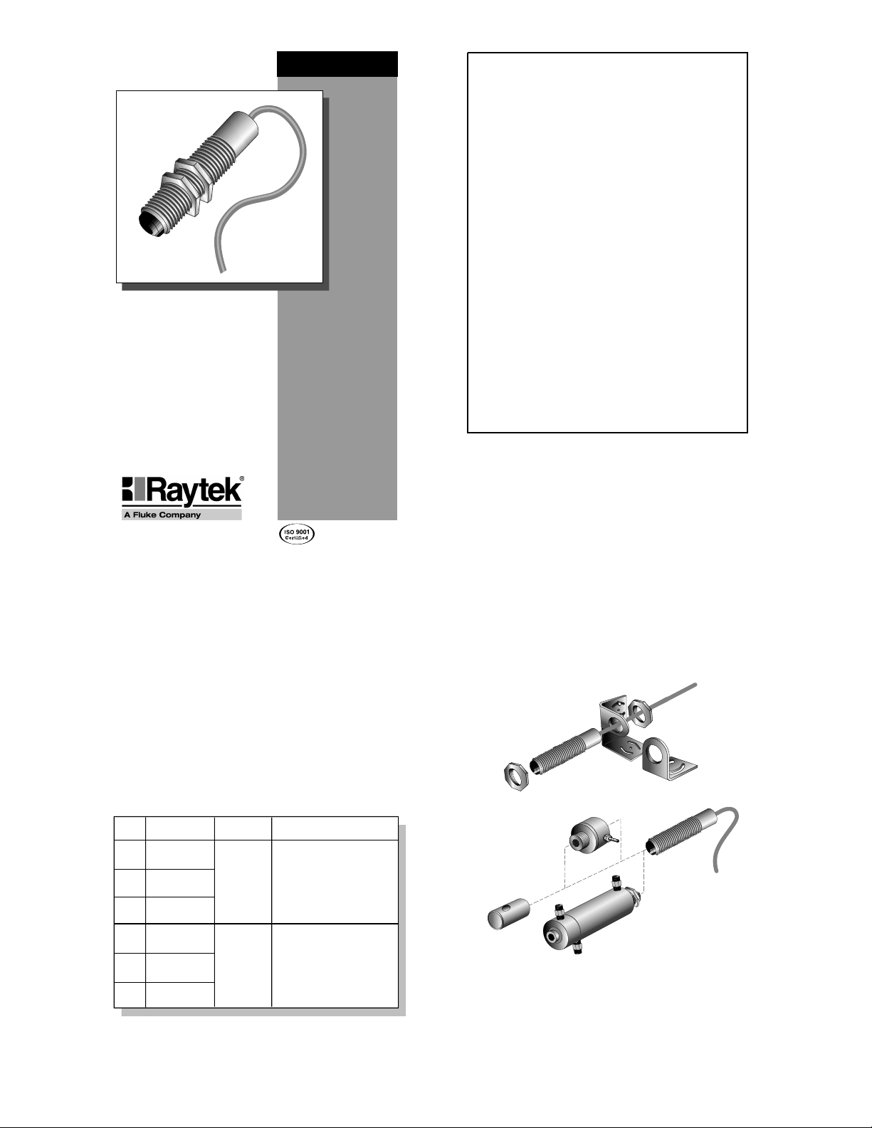
A full r ange of accessor ies for v ar ious applications and
industrial environm ents are av ailable ( see F igure 1).
A ccessories may be ordered at any time and added
on-si te. A lso avail able is a J- or K -type thermocouple
connection k it and extensi on cables.
T H ER M AL ER T C I
The T hermalert®C I™C ompact Infr ared Sensor series
of onli ne instruments are noncontact infr ared temperature measur ement sy stems. T hey are d esigned to measure accurately and repeatably the am ount of heat energy emi tted from an object and to conv ert that energy
into a measu rable electrical signal.
E ach mod el (see Table 1) comes with a 1 m (3 ft) cable
and tw o mounting nuts and is designed for easy integrati on into standard 4-wir e sy stems. T here are J or K
thermocouple output models or 10 mV / °C vol tage output mod els if your appli cation i s suscepti ble to noise or
requi res a long cable run. T he electronics are protected
by a r ugged N E M A 4 stainless steel housing.
2
1
A CC ES S OR I ES
Table 1: M odels
Fi gure 1: A ccessories and O ptions
THERMALERT SERIES
Mod el Ou tput Ac cu rac y
J The rmocouple
C I1A
K The rmocouple
C I2A
Vo ltage
C I3A
J The rmocouple
C I1B
K The rmocouple
C I2B
Vo ltage
C I3B
Ov era ll
Te mp. R ang e
0 to 350û C
(32 to 662 û F )
30 to 500û C
(86 to 932 ûF )
0 to 115 û C (3 2 to 24 0û F )
la rger of ±2% or ±3û C (±6 û F )
116 to 225 û C (2 41 to 4 40û F)
large r of ± 5% or ± 6û C (±1 0û F )
226 to 350 û C (4 41 to 6 62û F)
>±5%
100 to 5 00û C (21 2 to 932 û F )
la rger of ±2% or ±3û C (±6 û F )
30 to 99û C (8 6 to 21 1û F)
large r of ± 5% or ± 6û C (±1 0û F )
Adjus table mounting
brack et ac ces sory
F ixed
Mounting nuts
(2 supplied)
S ens or
Air purge colla r
ac ces sory
R ight angle mirror
ac ces sory
Air/Wa ter-cooled housing
mounting brac ket
ac ces sory
S ens or
with integrated a ir purge
(fac tory insta lled option)
Find Quality Products Online at: sales@GlobalTestSupply.com
www.GlobalTestSupply.com
Page 2

OPTIONS
Options for various applications and environments
are available. Options are factory installed and must
be ordered with base model units. These include the
following:
• NIST traceable certification
• Air/Water-cooled housing (comes with integrated
air purging and high temperature cable)
• High temperature cable–260°C (500°F) maximum
ambient temperature (comes standard with
air/water-cooled housing option)
• Longer 3 m (10 ft) standard cable
3
SPECIFICATIONS
Table 2 (below and continued on Page 4) lists the sensor’s optical, thermal, operational, electrical, environmental, and physical specifications.
Continued on next page
Table 2: Specifications
4
Table 2 (continued): Specifications
65
Optical Chart
Figure 2 shows you how to read the optical chart. The
optical chart (Figure 3) indicates the nominal target
spot diameter at any given distance from the sensing
head and assumes 90% energy.
Figure 2: How to Read the Optical Chart
INSTALLATION
The installation process consists of the following:
• Preparation
• Mechanical Installation
• Electrical Installation
The most important part of the installation process is
preparation. Please read the following section thoroughly before proceeding with the mechanical and
electrical installations.
Preparation
Distance and Spot Size—The size of the area (spot
size) you wish to measure determines the distance
between the sensor and the target (see Figure 3 for distances and spot sizes). The spot size must not be larger than the target. Mount the sensor so the measured
spot is the same or smaller than the target. Figure 4 is
an overview of proper sensor placement.
Figure 4: Proper Sensor Placement
Figure 3: Optical Chart
Optical Resolution
Spectral Response Range
Thermal
Measurement range
Detecting element
Accuracy
Repeatability
Temperature coefficient
Operational
Temperature resolution
Emissivity
Response time
Warm-up period
4:1
90% energy
@
7–18 µm
See Table 1
Thermopile
See Table 1
±1% of reading
0.2˚ C per ˚C (0.2˚ F per ˚F)
< 0.5˚ C (1˚ F)
Fixed at 0.95
350 mSec (95% response)
< 1 minute
Electrical
Power supply voltage
Maximum current draw
Ripple
Output impedance
Minimum load impedance
Outputs
Environmental
Sensing head rating
EMI
Conducted noise immunity
Relative humidity
Storage temp. range
Thermal shock
Ambient operating range
air cooling
water cooling
water cooling/high temp cable
Physical
Dimensions
Weight
Material
Cable–Standard
Maximum ambient temperature
Material (type & color)
Cable length
Gauge
Cable–High Temperature
Maximum ambient temperature
Material (type & color)
Cable length
Gauge
12 – 24 VDC @20 mA
≤ 10 mA
≤ 2.5%
50 ohms
50K ohms
J or K thermocouple,
10mV/˚C Linear Voltage
IP 65, NEMA 4
IEC 801-4, Level 1
10 to 95%, non-condensing
-30 to 85˚ C (-22 to 185˚ F)
Max error of 5˚ C (for ∆T=25˚)
stabilization time=20 mins.
0 to 70˚ C (32 to 160˚ F)
0 to 94˚ C (32 to 200˚ F)
0 to 105˚ C (32 to 220˚ F)
0 to 260˚ C (32 to 500˚ F)
19 mm dia x 87 mm L
(0.75 in dia x 3.4 in L)
130 g (4.5 oz)
Stainless steel
105˚ C (220˚ F)
PVC, grey
1 m (3 ft)
AWG 24 (J, K t/c cable)
AWG 22 (10mV/˚C cable)
260˚ C (500˚ F)
Teflon, black
1 m (3 ft)
AWG 24
Target spot size
at focus point
Diameter of target
spot size in millimeters
Focus Point D:S = Distance to spot divided by spot diameter at the focus point
Far Field D:S = Ratio at distances greater than 10x the focus distance
Diameter of target
spot size in inches
Distance from sensor to
object in millimeters or meters
Distance from sensor
to object in inches or feet
GoodBest Incorrect
Sensor
Target greater
than spot size
Target equal
to spot size
Background
Target smaller
than spot size
Find Quality Products Online at: sales@GlobalTestSupply.com
www.GlobalTestSupply.com
Page 3
Ambient Temperature—The sensing head is designed
to operate in ambient temperatures from 0 to 70°C (32
to 160°F). For ambient temperatures above 70°C
(160°F), a factory installed air/water-cooled housing
option is available that allows operation in ambient
conditions up to 260°C (500°F) with water cooling.
The air/water-cooled housing option comes with a
high-temperature cable and integrated air purging.
Atmospheric Quality—Smoke, fumes, dust, and other
contaminants can coat the lens and cause erroneous
temperature readings. We recommend using the air
purge collar accessory in these types of environments
to keep the lens clean. (The air/water-cooled housing
comes with integrated air purging.)
Electrical Interference—To minimize electrical or electromagnetic interference or “noise,” mount the sensor
away from motors producing large step load changes.
Wiring—Before installing, be sure to check the distance between the sensor and the monitoring/controlling device. If necessary, extension cables are available
as accessories.
Power—Have available a 12–24 VDC, 10 mA, power
supply.
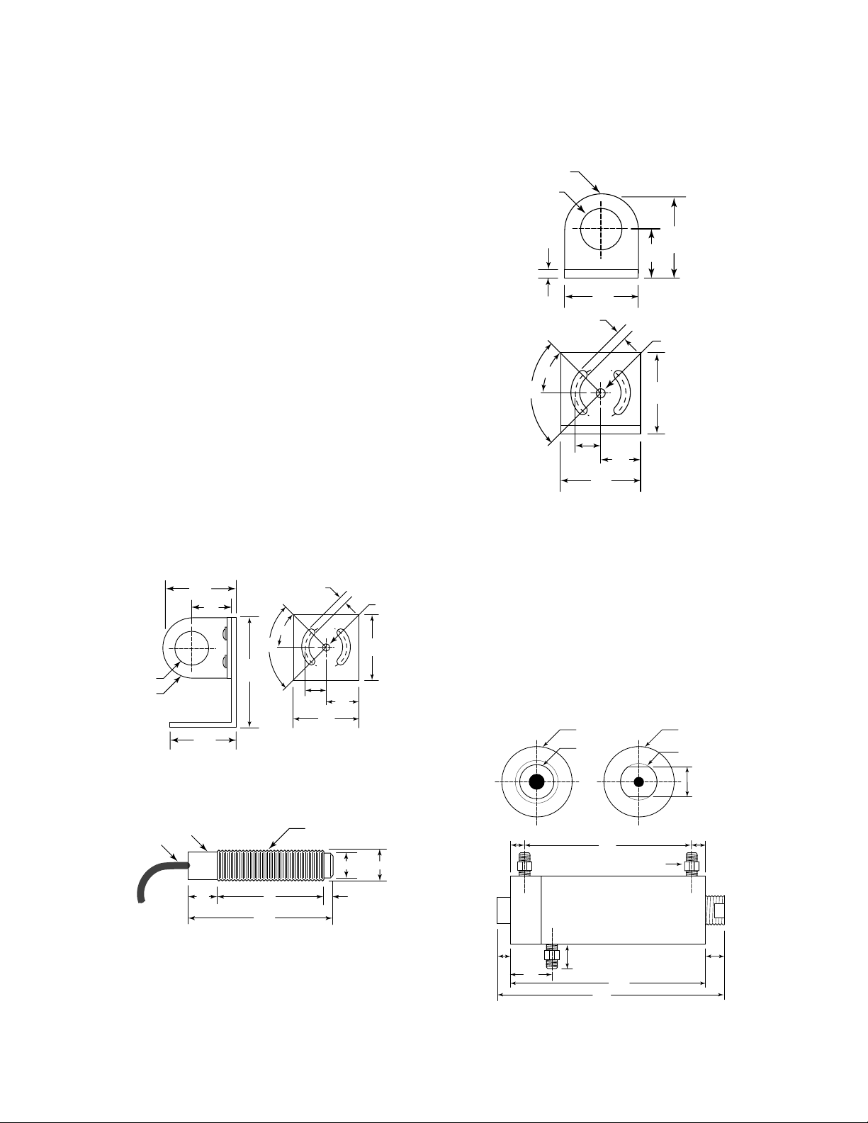
Mechanical Installation
All sensors come with a 1 m (3 ft) cable and 2 mounting nuts. You can mount the sensor in brackets or
cutouts of your own design, or you can use the fixed
and adjustable mounting bracket accessories. Figures
5 through 7 show the mounting bracket accessories’
and sensor’s dimensions.
8
7
Figure 5: Fixed Mounting Bracket
Air/Water-cooled Housing with integrated air purge—
The air/water-cooled housing option (Figure 8) allows
the sensor to withstand ambient temperatures up to
260° C (500° F) with water cooling and the high-temperature cable. (The high-temp cable is standard when the
housing is ordered as an option.) It has 1/8” NPT fittings for water and air. Water temperature should be
15-30° C (60-86° F) for best performance. Chilled water
below 10° C (50° F) is not recommended. Without the
high-temperature cable, the sensor can withstand ambient
temperatures only up to 105° C (220° F) with water cooling.
9 10
Figure 8: Air/Water-cooled Housing
Figure 6: Adjustable Mounting Bracket
Figure 7: Sensor
Full R
∅19 (.76)
38
(1.5)
(.75)
22
(.875)
∅5 (.196)
38
(1.5)
19
mm (inches)
2X 90˚
1.5
(.06)
2X 45˚
(.196)
2X 13
(2X .5)
38
(1.5)
5
38
(1.5)
∅19 (.76)
Full R
41
(1.625)
(1.5)
38
(.875)
22
2X 90˚
59
(2.31)
2X 45˚
(.196)
2X 13
(2X .5)
5
1 m (3 ft)
PVC Cable
∅4 (.17)
∅17 (.67)
(.75)
19
(3.5)
(2.48)
89
63
3/4"–16UNF 2A
M18 x 1 (if ordered metric)
19
(.75)
38
(1.5)
mm (inches)
∅14 (.56) ∅19 (.75)
(.27)
mm (inches)
∅5 (.196)
(1.5)
38
∅38 (1.5)
∅20 (0.8)
~ 25
(~ 1)
Rear View
96
(3.79)
1/8" NPT fittings (3)
118
(4.63)
137
(5.38)
Front View
10
(0.39)
7
6
(0.25)
25
(1)
∅38 (1.5)
3/4"–16UNF 2A
13
flats
(0.5)
(0.45)
~ 13
(~ 0.5)
mm (inches)
12
Find Quality Products Online at: sales@GlobalTestSupply.com
www.GlobalTestSupply.com
Page 4

11
Air Purge Collar—The air purge collar accessory
(Figure 9) is used to keep dust, moisture, and other
contaminants away from the lens. It must be screwed
in fully. Air flows into the 10/32” fitting and out the
front aperture. Clean or “instrument” air is recommended. The air purge collar accessory is not needed with
the air/water-cooled housing.
Figure 9: Air Purge Collar
Table 3: Recommended Water and Air
12
Right Angle Mirror—The right angle mirror accessory
(Figure 10) allows a perpendicular view of a target. It
may be used when space is limited or when you need
to avoid excessive radiation to the sensor. This can be
mounted either on the end of the sensor or on the air
purge collar, but not on the air/water-cooled housing.
Note: When using the right angle mirror, a small
amount of energy emitted by the source is lost, which
results in a lower than actual temperature reading. To
compute the corrected temperature, use this formula:
T = 1.035T
m – .035Tamb
where T=corrected temperature, Tm=temperature reading with mirror, and Tamb=ambient temperature. All
temperatures are in either °C or °F.
Figure 10: Right Angle Mirror
13
WARNING
Incorrect wiring will cause severe, per-
manent damage to the sensor.
Pay close attention to the wiring diagram in
Figure 11, and match your sensor to the appropriate output type in Table 4 or 5. Wire accordingly.
DO NOT CONFUSE OUTPUT WIRES WITH
POWER SUPPLY WIRES.
Electrical Installation
Sensor to Electronics Cable—The sensor to electron-
ics cable is a 1m (3 ft), 4-wire, PVC cable. One end is
attached, at the factory, to the sensor head. The
other end has two pairs of wires and a bare shield
(ground) wire (see Figure 11).
The unlabeled pair of wires is for connecting to a
controller or chart recorder or for attaching to a thermocouple plug (for connecting to a thermocouple
meter). DO NOT CONNECT TO APOWER
SOURCE.
The second pair of wires, with the label, is for connecting to a power source.
14
Figure 11: Wiring Configuration
Table 4: Standard Cable Wiring
Wiring—Wire the electronics cable using Figure 11 and
Table 4 or 5 (for high temp cables) as a guide. USE
ONLY THE OUTPUT TYPE OF YOUR SENSOR.
WIRING TO THE WRONG OUTPUT WILL DAMAGE THE SENSOR. Note in Figure 11 that the num-
bers refer to the wire numbers in Table 4 or 5, which
shows proper wiring connections based on insulation
color coding.
Inside threads M18 x 1
(if ordered with metric threaded sensor)
3/4" – 16UNF 2A
35
(1.36)
(0.42)
11
(0.84)
9
(0.37)
21
31
(1.21)
mm (inches)
∅19 (0.75)
10/32" threads
∅35
(1.38)
~ 25
(~ 1)
(2.38)
61
Recommended
Cooling water supply
Temperature
Flow rate
Pressure drop
Cooling air supply
Temperature
Flow rate
Pressure drop
Air purge air supply
Temperature
Flow rate
Pressure drop
(across unit only)
(across unit only)
(across unit only)
15–30˚ C (60–86˚ F)
1.89 liters per min (0.5 gpm)
< 0.69 bar (10 psi)
< 30˚ C (< 86˚ F)
70.8 liters per minute (2.5 SCFM)
< 0.34 bar (5 psi)
< 30˚ C (< 86˚ F)
11.33 liters per minute (0.4 SCFM)
< 0.34 bar (5 psi)
∅20 (.8)
3/4"–16 UNF 2B
82
13
(.5)
20
(.8)
31
(1.25)
mm (inches)
NOTE LABEL
(ON POWER
SUPPLY WIRES ONLY)
Wire Numbers
(Refer to Table 4 or 5)
12 – 24 VDC Red (+)
1
2
3
4
5 (Shield)
J-type
Thermocouple
K-type
Thermocouple
10mV/˚C
Voltage
Output
Power
Supply
–
Output
Power
Supply
–
Output
Power
Supply
–
Wire
Number
1
2
3
4
5
1
2
3
4
5
1
2
3
4
5
White
Red (white stripe)
Red (yellow stripe)
Yellow
Bare
Yellow
Red (yellow stripe)
Red (white stripe)
White
Bare
White
Green
Red
Black
Bare
FunctionWire ColorOutput Label
Signal + (Iron)
Signal – (Constantan)
Power Supply +
Power Supply –
Shield Ground
Signal + (Chromel)
Signal – (Alumel)
Power Supply +
Power Supply –
Shield Ground
Signal +
Signal Ground
Power Supply +
Power Supply –
Shield Ground
Find Quality Products Online at: sales@GlobalTestSupply.com
www.GlobalTestSupply.com
Page 5

E xten sion C ables—E xtension cables are avail able as
accessories. A lso av ailable is a thermocouple connection kit.
M A I N T EN A N CE A N D
T R O UB L ES H O O T I N G
If your sensor i s not perf ormi ng as it shou ld, tr y to
match the symptom in Table 6 to its probable cause. I f
the table does not help, call us at one of the phone
num bers listed on the last page.
Our custom er service representatives ar e al w ays at
your d isposal for appli cation assi stance, cali bration,
repai r, and solutions to specific questi ons or problems.
C ontact our Service D epartment before returning any
equipment to us. In many cases, problems can be
solv ed ov er the telephone.
I M PO RT AN T
Be aware of the foll ow ing when using the sensor:
If the sensor is exposed to significant changes in
ambient temperature (hot to cold or col d to hot),
all ow 20 mi nu tes f or the temperature to stabili ze
before tak ing or recording measurements.
Do not operate the sensor near large electri cal or
magnetic fields (e.g., around ar c w elders or i nduction heaters). E lectro-M agnetic I nterference (E MI)
can cause measurement errors.
C onnectors or w ires must be connected only to the
appr opr iate i nput jacks or terminals.
16
15
O PE R AT I ON
Once the sensor is in position and you hav e m ade sure
that the appropriate pow er, air, w ater, and cable connections ar e secure, the system is r eady for continuous
operation.
To operate, complete the fol lowing si mple steps:
1. Turn on the power supply.
2. Turn on the m eter, chart recorder, or controller.
3. R ead/ monitor the temperature.
WA R N IN G
I f usi ng the ai r /water-cool ed hous i ng, do not
leave i t in a heated envi ronm ent w i th the
coolant turned of f . D amage to th e s ensor and to
the hou sing can occur.
Table 5: H igh Temperature C able W ir ing
17
S ymp tom
No output
E rroneous Temp.
E rroneous Temp.
E rroneous Temp.
P ro ba ble C aus e
No power to se nsor
Incorre ct wire
conne ction
Fa ulty s ensor cable
F ield of view
obstruc tion
S olu tion
C heck the power
supply
C heck wire c olor
codes and reconne ct
Verify cable continuity
R emove obstruction
L ens C leani ng—K eep the lens clean at al l times. Blow
off loose par ticles (if not using the air purge accessory)
with clean com pressed air, then carefu lly wi pe sur face
with moist cotten swab (w ater or w ater-based glass
cleaner ). D O N O T use sol vents.
Table 6: Troubleshooting
Wi re
Nu mber
J -type
The rmocouple
K -type
The rmocouple
10mV /ûC
Volta ge
Output
P ower
S upply
Output
P ower
S upply
Output
P ower
S upply
1
White
2
R ed ( white s tripe)
3
R ed
4
Y ellow
5
Ð
Ð
Ð
B are
1
Y ellow
2
R ed
3
R ed ( white s tripe)
4
White
5
B are
1
R ed
2
Y ellow
3
R ed ( white s tripe)
4
White
5
B are
F unc tionWi re C olo rOu tput L abe l
S ignal + (Iron)
S ignal Ð ( Cons tantan)
P ower S upply +
P ower S upply Ð
S hield G round
S ignal + (C hromel)
S ignal Ð ( Alumel)
P ower S upply +
P ower S upply Ð
S hield G round
S ignal +
S ignal G round
P ower S upply +
P ower S upply Ð
S hield G round
Find Quality Products Online at: sales@GlobalTestSupply.com
www.GlobalTestSupply.com
 Loading...