

Page 1
How to use this Manual
To get
the full functionality of this manual we
recommend to use Adobe®Acrobat
Reader®5 or higher.
It is availabe at:
http://www.adobe.com
Once you have open this manual in
Acrobat Reader choose the tab “Bookmark” at the left to see the Table of
Contents.
These headlines are linked with the
corresponding chapters of the manual.
Just click on a headline to see the
chapter in the main window.
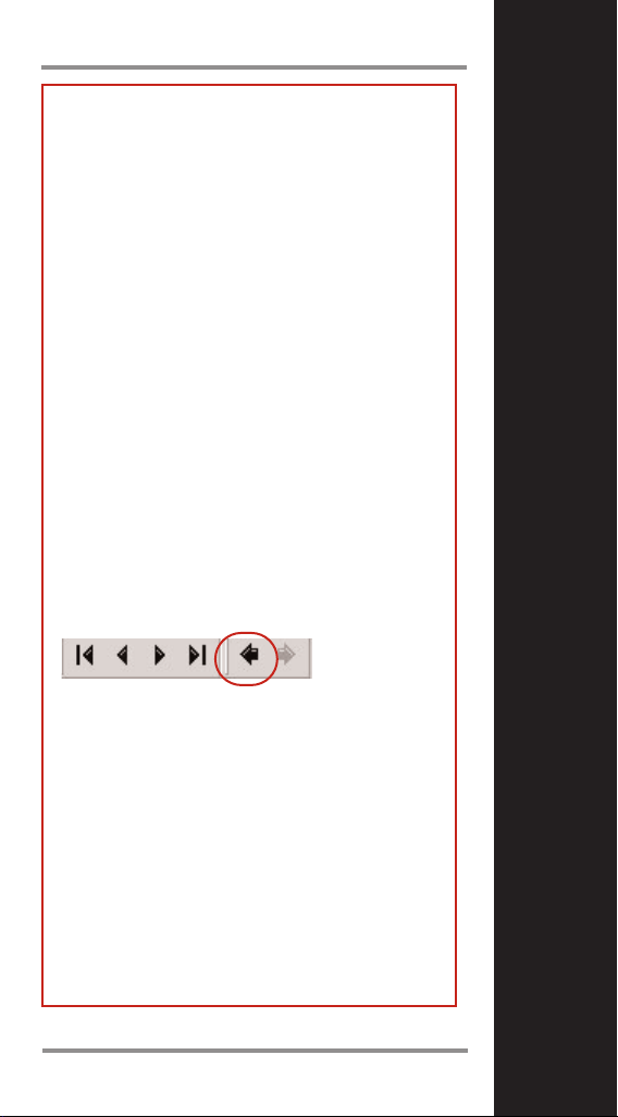
Sometimes you’ll find phrases in the
text marked red. These will guide you
to additional information. To go back to
the manual use this arrow button in the
upper bar of Acrobat Reader.
1
Page 2

3
2
Basic Mode
This chapter is dedicated
to explore the unit and the
software and to get familar with its basic functions.
It helps to get first results
fast and easy.
It explains the software
installation and how to use
the unit with factory defaults.
Please take a bit time and
follow up carefully.
Once you feel trained
enough go to the
“Expert Mode” to find out
what else this unit can do for
you.
Page 3

5
Before Starting
4
Requirements
To use the unit and the software you need a
Windows compatible PC with a minimal configuration:
• 200 Mhz processor (400 Mhz recommended)
• CD/DVD drive
• USB 1.1 - port
• 15 MByte free diskspace on the hard drive
The software works with
Windows
®
98, ME, XP and 2000.
Note! With a fresh set of batteries, the unit can
store photographs for up to 2,000 hours.
However, we recommend that you download
photographs soon after you have taken them.
To avoid the loss of photos you should change
the batteries within two minutes after the unit
has shut down completly.
Page 4
6
7
Signs and Icons in the Manual
Introduction
We hope that you enjoy using your photographic
infrared thermometer!
It measures the amount of infrared energy emitted by a target object, and calculates the
temperature of that object´s surface. In addition,
it takes a photo of the measured spot highlighted by a bright laser circle. In a few easy steps
you can create reports that incorporate the
photo of the target and also the temperature,
location, date/time, and a description - all this
can be customized by using the software
delivered with the unit.
Your unit includes:
-A digital camera synchronized with the
temperature measurement
-True Spot laser Sighting
- Nameable locations
- Adjustable emissivity
- High/Low alarm
- Data logger
- ...and a lot more!
Features
Delivery Content
If you see this icon, use the unit to follow the
steps described.
If you see this icon, you should have started
your PC and the companion Software delivered
with your unit.
If you see this icon, the unit is connected
to the PC.
Software descriptions appear in a grey textbox
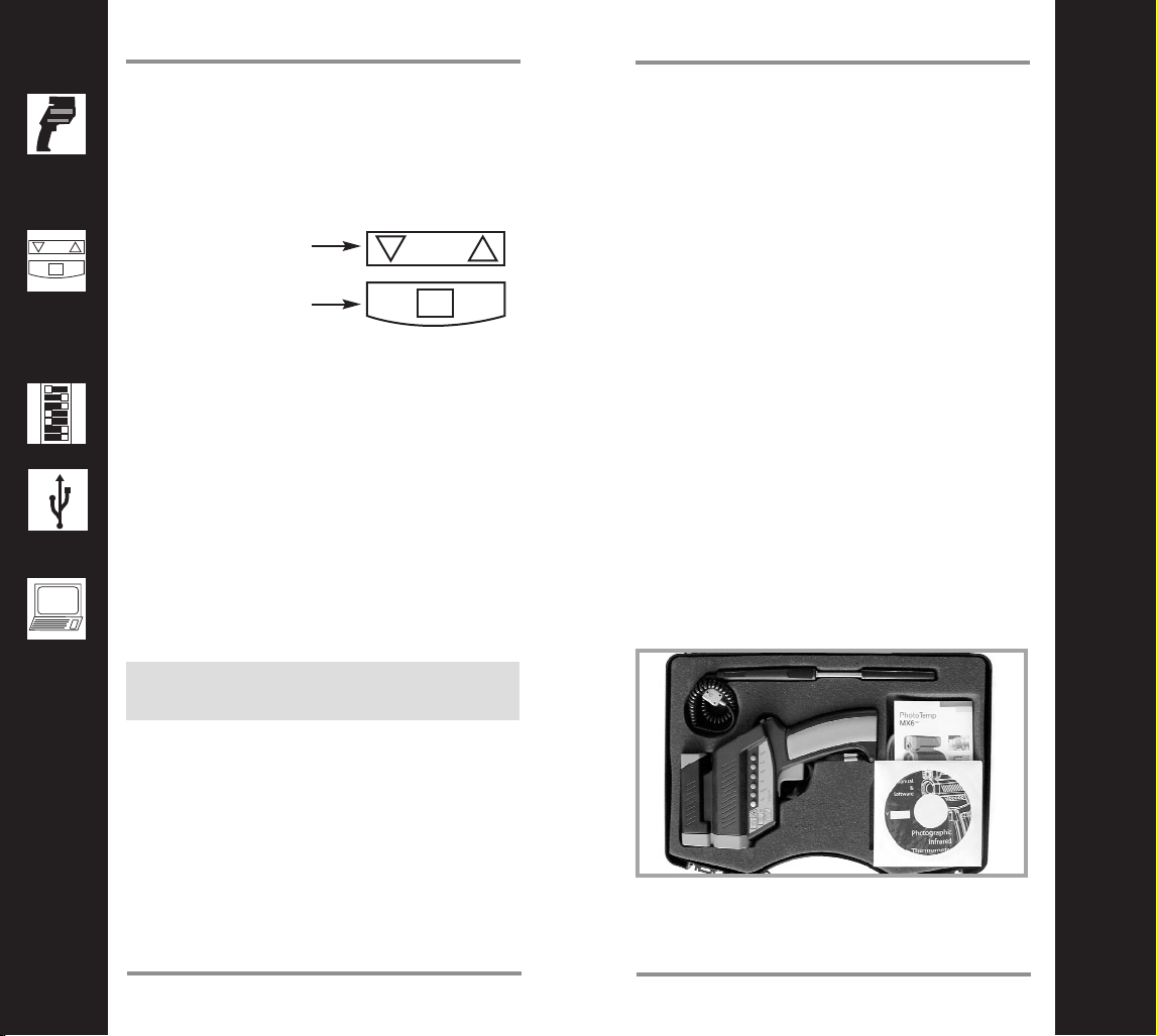
This icon shows that
you can adjust values
with these buttons on
the unit.
To store these values
press the ENTER button on the unit.
This icon shows that there are additional options
related to the DIP-switch settings.
The unit • Thermocouple Type K probe • Windows-based software on CD • USB cable • Two
AA batteries • Manual on CD • Quick start
Page 5
8
9
Configuration of the PC
Installing the software
Hardware Setup
Connect the unit to the PC via USB.
New hardware will be found. You have to
install three different device drivers - two
for USB ports and one for the USB camera.
A device driver is software needed by your
PC to communicate with the unit. You will
be asked three times to install a driver.
Note! During driver installation, a message
window could appear, indicating that a particular driver is not supported or authorized by
Microsoft. Please ignore this message and continue with the installation.
The Windows Hardware Assistant will guide
you through the installation process. If you are
asked where to look for the drivers, choose
CD-ROM.
In most cases Windows will find the drivers
automatically. It could happen, that Windows
asks for the file STV680u.dll. This file is located
in the drivers folder on the CD.
Software Setup
1. Insert the CD into your CD drive.
2. Double click on setup.exe.
3. Follow the instructions, shown on the
screen.
4. Launch the software.
The software is now ready to use.
Plese read the following information first and
configure language, time, and date if
necessary.
This configuration can be repeated at any time.
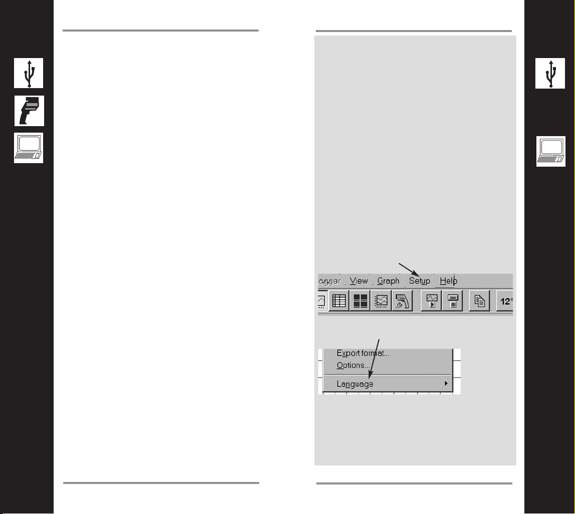
Software Language
To choose one of the available languages of the
software, go to “Setup”.
Click on “Language” in the Pull Down menu.
Then make your selection.
Page 6
11
Configure Date and Time
10
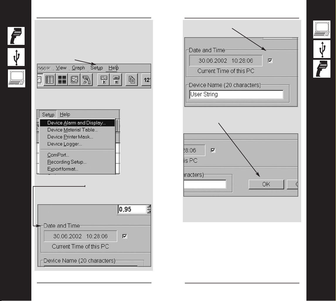
Configure Date and Time
Set Date and Time of the unit
To get the right date and time stamp in your
picture, proceed with the following steps:
1. Choose “Setup” in the software’s menu bar.
2. Go to “Device Alarm and Display”
3. Look for “Date and Time” and verify that the
correct values are shown (these values
depend on your computer system settings)
4. Enable the checkbox to the right of the values.
5. Click on “OK”.
6. Disconnect the unit from the PC.
Page 7
13
Basic Mode
12
Simply turn the lens focus ring depending on
the distance of your target.
How to focus the camera
Between
0.2 m
(8 in) and
0.3 m
(12 in.)
adjust the
lens to the
flower
symbol.
Between
0.5 m (19 in)
and infinity
adjust the
lens to the
mountain
symbol.
This is a simple aid to understanding the
camera’s field of view. The opening angle of the
lens is approximately 40°.
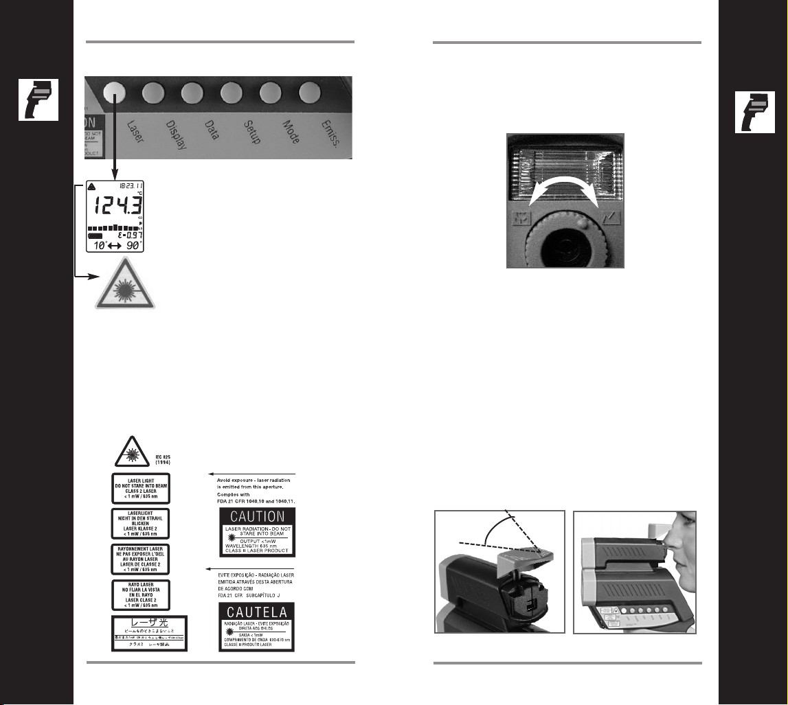
Rotate the cap up to a horizontal position and
look over it, as shown below. The embossed
triangle will show you the approximate width of
the photo.
The view finder guide
Laser ON and OFF
laser ON
symbol
The laser circle shows the
spot size that includes the
measured target. To turn
the laser On or Off, press
the LASER button when
the trigger is pulled.
A laser symbol appears
when the laser is on. The
laser automatically turns
off if you release
the trigger.
CAUTION!
Do not stare into beam!
Avoid indirect exposure via reflective materials!
Laser Warning Label
Basic Mode
40°
Between 0.25 m
(10 in.) and 0.6 m
(23 in.) adjust the
lens in the middle of
both symbols
Page 8
15
Basic Mode
14
Basic Mode
1. To switch on the unit, pull the trigger.
2. Press the “Enter” button to activate the
camera while the display is active.
3. First the word “LOG” flashes and then the
camera icon appears.
The unit is ready to use now! It is preset to
take 26 pictures!
4. Pull the trigger and hold it. The laser circle
shows where you are measuring.
5. Aim at the target. Be sure that the laser
circle is inside the target.
6. Gently release the trigger to record the
photo and the temperature. Successful
recording of picture and temperature is indicated by two short beeps and a green
shining LED above the display. The next
location will be shown on the display.
Caution:
If you hear a longer beep and the LED
above the display is shining red, look at the
display. If you see “Use Flash!” and a flash
symbol, repeat your last measurement. A
small green LED above the camera icon
signals: “Flash has charged”. The flash will
now fire automatically.
7. For the next measurement repeat points
5 and 6.
8. Once you have taken all your photos,
connect the unit to the PC via USB.
9. Start the software on your PC. After a few
seconds, the data download begins. Click on
“OK” if a message about logger file and unit
configuration incompatibility appears. Click
on “Yes” if you are asked to download all
images
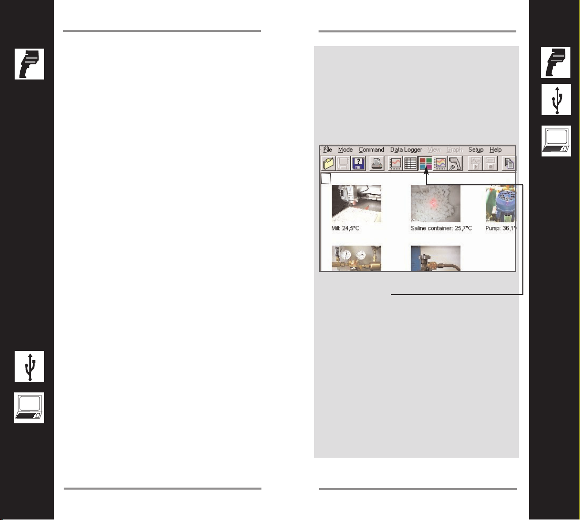
10. See your pictures and data as a thumbnail
collection.
11. If this doesn’t happen automatically, toggle
to this button.
Page 9
16
17
Basic Mode
Basic Mode
Once you have downloaded all data from the
unit to the PC, save the data as library.lgg file.
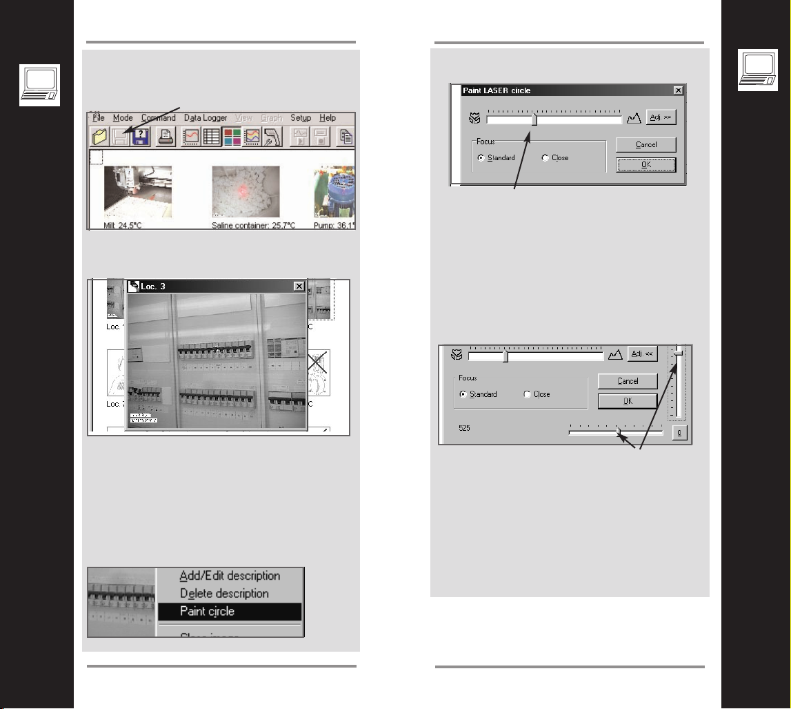
To edit a picture, click on it once with the left
mouse button. It will be enlarged.
Now you are able to add discriptions to the
photo or to insert a drawing of the laser circle.
This may be necessary, if the ambient light was
too bright while taking the photo and the laser
circle is hard to see.
Right clicking on the photo will open a menu,
where you can choose what you want to do.
Additional software features
If you choose “Paint circle” the following window
appears.
With the distance slider you could adjust the
size of the laser circle drawing corresponding to
the original size of the real laser circle.
NOTE: This feature will only work properly, if
you have adjusted once the circle drawing
to the camera with the following procedure:
Ta ke a photo - enlarge it in the software - draw
a laser circle - adjust the size with the distance
slider as shown above - adjust the place of the
circle by using “Adj.” and then these sliders.
The drawing will be stored within the photo. The
same happens with the description function.
With the “Copy image” function you can create
a report easily by pasting the photo into a programme of your choice.
“Print Image” starts the printers dialog of your
standard printer. Now you can print out a single
photo.
Page 10

19
18
Expert Mode
Expert Mode
This chapter is dedicated
to the advanced user and
based on the
“Basic Mode” part of this
manual.
We recommend to going
through this part step by
step to get the most benefit
out of the unit.
For additional information
contact the manufacturer or
refer to its website.
(See back page of the cover
of the printed manual.)
In the “Basic Mode” chapter you have seen how
easy it is to use this unit and to store photos
and data.
A special file has been created automatically by
the unit, based on the factory defaults. This file
is called “Logger” and has the extension “lgg”.
Under special circumstances it may happen,
that the factory default settings don’t match your
needs. In that case, it is possible to customize
the factory default logger file.
You may wish, for instance, to name the locations where you want to measure or to add different emissivity values or special materials.
Additionally it may necessary to add more than
just temperature, location, date and time information to the photos.
All this is possible and explained in the next
few pages
Page 11

21
Expert Mode
20
Expert Mode
How to create a logger file?
Note! The following operation will
change the current settings in the
unit!
Configure an inspection table using the menu
SETUP/DEVICE LOGGER. The following screen
display will appear.
Continue by setting the desired number of the
inspection points to be measured in the table at
the lower right. In our example it is 5. Choose
the desired image resolution. “High” means a
resolution of 640x480 pixels, “Low” is
320x240 pixels.
Please note! In both modes you could configuere up tp 100 positions. If you have chosen
“High” the maximum number of photos is 26.
In the “Low” resolution mode, you can take
more than 100 photos. The camera memorycan store up to 106 photos. This could be helpful, if you want to repeat a photo at a previous
position.
Next, enter the name of the location and insert
the related material from the material table by
clicking here. For a known emissivity enter the
value in the column EMS. In the column “Image”
you could enable or disable taking a photo by
checking the appropriate box
The material names are stored in a material
table file. This can be customized. See chapter
“How to create a material table?”
Save this logger file with a new name by
clicking on the “Save as” button. With a click on
“OK” transfer the table to the unit.
Now go to the Logger view by clicking here and
open the file you have just saved
Page 12

23
Expert Mode
22
Expert Mode
Examples
Disconnect the unit from the PC and begin your
inspection.
Once the inspection has been done, transfer
data and photos to the PC. Connect the unit via
USB to the computer, while the software is running. The data transfer begins automatically
when the message “Connected” appears.
Now you can set up which data fields should be
inserted in the photos after you have taken
them. All columns you choose here will be included in the final photo.You can’t delete any information from the photo itself. To open the sub-
menu simply right click into the table
With the following dialog choose and order the
columns.
Note! The more data you insert in the photo the
more these data will hide the picture. Especially
if your working in the low resolution mode, we
recommend to choose only a few columns.
See the examples!
Many columns
chosen
Fewer columns
chosen
Page 13

Ta ke your photos and data as described above
and save them by pressing disc buttoninto the
same file as before.
The number of inspections is shown in the bot-
tom line of the window
To see changes of the temperature over time,
you can create a routing graph.
This feature is very useful to monitor measurement points over time and identify problematic
trends.
For instance, in electrical panels, it is difficult to
find out that something is outside the normal
temperature range, especially if the panel has
live voltage. If you monitor the panel over time,
you find out, where the problems are, before
they become dangerous.
Go to
and then open the logger file you have just
created.
25
Expert Mode
24
Expert Mode
The photos and data appear in a thumbnail preview. To see the table click here.
With a right click into the table you open a sub
menu.
By choosing “Columns” you can add or delete
columns to show all the data you have saved.
Save the data. This will delete the unit’s
memory and the unit is now ready for the next
inspection.
Page 14

27
Expert mode
26
The result.will look as follows:
The routing graph
Expert Mode
The following dialog appears:
Now select in the curves menu up to five
objects measured and set up their appearance
in the graph.
Then choose the time frame of the measurement.
Page 15

29
28
Expert Mode
How to create or edit a material table?
This function enables you to easily create
customized material / emissivity tables that
meet your requirements.You can then transfer
the table, online, to your thermometer. Proceed
as follows:
Choose the item DEVICE MATERIAL TABLE
from the menu SETUP.
The following screen display appears.
Creating a New Material Table
The cursor is located in the first line under the
entry MATERIAL. Enter the name of the first
material here. In the same line enter the associated emissivity under EMS. To access the
other fields, use the keyboard or the mouse and
fill in the complete table. Now save the table by
clicking the button SAVE TO FILE. In the subsequent window (see next page) enter the file
name; the file suffix "mat" is automatically
appended.
Save the file in a directory on the drive of your
choice. We recommend the directory name
"Material."
Default Material Table
For your convenience we have provided a selection of 30 common materials. To access these,
simply click FACTORY DEFAULT with the primary mouse button or choose a material table
in the language you need by selecting
LOAD FROM FILE.
A complete table will appear as shown above.
By clicking OK you transfer this table to the unit.
Editing an Existing Material Table
Just as easily you can edit a material table. To
call up the table, choose the function LOAD
FROM FILE in the editing window.
By selecting and overwriting, you can modify the
list as you prefer and then save it again.
Page 16

31
Expert Mode
30
Expert Mode
Temperature Monitoring mode
Using the software, the unit can monitor
temperature and take photos automatically.
This happens when the temperature exceeds
the preset values for high or low alarm.
Proceed as follows:
Install the unit on a tripod.
Adjust the measurement direction with the help
of the live video window of the software.
Then go to “Setup” menu in the software and
choose “Device Alarm and Display...”
Choose the alarm values for which you want
the unit to take a photo when exceeded. If
necessary, choose the material of the target or
emissivity value.
Then click “OK”.
Now go to “Recording setup” in the setup
menu.Mark when the snapshot should be taken
- at high alarm or low alarm.
The “min. interval(s)” setting means that the unit
only checks after this interval for the alarm values exceeded.
A photo will only be taken if an alarm is newly
exceeded.
The snapshots will be taken in the measurement and recording mode.
But you can only save the data for later documentation in the recording mode.
The “Max. number of images” is limited only by
hard disk space. The file size of a low resolution
photo is approxomate 30 kB and for high resolution 60 kB.
The live video window appears in both modes.
Please do not close it. Otherwise the snapshot
mode will not work.
To resize the live video window, simple click the
right mouse button and choose another size.
When you press the recording or measuring
button again to stop the process, you will be
prompted for a file in which to save the
temperature data.
Page 17

33
32
Expert Mode
After taking the snapshot, you can see the
photos by clicking on the square markers in the
graph.
Page 18

34
35
Appendix A - Unit functions
Appendix A - Unit functions
Selecting a function
1. To switch on the unit pull and release
the trigger.
2. While the display is active, push the button
of the desired function.
3. Many of the functions are adjustable by
using the Up and Down keys.
For storing, press ENTER.
1
2
3
The DIP switches
Some functions of the unit be changed by using
the DIP switches. These switches are located in
the Battery compartement of the unit.
ON
Sets the unit into continuous measuring mode
Switches between
degrees Celsius and
Fahrenheit
Switches acoustic
signals On or Off
Switches the backlight of
the display On or Off
Sets the unit’s values to
default, if On
If On, the function
buttons are blocked
If On, the laser will flash
when temperature values exceed alarm
If On, photoflash is
activated
Auto = automatic flash use
All = every photo is taken
with flash
Time or Date will be
displayed
Thermocouple settings refer to the
corresponding
chapter
ON
Lock
°C/°F
Buzzer
Backlight
Set Default
Ltd. Access
Laserflash
Photoflash
Auto/All
Time/Date
NTC/TC
TC-J/TC-K
Page 19

37
Appendix A - Unit functions
36
Appendix A - Unit functions
The Data button
Press Data once to activate the log
mode of the thermometer and the
camera. With the right logger file
configuration, you can store
temperature values and photos.
The configuration of the logger file
is performed by the companion
software.
By pressing the Data button twice, one of the
following four displays appears.
“RCL” is displayed for the recall mode.
A photo and
a temperature value
have been
stored at this
Logger position.
Only a
temperature
value has
been stored
at this logger
position.
Camera is
active at this
logger position. Nothing
has been
stored.
Camera is
inactive at
this logger
position.
Nothing has
been stored.
The Display button
The last ten measurements are
shown in the bar graph on the
unit’s display. Auto Range of the
bar graph is automatically defined
by the measured maximum and
minimum value. Manual Range
(Man Range) is user defined.
CYCLE allows the adjustment of
the display interval of the bar
graph.
Press Display once to see how
many photos are already taken.
This sets up the BEGIN value for
the graphic display of the bar
graph. The graphic display shows
the temperature as a picture.
This sets up the END value for the
graphic display of the bar graph.
Page 20

39
Appendix A - Unit functions
38
Appendix A - Unit functions
The Setup button - HiAL, LoAL, Time...
High alarm (HiAl)
generates an audible and visual
(flashing LED and laser) alarm if
the temperature is above the
setpoint.
Low alarm (LoAl) generates an
audible and visual (flashing LED
and laser) alarm if the
temperature is below the setpoint.
This function is used with a selected
emissivity to add or subtract an offset
value (±10°C/±18°F) to the temperature
value.
The OFFSET feature allows the
temperature values for several units to be
matched, correcting for the allowed
temperature tolerance difference between
units. The OFFSET function can also be
used to increase the accuracy for a narrow
temperature range.
Change the time using the Up and Down
keys.Then press ENTER for each time
segment to activate this time setting. The
segment flashes whilst being set. The
time is stored within the data logger.
Change the date using the Up and Down
keys.Then press ENTER for each date segment to activate this date setting. The segment flashes while being set. The date is
stored within the data logger.
...Date, Offset, Clear Images
This feature deletes all
photos from the unit’s
memory.
“Clear Image Press
Enter” is shown as a run-
ning string in the bottom
line of the display
BE CAREFUL if you use
this function. The pictures
cannot be restored.
Back to the
Setup Button
The configuration of the alarm values can
also be performed by the companion
software.
Page 21

41
Appendix A - Unit functions
40
Appendix A - Unit functions
The Mode button - MINMAX, Material, MAX...
...MIN, DIF, AVG,
To activate the MAX mode, press
MODE until the MAX symbol
appears . The measured maximum
temperature is displayed as long
as the trigger is pulled or locked
on. The real time temperature is
shown in the lower part of the display (NORM).
To show which specific material
has been choosen for the specific
location, press MODE until the
name appears in the bottom line.
If “Free” appears, you can change
the emissivity settings by using
the Emiss. button, when not in
LOG mode. See chapter The
Emiss. button!
To show the minimum and maximum temperature values during a
measurement at the bottom of the
display, press MODE until the two
values appear.
To activate the MIN mode, press
MODE until the MIN symbol
appears. The measured minimum
temperature is displayed as long
as the trigger is pulled or locked
on.The real time temperature is
shown in the lower part of the display (NORM)
To activate the DIF mode, press
MODE until the DIF symbol
appears. The difference between
the measured max and min temperatures is displayed as long as
the trigger is pulled or locked on.
The real time temperature is
shown in the lower part of the display (NORM).
To activate the AVG mode, press
MODE until the AVG symbol
appears. The average value of
measured temperatures is diplayed
as long as the trigger is pulled or
locked on. The real time
temperature is shown in the lower
part of the display (NORM).
Next page
Page 22

43
Appendix A - Unit functions
42
Appendix A - Unit functions
s
ON
Open the battery compartment and set the switches
ON or Off according to the
desired probe type.
NTC - thermistor
TC - thermocouple
Thermocouple type J
Thermocouple type K
Connect the probe to the input.
The input is located at the bottom of the handle behind the
rubber cover.
Press MODE, until the desired
probe symbol (TC-K shown
here) appears. The probe
temperature is shown in the
lower part of the display. The
real time infrared temperature is
shown in the main display.
The Mode button - Thermocouple Settings
back to
Mode
button
The Emiss. button
To choose the emissivity of a material, press EMISS.
The display shows a material
name, an emissivity value, and the
calculated temperature value. To
choose another material, use the
Up and Down keys.
Press ENTER to activate this setting.
To adjust the emissivity value,
press EMISS., when not in LOG
mode. Use the Up and Down keys
to select “Free“ (“F
ree” will have a
flashing underline).
Press EMISS again. “Free” is not
underlined, and the emissivity icon
flashes. Use the Up and Down keys
to adjust. Press ENTER (D) to activate this setting.
ON
Lock
°C/°F
Buzzer
Backlight
Set Default
Ltd. Acces
Laserflash
Photoflash
Auto/All
Time/Date
NTC/TC
TC-J/TC-K
Page 23

45
Appendix B
44
Appendix B
To adjust the unit’s emissivity value for a
material with unknown emissivity, plug in the
probe.
Pull the unit’s trigger. Place the measuring
tip of the probe on the area to be measured.
Wait for the reading to stabilize.
Note the indicated probe temperature reading.
Release the trigger.
Pull the trigger again. Measure the same area
using infrared measurement.
Press the emissivity button. Use the Up and
Down keys to select the material name “Free”
which will be shown in the display. Press the
emissivity button again until the emissivity sign
flashes. Use the arrow keys to change the
emissivity value until the temperature matches
the probe’s reading.
The amount of infrared energy radiated by an
object depends on its emissivity and its
temperature.
The emissivity depends on the material and its
surface characteristics.
Note: For more accurate readings, adjust the
emissivity value for the type of material being
measured.
Emissivity explained
Unknown Emissivity Value
Reflected energy
Emitted energy
Tr ansmitted energy
Target
EMISSIVITY
Page 24

47
Appendix B
46
Appendix B
The measured spot size depends on the
distance between the object you are measuring
and the infrared thermometer.
The relationship between distance and spot size
is 60:1 at the focus point.
The D:S in the far field (>33ft/10m) is 35:1.
The measured spot size depends on the distance
between the object you are measuring and the
infrared thermometer. The relationship between distance and spot size is 50:1 at the focus point.
The D:S in the far field is 12:1.
The best distance between sensor and object is from
10 cm (4“) up to 50 cm (20“).
Optical Resolution (Infrared Themometer)
Standard Focus Model
Optical Resolution (Infrared Thermometer)
Close Focus Model
STANDARD MODEL
Optical Chart
DISTANCE: SENSOR TO OBJECT (IN)
0
30
20
36
46
48
0.76 IN @ 46 IN
SPOT DIA. (IN)
1.0
0.9
0.87
23
24
24
250
100
500
0
SPOT DIA. (mm)
DISTANCE: SENSOR TO OBJECT (mm)
FOCUS POINT D:S = 60:1 FAR FIELD D:S = 35:1
1.2
0.82
0.81
19.8
29.0
19 mm @ 1150 mm
1000
60
1500
1.51
84
72
1.85
44.0
2000
58.0
108
100
2.3
2500
120
2.9
2.5
72.0
3000
CLOSE FOCUS MODEL
Optical Chart
DISTANCE: SENSOR TO OBJECT (IN)
0
6
7.9
2
SPOT DIA. (IN)
1
0.9
0.75
18,7
22
25
0
50
SPOT DIA. (mm)
DISTANCE: SENSOR TO OBJECT (mm)
FOCUS POINT D:S = 50:1 FAR FIELD D:S = 12:1
9.8
4
0.24 IN @ 11.8 IN
0.62
0.49
0.37
9,2
12,3
15,5
6 mm @ 300 mm
150
100
200
250
20
0.93
Close Focus
23
500
40
2.81
70
1000
Page 25

49
Appendix B
48
Appendix B
Aluminum* 0.30
Asbestos 0.95
Asphalt 0.95
Basalt 0.70
Brass* 0.50
Brick 0.90
Carbon 0.85
Ceramic 0.95
Concrete 0.95
Copper* 0.95
Dirt 0.94
Frozen food 0.90
Hot food 0.93
Glass (plate) 0.85
Ice 0.98
Iron* 0.70
Lead* 0.50
Limestone 0.98
Oil 0.94
Paint 0.93
Paper 0.95
Plastic** 0.95
Rubber 0.95
Sand 0.90
Skin 0.98
Snow 0.90
Steel* 0.80
Te xtiles 0.94
Water 0.93
Wood*** 0.94
*oxidized
** opaque, over 20 mils
***natural
Table of emissivity values of common materials
The DIP-switches are located in the battery
compartment (8). In the beginning we recommend you use the default DIP-switch settings.
DIP switch settings - Factory Defaults
Factory Defaults
DIP-Switch Settings
ON
Lock
°C/°F
Buzzer
Backlight
Set Default
Ltd. Access
Laserflash
Photoflash
Auto/All
Time/Date
NTC/TC
TC-J/TC-K
Celsius setting shown
ON
Lock
°C/°F
Buzzer
Backlight
Set Default
Ltd. Access
Laserflash
Photoflash
Auto/All
Time/Date
NTC/TC
TC-J/TC-K
Fahrenheit setting shown
Page 26

51
Troubleshooting
50
Troubleshooting
Symptom
Display Code Problem Action
Camera cannot Driver installation Open
send photos failed Harware Manager on
to the PC the PC to fix it
-O- Target temperature is over Select target
-U- or under range within unit’s specs
EEPROM-Err EEPROM error Contact Factory
CalAreaErr calibration errors Contact Factory
ProbCalEr
Flash needs Battery is low Replace Batteries
too long to
charge or does not
charge at all
Blank display Battery is dead Replace Batteries
Laser won’t Low or dead battery Replace Batteries
work
Ambient above 45°C (113°F) Operate unit in
45°C (113°F)
ambient or below
Display “ON” Display locked “ON” Disconnect the unit
from the PC
Photos lost Batteries changed before Wait for shutdown
shutdown or too long to end. Change
after removing old ones batteries within two
minutes of removing
old ones
PC displays “logger The setup in the unit and Click “OK”. Either save
file does not match in the PC software do not the current data to a
device logger setup” match new file name or find
the correct *.lgg file,
open it in “Setup
Device Logger”, save,
and redownload the
data with the “Data
Logger/Load Device
Data Logger”
Sometimes a long beep and the red LED above
the display shines to indicate a problem, check
your display to find out which problem has
occured.
Symptom
Display Code Problem Action
Photo quality Light is sufficient for photo Use Photoflash
diminished with without flash always on (Dip switch
available light. “Auto/All”set to “All”
(Abrupt transitions or provide more
between color shades) ambient light.
Connection of unit Wrong com port selected Select correct com
to PC software or correct com port in use. or disconnect other
does not happen device from correct
when software started com port
No picture in More than one video Right mouse click
“Live” mode source is installed on the “Live” mode
window window. Choose
correct “Video source”
in the menu.
Unit indicates The light is too bright for Go to next location
“Use flash” in a photo or reduce brightness.
bright light
Unit leaves LOG The last position has been used If for the data and
after a photo and to record photo and data. photos required, then
data recorded. push Enter button and
use arrow keys to
re-record a position.
Photo Mem! All memory for storing photos 1. Download existing
has been used. photos and data and
clear memory.
- or -
2. If you don’t mind
losing photos
in the unit, you can go
to Setup in the unit,
push the button until
“Clear photo” appears
in the display and
press Enter.
Page 27

52
53
Maintenance
Lens Cleaning:
Blow off loose particles using clean
compressed air.
Brush remaining
debris away with a
camel’s hair brush.
Wipe the surface
with a moist cotton
swab. The swab
may be moistened
with water or a water based glass cleaner.
NOTE: DO NOT use solvents to clean the plastic lens.
Cleaning the Housing: To clean the
exterior housing,
use soap and water
or a mild commercial cleaner. Wipe
with a damp
sponge or soft rag.
Page 28

55
CE Confirmity
54
Important Hints
Avoid static electricity, arc welders, and induction
heaters. Keep away from very strong EMF
(electromagnetic fields).
WARNING: DO NOT touch live voltage with
contact probe.
Manufacturer,
Address
Made in Germany: Month, Year
Model: XXXXXXX
Serial: 000000-0000-0000
Power Requirements 3 V
SERIAL NUMBER LABEL
Avoid abrupt changes in temperature. If this
occurs, allow 40 minutes for thermal stabilization before use to prevent the possibility of
inaccurate temperature readings.
Thermal Shock
This instrument conforms to the following
standards:
EMC: - EN 61326-1
Safety: - EN 61010-1:1993 / A2:1995
- EN 60825-1:1994
This product herewith complies with the
requirements of the EMC Directive
89/336/EEC and the Low Voltage
Directive 73/23/EEC.
This instrument conforms to the Standards
of the European Community.
Certification
The temperature sources used to calibrate this
instrument are traceable to the U.S. National
Institute of Standards and Technology (NIST)
and the Deutscher Kalibrierdienst (DKD). Calibration certificates are available as an option from
the manufacturer.
Don’t leave the
unit on or near
objects of high
temperature.
Page 29

57
56
Secifications (Camera)
Secifications (Thermometer)
Factory defaults
Default Range
Emissivity/Gain 0.95 0.10 to 1.50
in steps of 0.01
Emissivity Table Free 30 materials
Mode normal
Hi Alarm
Standard model 900°C (1600°F) -30 to 900°C
(-25 to 1600°F)
Sub Zero model 500°C (932°F) -50 to 500°C
(-58 to 932°F)
Lo Alarm
Standard model -30°C (-25°F) -30 to 900°C
(-25 to 1600°F)
Sub Zero model -50°C (-58°F) -50 to 500°C
(-58 to 932°F)
Offset Adjust 0°C (0°F) -10 to 10°C
(-18 to 18°F)
Graphic Display Auto Range Auto Range
/ Man Range
Cycle Time 0.2 sec 0.1 sec to 300 sec
Data logger 26 points 100 points max.
pre-set with emissivity 0.95
adjustable only via Software
Temp. Range (Standard Model) - 30 to 900°C (- 25 to 1600°F)
Temp. Range (Sub Zero Model) - 50 to 500°C (-58 to 932°F)
Display Resolution 0.1°C (0.2°F)
Accuracy (Infrared, Standard Model) ± 0.75% of reading or
at 25°C (77°F) ambient temperature ± 0.75°C (± 1,5°F), whichever is greater
±2°C (± 4°F) for targets below -5°C (23°F)
Accuracy (Infrared, Sub Zero Model) ± 1% of reading or ± 1°C (2°F),
at 25°C (77°F) ambient temperature whichever is greater for targets between
- 5 to 500°C (23 to 932°F), ± 1.5°C (3°F)
for targets between -30 to -5°C (-22 to 23°F)
and ± 2°C (4°F) for targets beween
-50 to -30°C (-58 to - 22°F)
Ambient derating < 0.05K/K or < 0.05%/K,
whichever is greater at
+ 25°C (77°F) ± 25°C (± 45°F)
Optical Resolution 60:1 (19mm spot size at 1.15m.)
(Standard Focus) (0.75in. spot size at 3.8 feet)
Optical Resolution 50:1( 6mm spot size at 0.3m.)
(Close Focus) (0.24in. spot size at 0.98 feet)
Accuracy ± 2°C or ± 0.75%,
(Thermocouple K & J) whichever is greater
Accuracy
(Thermistor)
-30 to 0°C (-22 to 32°F) ± 0.6°C
0to 70°C (32 to 158°F) ± 0.4°C
70 to 100°C (158 to 212°F) ± 1°C
100 to 120°C (212 to 248°F) ± 1.5°C
Repeatability ± 0.5% of reading or ± 0.5°C (1°F),
(Infrared) whichever is greater,
±1°C (± 2°F) for targets
below -5°C (23°F)
Response Time (95%) 250 mSec
Hot Spot Detection (30%) 85 mSec
Spectral Range 8 to 14 µm
Ambient Operating Range 0 to 50°C (32 to 122°F)
Storage Temperature -20 to 50°C (-4 to 122°F) without batteries
Relative Humidity 10 to 95% at 30°C (86°F), non condensing
Analog output 1 mV/°C(°F)
Digital Output USB 1.1
Power 2 x 1.5 V Alkaline Type AA
Battery Life (continuous use) 8 hrs (13 hrs with photo mode off)
Dimensions 240 x 170 x 50 mm (7.9 x 6.7 x 2 inches)
Tripod Mount 1/4”-20 UNC
Maximum Picture Number 26
640x480 Pixels (VGA)
Maximum Picture Number 100
320x240 Pixels (1/4 VGA)
Recharge Time for Flash app. 5 sec
Useful Flash Range
Standard Focus 0.5 to 2m (19 to 79 in.)
Close Focus 0.2 to 1m ( 8 to 40 in)
Camera Lens 6 mm (approx. equal to
42 mm on
a 35 mm camera)
Focal Points 200 mm (8 in.)(Close-up)
Infinity (Far Distance)
Light Sensitivity 6 lux
Shutter Speed variabel, max. 1/15 sec
Data Interface USB 1.1
Image File Format JPEG
Page 30

To open the battery compartment, press gently
on the top part of the handle to release the
catch and pivot the grip as shown in the figure
on the cover of the printed manual. Position the
batteries [two alkaline R6 (AA, UM3)], as shown
on the housing. (See coverpage of the printed
manual)
Caution:
Wait for unit Auto Shut down before battery
change! You will see the message “Shut down”
for a few seconds (max. 30 sec) on the display
after the unit is used in LOG mode.
Download stored photos and data and remove
batteries when you are not using the unit for a
longer time!
If the battery life icon shows two or less illumi-
nated segments, be ready to replace the
batteries since you are setting close to the end
of battery life.
58
Batteries
 Loading...