

Page 1
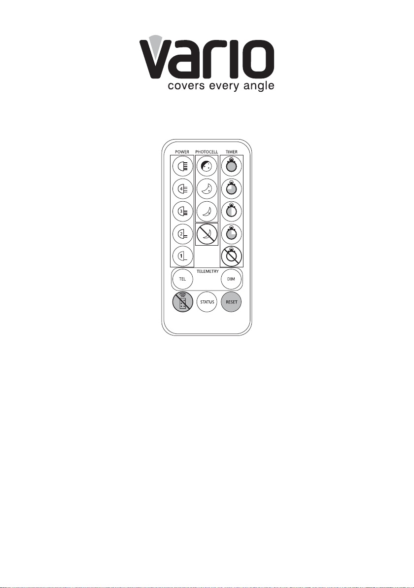
VARIO REMOTE CONTROL INSTRUCTIONS
Control features
1. LED Status Indicators,
Using the Remote and
Operating Modes
2. Power Adjust
3. Photocell Sensitivity
4. Wiring of Remote Switch
or Input (Telemetry Input)
4a.Telemetry – TEL –
Remote Switching
4b. Telemetry – DIM –
Remote Dimming
4c. Timer Function
5. LED Status Indicators -
Enable/Disable
6. Restore Factory Default
Settings & Stored Memory
7. Disable Remote Control
Set-up
8. Control Feature
Combinations
9. Mechanical Details and
Battery Information
10. Vario Remote Control Troubleshooting
1
Page 2

1. LED Status Indicators, Using the Remote and
Operating Modes
There are three, coloured LEDs visible on the base of the VARIO illuminator. The
three LEDs provide important operating and status information. The infra-red
receiver for the Remote Control commands is also on the base of the unit – and
the Remote Control should be pointed in this direction during programming.
Most functions respond immediately to pressing the required button – however
two functions require the button to be held for 4 seconds continuously to avoid
accidental programming:1.Restore Factory Default and 2.Disable Remote
Control Set-up. The Remote Control is designed to operate at distances upto
8 metres.
The status information provided by each of these LEDs differs depending on
which of the two operating modes the VARIO illuminator is in: (A) Programming
OR (B) Normal Operating
1A. Programming Mode
On powering up the illuminator, it automatically enters programming mode to allow
the user to adjust set-up and operation. The programming mode automatically
times out after 4 weeks or until the user actively disables the programming mode
- see ‘Disable Remote Control Set-up’ (section 7).
During Programming mode, the LEDs indicate the following status:
• SOLID GREEN: Power Applied
• FLASHING GREEN: Remote control IR receiver problem
• FLASHING AMBER: Indicates unit is in programming
mode
• SOLID AMBER: Indicates that a valid command
is being received
• SOLID RED: Internal LED Fault Detected
• FLASHING RED: Voltage supply problem detected
*(Please note – once the voltage problem has been corrected, the user must disable
remote control set-up or power the unit on and off to stop the red status LED flashing)
All functions of the Remote Control are available in Programming Mode.
2
Page 3

1B. Normal Operating Mode
During Normal Operating Mode (ie not in Programming Mode), the LEDs
indicate the following status:
• SOLID GREEN: Power Applied
• FLASHING GREEN: Remote control IR receiver problem
• SOLID AMBER: Voltage supply problem detected
**(Please note – once the voltage problem has been corrected, the user must disable
remote control set-up or power the unit on and off to extinguish the amber status LED)
• SOLID RED: Internal LED Fault Detected
The only function of the Remote Control available during Normal Operating
Mode is LED Status Indicators Enable/Disable (see section 5)
Factory Default: On initial power-up, illuminator automatically defaults into
programming mode. Programming mode automatically disabled after 4
weeks.
2. Power Adjust
The power output of the VARIO illuminator can be adjusted between 5 preset levels. To select the required light intensity use the buttons shown.
Factory default = 100% power.
100% of maximum
80% of maximum
60% of maximum
40% of maximum
20% of maximum
3
Page 4
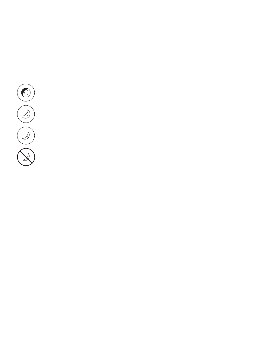
3. Photocell Sensitivity
There are three pre-defined levels to set the lux level threshold
at which the photocell turns the VARIO illuminator on/off.
To select the required sensitivity level use the buttons below.
Factory default = Medium Sensitivty:
10 Lux On, 30 Lux Off
25 Lux On, 50 Lux Off
10 Lux On, 30 Lux Off
5 Lux On, 15 Lux Off
Photocell disabled
IMPORTANT NOTE:
When the photocell disable button is selected this means that the
illuminator will turn on/off from a telemetry input, regardless of ambient
lighting conditions.
4
Page 5

4. Wiring of Remote Switch or Input (Telemetry Input)
Vario is supplied with a pair of Telemetry Input Wires – Orange and Purple –
which are designed to be used with a remote switch or input from an alarm
system, PIR detector, control room, Video Management system or camera
output. The input signal can be volt-free or TTL.
Volt-free input: Non Polarity Sensitive.Short circuit = Light On
TTL input: Orange = TTL+ve, Purple = TTL –ve (GND)
0V = Light On, 3V = Light Off
The Telemetry Input wires (Orange & Purple) are soldered together when
shipped from the factory to simulate a volt free input so the unit automatically
turns on/off via the photocell. Any remote input or switch should be connected
to these wires. Snip the end of the cable and then use the two-core cable as
normal.
Under normal operating conditions, a Telemetry Input will activate the
unit only at night provided that the Photocell detects low light conditions.
However, if the photocell is disabled, a Telemetry Input will activate the unit
regardless of ambient light conditions.
The remote input can be used in conjunction with the
illuminator in three different ways as described below:
1. TEL or 2.DIM or 3. TEL+TIMER. The mode of operation is selected by using
the Remote Control.
5
Page 6

4a. Telemetry – TEL (Remote Switching)
The TEL button should be selected if the illuminator is to be turned on/
off using a remote switch or input.
The TEL input can be used in various ways:
1. Turn the light on (night) and off (day) automatically via the photocell. This is the
standard factory setting – and no further action is required
2. Turn the light on and off from a remote switch or input
3. Used in conjunction with the Timer Function to turn the light on for a pre-defined
period of time. (see section 4c below).
Factory Default = Telemetry TEL Enabled.
See detailed wiring instruction - section 4.
4b. Telemetry - DIM (Remote Dimming)
The remote dimming feature allows the brightness of the VARIO
illuminator to be controlled remotely using the telemetry input wires.
Use the DIM button to select this function.
When the DIM function is selected, a telemetry input
into the illuminator will vary the brightness up and down.
When the telemetry input is first applied, it will start to dim the light and
will continue to do so whilst the telemetry input is active. When telemetry
input stops, the light level will stay where it was set. When the telemetry
input is activated for a second time, the light will start to brighten. This
will continue whilst the telemetry input is active. This activation and deactivation of the telemetry input will reverse the way the light is dimmed
(dim down and dim up), to allow the user to set to exactly the level
required. Please note that Remote Dim is disabled by pressing
TEL button (see 4a above).
After setting a specific light level using the DIM function, if Telemetry-DIM is
disabled and Telemetry-TEL enabled, the last power level set when using the DIM
function will be remembered and used by the system – unless a new power
adjust button is selected.
Factory Default =Telemetry DIM Disabled.
See detailed wiring instructions in section 4.
6
Page 7

4c. Timer Function
The timer function allows the VARIO illuminator to be triggered ON via a telemetry
input and remain on for a pre-defined period of time. There are four pre-defined
times and a timer disable function. To select timer fuction, first press and release
Telemetry TEL button, then secondly press duration of timer required as shown
below.Factory Default = Timer Disabled
If you wish to cancel timer period and have the unit operate under standard
telemetry conditions, press Timer Disabled.
30 minutes
10 minutes
3 minutes
1 minute
Timer disabled
5. LED Status Indicators - Enable/Disable
The three coloured LEDs visible on the base of the VARIO unit provide
important operating and status information. (See section 1 for
information on LED status indicator system).
This status indicator function can be switched on and off by pressing the STATUS
button. This is the only button that has two states. It is possible for this function to
be enabled/disabled even if programming mode has been disabled so the status
of the lamp can be checked at any time.
Factory default = LED Status Indicators Enabled.
7
Page 8

6. Restore Factory Default Settings & Stored
Memory
Once the VARIO unit has been programmed, the settings will be stored
in non-volatile (stored) memory. These settings are saved and reloaded
if the illuminator experiences loss of power. If you wish to restore the unit
back to its original factory default settings, this can be achieved when the unit is
in programming mode by pressing the RESET button. To activate this feature, the
button must be pressed continuously for at least 4 seconds. This is to avoid the
possibility of activating this feature accidentally.
The factory default settings are:
• Power Set to 100% of Maximum
• Photocell set to Medium Sensitivity Level:
10 Lux On, 30 Lux Off
• Timer Disabled
• Telemetry -TEL Enabled
• Telemetry Input wires soldered together for automatic photocell operation of unit
• Telemetry -DIM Disabled
• LED Status Indicators Enabled
• Programming Function Enabled for 4 weeks
7. Disable Remote Control Set-up
The security features implemented in the VARIO illuminator and
VARIO remote control are designed to ensure that the system
cannot be programmed by unauthorised personnel. The system
is automatically in programming mode once the illuminator is powered up.
Once the installer/user has finished programming the settings of the VARIO
illuminator, they can choose to lock-in these settings by pressing the ‘Disable
Remote Set-up’ button.
To activate this feature, the button must be pressed continuously for at
least 4 seconds. This is to avoid the possibility of activating this feature
accidentally. If remote set-up is not disabled from the Remote Control, the
illuminator will remain in programming mode for a pre-determined time of
4 weeks. After 4 weeks from power-up, remote set-up will be automatically
disabled.
8
Page 9

Please note: To enable programming mode again after remote set-up has
been disabled, the VARIO illuminator must be powered off (for at least 10
seconds) then on again - the illuminator will then automatically re-enter
programming mode.
We would normally recommend to disable remote set-up once you have finished
programming an individual VARIO illuminator and are satisfied that it is delivering
the required operating performance. This will help to avoid tampering and the
possibility of receiving commands when programming other units in close
proximity.
8. Control Feature Combinations
The following features can be altered / adjusted when programmed or used
together:
Power
Adjust
Timer
Photocell
Sensitivity
Remote
Dim
LED Status
Indicator
Power
Adjust
Timer
Photocell
Sensitivity
Remote
Dim
LED Status
Indicator
9
Page 10

9. Mechanical Details and Battery Information
Dimensions: 40 x 87 x 7.5 mm
Weight: 10g
Battery: CR2025
10. VARIO Remote Control Troubleshoot
(see VARIO instructions for troubleshooting of illuminator)
Ensure all tests are undertaken by a qualified, trained engineer. Ensure safe
working practices are followed at all times.
Troubleshoot
- Ensure no other strong Infra-Red source is pointing at the remote receiver
which is on the bottom of the unit.
- Ensure that there is a clear line of site between the unit and remote with no
possible obstructions.
- In bright sunlight, distance between the unit and remote may need to be
reduced.
- Switch STATUS button on /off to check the status of unit. If the unit is in
Programming Mode (indicated by FLASHING AMBER), a SOLID RED
LED indicates a problem with an internal LED, and a FLASHING RED LED
indicates an input voltage problem. * See section 1A for instructions on how
to extinguish red flashing LED.
- In Normal Operating Mode, SOLID AMBER denotes incorrect input voltage.
** See section 1B for instructions on how to extinguish solid amber LED.
SOLID RED indicates internal LED fault.
- If attempting to use Remote Control, ensure the unit is in programming mode
(FLASHING AMBER LED) If not in programming mode, re-power VARIO
illuminator. Turn power off for at least 10 seconds and then power on.
- Check battery on remote (CR2025)
If the remote is still not delivering the required performance, please contact
Raytec for further assistance on +44 (0)1670 520055 or +1 613 270 9990
for Americas.
10
Page 11

Vario Remote – Quick Set Up Instructions
1. At power up, the unit enters programming mode (FLASHING AMBER LED)
SOLID GREEN LED shows unit receiving power
FLASHING GREEN - Remote control IR receiver problem
SOLID AMBER LED shows unit receiving valid command
SOLID RED – Internal LED Fault Detected
FLASHING RED – Voltage supply problem detected
Unit stays in programming mode for 4 weeks or until remote control set-up disabled
2. If required: Adjust Power
Press 5 for 100% power, 4 for 80%, 3 for 60%, 4 for 40% and 2 for 20% power.
Factory Default = 100%
3. If required: Adjust Photocell Sensitivity
Press: Top Button for Low Sensitivity: 25 Lux On 50 Lux Off
2nd Button for Medium Sensitivity: 10 Lux On 30 Lux Off
3rd Button for High Sensitivity: 5 Lux On 15 Lux Off
Bottom button to disable photocell
Factory Default = Medium Sensitivity
Unit factory-set to turn on/off automatically from Photocell. Orange and Purple
Telemetry input wires are joined to mimic volt-free input (dry contact). Separate the
wires to use with remote switch or input.
4. Telemetry Input - General Wiring of Remote Switch or Input
Any external switch or input must be wired into Orange and Purple wires (Telemetry Input
Wires). These wires accept both volt-free input or TTL:
Volt-free input: Non Polarity Sensitive. Short circuit = Light On
TTL input: Orange = TTL+ve, Purple = TTL –ve (GND)
0V = Light On, 3V = Light Off
4a. TEL Select this option to turn lamp on/off remotely from a remote input or switch.
This is the factory default setting.
4b. DIM Select DIM to dim lamp remotely from an input or switch. First input reduces
power. Second input increases power … and so on.
4c.TIMER Press and release TEL – then select required period of time for unit to stay
on after Telemetry Input. Timings associated with each button shown in
section 4 of main instructions. To cancel Timer function press Timer Disable.
5. To turn LED Status Indicators on and off – Press STATUS button.
6. To restore all factory settings press RESET button. Defaults shown in section 6. This
button must be pressed continuously for 4 seconds to activate function.
7. Press this button to disable programming mode. Button must be depressed
for at least 4 seconds. Only do this when you are happy with the set-up and
installation of your unit.
11
Page 12

VR/14/06.1
12
UK / Europe
T: +44 (0) 1670 520055
F: +44 (0) 1670 819760
sales@rayteccctv.com
Americas
T: +1 613 270 9990
ussales@rayteccctv.com
www.rayteccctv.com
 Loading...