

Page 1
LUX URBAN
illuminators installation guide
This installation guide provides instructions for installing the RAYLUX
URBAN series of White-Light illuminators.
Installation Steps
1. Feed cable through bracket solution
2. Mount Illuminator
3. Mount PSU
4. Connect Illuminator to PSU
5. Connect Photocell to PSU
Set Up Steps
1. Locate unit(s) as advised in
lighting design
2. Position unit to provide illumination
down onto a scene
3. If using UBA48 or UBA32 model,
adjust the horizontal angle via
Adaptive illumination™
4. Tighten all fixings
Package Contents
1. Illuminator
2. Power Supply (PSU)
3. Illuminator cable (5m)
4. Photocell cable (5m)
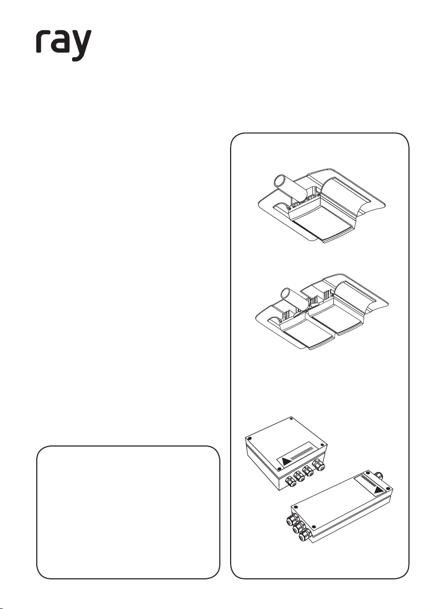
Overview
UBF Range
UBA Range
RAYLUX URBAN illuminators
GOLDEN RULES:
1. Ensure PSU lid orientation has
warning label in line with main
input glands
(see PSU diagram, right)
2. Ensure operating voltage is
correct for unit being installed
3. Ensure PSU is fully water tight
Version 1.1
WARNING
!
PSU
WARNING
!
1
Page 2
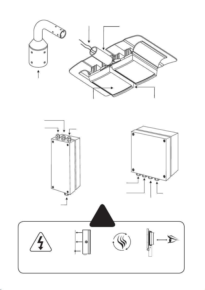
Bracket
(not supplied – see optional
bracketry – page 5)
LED output 2
LED output 1
LED output cable
5m (16.4ft)
Photocell input
Photocell mounted on
bracket, with 5m cable
Adaptive illumination boltLED illuminator
LED output 1
LED output 2
Mains input
Isolate mains before
removing cover
Specifications subject to change without notice. Installation to be carried out by suitable trained and qualified personnel.
2
Mount PSU to
flat surface or
inside column
!
Install in a well
ventilated area
Photocell input
Do not continually
stare at lamp
Mains input
1.5 m
Page 3
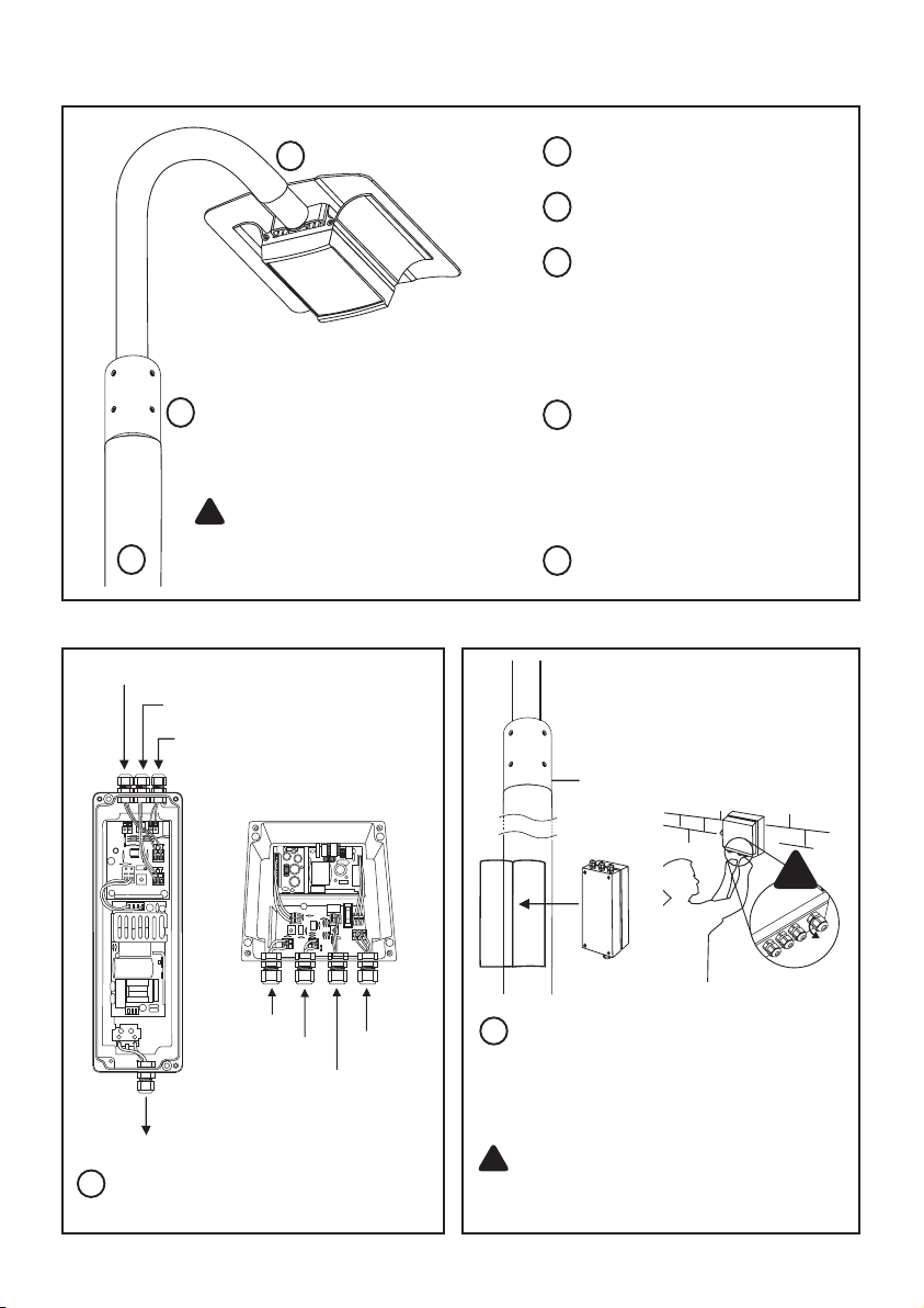
Installation
Feed cables through bracket
1
1
solution – see page 5
Mount and secure illuminator
2
Typically Column Mounted.
Mount PSU – Suitable for
3
inside most general lighting
columns (excluding UBA48)
can also be mounted
externally. If external ensure
glands are facing down.
2
3
LED output 1
LED output 2
Photocell input
Mains input
4
PSU connections.
!
CAUTION: Red = +ve
Black = -ve
(polarity sensitive)
(UBA48 Model only)
LED output 1
LED output 2
Mains input
Photocell input
Connect Illuminator to PSU:
4
Installers can extend or
reduce lead length using
appropriate cable and
weather proof box. Contact
Raytec.
5
Connect Photocell to PSU.
Column
5
UBA48 PSU needs to be mounted to a
wall or pole and then connected to the
mains. For all other Urban models, the
slimline PSU will be mounted inside the
column and connected to the mains.
!
CAUTION: Ensure cable glands
and PSU lid are water tight by
tightening the fixings
!
3
Page 4
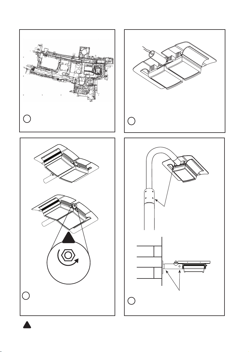
Set Up
1
Locate unit(s) as advised in
lighting design
Position unit to provide illumination
2
down onto a scene
!
Max x2 +max
5% uplift
3
If using UBA48 or UBA32 model,
adjust the horizontal angle via
Adaptive illumination™
!
CAUTION: Do not fully loosen AI bolt.
Note: Power adjust available if required (see PSU diagrams, pages 8-9)
4
Tighten all fixings
4
Page 5

Technical Drawings (Not to scale)
Standard Bracketry
UBF Range UBA Version
• Tube outreach 125mm
• o/d (outside diameter) 33.7
• i/d (inside diameter) 28
Optional Bracketry
Wall Bracket
• Finished in Silver
• o/d (outside diameter) 42.4
• i/d (inside diameter) 34.4
Top Stub Bracket
•Arm o/d 42.4, i/d 39.4
•Bracket Cup o/d 88.9, i/d 84.9
• Fits 76 Spigot
• Twin Version Available
Hockey Bracket
• Arm o/d 42.4, i/d 39.4
• Bracket Cup o/d 88.9, id 84.9
• Fits 76 Spigot
• Twin Version Available
5
Page 6

Technical Specifications
URBAN Series
UBA48 UBA32 UBF24 UBF16 UBF8
Consumption <80W <50W <40W <25W <15W
Lumen Output* 4700 3100 2350 1600 800
Colour Temp** 6500K 6500K 6500K 6500K 6500K
CRI** 74 - 80+ 74 - 80+ 74 - 80+ 74 - 80+ 74 - 80+
Temp -50˚C to +50˚C -50˚C to +50˚C -50˚C to +50˚C -50˚C to +50˚C -50˚C to +50˚C
Colour
Angles Various Various Various Various Various
Bracket*** Side Entry Side Entry Side Entry Side Entry Side Entry
IP IP66 IP66 IP66 IP66 IP66
Weight
(inc. PSU)
Silver
other RAL options
available
5kg 4kg 3kg 2.5kg 1.5kg
Silver
other RAL options
available
Silver
other RAL options
available
Silver
other RAL options
available
Silver
other RAL options
available
OPERATING VOLTAGE: All Raytec units are supplied complete with a dedicated (Universal
100-240V AC auto sensing) current controlled PSU c/w adjustable photocell, power and
telemetry input.
Note: Full independent photometry available on request.
* Lumen output depends upon final lens selection. Lumen output shown based on average between 10 and 50 degree angles.
** Cool White as standard - Warm White options available. CRI published reflects range between Cool and Warm White.
*** See page 5 for optional bracketry.
6
Page 7

PSU Specifications
URBAN Series PSU
UBA48 UBA32 UBF24 UBF16 UBF8
Input
Fuse 2.5A antisurge 2.5A anti-surge 2.5A anti-surge 1A anti-surge 1A anti-surge
Typical Output
(Standard)
Adjustable Power 10% - 100% 10% - 100% 10% - 100% 10% - 100% 10% - 100%
Weight
Dimensions
L x W x D
AC-100-240
universal<80W
4.2A @ 14V 2.8A @ 14V 2.1A @ 14V 1.4A @ 14V 0.7A @ 14V
1.85kg
(4.1 lbs)
160x160x81mm
(6.3x6.3x3.2”)
AC-100-240
universal<40W
0.7kg
(1.5 lbs)
248x78x55mm
(9.7x3x2.1”)
AC-100-240
universal<40W
0.7kg
(1.5 lbs)
248x78x55mm
(9.7x3x2.1”)
AC-100-240
universal<20W
0.7kg
(1.5 lbs)
248x78x55mm
(9.7x3x2.1”)
AC-100-240
universal<10W
0.7kg
(1.5 lbs)
248x78x55mm
(9.7x3x2.1”)
Power Supply Features
STANDARD PSU
• Input: Universal 100-240V
AC auto-sensing
• Output: Low Voltage
(~14V Current Controlled)
• -50 to +50 C
• IP67
• Telemetry (Volt Free)
• Integrated Photocell (Adjustable)
• Power Adjustable
OPTIONAL PRO PSU
(UBA48 ONLY)
As above plus:
• 12V (1amp) DC Output
• Photocell Following Contact
• Allows Pro IQ module to be tted
PRO SERIES PSU PLUG IN
MODULE:
(UBA48 ONLY)
PRO IQ
• Remote Illumination Adjust
(Dim and Boost)
• Energy Saving Setting
• Deterrent setting
• Timer options
7
Page 8

Power Supply Diagrams (Not to scale)
STANDARD PSU
URBAN UBA48 Model
Telemetry Input
- requires zero volt,
latched input
Power Adjust
LED Output x2
(Polarity Sensitive)
8
Photocell Input
Photocell Sensitivity
Mains Input
100V to 230V AC
Auto-Sensing
Page 9

SLIMLINE PSU
URBAN UBA32, UBF24, UBF16, UBF8 Models
LED output 2
LED output 1
Power Adjust
Photocell input
Photocell Sensitivity
Mains Input
9
Page 10

Trouble Shooting
Ensure all tests are undertaken by a qualified, trained engineer.
Ensure safe working practices are followed at all times
Step 1: Basics
• Check polarity of WHITE-LIGHT Lamp connection
red=+ve, black=-ve
• Check telemetry link is in
• Check photocell is working
• Check power setting pot fully clockwise
• Check mains input
• Check fuse intact
If OK…
Step 2: Lamp Test
Check voltage of lamp o/p approx 14V
Check current of lamp – see instructions for correct current setting
To check lamp current (this must be done while both LED panels
are connected to the PSU) remove +ve LED from both lamp supply
cables and connect multimeter set to 10A current in line with the
lamp. [One lead of multimeter in common (COM), other lead into
10A socket of multimeter; set multimeter to 10A readings]. Refer to
PSU Specications for correct current settings, see pages 7.
10
Page 11

Step 3: Call Raytec for further assistance
Note down:
• Model and serial number of illuminator
If the Raytec lamp is still not delivering the required performance,
please contact us for further assistance.
11
Page 12

UII/10/9.1
UK / Europe
T: +44 (0) 1670 520055
F: +44 (0) 1670 819760
sales@rayteccctv.com
Americas (Toll Free)
T: +1 888 505 8335
ussales@rayteccctv.com
www.rayteccctv.com
 Loading...