

Page 1
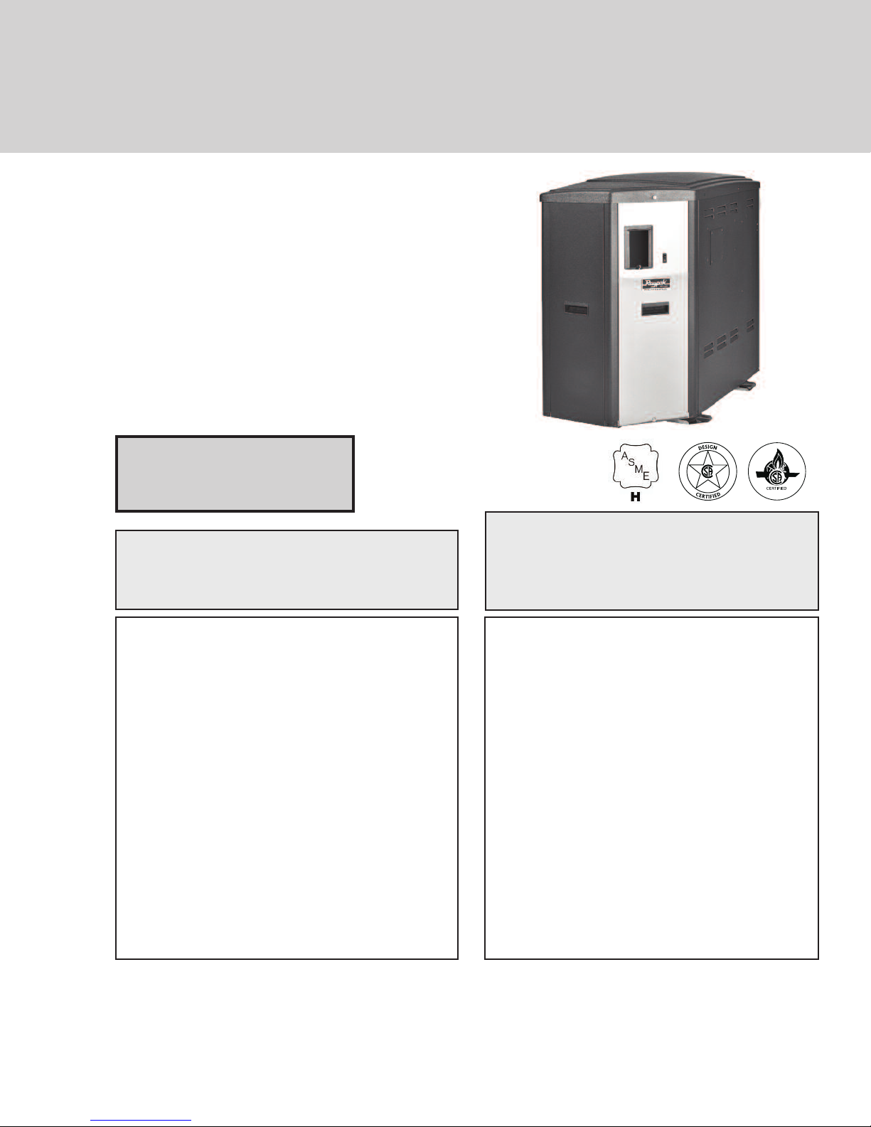
INSTALLATION & OPERATING
INSTRUCTIONS
X94
Professional
Gas-Fired
Pool & Spa
Heater
Low NOx Model
SR-410
WARNING: If the information in these instructions
are not followed exactly, a fire or explosion may
result causing property damage, personal injury or
death.
Do not store or use gasoline or other flammable
vapors and liquids or other combustible materials in
the vicinity of this or any other appliance. To do so
may result in an explosion or fire.
WHAT TO DO IF YOU SMELL GAS:
Do not try to light any appliance.•
Do not touch any electrical switch; do not use•
any phone in your building.
Immediately call your gas supplier from a•
neighbor’s phone. Follow the gas supplier’s
instructions.
If you cannot reach your gas supplier, call the•
fire department.
Installation and service must be performed by a
qualified installer, service agency or the gas supplier.
AVERTISSEMENT: Assurez-vous de bien suivre
les instructions données dans cette notice pour
réduire au minimum le risqué d’incendie ou
d’explosion ou pour éviter tout dommage matériel,
toute blessure ou la mort.
Ne pas entreposer ni utilizer d’essence ou ni
d’autres vapeurs ou liquids inflammables à proimité de cet appareil ou de tout autre appareil.
CE FAIRE SI VOUS SENTEZ UNE ODEUR
DE GAS:
Ne pas tenter d’allumer d’appareil. •
Ne touchez á aucun interrupteur; ne pas vous•
server des téléphones se trouvant dans la
bâtiment.
Appelez immédiatement votre fournisseur de•
gaz depuis un voisin. Suivre les instructions
du fournisseur.
Si vous ne pouvez rejoinder le fournisseur,•
appelez le service es incendies.
L’installation et l’entretien doivent être assurés par
un installeur qualifié ou par le fournisseur de gaz.
This manual should be maintained in legible condition and kept adjacent to the heater or in a safe place for future
reference.
Catalog No. 6000.66 Effective: 10-15-14 Replaces: NEW P/N 241494 Rev. 1
Page 2

WATER CHEMISTRY
(Corrosive water voids all warranties)
For your health and the protection of your pool equipment, it is essential that your
water be chemically balanced. The following levels must be used as a guide for balanced water.
Recommended Level(s) Fiberglass Pools Fiberglass Spas
Water Temp. Deg. F
(Deg. C)
68 to 88
(20 to 31)
89 to 104
(32 to 40)
Other Pool & Spa
Types
68 to 104
(20 to 40)
pH 7.3 to 7.4 7.3 to 7.4 7.6 to 7.8
Total Alkalinity (PPM) 120 to 150 120 to 150 80 to 120
Calcium Hardness (PPM) 200 to 300 150 to 200 200 to 400
Salt (PPM) 4500 MAXIMUM 4500 MAXIMUM 4500 MAXIMUM
Free Chlorine (PPM)* 2 to 3 2 to 3 2 to 3
Total Dissolved Solids (PPM) 3000 MAXIMUM** 3000 MAXIMUM** 3000 MAXIMUM**
* Free Chlorine MUST NOT EXCEED 5 PPM!
** In salt water chlorinated pools, the total TDS can be as high as 6000 ppm.
• Occasional chemical shock dosing of the pool or spa water should not damage the
heater providing the water is balanced.
• Automatic chemical dosing devices and salt chlorinators are usually more efficient
in heated water, unless controlled, they can lead to excessive chlorine level which
can damage your heater, and which is not covered under warranty. A check
valve should be installed between the heater outlet and a chlorinator or other chemical dosing device.
• Further advice should be obtained from your pool or spa builder, accredited pool
shop, or chemical supplier for the correct levels for your water.
Rev. 1 reflects the following:
Changes to: None
Additions: None
Deletions: None
2
Page 3

CONTENTS
2 Water Chemistry
4 WARNINGS
4 Pay Attention to These Terms
5 PART ONE
OWNER'S OPERATING INSTRUCTIONS
5 SECTION 1
START-UP PROCEDURES
6 SECTION 2
CAUTION
6 SECTION 3
MAINTENANCE & CARE PROCEDURES
7 Lighting & Shutdown Instructions
8 Pool & Spa Water Chemistry
8 Automatic Chlorinators & Chemical Feeders
8 Cold Weather Operation
8 Winterizing the Pool & Spa Heater
9 PART TWO
INSTALLATION & SERVICE INSTRUCTIONS
9 SECTION 1
RECEIVING EQUIPMENT
10 SECTION 2
GENERAL SPECIFICATIONS
10 SECTION 3
INSTALLATION INSTRUCTIONS
10 Code Requirements
11 Clearances
11 Outdoor Heater Installation
13 Florida Building Code
14 Indoor Heater Installation
14 Specifications and Dimensions
16 Combustion and Ventilation Air
16 Direct Vent
17 Venting
18 Support of Vent Stack
18 Vent Terminal Location
19 Venting Installation Tips
19 Condensate Management
20 Venting Configurations
20 Vertical Venting (Category IV)
22 Horizontal Through-the-Wall Venting
(Category IV)
23 Direct Vent - Horizontal
25 Direct Vent - Vertical
25 Outdoor Installation
26 Gas Supply Connections
26 Supply Pressures
26 Gas Pressure Adjustment Locations
26 Pipe Sizing For Gas Connections
26 Heat Exchanger Pressure Drop Tables
27 Flow Rates
27 External Automatic Bypass Valve
27 External Auxiliary Bypass Valve
27 Auxiliary Bypass Valve Adjustment
27 Pressure Relief Valve Piping
28 Electrical Wiring
28 Transformer Wiring
29 Plumbing—Water Connections
29 Loose Plumbing Parts Setup
30 Recommended Plumbing Setups
32 Wiring Diagram
33 SECTION 4
SERVICING INSTRUCTIONS
33 General Location of Controls
34 Control Adjustments
34 Control Panel Removal
35 Thermostat Operation - Direct Spark Board
36 Installer Setup Mode
38 Status and Diagnostics
40 Remote Control Installation and Operation
40 Remote Operation
40 Activating the Remote
41 Remote Control Wiring
41 2-Wire Remote Control
41 3-Wire Remote Control
42 Time Clock / Fireman’s Switch
42 High Limits
42 Flow Switch
42 Blocked Vent Switch
42 Adjusting Valve Manifold Pressure
43 Visual Inspection
43 Electrical
43 Orifice Removal
43 Combustion Settings
43 Igniter Removal
43 SECTION 5
TROUBLESHOOTING
44 Mechanical
45 Control Logic - Flow Chart
46 SECTION 6
REPLACEMENT PARTS
46 Illustrated Parts List
48 Part Numbers
50 Important Instructions for the
Commonwealth of Massachusetts
51 Installer Setup Record
3
Page 4
WARNINGS—Pay Attention to These Terms
DANGER:
WARNING:
CAUTION:
NOTE:
DANGER: Failure to properly vent the heater to the
outdoors as outlined in the Venting section of this
manual can result in unsafe operation of the heater.
To avoid the risk of fire, explosion, or asphyxiation
from carbon monoxide, never operate this heater
unless it is properly vented and has an adequate air
supply for proper operation. Be sure to inspect the
vent system for proper installation at initial start-up;
and at least annually thereafter. Refer to the
Maintenance section of this manual for more
information regarding vent system inspections.
DANGER: Make sure the gas on which the heater
will operate is the same type as that specified on the
heater rating plate.
DANGER: When servicing or replacing components
that are in direct contact with the water, be certain
that:
• There is no pressure in the heater. (Pull the release
on the relief valve. Do not depend on the pressure
gauge reading).
• The heater water is not hot.
• The electrical power is off.
WARNING: All venting types must be of the same
material or product throughout the entire exhaust
installation to ensure proper securing and sealing.
WARNING: Altering any Raypak pressure vessel
by installing replacement heat exchangers, tube
bundle headers, or any ASME parts not
manufactured and/or approved by Raypak will
instantly void the ASME and/or CSA ratings of the
vessel and any Raypak warranty on the vessel.
Altering the ASME and/or CSA ratings of the vessel
also violates national, state, and local approval
codes.
WARNING: This product must be installed by a
licensed plumber or gas fitter when installed within
the Commonwealth of Massachusetts.
Indicates the presence of immediate hazards which will cause severe
personal injury, death or substantial property damage if ignored.
Indicates the presence of hazards or unsafe practices which could cause
severe personal injury, death or substantial property damage if ignored.
Indicates the presence of hazards or unsafe practices which could cause
minor personal injury or product or property damage if ignored.
Indicates special instructions on installation, operation, or maintenance which
are important but not related to personal injury hazards.
WARNING: Both natural gas and propane have an
odorant added to aid in detecting a gas leak. Some
people may not physically be able to smell or
recognize this odorant. If you are unsure or
unfamiliar with the smell of natural gas or propane,
ask your local gas supplier. Other conditions, such
as "odorant fade," which causes the odorant to
diminish in intensity, can also hide, camouflage, or
otherwise make detecting a gas leak by smell more
difficult.
WARNING: UL recognized fuel gas detectors are
recommended in all enclosed propane and natural
gas applications wherein there is a potential for an
explosive mixture of fuel gas to accumulate and their
installation should be in accordance with the
detector manufacturer's recommendations and/or
local laws, rules, regulations, or customs.
WARNING - CALIFORNIA PROPOSITION
65: This product contains chemicals known to the
State of California to cause cancer, birth defects or
other reproductive harm.
WARNING: Do not install within 3 feet of a heat
pump or an outdoor condensing unit. Strong air
intake from this type of equipment can disturb the
combustion process and cause damage or personal
injury.
WARNING: Do not use this heater if any part has
been under water. Immediately call a qualified
service technician to inspect the heater and to
replace any part of the control system and any gas
control which has been under water.
AVERTISSEMENT: N’utilisez pas cet appareil s’il
a été plongé dans l’eau, même partiellement. Faites
inspecter l’appareil par un technicien qualifié et
remplacez toute partie du système de contrôle et
toute commande qui ont été plongés dans l’eau.
4
Page 5
PART ONE
OWNER'S OPERATING INSTRUCTIONS
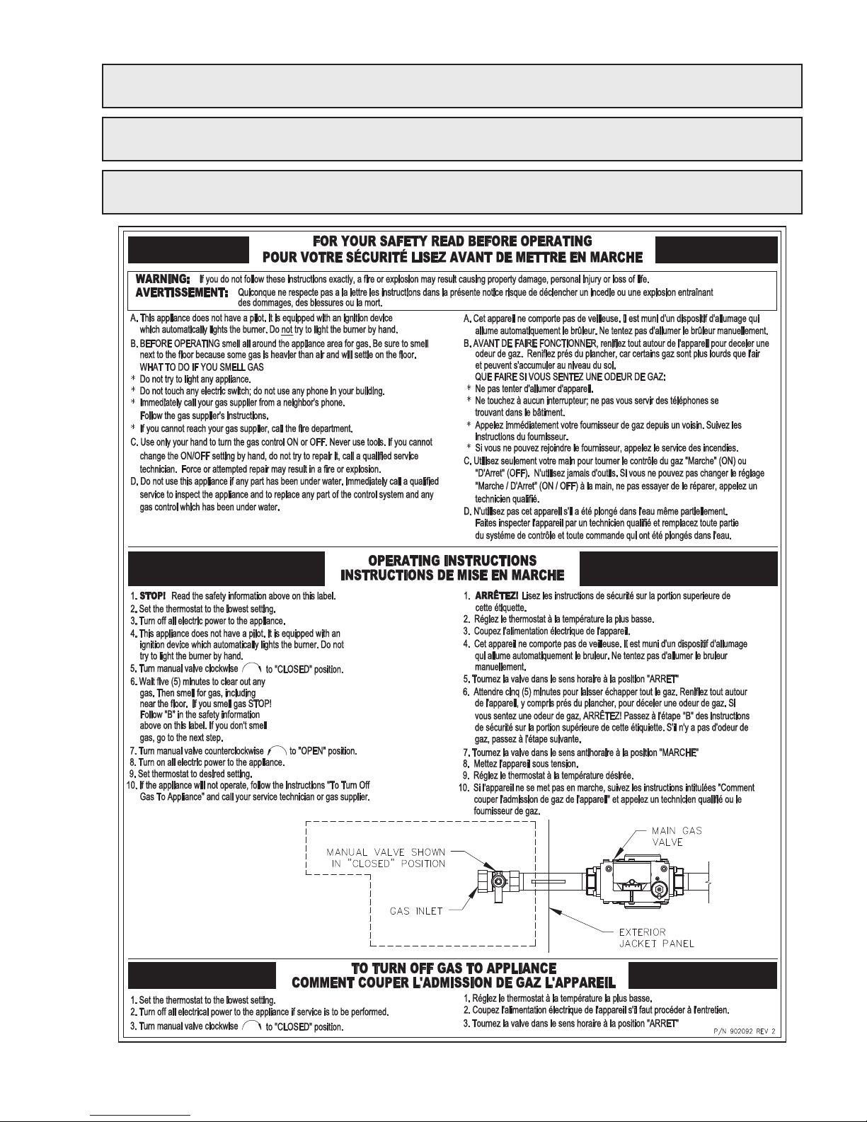
FOR YOUR SAFETY - READ BEFORE OPERATING
WARNING: IF YOU DO NOT FOLLOW THESE INSTRUCTIONS EXACTLY, A FIRE OR EXPLOSION MAY
RESULT, CAUSING PROPERTY DAMAGE, PERSONAL INJURY OR LOSS OF LIFE.
INTRODUCTION
Your pool/spa heater has been designed for years of safe and reliable pool/spa water heating. It is available with
electronic ignition. This manual provides installation, operation, maintenance, and service information for these
heaters.
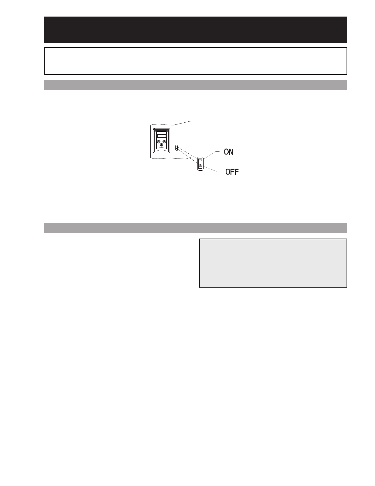
With proper installation and setup, operation of the heater is straightforward. The upper front panel of the heater
contains the control center that allows you to turn the heater On or Off, select the mode of operation, and adjust
the temperature settings for the pool or spa. The temperature range is factory set from 50°F (18°C) to 104°F
(40°C). See figure above for location of toggle switch to turn the heater On and Off. Section 4 of this manual contains more details about the use of the controls in the Control Adjustments subsection (starting on page 34).
SECTION 1 - START-UP PROCEDURE
1. Clean air louvers of dust, lint and debris.
2. Keep heater area clear and free from com-
bustibles, flammable liquids and chemicals.
3. Remove the top panel by removing the two screws
at the rear of the heater and the knurled screw
above the control panel. Lift the top panel off and
set it aside. Visually verify that the filter box intake
is not obstructed and that the filter is clean.
4. Water must be flowing through the heater during
operation. Ensure that the system is filled with
water and the pump is operating. Double check
for any water leaks.
5. Purge air from the gas line. Insufficient purging
may keep the heater from lighting on the first try.
6. Double check gas connections, make sure no
leaks are present. Use soapy water to inspect.
7. Double check incoming electrical power, verify suf-
ficient supply of 120V/1ph/60Hz power to the
heater.
8. If installed indoors, make sure flue gases are vent-
ed properly, and that combustion and makeup air
openings are adequate and clear of obstruction.
9. Verify that the fuel type of the unit matches the
supply gas.
10. Locate and turn the manual gas valve ON.
11. Locate the plugged bleedle valve on the pipe
downstream of the gas valve.
12. Remove the bleedle plug and connect a manome-
ter capable of reading up to -24" WC (-6 kPa).
CAUTION: The X94 manifold and blower suction
pressures measured at this point are negative, and
can be as high as -19" WC (-4.73 kPa) when the
blower is at full speed and the gas valve is closed.
Verify that manometers are rated appropriately and
set up to take measurements of this magnitude.
13. Locate and flip the display lid upwards.
14. Turn the heater on, by pressing the ON/OFF toggle switch on the front display.
15. Set the mode to either SPA or POOL. For installations utilizing the Raypak Expanded Function
Board refer to the installation and set up instructions on page 36-37 to set up the pump, valve and
auxiliary functions prior to firing the heater.
16. If the set point is higher than the current temperature, the heater will begin its startup sequence.
17. The ignition control will verify that the blower relay
is open before starting the blower. Once proven
open, the blower will be powered to start the ignition sequence.
18. Once the blower relay proves, a 45 second prepurge period will begin to purge the combustion
chamber.
19. Once the pre-purge period ends, the igniter will
begin to spark just prior to the gas valve opening.
The gas valve will open for a 4 second trial for ignition. If flame is proven, the heater will operate to
meet heat demand. If flame is not proven, the
5
Page 6

heater will enter a post-purge period and then retry
the ignition cycle or lockout, depending on the
heater configuration.
20. Once gas is flowing, the manometer reading will
drop to -0.2” +/- 0.1" WC (-0.05 +/- 0.02 kPa) at
ignition and will read -2.0" +/- 0.5" WC
(-0.5 +/- 0.12 kPa) at high fire (7500 +/- 50 RPM
fan speed). See the instructions on page 42 for
adjusting the valve manifold pressure if the reading is not within tolerance.
21. Visually check through the sight glass that the
heater is on and heating. An orange glow indicates that the heater is running. At high fire, the
flame should be visible. The flame should be blue
in color with some orange streaks when the
air/fuel ratio is correct. See the visual inspection
instructions on page 43 for additional information.
22. Remove the manometer and replace the bleedle
plug.
23. Reinstall top panel, install the two screws at the
rear and knurled screw above the control panel.
24. Feel the inlet and outlet pipes. Outlet pipe should
be 10ºF to 20ºF (6ºC to 11ºC) warmer than the
inlet. It should not be hot.
6. Persons taking medications which induce drowsiness, such as tranquilizers, antihistamines, or anticoagulants, should not use spas or hot tubs.
SECTION 3 - MAINTENANCE AND
CARE PROCEDURES
WARNING: Check the heater for possible rodent
nests after long periods of non-use.
To be followed one month after start-up and then semiannually.
1. Inspect and operate all controls, gas valve and
pressure relief valve.
2. On indoor heaters, clean room intake openings to
ensure adequate flow of combustion and ventilation air.
CAUTION: Combustion air must not be contaminated by corrosive chemical fumes which can damage the heater and void the warranty.
SECTION 2 - CAUTION
Elevated water temperature can be hazardous. The
U.S. Consumer Product Safety Commission has these
guidelines:
1. Spa water temperatures should never exceed
104°F (40°C). A temperature of 100°F (38°C) is
considered safe for a healthy adult. Special caution
is suggested for young children.
2. Drinking of alcoholic beverages before or during
spa or hot tub use can cause drowsiness which
could lead to unconsciousness and subsequently
result in drowning.
3. Pregnant Women Beware! Soaking in water over
102°F (39°C) can cause fetal damage during the
first three months of pregnancy resulting in the birth
of a brain-damaged or deformed child. Pregnant
women should stick to the 100°F (38°C) maximum
rule.
4. Before entering the spa or hot tub, users should
check the water temperature with an accurate thermometer; spa or hot tub thermostats may err in regulating water temperatures by as much as 4°F
(2.2°C).
5. Persons with a medical history of heart disease, circulatory problems, diabetes, or blood pressure
problems should obtain a physician's advice before
using spas or hot tubs.
3. Keep area around heater clear and free from combustible materials, gasoline and other flammable
and corrosive vapors and liquids.
4. Visually inspect the intake air filter for damage or
obstruction. If the filter is visually good, test the filter. If the intake suction reading when operating at
7500 RPM is more negative than -0.5" WC
(-0.1 kPa) replace the filter.
Fig. 1: Air Intake Pressure Measurement Location
IF HEATER WILL NOT FIRE:
If you have no electrical power, it may be that your
"circuit breaker" has tripped. Try re-setting it.
If you have electrical power but the heater will not fire
check the following or see Troubleshooting section:
6
Page 7
WARNING: Should overheating occur or the gas supply fail to shut off, turn off the manual gas control to the
heater.
AVERTISSEMENT: En cas de surchauffe ou si l’alimentation en gaz ne s’arrête pas, fermez manuellement
le robinet d’arrêt de l’admission de gaz.
CAUTION: Propane gas is heavier than air and will settle on the ground. Since propane can accumulate in
confined areas, extra care should be exercised when lighting propane heaters.
7
Page 8

1. The time clock must be in the "ON" position.
COLD WEATHER OPERATION
2. Your pump strainer basket may be full. If so,
remove debris.
3. Your water filter may be dirty. If so, backwash or
clean filter. (To tell if your filter is dirty, look to see
if the filter pressure will be higher than usual).
4. The pump may have lost its prime and be running
dry. Check the pressure on the filter. If there is no
pressure; then you are not moving water (or your
gauge is broken). Try to get the pump to run at its
normal flow rate.
POOL & SPA WATER CHEMISTRY
Chemical imbalance can cause severe damage to
your heater and associated equipment. Maintain
your water chemistry according to the chart on page 2.
If the mineral content and dissolved solids in the water
become too high, scale forms inside the heat exchanger tube, reducing heater efficiency and damaging the
heater. If the pH drops below 7.2, this will cause corrosion of the heat exchanger and severely damage the
heater. Heat exchanger damage resulting from
chemical imbalance is not covered by the warranty.
AUTOMATIC CHLORINATORS AND
CHEMICAL FEEDERS
All chemicals must be introduced and completely diluted into the pool or spa water before being circulated
through the heater. Do not place sanitizing chemicals
in the skimmer. High chemical concentrations will
result when the pump is not running (e.g. overnight).
Chlorinators must feed downstream of the heater and
have an anti-siphoning device to prevent chemical
back-up into the heater when the pump is shut off. A
check valve should be installed between the heater
outlet and the chlorinator.
See plumbing diagrams on page 30 and 31.
IMPORTANT FREEZE INFORMATION
MODERATE CLIMATE: Heater operation can continue during short-term cold spells. When temperatures are between 0°F (-17ºC) and 32°F (0ºC), flow
(continuous pump operation) must be maintained.
CAUTION: Do not use the heater to maintain water
temperatures just above freezing or for freeze protection. When heater is used during freezing weather,
care must be taken to avoid freeze-ups. Continuous
pump operation is a must. Additional protection may
be required. The heater is not warranted against
freeze-ups.
COLD CLIMATE: Prolonged operation with water
temperatures below 50°F (10ºC) is not recommended. When starting the heater with water temperatures
below 50°F (10ºC), operate the heater continuously
until higher temperatures are reached. Operating the
heater for prolonged periods with pool water below
50°F (10ºC) can seriously damage the heater, and is
not covered by the warranty.
For cold climate areas, please follow the winterizing
procedures listed.
WINTERIZING THE POOL & SPA HEATER
Heaters installed outdoors in freezing climate areas
may be shut down for the winter. Observe the following procedure for winterizing the heater:
1. Turn off gas valve, manual gas valve, and electrical supply to the heater.
2. Disconnect the field supplied condensate drain line
from the condensate trap located below the
inlet/outlet water connections.
3. Remove the access panel below the inlet/outlet
water connections and connect a hose to the drain
valve. Direct the hose discharge to a safe drainage
location.
NOTE: High chemical concentrates from feeders and
chlorinators that are out of adjustment will cause rapid
corrosion of the heat exchanger. Such damage is
not covered under the warranty.
4. Open the drain valve and pull the PRV handle or
open the union at the water outlet connection to
allow the heater to drain.
5. Close the drain valve and disconnect the hose.
6. Remove the cap from the condensate trap.
Disconnect, remove and drain the condensate trap
and then re-intstall it.
7. Re-install the lower access panel and re-attach the
condensate drain line to the trap.
8
Page 9

PART TWO
INSTALLATION AND SERVICE INSTRUCTIONS
SECTION 1 - RECEIVING EQUIPMENT
The manufacturer recommends that this manual be reviewed thoroughly before installing your pool/spa heater.
If there are any questions that this manual does not answer, please contact the factory or your local representative.
On receipt of your equipment it is suggested that you visually check for external damage to the carton. If the
carton is damaged, a note should be made on the Bill of Lading when signing for the equipment. Remove the
heater from the carton. If it is damaged, report the damage to the carrier immediately. Save the carton.
These items are shipped inside a box in the carton with the heater:
STANDARD UNIT
1. Bypass assembly P/N 077087 6. (4) Mounting screws and (4) washers
2. Bonding lug with mounting screw 7. (2) Bird screens (not shown)
3. 4" Intake air adapter (not shown) 8. 4" Sch 40 PVC Tee and
4. PVC/Polypropylene/Stainless Steel 5" (127 mm) L x 4" diameter Sch 40
vent adapter P/N 502117 PVC vent pipe P/N 077450
5. (2) 2" CPVC Plugs (not shown) 9. (2) 2” CPVC Swivel Unions P/N 502142
Be sure that you receive the number of packages indicated on the Bill of Lading.
When ordering parts, you must specify the model and serial numbers of the heater. See below for location of
serial number. When ordering under warranty conditions, you must also specify date of installation.
9
Page 10
SECTION 2 - GENERAL SPECIFICATIONS
These heaters are design-certified and tested under the latest requirements of the ANSI Z21.56 / CSA 4.7
Standard for Gas-Fired Pool Heaters. All heaters can be used either indoor or outdoors.
Ambient Temperature Rating of Heater Components
Electronics and controls -32°F to +175°F (-35.5ºC to +79.5ºC)
Condensate drains and trap* +32ºF to 175ºF (0ºC to 79ºC)
*The heater must be in a non-freezing environment to operate properly. Frozen condensate may damage components. Winterize the heater prior to prolonged exposure to freezing temperatures.
Rated inputs are suitable for up to 4,500’ (1,371 m) elevation. At elevations above 4500 feet (1,371 m) the input
will be reduced by approximately 4% for each 1,000’ (304.8 m) above sea level as high elevation reduces gas
and air density.
SECTION 3 - INSTALLATION INSTRUCTIONS
CALIFORNIA PROPOSITION 65 WARNING: This product contains chemicals known to the State of
California to cause cancer, birth defects or other reproductive harm.
WARNING: This unit contains refractory ceramic fiber (RCF) insulation in the combustion chamber. RCF, as
manufactured, does not contain respirable crystalline silica. However, following sustained exposure to very
high temperatures (>2192°F), the RCF can transform into crystalline silica (cristabolite). The International
Agency for Research on Cancer (IARC) has classified the inhalation of crystalline silica (cristabolite) as carcinogenic to humans.
When removing the burner or heat exchanger, take precautions to avoid creating airborne dust and avoid
inhaling airborne fibers. When cleaning spills, use wet sweeping or High Efficiency Particulate Air (HEPA)
filtered vacuum to minimize airborne dust. Use feasible engineering controls such as local exhaust ventilation
or dust collecting systems to minimize airborne dust. Wear appropriate personal protective equipment
including gloves, safety glasses with side shields, and appropriate NIOSH certified respiratory protection, to
avoid inhalation of airborne dust and airborne fiber particles.
IMPORTANT NOTICE
These instructions are intended only for the use by qualified personnel, specifically trained and experienced in the installation of this type of heating equipment and related system components. Installation
and service personnel may be required by some states to be licensed. If your state is such, be sure your contractor bears the appropriate license. Persons not qualified shall not attempt to repair this equipment according
to these instructions.
WARNING: Improper installation, adjustment, alteration, service or maintenance may damage the equipment, create a hazard resulting in asphyxiation, explosion or fire, and will void the warranty.
CODE REQUIREMENTS
NOTE: The heater should not be located in an area where possible water leakage will result in damage to the
area adjacent to the heater or to the structure. When such locations cannot be avoided, it is recommended
that a suitable drain pan, with adequate drainage, be installed under the heater. The pan must not restrict combustion air flow.
Installation must be in accordance with local codes, or, in the absence of local codes, with the latest edition of
the National Fuel Gas Code, ANSI Z223.1/NFPA54 and National Electrical Code, ANSI/NFPA 70, and for
Canada, the latest edition of CAN/CSA-B149 Installation Codes, and Canadian Electrical Code, CSA C22.1
Part1 and Part 2.
10
Page 11
CLEARANCES
ALL HEATERS
For clearances from combustible surfaces, see the
chart below.
CLEARANCE FROM
COMBUSTIBLE CONSTRUCTION
When installed according to the listed minimum clearances from combustible construction, the pool heater
can still be serviced without removing permanent
construction around the heater.
INDOOR INSTALLATIONS:
Top - 24” (609.6 mm) Back - 1” (25.4 mm)
Front - Alcove (Open) Right Side - 1” (25.4 mm)
Vent - 1” (25.4 mm) Left Side - 1” (25.4 mm)
Floor* - 0” (0 mm)
However, for ease of servicing, Raypak recom-
mends a clearance of at least 24” (609.6 mm) in the
front and back. This will enable the heater to be serv-
iced in its installed location, without movement or
removal of the heater.
NOTE: The heater must be installed in a manner
that will enable the heater to be serviced without
OUTDOOR INSTALLATION
removing any structure around the heater.
Top - Unobstructed (Outdoor Stack)
Floor - 0” (0 mm) Right Side - 1” (25.4 mm)
Back - 12” (304.8 mm) Left Side - 1” (25.4 mm)
FLOORING: This heater can be installed on combustible flooring.
*Do not install on carpeting.
OUTDOOR HEATER INSTALLATION
X94 Professional heaters are design-certified for outdoor installation, when equipped with the approved vent terminals designated for outdoor use. The heaters are designed for outdoor operation in non-freezing conditions
only. Freezing conditions may cause condensate to freeze in the condensate drain line and trap causing the unit
to shut down from a blocked condensate drain. Additionally, components of the condensate management system may be damaged by the ice formation. Units installed in freezing climates for seasonal use must be winterized to avoid freeze damage to the heater. See Winterizing Instructions on page 8.
WARNING: The heater shall not be located in an area where water sprinklers, or other devices, may cause
water to spray through the cabinet louvers and into the heater. This could cause internal rusting or damage
electrical components, and void the warranty.
WARNING: Do not install within 3’ (0.91 m) of a heat pump or an outdoor condensing unit. Strong air intake
from this type of equipment can disturb the combustion process and cause damage or personal injury.
11
Page 12
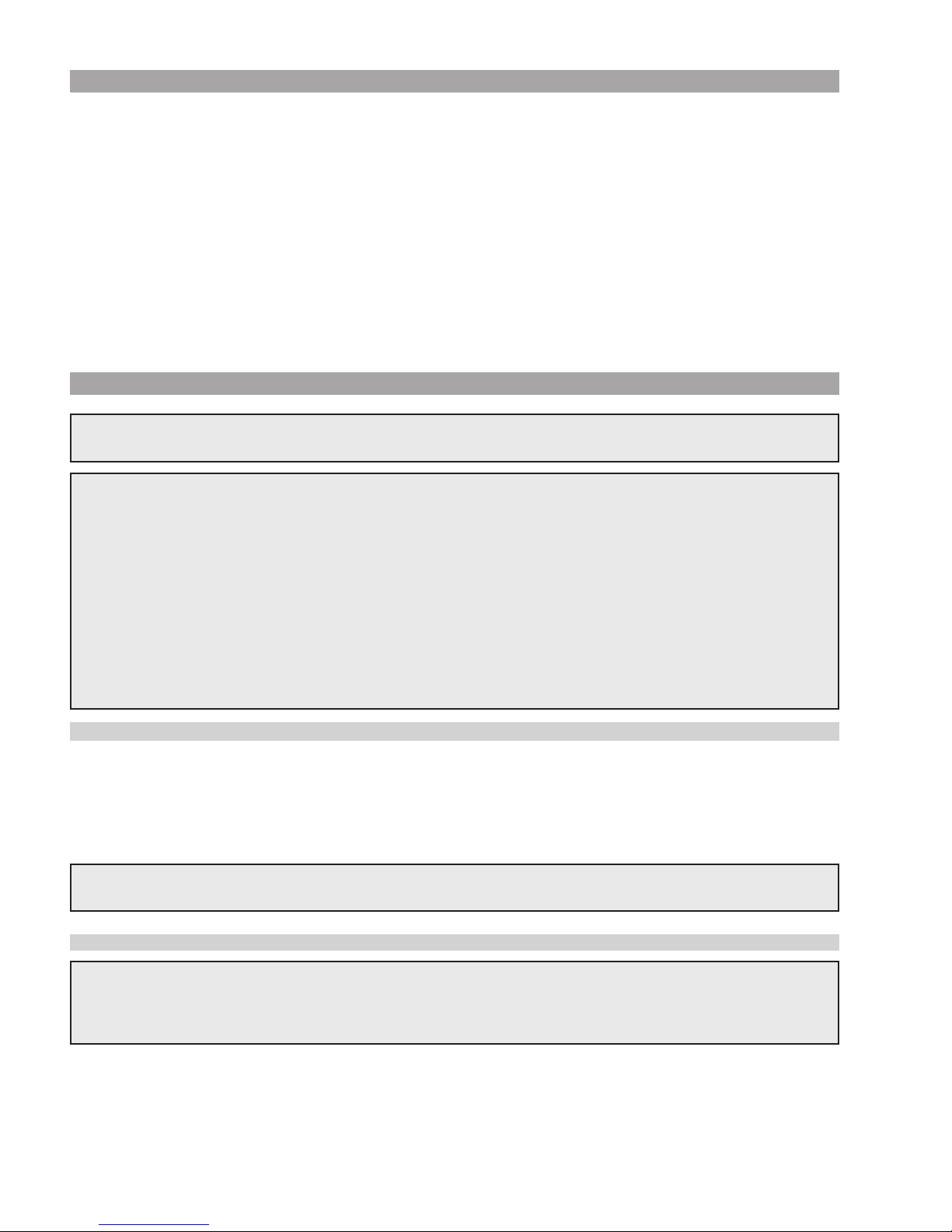
Heaters must not be installed under an overhang of less than five 5’ (1.52 m) from the top of the heater, and the
4’ (1.22 m)
Minimum
4’ (1.22 m)
Minimum
3’ (0.91 m)
Minimum
10’ (3.05 m)
Minimum
1’ (0.3 m)
Minimum
4’ (1.22 m)
Minimum
vent terminal must be a minimum of 5’ (1.52 m) from any overhang. See Page 18 for vent terminal location
requirements. Three sides must be open in the area under the overhang. Roof water drainage must be diverted away from the heaters installed under overhangs with the use of gutters.
For U.S. installations, the point from where the flue products exit the heater must be a minimum of 4’ (1.22 m)
below, 4’ (1.22 m) horizontally from, or 1’ (0.3 m) above any door, window or gravity inlet into any building. The
vent discharge of the heater shall be at least 3’ (0.91 m) above any forced air inlet, or intake ducts located within 10’ (3.05 m) horizontally.
For installations in Canada, pool heaters shall not be installed with the top of the vent assembly within 10’
(3.05 m) below, or to either side, of any opening into the building. Refer to the latest revisions of CAN/CSAB149.
For installations in Florida and Texas that must comply with the Florida or Texas Building Code, follow the
directions on page 13 for the installation of hurricane tie-down method for all models.
Fig. 2: Clearances
12
Page 13
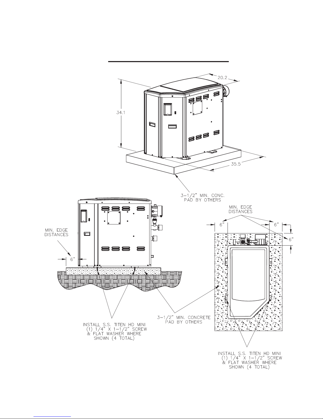
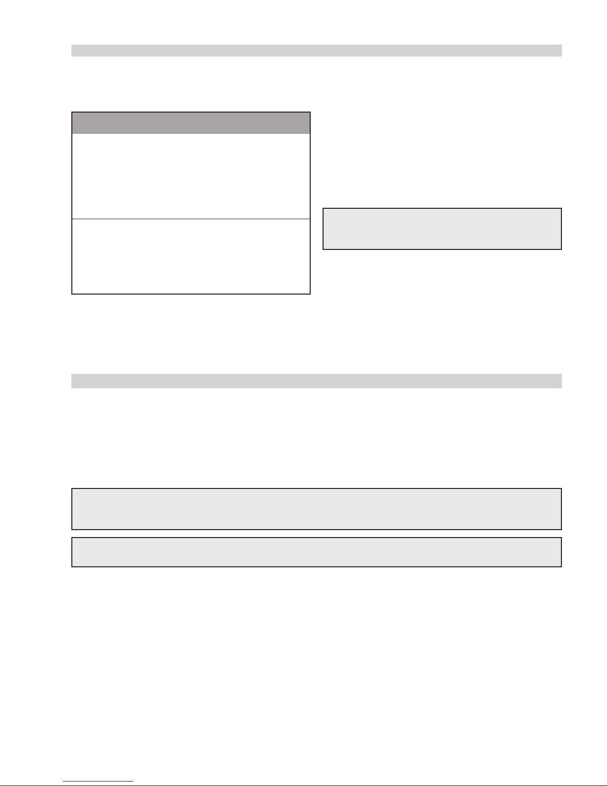
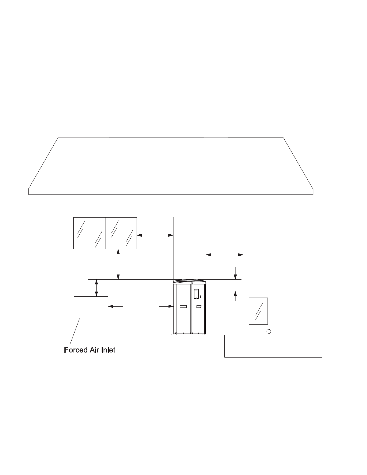
FLORIDA BUILDING CODE 2010
ULTIMATE WIND SPEED = 170 MPH, 3 SECOND GUST
NOMINAL WIND SPEED = 132 MPH
EXPOSURE = C
Gas Heater Model No. 410
Fig. 3: Hurricane Tie Down Instructions
13
Page 14

INDOOR HEATER INSTALLATION
The heater must always be vented to the outside. See the Venting section (beginning on page 17) for details.
Minimum allowable space is shown on the nameplate.
SPECIFICATIONS AND DIMENSIONS
Electrical Requirements:
120V/1ph/60Hz 5A
*Dimensions are in inches and [millimeters]
Fig. 4: Specifications and Dimensions
Dimensions
Heater
Model
SR-410 399.0 4” 4”
Notes:
1. The model number prefix indicates: (S=Stainless Steel Heat Exchanger), (R=Raypak) Model number suffix indicates: pilot type (E = Digital) and fuel type (P = Propane, N = Natural Gas). Example: Model number
SR-410-EN indicates a unit with digital (IID) ignition using natural gas with a stainless steel heat exchanger.
2. Heaters are rated for natural gas and propane up to 4,500 feet (1,371.6 m). For elevations over 4,500’
(1,371.6 m), consult the factory.
3. Flue gases must be properly vented with CAT III for horizontal and CAT IV for vertical venting. Inlet air can
be ducted with 4” (101.6 mm) metal or PVC pipe. See the venting section of this manual for complete venting details.
MBTU
Input
Flue
Diameter
(B)
Table 1: Specifications and Dimensions
Air Inlet
(C)
Minimum
Flow
40 GPM
(151 LPM)
Maximum
(473 LPM)
Flow
125 GPM
Shipping
Weight
300 (136 kg)
14
Page 15
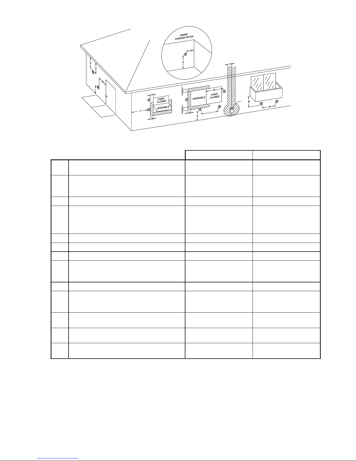
U.S. Installations
1
Canadian Installations
2
A
Clearance above grade, veranda, porch,
deck, or balcony
1 ft (30 cm) 1 ft (30 cm)
B
Clearance to window or door that may be
opened
4 ft (1.2m) below or to side
of opening; 1 foot (30 cm)
above opening
3 ft (91 cm)
C Clearance to permanently closed window * *
D
Vertical clearance to ventilated soffit located
above the terminal within a horizontal distance of 2 ft (61cm) from the centerline of the
terminal
5 ft (1.5m) *
E Clearance to unventilated soffit * *
F Clearance to outside corner * *
G Clearance to inside corner 6 ft (1.83m) *
H
Clearance to each side of center line extended above meter/regulator assembly
*
I Clearance to service regulator vent outlet * 3 ft (91cm)
J
Clearance to non-mechanical air supply inlet
to building or the combustion air inlet to any
other appliance
4 ft (1.2m) below or to side
of opening; 1 ft (30 cm)
above opening
3 ft (91 cm)
K Clearance to mechanical air supply inlet
3 ft (91 cm) above if within
10 ft (3m) horizontally
6 ft (1.83m)
L
Clearance above paved sidewalk or paved
driveway located on public property
7 ft (2.13m) 7 ft (2.13m) t
M
Clearance under veranda, porch, deck or
balcony
* 12 in. (30 cm) TT
1
In accordance with the current ANSI Z223.1/NFPA 54 National Fuel Gas Code
2
In accordance with the current CAN/CSA-B149 Installation Codes
t Vent terminal shall not terminate directly above sidewalk or paved driveway located between 2 single family dwellings that se rves
both dwellings
TT Permitted only if veranda, porch, deck, or balcony is fully open on a minimum of two sides beneath the floor and top of term inal and
underside of veranda, porch, deck or balcony is greater than 1 ft (30cm)
* Clearances in accordance with local installation codes and the requirements of the gas supplier
3 ft (91 cm) within a
height 15 ft above the
meter/regulator assembly
Fig. 5: Minimum Clearances from Vent/Air Inlet Terminations – Indoor and Outdoor Installations
Table 2: Vent/Air Inlet Termination Clearances
15
Page 16
COMBUSTION AND VENTILATION AIR (Indoor Units Only)
The heater must have both combustion and ventilation air. Minimum requirements for net free air supply openings are one opening that is 12” (304.8 mm) from the ceiling for ventilation, and one opening that is 12”
(304.8 mm) from the floor for combustion air as outlined in the latest edition of the National Fuel Gas Code, ANSI
Z223.1(Canada-CAN/CSA-B149) and any local codes that may have jurisdiction.
A. All Air From Inside The Building:
Each opening shall have a minimum net free area as noted:
Model Square Inches
SR-410 399 (0.26 m2)
B. All Air From Outdoors:
When air is supplied directly from outside the building, each opening shall have a minimum net free area
as noted:
Model
Unrestricted Opening (sq. in.)
Typical Screened or
Louvered Opening (sq. in.)
Typical Screened and
Louvered Opening (sq. in.)
SR-410 100 (0.06 m2) 150 (0.1 m2) 200 (0.13 m2)
CAUTION: Combustion air must not be contaminated by corrosive chemical fumes which can damage the
heater and void the warranty.
Table 3: Combustion Air Requirements
Direct Vent and Ducted Combustion Air Systems
If outside air is drawn through the intake pipe directly to the unit for combustion:
1. Install combustion air direct vent as instructed on page 22 (horizontal) or page 23 (vertical) of this manual.
2. Provide adequate ventilation of the space occupied by the heater(s) by an opening(s) for ventilation air at
the highest practical point communicating with the outdoors.
2
a) In the US, the total cross-sectional area shall be at least 1 in.
per kW) of total input rating of all equipment in the room when the opening is communicating directly
with the outdoors or through vertical duct(s). The total cross-sectional area shall be at least 1 in.
2
area per 10,000 BTUH (222 mm
per kW) of total input rating of all equipment in the room when the
opening is communicating with the outdoors through horizontal duct(s).
b) In Canada, there shall be permanent air supply opening(s) having a total cross-sectional area of not less
2
than 1 in.
of free area per 30,000 BTUH (70 mm2per kW) of the total rated input. The location of the
opening(s) shall not interfere with the intended purpose of the opening(s) for the ventilation air.
of free area per 20,000 BTUH (111 mm
2
of free
2
3. In cold climates, and to mitigate potential freeze-up, Raypak highly recommends the installation of a motor-
ized sealed damper to prevent the circulation of cold air through the heater during the non-operating hours.
16
Page 17

VENTING
CAUTION: Proper installation of flue venting is
critical for the safe and efficient operation of the
heater.
General
Appliance Categories
Heaters are divided into four categories based on the
pressure produced in the exhaust and the likelihood of
condensate production in the vent.
Category I – A heater which operates with a non-positive vent static pressure and with a vent gas temperature that avoids excessive condensate production in
the vent.
Category II – A heater which operates with a non-positive vent static pressure and with a vent gas temperature that may cause excessive condensate production
in the vent.
Category III – A heater which operates with a positive
vent pressure and with a vent gas temperature that
avoids excessive condensate production in the vent.
Category IV – A heater which operates with a positive
vent pressure and with a vent gas temperature that
may cause excessive condensate production in the
vent.
See the table below for appliance category requirements.
NOTE: For additional information on appliance
categorization, see appropriate ANSI Z21 Standard
and the NFGC (U.S.), or B149 (Canada), or
applicable provisions of local building codes.
WARNING: Contact the manufacturer of the vent
material if there is any question about the appliance
categorization and suitability of a vent material for
application on a Category III or IV vent system.
Using improper venting materials can result in
personal injury, death or property damage.
Combustion
Air Supply
From Inside Building
From Outside Building
(Direct Vent or
Ducted Combustion Air)
Exhaust
Configuration
Vertical
Venting
Horizontal
Through-the-Wall
Venting
Vertical Venting
with Ducted
Combustion Air
Vertical
Direct Vent
Horizontal
Direct Vent
Table 4: Venting Category Requirements
Heater
Venting
Category
IV
IV
IV
IV
IV
Certified Materials
(Must be UL 1738
or ULC S636)
Metallic Vent
(such as AL29-4C),
Duravent PolyPro,
ASTM D1785 Sch 40
PVC, ASTM F441
Sch 40 CPVC
Combustion Air
Inlet Materials
Galvanized Steel
PVC
ABS
CPVC
17
Page 18

Support of Vent Stack
The weight of the vent stack or chimney must not rest
on the heater vent connection. Support must be provided in compliance with applicable codes. The vent
should also be installed to maintain proper clearances
from combustible materials. Use insulated vent pipe
spacers where the vent passes through combustible
roofs and walls.
Vent Terminal Location
NOTE: During winter months check the vent cap
and make sure no blockage occurs from build-up of
snow or ice.
1. Condensate can freeze on the vent cap. Frozen
condensate on the vent cap can result in a blocked
flue condition.
damaging exterior finishes. Use a rust-resistant
sheet metal backing plate against brick or masonry surfaces.
12. DO NOT extend exposed vent pipe outside of
building beyond the minimum distance required
for the vent termination. Condensate could freeze
and block the vent pipe.
U.S. Installations
Refer to the latest edition of the National Fuel Gas
Code.
Vent termination requirements are as follows:
1. Vent must terminate at least 4’ (1.22 m) below, 4’
(1.22 m) horizontally from or 1’ (0.3 m) above any
door, window or gravity air inlet to the building.
2. Give special attention to the location of the vent
termination to avoid possibility of property damage or personal injury.
3. Gases may form a white vapor plume in winter.
The plume could obstruct a window view if the termination is installed near windows.
4. Prevailing winds, in combination with below-freezing temperatures, can cause freezing of condensate and water/ice build-up on buildings, plants or
roofs.
5. The bottom of the vent terminal and the air intake
shall be located at least 12” (304.8 mm). above
grade, including normal snow line.
6. Un-insulated single-wall metal vent pipe shall not
be used outdoors in cold climates for venting gasfired equipment.
7. Through-the-wall vents for Category IV appliances
shall not terminate over public walkways or over
an area where condensate or vapor could create a
nuisance or hazard or could be detrimental to the
operation of regulators, relief valves, or other
equipment.
8. Locate and guard vent termination to prevent accidental contact by people or pets.
9. DO NOT terminate vent in window well, stairwell,
alcove, courtyard or other recessed area.
2. The vent must not be less than 7’ (2.13 m) above
grade when located adjacent to public walkways.
3. Terminate vent at least 3’ (0.91 m) above any
forced air inlet located within 10’ (3.05 m).
4. Vent must terminate at least 4’ (1.22 m) horizontally, and in no case above or below unless 4’
(1.22 m) horizontal distance is maintained, from
electric meters, gas meters, regulators, and relief
equipment.
5. Terminate vent at least 6’ (1.8 m) away from adjacent walls.
6. DO NOT terminate vent closer than 5’ (1.52 m)
below roof overhang.
7. The vent terminal requires a 12” (304.8 mm) vent
terminal clearance from the wall.
8. Terminate vent at least 1’ (0.3 m) above grade,
including normal snow line.
9. Multiple direct vent installations require a 4’
(1.22 m) clearance between the ends of vent caps
located on the same horizontal plane.
WARNING: The Commonwealth of Massachusetts
requires that sidewall vented heaters, installed in
every dwelling, building or structure used in whole or
in part for residential purposes, be installed using
special provisions as outlined on page 50 of this
manual.
10. DO NOT terminate above any door, window, or
gravity air intake. Condensate can freeze, causing
ice formations.
11. Locate or guard vent to prevent condensate from
Canadian Installations
Refer to latest edition of the B149 Installation code.
18
Page 19

A vent shall not terminate:
1. Directly above a paved sidewalk or driveway
which is located between two single-family dwellings and serves both dwellings.
2. Less than 7’ (2.13 m) above a paved sidewalk or
paved driveway located on public property.
3. Within 6’ (1.8 m) of a mechanical air supply inlet to
any building.
4. Above a meter/regulator assembly within 3’
(0.91 m) horizontally of the vertical center-line of
the regulator.
5. Within 3’ (0.91 m) of any gas service regulator
vent outlet.
6. Less than 1’ (0.3 m) above grade level.
7. Within the 3’ (0.91 m) of a window or door which
can be opened in any building, any non-mechanical air supply inlet to any building or the combustion air inlet of any other appliance.
8. Underneath a verandah, porch or deck, unless the
verandah, porch or deck is fully open on a minimum of two sides beneath the floor, and the distance between the top of the vent termination and
the underside of the verandah, porch or deck is
greater than 1’ (0.3 m).
Venting Installation Tips
Support piping:
Condensate Management
The condensate must be drained properly to protect
the appliance and drainage system. The condensate
from the boiler is acidic. Its pH is between 3.2 and 4.5.
Raypak recommends neutralizing the condensate with
a Condensate Neutralizer kit (Z-12). The neutralizer kit
is connected to the drain system and contains limestone (calcium carbonate) chips to neutralize the pH
level of the condensate. The kit may be added to avoid
long-term damage to the drainage system and to meet
local code requirements.
Vent pipe condensate drains are also required for
installation of the X94 Professional. Follow vent manufacturer instructions for location of condensate drains
in the vent. The vent condensate should also be routed through a neutralization kit, as required by local
code requirements.
The neutralizer kit must be sized to the condensate
generated by the appliance and the vent.
CAUTION: In general, the condensate piping from
the appliance must have a downward slope of 1⁄4”
per horizontal foot. Condensate drain traps must be
primed with water to prevent gas flue leaks.
Neutralizers should be checked at least once per
year, and the chips should be replenished as necessary. When replacing the chips, they should be no
smaller than 3⁄4” to avoid blockage in the
condensate piping. Fig. 6 (on page 20) is a visual
guide only. Follow the man- ufacturer’s instructions
for the installation of the neutralization kit and
condensate drains.
• horizontal runs—at least every 5’ (1.52 m)
• vertical runs—use braces
• under or near elbows
WARNING: Examine the venting system at least
once a year. Check all joints and vent pipe
connections for tightness, corrosion or deterioration.
19
Page 20

Fig. 6: Vertical Venting
Venting Configurations
For heaters connected to gas vents or chimneys, vent
installations shall be in accordance with the NFGC
(U.S.), or B149 (Canada), or applicable provisions of
local building codes.
Vertical Venting (Category IV)
Installation
CAUTION: A listed vent cap terminal adequately
sized, must be used to evacuate the flue products
from the building.
NOTE: If installing multiple heaters with common
vent, contact the factory.
CAUTION: This venting system requires the
installation of a condensate drain in the vent piping
per the vent manufacturer’s instructions. Failure to
install a condensate drain in the venting system will
void all warranties on this heater. Condensate is
acidic and highly corrosive.
Fig. 7: Vertical Venting
NOTE: Ensure adequate clearances to allow annual
inspection of the venting system.
20
Page 21

The maximum and minimum venting length for this Category IV appliance shall be determined per the NFGC
(U.S.) or B149 (Canada).
Vent Length
Model
No.
Certified Vent
Material (UL 1738
or ULC-S636)
Vent and
Intake Air
Size
Min.
Max.
Stainless Steel, AL29-
4C,
ANSI/ASTM D1785
410
Sch 40 PVC,
ANSI/ASTM F441
4”
5’
(1.52 m)
65’
(19.81 m)
Sch 40 CPVC,
DuraVent
Polypropylene**
Table 5: Category IV Vent Requirements
* Subtract 10’ (3.05 m) per elbow. Max. 4 elbows.
** Only Duravent polypropylene is approved for the X94 Professional.
The connection from the appliance vent to the stack
must be as direct as possible and shall be the same
diameter as the vent outlet. The horizontal breaching
of a vent must have an upward slope of not less than
should have a minimum clearance of 4’ (1.22 m) horizontally from and in no case above or below (unless a
4’ (1.22 m) horzontal distance is maintained) electric
meters, gas meters, regulators and relief equipment.
1/4” (6.35 mm) per linear foot from the heater to the
vent terminal. The horizontal portions of the vent shall
also be supported for the design and weight of the
material employed to maintain clearances and to prevent physical damage or separation of joints.
The distance of the vent terminal from adjacent public
walkways, adjacent buildings, open windows and
building openings must be consistent with the NFGC
(U.S.) or B149 (Canada). Vents supported only by
flashing and extending above the roof more than 5 ft
NOTE: A vent adapter (field-supplied) may be
required to connect the Category IV vent to the
should be securely guyed or braced to withstand snow
and wind loads.
heater. The supplied vent adapter allows for direct
connection to DuraVent PolyPro, Duravent FasN
Seal, Sch 40 PVC and Sch 40 CPVC.
NOTE: When using PVC Tee vent as termination,
insert the round stainless mesh screens provided
Termination
with the unit into the tee ends.
Combustion
Air Intake
Pipe Material
Galvanized
Steel, PVC, ABS,
CPVC
Intake Air
Max. Length*
65’
(19.81 m)
The vent terminal should be vertical and should terminate outside the building at least 3’ (0.91 m) above the
highest point where it passes through the roof and 2’
(0.61 m) above the highest point of the roof or building
that is within 10‘ (3.05 m) horizontally. The vent cap
Model
No.
Size Approved Intakes
PVC 90° Elbow, Sch 40
410 4”
Galvanized 90° Elbow,
SS 90° Elbow, ABS 90° Elbow
Table 6: Horizontal Vent and Air Intake Terminals
*Must be ULC-S636 materials in Canada.
Approved Plastic
Terminals
4" PVC/CPVC Tee Sch
40* FasNSeal FSTT4
21
Approved SS
Terminals
Page 22

Horizontal Through-the-Wall Venting
(Category IV)
Model
No.
410 4” 65’ (19.81 m)
* Subtract 10’ (3.05 m) per elbow, maximum 4 elbows
The vent must be installed to prevent flue gas leakage.
Care must be taken during assembly to ensure that all
joints are sealed properly and are airtight. The vent
must be installed to prevent the potential accumulation
of condensate in the vent pipes. It is recommended
that the vent be insulated. Insulation is required for
installations in cold environments (i.e. below 40°F or
4°C). It is required that:
1. The vent must be installed with a condensate
drain located in proximity to the heater as directed
by the vent manufacturer.
Vent Size
Table 7: Max. Horizontal Vent Lengths
Maximum Horizontal
Vent Length*
Fig. 8: Horizontal Through-the-Wall Venting
CAUTION: This venting system requires the
installation of a condensate drain in the vent piping
per the vent manufacturer’s instructions. Failure to
install a condensate drain in the venting system will
void all warranties on this heater.
Installation
These installations utilize the heater-mounted blower
to vent the combustion products to the outdoors.
Combustion air is taken from inside the room and the
vent is installed horizontally through the wall to the outdoors. Adequate combustion and ventilation air must
be supplied to the equipment room in accordance with
the NFGC (U.S.) or B149 (Canada).
The total length of the horizontal through-the-wall flue
system should not exceed 65 equivalent ft (19.81 m) in
length. If horizontal run exceeds 65 equivalent ft
(19.81 m), an appropriately sized variable-speed
extractor must be used. Each elbow used is equal to
10’ (3.05 m) of straight pipe. This will allow installation
in one of the five following arrangements:
2. The vent must be installed with a slight upward
slope of not less than 1/4” (6.35 mm) per foot of
horizon-tal run to the vent terminal.
Termination
The direct vent cap MUST be mounted on the exterior
of the building. The direct vent cap cannot be installed
in a well or below grade. The direct vent cap must be
installed at least 1’ (0.3 m) above ground level and
above normal snow levels. A Raypak-approved vent
cap must be used. The vent terminal must be located
NO CLOSER than 12” (0.3 m) off the wall.
WARNING: No substitutions of flue pipe or vent
cap material are allowed. Such substitutions would
jeopardize the safety and health of inhabitants.
• 65’ (19.81 m) of straight flue pipe
• 55’ (16.76 m) of straight flue pipe and one elbow
• 45’ (13.72 m) of straight flue pipe and two elbows
• 35’ (10.67 m) of straight pipe and three elbows
• 25’ (7.62 m) of straight pipe and four elbows
The vent cap is not considered in the overall length of
the venting system.
22
Page 23

Direct Vent - Horizontal Throughthe-Wall
condensate trap must be installed per applicable
codes.
Installation
These installations utilize the heater-mounted blower
to draw combustion air from outdoors and vent combustion products to the outdoors.
Fig. 9: Horizontal Through-the-Wall Direct Venting
2. The intake vent must be insulated through the
length of the horizontal run.
Termination
The flue direct vent cap MUST be mounted on the exterior of the building. The direct vent cap cannot be
installed in a well or below grade. The direct vent cap
must be installed at least 1’ (0.3 m) above ground level
and above normal snow levels.
The direct vent cap MUST NOT be installed with any
combustion air inlet directly above a direct vent cap.
This vertical spacing would allow the flue products
from the direct vent cap to be pulled into the combustion air intake installed above.
This type of installation can cause non-warrantable
problems with components and poor operation of the
heater due to the recirculation of flue products. Multiple direct vent caps should be installed in the same
horizontal plane with a 4’ (1.22 m) clearance from the
side of one vent cap to the side of the adjacent vent
cap(s).
The total length of the through-the-wall flue and air
intake cannot exceed 65' (19.81 m) equivalent ft each
(130' (39.62 m) combined) in length. Each elbow used
is equal to 10’ (3.05 m) of straight pipe. This will allow
installation in one of the five following arrangements:
• 65’ (19.81 m) of straight flue pipe
• 55’ (16.76 m) of straight flue pipe and one elbow
• 45’ (13.72 m) of straight flue pipe and two elbows
• 35’ (10.67 m) of straight pipe and three elbows
• 25’ (7.62 m) of straight pipe and four elbows
The flue direct vent cap and air intake elbow are not
considered in the overall length of the venting system.
Care must be taken during assembly that all joints are
sealed properly and are airtight.
The vent must be installed to prevent the potential accumulation of condensate in the vent pipes. It is recommended that the vent be insulated. Insulation is
required for installations in cold environments (i.e.
below 40°F or 4°C).
For installations in extremely cold climate, it is required that:
1. The vent must be installed with a slight upward
slope of not more than 1/4” (6.35 mm) per foot of
horizontal run to the vent terminal. An approved
Combustion air supplied from outdoors must be free of
particulate and chemical contaminants. To avoid a
blocked flue condition, keep the vent cap clear of
snow, ice, leaves, debris, etc.
WARNING: No substitutions of flue pipe or vent
cap material are allowed. Such substitutions would
jeopardize the safety and health of inhabitants.
CAUTION: Condensate is acidic and highly
corrosive.
The direct vent termination cap MUST be furnished by
the heater manufacturer in accordance with its listing
(sales order option D-11).
Use only the special gas vent pipes listed for use with
Category IV gas burning heaters, such as the AL29-4C
stainless steel vents offered by M&G DuraVent (800835-4429), Selkirk Inc. (1-800-992-VENT or 1-800992-8368 in the US, or 1-888-SEL-KIRK or 1-888-7355475 in Canada), Protech System, Inc. (800-766-
3473), Z-Flex (800-654-5600) or American Metal
Products (800-423-4270). Additionally, M&G DuraVent
PolyPro special gas vent and, where allowed, PVC
and CPVC Sch 40 pipe with appropriate listings may
be used. Pipe joints must be positively sealed. Follow
the vent manufacturer’s installation instructions carefully.
23
Page 24

Fig. 10: Outdoor Venting
Fig. 11: 3 in 1 Multi-Vent Adapter
24
Page 25

Direct Vent—Vertical
with the NFGC (U.S.) or B149 (Canada).
Installation
These installations utilize the heater-mounted blower
to draw combustion air from outdoors and force the
heated flue products through the vent pipe under positive pressure. The vent material must be in accordance with the above instructions for vent materials.
Vent material must be listed by a nationally recognized
test agency.
The connection from the appliance flue to the stack
must be as direct as possible and should be the same
size or larger than the vent outlet.
It is recommended that the intake vent be insulated in
colder climates.
Termination
The flue terminal should be vertical and should terminate outside the building at least 2’ (0.61 m) above the
highest point of the roof within 10’ (3.05 m). The vent
cap should have a minimum clearance of 4’ (1.22 m)
horizontally from and in no case above or below
(unless a 4’ (1.22 m) horizontal distance is maintained)
WARNING: No substitutions of vent pipe or vent
cap material are allowed. Such substitutions would
jeopardize the safety and health of inhabitants.
Vent pipes supported only by flashing and extended
above the roof more than 5’ (1.52 m) should be
securely guyed or braced to withstand snow and wind
loads.
The air inlet opening MUST be installed 1’ (0.3 m)
above the roof line or above normal snow levels that
might ob-struct combustion air flow. This dimension is
critical to the correct operation of the heater and venting system and reduces the chance of blockage from
snow. The vent cap must have a minimum 3’ (0.91 m)
vertical clearance from the air inlet opening.
Use only the special gas vent pipes listed for use with
Category IV gas burning heaters, such as the AL29-4C
stainless steel vents offered by Selkirk Inc. (1-800992-VENT or 1-800-992-8368 in the US, or 1-888SEL-KIRK or 1-888-735-5475 in Canada), Protech
System, Inc. (800-766-3473), Z-Flex (800-654-5600)
or American Metal Products (800-423-4270). Pipe
joints must be positively sealed. Follow the vent manufacturer’s installation instructions carefully.
Outdoor Installation
A 5" (127 mm) length of 4" (101.6 mm) schedule 40
PVC pipe and a 4" (101.6 mm) schedule 40 PVC Tee
are provided for typical outdoor installations. If needed additional vent (up to 65’ (19.81 m) equivalent) may
be added to locate the vent discharge away from the
appliance. When additional venting is supplied, the
vent must be supported and traps installed. In cold climates, it may be necessary to insulate the additional
venting..
Fig. 12: Direct Vent - Vertical
electric meters, gas meters, regulators and relief
equipment. The distance of the vent terminal from
adjacent public walkways, adjacent buildings, open
windows and building openings must be consistent
Care must be taken when locating the heater outdoors, because the flue gases discharged from the
vent cap can condense as they leave the cap.
Improper location can result in damage to adjacent
structures or building finish. For maximum efficiency
and safety, the precautions on page 25 must be
observed:
1. Periodically check venting system. The heater’s
venting areas must never be obstructed in any
way and minimum clearances must be observed
NOTE: Remove the unused gaskets from the 3 in 1
appliance vent adapter. For example, when using
the supplied PVC vent pipe remove the inner two
gaskets. See Figure 10.
NOTE: Condensate can freeze on the vent cap.
Frozen condensate on the vent cap can result in a
blocked flue condition.
25
Page 26

GAS SUPPLY CONNECTIONS
GAS PRESSURE ADJUSTMENT LOCATIONS
Fig. 14: Gas Valve
Fig. 13: Gas Supply Connections
Gas piping must have a sediment trap ahead of the
heater gas controls, and a manual shut-off valve located outside the heater jacket. All gas piping should be
tested after installation in accordance with local codes.
CAUTION: The heater and its manual shut-off valve
must be disconnected from the gas supply during any
pressure testing of that system at test pressures in
excess of 1/2 psi (3.45 kPa). Dissipate test pressure
in the gas supply line before reconnecting the heater
and its manual shut off valve to gas supply line. FAILURE TO FOLLOW THIS PROCEDURE MAY DAMAGE THE GAS VALVE. OVER PRESSURIZED GAS
VALVES ARE NOT COVERED BY WARRANTY. The
heater and its gas connections shall be leak tested
before placing the appliance in operation. Use soapy
water for leak test. DO NOT use open flame.
NOTE: Do not use Teflon tape on gas line pipe
thread. A pipe compound rated for use with natural
and propane gases is recommended. Apply sparingly only on male pipe ends, leaving the two end
threads bare.
SUPPLY PRESSURES
A minimum of 4” WC (1 kPa) and a maximum of
10.5“ WC (2.62 kPa) upstream pressure under load
and no-load conditions must be provided for natural
gas. A minimum of 12“ WC (3 kPa) and a maximum of
14“ WC (3.5 kPa) are required for propane gas under
load and no-load conditions, with no more than a 30%
pressure drop between static pressure and full load.
The factory manifold pressure settings should
be -2.0”± 0.5” WC (0.5 ± 0.12 kPa) at high fire (7500
+/- 50 RPM fan speed) for either natural or propane
gas.
PIPE SIZING FOR GAS CONNECTIONS
Maximum Equivalent Pipe Length (ft)
Natural Gas 1000 BTU/FT
0.60 Specific Gravity @ 0.5 in. WC Pressure Drop
Propane Gas 2500 BTU/FT
1.53 Specific Gravity @ 0.5 in. WC Pressure Drop
Input 3/4” 1” 1-1/4” 1-1/2”
Model (KBTU) N P N P N P N P
15 20 55 95 225 215 480
410 399.0 *
*A 3/4” gas line can be used for up to 5’ (1.52 m) maximum length
from the gas valve in addition to the sediment trap.
** Dimension in meters.
4.6**6.1**16.8**29**68.6**65.5**146
3
3
**
Table 8: Pipe Lengths for Gas Connections
HEAT EXCHANGER PRESSURE DROP TABLES
Heat Exchanger with External Automatic Bypass
WATER FLOW
(GPM)
40 (151.4 LPM) 5.3 (1.32 kPa)
50 (189.3 LPM) 5.9 (1.47 kPa)
60 (227.1 LPM) 6.2 (1.54 kPa)
70 (265 LPM) 7.2 (1.79 kPa)
80 (302.8 LPM) 8.6 (2.14 kPa)
90 (340.7 LPM) 9.7 (2.42 kPa)
100 (378.5 LPM) 11.3 (2.81 kPa)
110 (416.4 LPM) 13.2 (3.29 kPa)
120 (454.2 LPM) 15.3 (3.81 kPa)
125 (473.2 LPM) 16.5 (4.11 kPa)
HEAD LOSS
(FT WC)
Table 9: Heat Exchanger Pressure Drop
26
Page 27

FLOW RATES
From Heater To Heater
From
Pool/Spa
To
Pool/Spa
AUXILIARY BYPASS VALVE
(DO NOT USE GATE VALVE)
AUXILIARY BYPASS VALVE ADJUSTMENT
MODEL PIPE SIZE MIN. GPM MAX. GPM*
410 1-1/4”–1-1/2” - 2”
*When flow rates exceed maximum GPM an external auxiliary
bypass valve is required. See external auxiliary bypass valve section for details.
40
(151.4 LPM)
125
(473.2 LPM)
Table 10: Flow Rates
EXTERNAL AUTOMATIC BYPASS VALVE
An external automatic bypass valve is provided with
the heater. The bypass valve automatically responds
to changes in water flow in the piping system. The
proper amount of water flow is maintained through the
heater under varying system flows dictated by the conditions of the pump and filter.
To set bypass: With clean filter, adjustment is made by
feeling the inlet and outlet pipes at the heater. Outlet
pipes should be slightly warmer than inlet and comfortable to the touch. If pipe is hot, close bypass; if cold,
open bypass.
PRESSURE RELIEF VALVE PIPING
The heater is supplied with a pressure relief valve,
sized for the maximum output of the heater, and set at
125 psig. The pressure relief valve outlet must be
plumbed to a safe point of discharge.
Fig. 15: External Automatic Bypass Valve
EXTERNAL AUXILIARY BYPASS VALVE
(Where Required)
An auxiliary bypass valve should be used when flow
rates exceed 125 GPM (473.2 LPM). Usually a highperformance pump larger than two horsepower will
exceed this flow rate. This valve is required to complement the function of the automatic bypass valve, particularly when starting the heater in winter or early
spring when the spa or pool temperature is below 50°F
(10ºC). It also serves to eliminate needless pressure
drop through the heater and accompanying reduction
in the flow rate to the spa jets, etc.
Fig. 17: PRV Piping
NOTE: To avoid water damage or scalding due to
valve operation, drain pipe must be connected to
valve outlet and run to a safe place of discharge.
Drain pipe must be the same size as the valve discharge connection throughout its entire length and
must pitch downward from the valve. No shut-off
valve shall be installed between the relief valve and
the drain line. Valve lever should be tripped at
least once a year to ensure that waterways are
clear.
Fig. 16: Auxiliary Bypass Valve
27
Page 28

120V HEATER
SUPPLY
SIDE
RETURN
or
NEUTRAL
HEATER
6 WIRES
L1
HOT
RED
BLACK BLACK
BLACK
GREEN GREEN
WHITE WHITE
WHITE
ELECTRICAL WIRING
TRANSFORMER WIRING
NOTE: If it is necessary to replace any of the original wiring, use 105°C wire or its equivalent, and/or
150°C wire or its equivalent, like the original wiring.
WARNING: Heaters are factory-wired for a 120
VAC, 60 Hz, single phase power supply. DO NOT
attempt to operate with any other power supply.
CAUTION: Heater must be electrically grounded
and bonded. Bonding lug is provided loose with the
heater. Install bonding lug on lower right or left side
of jacket as necessary for bonding the heater.
Mounting hole is provided on the jacket.
NOTE: Failure to ground the heater electrically
could affect the heater’s electronics.
The Electronic Intermittent Ignition Device automatically lights the main burner upon a call for heat.
NOTE: See page 42 for further instructions if using
a time clock/fireman’s switch.
120 VAC WIRING
The heater requires 5 amps of 120V/1ph/60Hz power.
To wire the 120V power supply to the heater, connect
the pair of black wires to the “L1” or hot leg of the
power supply. Connect the pair of white wires to the
“Ret” or neutral leg of the power supply. Attach the wire
nut to the red wire. There should be no connection
to the red wire for 120 VAC operation.
The heater must be electrically grounded and bonded
in accordance with local codes, or, in the absence of
local codes, with the latest edition of the National
Electrical Code, ANSI/NFPA 70. (Canada - Canadian
Electrical Code, CSA C22.1, Part 1 and Part 2.)
WARNING: The transformer’s primary side is
wired for 120 VAC and if 240 VAC is applied, damage to the transformer and PC board may result.
Such damages are not covered under manufacturer’s limited warranty.
NOTE: Input power to the heater (120 VAC) can
be supplied from the load (pump) side of time clock
or directly from the GFCI power source. It is
required that full-time power be supplied to the
heater from the GFCI power source, and that
the heater be controlled by the fireman’s switch
connection or using a two or three-wire remote.
See pages 40-42. If using a switched GFCI power
source, the heater post-purge function will be
bypassed, adversely affecting heater operation and
life.
Fig. 18: Wiring Locations
Fig. 19: 120 VAC Wiring
28
Page 29

PLUMBING—WATER CONNECTIONS
The heater has standard right-hand plumbing connections, but can be converted to alternate configurations as
shown below.
STANDARD RIGHT-HAND CONNECTIONS LEFT-HAND CONNECTIONS
LEFT-IN / RIGHT-OUT CONNECTIONS RIGHT-IN / LEFT-OUT CONNECTIONS
Fig. 20: Water Connection Configurations
LOOSE PLUMBING PARTS SETUP
The loose parts bag contains the pieces needed to
connect your plumbing to the heater, see page 9 for
list. Two options are recommended for the installer as
shown in the following images.
NOTE: Use appropriate CPVC or CPVC to PVC
transition primer and glue for attachments.
29
Page 30

Fig. 21: Plumbing Setup
RECOMMENDED PLUMBING SETUPS
The heater requires water flow and positive pressure to fire and operate properly. It must therefore be installed
downstream of the discharge side of the filter pump. A typical installation is plumbed as follows:
1. The inlet side of the filter is plumbed directly to the discharge side of the filter pump;
2. The outlet side of the filter is then plumbed to the inlet of the heater; and
3. The outlet of the heater is plumbed to the return line to the pool or spa. The pump, filter and heater are thus
plumbed in series (Salt generators and chemical feeders must be down stream of the pool heater).
Plumbing from the heater back to the pool or spa must not have any valves or restriction that could prevent flow
when the pump is operating.
CAUTION: An additional source of heated water, e.g. a solar system, must be connected to the main line
ahead of the heater inlet pipe in order for it to act as the primary heat source. If the primary system provides
adequate heat to maintain set-point, the heater will not fire. Be advised that the control panel will then display
sensed water temperatures downstream of the primary heating system, rather than the temperature of the
water exiting the pool.
Heater must be located so that any water leaks will not damage the structure of adjacent area. PVC pipe may
be glued directly into the bypass connections.
Fig. 22: Single Pool or Spa
Heater Installation
30
Page 31

Fig. 23: Multiple Pool or Spa
Heaters Installation
Fig. 24: Single Pool/Spa
Heater Installation
Fig. 25: Multiple Pool/Spa
Heaters Installation
31
Page 32

WIRING DIAGRAM
Fig. 26: Wiring Diagram
32
Page 33

SECTION 4 - SERVICING INSTRUCTIONS
GENERAL LOCATION OF CONTROLS
Fig. 27: Location of Controls
33
Page 34

CONTROL ADJUSTMENTS
Fig. 28: Control Adjustments
CONTROL PANEL REMOVAL
To remove the PC board from the heater, use the following procedure:
1. Turn off main power to the heater.
2. Remove front door to access wire harnesses.
3. Reaching underneath the PC board, carefully remove all connectors and wires from the PC board and
ON/OFF toggle switch.
4. Lift the front bezel lid and remove the two lower Phillips screws.
5. Carefully lift the control panel upwards and pull away from the heater.
6. The control panel can now be flipped around to remove or inspect the PC board.
7. Reverse procedure for re-installation.
Fig. 29: Control Panel Removal
34
Page 35

THERMOSTAT OPERATION - DIRECT SPARK (DS) BOARD
Program
Button
(SW1)
Controls Operation
The pool heater touchpad, located on the upper portion of the angled corner panel of the heater, allows the
user to select the mode of operation, adjust the setpoint temperature, configure the heater controls and
access diagnostic information. The LCD display window indicates the mode (OFF, SPA, POOL, MANUAL,
SCHEDULE A/B), the water temperature and if applicable the heater setpoint and current operating condition. A manual power switch provided turns the control
power ON or OFF.
Mode Selection
The MODE button is used to select POOL, SPA, MANUAL OVERRIDE or RUN SCHEDULE operation. It
also allows the user to turn the heater off electronically by selecting the OFF mode, allowing the LCD display to remain energized and to continue showing the
actual water temperature.
POOL and SPA Modes
If the heater is in POOL or SPA mode, the mode, day
of week and time are displayed on the top line of the
display. The current water temperature, desired water
temperature (SETPOINT), and current status are
shown alternating on the lower line of the display. The
temperature SETPOINT can be adjusted using the UP
or DOWN buttons.
In POOL and SPA modes, the heater will operate to
maintain the desired water setpoint temperature, turning the heater on when the temperature falls below the
setpoint and turning the heater off when setpoint temperature is reached. Filter pump, motorized valve,
auxiliary outputs and heating operation will operate
according to INSTALLER SETUP MODE settings (See
page 36).
MANUAL OVERRIDE
MANUAL OVERRIDE mode allows manual operation
of controller functions for up to 24 hours. The user
may select filter pump speed, activate or deactivate
heating, select valve positions (if used) and turn auxiliary relays on (if used) for the desired override time
period.
RUN SCHEDULE A/B
RUN SCHEDULE A/B modes will operate the heater
and all controlled features according to a user defined
7 day schedule. The schedules are programmed by
pressing and holding the MODE button for 5 seconds
while in RUN SCHEDULE mode. Schedules A and B
may each be set with up to 4 different operating periods per day, individually for each day of the week, or
for the same schedule every day. While operating in
RUN SCHEDULE mode, pressing the UP or DOWN
buttons will toggle between schedules A and B.
Service Menu and Fault History
To access the Service Menu and Fault History, press
the MODE and UP buttons simultaneously for 3 to 5
seconds. The heater will continue to operate normally while in the Service Menu. While in the Service
Menu use the UP and DOWN buttons to make
changes (where available) and the MODE button to
enter changes and/or move to the next item.
Fault History - Use the UP and DOWN buttons to view
the last 10 fault codes recorded. See page 38 & 39 for
a description of the faults.
Clear Faults – Faults may be cleared by selecting YES
and pressing MODE.
Run Hours/Cycles (view only) – The Run Hours indicates the total hours of operation for the pool heater,
as measured by the amount of time that the main gas
valve has been powered. The Cycle count indicates
the number of on/off cycles of the heater, as measured
by the number of times the main valve has been powered.
Voltage (view only) – Displays the incoming control
voltage. Normal readings range from 24 to 29 Volts.
Water (view only) – Displays the current sensed water
temperature at the inlet of the heater. Note: This temperature will not be an accurate representation of the
pool or spa temperature unless the filter pump is running.
Flame Strength (view only) – Indicates flame signal
strength when the heater is firing. A signal of less than
4 indicates a weak flame signal and may require
35
Page 36

service.
Fan RPM (view only) - Indicates Fan RPM target
(lower left) and actual (lower right) speeds.
INSTALLER SETUP MODE
The Installer Setup Mode is accessed by pressing and
holding the program button (SW1) on the back of the
temperature/ignition control board (see page 35) for 5
seconds. SW1 can be accessed by either removing
the top of the heater or by removing the door panel
where the control is mounted (the wiring includes a
service loop to allow the panel to be removed providing access to the board without removing the wiring).
In Installer Setup Mode the UP and DOWN buttons are
used to modify items and the MODE button is used to
move between menu items and to store changes. If no
button is pressed for 60 seconds the control will exit
Installer Setup Mode and any value change of the current item will not be saved in memory.
Eco mode offers increased efficiency and reduced
operating sound levels by reducing the operating fan
speed by 30%. Turbo mode operates to provide maximum heat input for the shortest heat up times.
Spa Fan Mode - Eco – Efficiency, Turbo – Rapid
Heat or Comfort Modulate Selection
Use the UP and DOWN buttons to select Eco –
Efficiency, Turbo – Rapid Heat or Comfort - Modulate
mode of operation. Eco mode offers increased efficiency and reduced operating sound levels by reducing the operating fan speed and gas input rate by 30%.
Turbo mode operates to provide maximum heat input
for the shortest heat up times. Comfort mode offers
fast heat up, operating at maximum input until the spa
return water temperature approaches setpoint. Once
within 1.5ºF (0.8ºC) of setpoint the heater begins to
modulate the input rate to match the required heating
load. Comfort mode provides a steady stream of heated water to the spa, reducing heater on/off cycles.
Set Current Time
Use the UP and DOWN buttons to set the current time.
Press MODE to save and move on to the next item.
Set Current Day
Use the UP and DOWN buttons to set the current day
of the week. Press MODE to save and move on to the
next item.
C/F Display – Celsius or Fahrenheit temperature
scale selection
Use the UP or DOWN buttons to select Fahrenheit or
Celsius for the temperature display. Choose the
desired temperature scale and press MODE to save
and move on to the next item.
Spa Max Temp – Spa Set Point Maximum
Adjustment
Use the UP and DOWN buttons to change the maximum spa temperature setting to your desired value.
The control can be set for a maximum of 107°F
(41.6ºC). Press MODE to save and move on to the
next item.
Pool Max Temp – Pool Set Point Maximum
Adjustment
Use the UP and DOWN buttons to change the maximum pool temperature setting to your desired value.
The control can be set for a maximum of 104°F
(41.6ºC). Press MODE to save and move on to the
next item.
Pool Fan Mode – Eco – Efficiency or Turbo – Rapid
Heat Selection
Use the UP and DOWN buttons to select Eco –
Efficiency or Turbo – Rapid Heat mode of operation.
Flue Monitor – Flue Temperature Monitoring
Use the UP and Down buttons to select between PVC,
CPVC/PP or OFF for the flue temperature monitor.
Select PVC when using PVC vent materials. For
CPVC, polypropylene or stainless steel vent materials
use the CPVC/PP setting. While it is not recommended, the flue monitor may be turned off when using
stainless steel vent. The Flue Monitor utilizes a temperature sensor in the stack and will reduce the firing
rate of the heater when the vent temperature
approaches the limits of PVC or CPVC/polypropylene
vent materials.
Max Fan RPM
Use the UP and Down buttons to adjust the maximum
fan speed. Max Fan RPM may be adjusted from 70007500 RPM. It may be beneficial to reduce the Max
Fan RPM at high altitude, for installations with long
intake air ducting or to reduce sound levels. Reducing
the fan RPM from 7500 to 7000 RPM will reduce the
maximum input of the heater by 6 to 7%.
Pump Operation – Configure the Pump Control
Use the UP and Down buttons to select between
Disabled, 1 Speed, 2 Speed, 4 Speed and Variable
pump controls. Select Disabled if the heater controls
will not be used to control the pump.
• 1 Speed – The control will close and open the
Pump Relay activating the pump contactor to turn
the pump on and off.
• 2 Speed – The control will close and open the
Pump Relay to turn the pump on and off and trigger Low speed operation. The Aux 2 Relay will
close to enable High speed.
• 4 Speed - The control will close and open the
Pump Relay to turn the pump on and off (or to
36
Page 37

enable and disable a pump with full time power).
The control will also power one of the Variable
Pump outputs to select the pump speed. Pin 5 will
enable Speed 1, Pin 4 Speed 2 , Pin 3 Speed 3
and Pin 2 Speed 4.
• Variable - The control will close and open the
Pump Relay to turn the pump on and off (or to
enable and disable a pump with full time power).
Variable Pump output Pin 2 will provide a signal to
directly control the speed of a pulse width modulation (‘PWM’) pump motor.
Return Valve (Selection available only with Valve
Operation enabled)
Use the UP and DOWN buttons to define the valve
positions for the Return Valve. Valve Position 1 can be
set to Pool or Spa.
Suction Valve (Selection available only with Valve
Operation enabled)
Use the UP and DOWN buttons to define the valve
positions for the Suction Valve. Valve Position 1 can
be set to Pool or Spa.
Spa Heat Speed (Selection available only with
Pump Operation enabled and 2, 4 or Variable
speed pump)
Use the UP and DOWN buttons to select between the
available options. Available options will be based on
the Pump Operation selected in the previous step.
Spa Heat Speed must be set to provide a minimum of
40 gpm to the heater.
Pool Heat Speed (Selection available only with
Pump Operation enabled and 2, 4 or Variable
speed pump)
Use the UP and DOWN buttons to select between the
available options. Available options will be based on
the Pump Operation previously selected. Pool Heat
Speed must be set to provide a minimum of 40 gpm to
the heater.
Filter Speed (Selection available only with Pump
Operation enabled and 2, 4 or Variable speed)
Use the UP and DOWN buttons to select between the
available options. Available options will be based on
the Pump Operation previously selected. Filter speed
should be set to provide the required turns for proper
sanitation, calculated based on the estimated Filter
Speed flow rate, body of water volume and the scheduled pump on time.
Freeze Protect (Selection available only with Pump
Operation enabled)
Use the UP and DOWN buttons to enable or disable
freeze protection. When Freeze Protect is enabled the
control will monitor water temperature when in Remote
and Run Schedule modes. If the water temperature
sensor on the heater measures a temperature below
40ºF (4.4ºC) the control will activate the pump for 15
minutes. After 15 minutes the pump will shut off once
the water temperature exceeds 42ºF (5.5ºC).
Valve Operation (Selection available only with
Pump Operation enabled)
Use the UP and DOWN buttons to enable or disable
operation of motorized three-way valves.
Valve Chng Delay (Selection available only with
Valve Operation enabled)
Use the UP and DOWN buttons to enable or disable
the Valve Change Delay function. When enabled, the
pump will be turned off for 30 seconds before the
valves will begin to change positions. After 30 seconds for the valves to rotate (1 minute total off time)
the pump will be re-started. If the water flow switch is
closed (indicating water flow is present) when the control is attempting to change valve positions, “WPS
Closed” will be indicated on the LCD, and the control
will wait for the water flow switch to open before
resuming operation.
Aux 1
Use the UP and DOWN buttons to select between
OFF, Ext Heat, Remote Out and Aux Output.
• OFF – The Aux 1 relay is not used.
• Ext Heat – The Aux 1 Relay activates an external
heat source when the thermostat has a call for
heat. The external heat source operates as the
first stage of heating with the master heater acting
as the second stage, activating the second stage
when the water temperature is 2ºF (1.1ºC) or more
below setpoint.
• Remote Out - The Aux 1 relay will provide a parallel output to a remote device such as an external
heat source when the thermostat has a call for
heat. The master heater will operate according to
thermostat demand with the Aux 1 relay closing 10
seconds after the master heater has started heating. The Aux 1 remote output will cease when the
heat demand is satisfied.
• Aux Output - The Aux 1 relay will close and open
according to the Run Schedule program or Manual
Override commands.
Aux 2
Aux 2 provides a second relay output with the same
options as Aux 1. Note that with 2-speed pumps Aux
2 will not be available as it is used to enable high pump
speed.
37
Page 38

Low Temp Lockout
Use the UP and DOWN buttons to enable or disable
the low water temperature lockout function. Low Temp
Lockout will inhibit the pool heater from firing if water
temperature is sensed below 36ºF (2.2ºC). The X94 is
designed to operate with low inlet water temperatures
under start up conditions, but it is not intended to maintain temperatures below 50ºF (10ºC) or operate with
water temperatures below 36ºF (2.2ºC). Disabling the
Low Temp Lockout is not recommended as operation
with water temperatures below 36ºF (2.2ºC) will
adversely affect heater life.
EcoNet Address
Use the UP and DOWN buttons to select the EcoNet
Address, 1 to 16, for the heater when there are multiple pool heaters on an EcoNet network.
“Lockout Cleared.” Failure to enter the correct PIN will
display “Invalid PIN.”
In the event that the user-selected PIN is lost or does
not clear the Control Lockout, use the Program Button
to access the Installer Setup Mode to Set Factory
Defaults. This will clear the PIN and allow normal
operation and selection of a new PIN if desired. See
the Installer Setup Mode directions on page 36 for
details.
NOTE: Set Factory Defaults will reset all Installer
Setup Mode items, temperature settings and schedules to factory defaults. Prior to resetting, verify that
all current data is recorded on the Control Settings
form on page 51 of the manual prior to using the Set
Factory Defaults function.
Set Factory Defaults
Use the UP and Down buttons to select Yes or No.
Selecting Yes will return all installer and schedule settings to factory defaults.
Control Lockout
The heater is equipped with a Control Lockout feature
to prevent unauthorized tampering or adjustment of
the control settings. To lock out the controls, press the
DOWN button and MODE button for 5 seconds.
Choose a three digit PIN, using the UP and DOWN
buttons to select the digits and the MODE button to
lock in selections. Confirm your selection and record
your PIN.
To unlock the controls, press any button to bring up the
Enter PIN menu. Enter the PIN that was used to lock
the control. Note that power cycling will not clear the
lockout. Successfully unlocking the control will display
Display Condition
WPS Stuck Closed
Valves not operated because the water flow switch is closed and Valve Chng Delay is
enabled
NOTE: The LCD temperature display may not
agree with the temperature reading of your pool or
spa thermometer. The heater reads the water temperature at the inlet to the heater. Due to the circulation characteristics of any pool or spa, the water temperature at the inlet to the heater may differ from that
observed at a given location in the pool or spa.
STATUS AND DIAGNOSTICS
The digital thermostat models are programmed to display a variety of status and diagnostic messages,
depending on the operating conditions.
The following heat status and error condition messages are displayed in Pool, Spa, and Remote modes.
The heat status messages are displayed only if there
are no active fault conditions.
Water Sw Open
Valve Chng Delay Pump/Heat shut off because of valve switching
High Heating Second stage heat is running with EXT HEAT Aux mode
Heating Heater is operating
Spark Ignition control is running spark
Post Purge Ignition control is in the post-purge period
Pre-Purge Ignition control is in pre-purge or inter-purge
External Heat External device is running 1st stage instead of Gas Ignition (EXT HEAT Aux mode)
No Demand Heat demand is satisfied
Heat not running because the water flow switch is open
38
Page 39

Display Condition
H2O Sensor Fail Water temperature sensors open, shorted, or disagree
Aux Ctrl Fault 2 ROM CRC failure on companion board
Aux Ctrl Fault 3 RAM failure on companion board
Aux Ctrl Fault 5 A/D Reference failure on companion board
Aux Ctrl Fault 6 A/D Multiplexor failure on companion board
Aux Ctrl Fault 8 Unable to read time of day clock
Ign Ctrl Fault 2 ROM CRC failure on Ignition Control
Ign Ctrl Fault 3 RAM failure on Ignition Control
Ign Ctrl Fault 5 A/D failure on Ignition Control
Ign Ctrl Fault 6 Flame sense circuit failure on Ignition Control
Ign Ctrl Fault 7 Out of sequence execution detected on Ignition Control
Hi Water Temp Water temperature exceeded 108F
Remote Error Both Spa and Pool inputs are energized
Hi Limit 1 Fault High Limit 1 is open
Hi Limit 2 Fault High Limit 2 is open
Blocked Vent Vent/Field switch #1 is open
Vent Temp Limit Vent Temp Limit switch is open
Clock/Fireman Sw Clock/Fireman switch is open (Not stored in EEPROM)
Air Flow Sw Open Air Pressure Switch open with inducer on
Air Flow Sw Closed Air Pressure Switch closed with inducer off
5 Min Ind Off Inducer off for 5 minutes because the inducer’s interlock didn't close
Fan Lockout 3 fan switch faults within same heat demand cycle
Ignition Failure No flame detected within 4 seconds (Natural gas only, not stored in EEPROM)
Ign 60 min Delay Ignition trial failed 3 times in single call for heat (Natural Gas only, not stored in EEPROM)
Ignition Lockout Ignition trial failed on Propane
MV Output Fault Ignition control has detected problem with gas valve output
Flame w/o CFH Ignition Control is sensing flame present with gas valve closed
Low Temp Lockout Ignition Control has shut down heat because water temp < 36F
EEPROM Fault Corrupted data found on the Companion board
Ign EEPROM Fault Corrupted data found on the Ignition Control
Low Voltage Displayed when supply voltage < 20, no operational changes
Flue Over Temp Heater shut off because flue temperature is too high
Flue Sense Fail Flue Monitor is enabled and Flue temperature sensor is open or shorted
Blocked Drain Condensate drain switch is closed
Fan RPM Fault FAN RPM more than 500 RPM different than target
Table 11: Error Condition Messages
39
Page 40

REMOTE CONTROL INSTALLATION AND OPERATION
CAUTION: Before installing remote controls to the heaters, read the following:
The digital thermostat model is remote-ready in most cases. The digital liquid crystal display (LCD) shows the
actual pool temperature, operating status, and service codes (See examples below). The touch pad on the control panel allows you to select the desired pool or spa temperature. It also indicates when a remote system is
controlling the heater by displaying Remote in the display. When connecting the heater to a remote system,
identify whether it is a two- or three-wire remote system. Select the appropriate instruction listed below to properly install the remote to the heater.
OFF Mode
7-PIN Remote
Interface Harness
Heating in the POOL Mode
Pool Common
(BLK/ORN)
Spa Common
(ORN/BLK)
24VAC HOT
(BLU)
REMOTE OPERATION
The heaters are equipped with the ability to work with
external remote controls. The supplied 7-pin remote
wiring connector supplies power out to either a toggle
switch or the switch contacts of a third party remote.
The remote works by either making or breaking the circuit created by the remote wiring. Typically, a remote
does not supply power to the heater, it only provides a
switching function to turn the heater On or Off. If your
remote is supplying its own voltage to the heater,
it will not work with this heater and may damage
the digital circuit board.
Heating in the SPA Mode
Remote Mode
ACTIVATING THE REMOTE
To activate or deactivate the remote function, follow
these steps:
Press and hold the UP and DOWN arrow buttons for
3 to 5 seconds.
The second line of the display will alternate even
when the unit is off (“No Demand”).
For operation of the heater using the onboard thermostatic controls with a time clock, see the “Time Clock /
Fireman’s Switch” section on page 42.
NOTE: When in remote operation, the keypad
mode and temp buttons are disabled.
Note: Electrostatic Discharge (ESD) damage can be caused by
direct or indirect contact with the wiring or circuit board. When
one walks to the heater area, an electrostatic charge accumulates on the body. Contact of a finger allows the body to discharge, possibly causing device damage. This damage can be
limited if the service person discharges himself, following ESD
preventive/removal practices, and holds on to the heater enclosure for 5 seconds before proceeding.
40
Page 41

REMOTE CONTROL WIRING
P8 Connector
ORN/BLK - To Spa (COMM)
Wire Nut - BLK/ORN
To Pool (COMM)
BLU - 24VAC
P8 Connector
ORN/BLK - To Spa (COMM)
BLK/ORN - To Pool (COMM)
BLU - 24VAC
Important Installation Notes for Remote or External Wiring Configuration
• Remote wiring must be run in a separate conduit.
• Remote wiring must not be run parallel to high voltage lines.
• For runs of under 30 feet (9.1 m), remote wiring should have stranded conductors with a minimum of 22
AWG, 600V, cable twisting 1.5 to 2.5 inch (38.1 to 63.5 mm) lay and jacketed.
• For runs over 30 feet (9.1 m), the conductors should be a minimum of 20 AWG, 600V, cable twisting 1.5”
(38.1 mm) to 2.5” (63.5 mm) to lay that is shielded and jacketed.
• Maximum cable length is 200 feet (60.9 m).
• For both two- and three-wire remote systems, the provided 7-pin wiring connector must be utilized. Please
refer to the wiring instructions.
NOTE: The remote wires must be connected to the 7-pin connector
before
the connector is plugged into the board.
2-Wire Remote Control (On-Off)
This application assumes that only one heating function (pool or spa) is required.
1. Turn on power to the heater.
2. For a 2-Wire Remote Control from a remote without
its own sensor, push the mode button to the “POOL” or
“SPA” mode and set the desired setpoint (eg. 102 °F (39ºC) for Spa).
3. For a 2-Wire Remote Control from a remote with
its own sensor, push the mode button “POOL” or “SPA”
mode and set the temperature to the highest setting available on the control. The actual setpoint will be controlled by the remote control.
4. Press the mode button to "OFF" and remove power from the heater.
5. On the "Remote Interface Harness", connect the BLUE wire to one side of the "REMOTE" switch and connect the other side to either the ORANGE/BLACK wire for "SPA" operation or the BLACK/ORANGE wire for
"POOL" operation.
6. Attach wire nut on unused wire to the "Remote Interface Harness."
7. Install the "7-Pin Remote Interface Harness" to the P8 connector and turn power “ON” to the heater.
To activate the remote control, see page 40.
3-Wire Remote Control Using Three-Position Switch (Pool-Off-Spa, or Low-Off-High)
This application assumes that both heating functions (pool and spa) are required.
1. Turn on power to the heater.
2. Push the mode button to the "POOL" or "SPA" mode and set the desired temperature for each (eg. 80°F
(27ºC) for Pool and 102°F (39ºC) for Spa).
3. Press the mode button to "OFF" and remove power from the heater.
4. On the "Remote Interface Harness" connect the BLUE wire to one side of the "REMOTE" switch and con-
nect the ORANGE/BLACK wire for "SPA" operation and the BLACK/ORANGE wire for the "POOL" operation.
5. Install the "Remote Interface Harness" to the P8 connector and turn power "ON" to the heater.
To activate the remote control, see page 40.
2-Wire Remote Control 3-Wire Remote Control
41
Page 42

TIME CLOCK/FIREMAN’S SWITCH
To operate the heater with a time clock, connect the
timer to the fireman’s switch connection in the heater’s
wiring. The time clock should be of the dual switch
type and set to shut off the call for heat to the pool
heater 15 to 20 minutes prior to shutting down the pool
pump. The fireman’s switch connection is located on
the 6-pin header connected to the digital control board.
Splice into the red wire jumper tagged “Where necessary add “Fireman’s” switch circuit here” to connect the
time clock. The fireman’s switch connection must
be a dry contact and must not supply power to the
heater. Powering the fireman’s switch connection
externally may damage the heater, and is not
cov-
ered by warranty.
Do not exceed 50’ (15.24 m) of total wiring using 18
AWG stranded copper wire rated for 105ºC (221ºF)
minimum.
NOTE: When using a time clock, the heater will
display “Clock/ Fireman Sw” when the fireman’s
switch is open, indicating that the time clock has
shut off the call for heat.
Fig. 31: Flow Switch
BLOCKED VENT SWITCH
This heater is equipped with a blocked vent pressure
switch to prevent the operation of the heater when the
vent is blocked.
HIGH LIMITS
The heater is equipped with two automatic high limits.
Both are located in the inlet/outlet header. Both are set
to open at 135°F (57ºC).
NOTE: An erratic high limit is often characteristic
of an internal heat exchanger problem, e.g. scale
build-up, defective bypass. Refer to Troubleshooting
section (starting on page 44).
HIGH LIMIT REMOVAL
1. Shut off main electrical power switch to heater.
2. Remove front door.
3. Remove defective high limit and replace with a
new high limit.
4. Replace inspection panel.
Fig. 30: High Limit
Fig. 32: Blocked Vent Switch
ADJUSTING VALVE MANIFOLD PRESSURE
1. Gas manifold pressure is measured at the pressure tap between the gas valve and gas orifice
(See Fig. 32).
2. To increase the manifold pressure and increase
the ratio of fuel to air turn the adjustment screw
counterclockwise (toward the +) (See Fig. 31). For
example, a reading of -2.0" WC (-0.5 kPa) can be
increased to -1.5" WC (-0.4 kPa) by turning the
adjustment screw counterclockwise. Increasing
manifold pressure will increase the CO
percent-
2
age in the flue gases.
3. To decrease the manifold pressure and decrease
the ratio of fuel to air turn the adjustment screw
clockwise (toward the -) (See Fig. 31). Decreasing
manifold pressure will reduce the CO
percentage
2
in the flue gases.
NOTE: Manifold pressure will decrease when the
intake air filter becomes dirty. Replace the filter
when manifold pressure drops to less than -2.5" WC
or intake suction pressure is less than -1.0" WC.
FLOW SWITCH
This standard, dual-purpose control, mounted and
wired in series with the main gas valve, shuts off
heater in case of pump failure or low water flow.
42
Page 43

Fig. 33: Gas Valve
VISUAL INSPECTION
Flames can be observed through the sight glass next
to the igniter. A blue colored flame indicates normal
operation. At least every three months a visual inspection should be made.
COMBUSTION SETTINGS
Verify that the gas orifice matches the fuel type supplied. The natural brass finish orifice is for natural gas
and the black oxide finish orifice is for Propane. Table
11 shows the desired ranges for CO
% and limits for
2
CO ppm. Follow the instructions from the Adjusting
Valve Manifold Pressure section to make adjustments.
Desired CO
% and max CO ppm apply to all firing
2
rates, but firing rate must be stable for a good reading
(fan RPM should not change more than 50 RPM while
taking a sample).
Fuel Type
Natural Gas 8.6 – 9.2 100
Propane 9.5 – 10.1 100
CO2Range
(%)
CO Max
(PPM)
ELECTRICAL
Be sure that electrical service to the heater has proper overload fuse or circuit breaker protection, wire size
and connections which comply with all applicable
codes.
CAUTION: Prior to replacing any component,
make sure that the main gas, power, and pumps
are turned OFF.
ORIFICE REMOVAL
Fig. 34: Gas Train
The gas orifice is located on the gas train, between the
gas valve and the combustion blower.
1. Locate and close the external manual shut-off
valve.
2. Loosen the external gas union.
3. Locate and remove front door panel.
4. Locate and remove the (4) bolts & nuts holding the
gas orifice in place. See the figure above.
5. Carefully remove the gas orifice and do not misplace the o-rings attached to the flanges.
6. Inspect and/or replace the orifice with the correct
size.
Table 12: Combustion Settings
NOTE: Orifices for propane gas have a black oxide
finish.
IGNITER REMOVAL
Fig. 35: Igniter
1. Locate and remove the top panel.
2. Locate the igniter in front of the blower and burner.
3. Locate and disconnect the high tension spark
cable from the igniter.
4. Using a 5/16” (8 mm) socket, remove the (2) bolts
holding the igniter down.
5. Using a flat screw driver, loosen the igniter bracket from the combustion chamber, preferably on
both sides.
6. Carefully remove the igniter from its location. In
order to remove the igniter without damaging the
refractory, it is necessary to rotate the igniter 90
degrees clockwise before lifting it out of the heater.
7. When replacing or inspecting the igniter, the gap
between the ground & spark tips should be 0.15”±
0.01” (3.81± 0.25 mm). The gap between the
spark and ground rods should be uniform and the
rods should not be distorted. Inspect the ceramic
insulator at the base of the spark rod carefully for
cracks, replace the igniter if any defects are found.
43
Page 44

SECTION 5 - TROUBLESHOOTING
PROBLEM CAUSE SOLUTION
Harmonics, or whining noise *Debris or restriction in system..............
*Debris in gas line..................................
Low flow.................................................
Heater going on and off Dirty filter................................................
with Water SW Open
indication on LCD or in
Fault History
Low water level in pool..........................
External bypass setting out of
adjustment............................................
Valve opens but no flame Manifold pressure too low………………
visible
Flame visible for a split Ignition not being sensed………………..
second
Liming or scale forming in Pool water............................................
exchanger Bypassing too much water...................
Sooting Low water temperatures.........................
*Air starvation.........................................
*Improper venting...................................
*Insects or debris clogging
burner intake ports...............................
Yellow lazy flame Air intake clogged or incorrect
fan operation..........................................
*Insects or debris clogging
burner intake ports.................................
Outer jacket very hot *Broken refractory caused by
(paint blistered) shipping damage or improper
combustion..........................................
Excessive sooting of heat exchanger....
Hard lighting at startup Igniter faulty……………………………….
Takes too long to heat Under-sized heater...............................
pool or spa Htr. output(BTUH)
Pool gallonage x 8.33
Filter not running long enough.............
Dirty filter..............................................
Gas line or meter undersized...............
Leaking at T&P gauge Overacid...............................................
Leaking at heat exchanger Overacid...............................................
Gasket brittle and leaking (overheated)
Refractory damage..............................
Sooted heater.......................................
Combustion fan not running Fan relay...............................................
“Fan 5 min Delay”, Fan........................................................
“Fan Lockout” or "Fan RPM
Fault" indication
Burned motor .......................................
Motor control failure..............................
Heater turns on for less Wiring....................................................
than 4 seconds Incorrect supply wiring..........................
(no display error)
PC Board short.....................................
Ignition not sensed………………….…..
Clean igniter with wire brush.
Replace board if no strength signal is being detected.
Replace fan relay.
Loose connection or failed motor.
Incorrect wiring, replace blower.
Replace blower.
Check for loose or broken (verify continuity) wiring/ground/ignition wire.
Check incoming power for correct voltage. There should be
no power on the neutral line.
Check for debris upstream of fan intake. Check intake air filter suction
pressure, replace filter if dirty.
Clean burners with a gentle application of compressed air, do not use
a brush.
Air intake feedback to regulator
disconnected.......................................... Check that tubing between air intake adapter and regulator is connected
and free of obstruction. See Fig. 1.
This does not take into account heat loss due to weather.
Replace igniter
Reset time clock.
Clean filter.
Refer to installation instructions.
Replace T&P gauge and maintain proper water chemistry.
See Water Chemistry on page 2.
Inspect bypass for movement, if no movement, replace.
Maintain water body temperatures above 50ºF (10ºC).
Heating Capacity =
Locate the restriction and remove. Flush system and clean.
Remove debris or blow out gas line.
Scale forming in heat exchanger - clean heat exchanger and
check pool pH and total alkalinity.
Clean or replace filter.
Raise water level.
Determine cause of sooting & correct.
Calculate heating capacity of heater or refer to heater sizing chart.
Replace refractory panels.
Replace refractory.
Determine cause of sooting and correct.
Replace heat exchanger and maintain proper water chemistry.
Clean burners with a gentle application of compressed air, do not use
a brush.
Refer to installation instructions.
Follow recommended installation instructions.
Adjust bypass.
Increase manifold pressure (turn clockwise slightly).
Replace ignition wire. Check connections. Increase manifold pressure
(turn clockwise slightly).
MECHANICAL
IMPORTANT NOTICE These instructions are intended for the use of qualified personnel who are specifically trained and experienced in the
installation of this type of heating equipment and related system components. Installation and service personnel may be required by some
states to be licensed. Persons not qualified shall not attempt to install this equipment nor attempt repairs according to these instructions.
* Indicates symptom which usually occurs on initial start-up.
44
Page 45

Power On
Is the water
temperature displayed?
NO
YES
Push MODE
button to select
"Pool" or "Spa"
Push UP or DOWN
button to scroll to
desired temperature
NO
Water temperature
and set
temperature
displayed?
YES
“Purge”
NO
NO
YES
YES
Water temp displayed?
(rectified)
Heater Fired?
END
• Check On/Off switch (under lid on control panel)
• Check for 120 volts to the transformer
(time clock, circuit breaker, wire connections)
• Check for 24 volts to Circuit Board (P6 connector)
“Remote” and Water Temperature displayed
(a remote control is controlling the heater)
Note: Disconnect the remote by turning the
remote function off. (Press and hold the UP
and DOWN buttons for 5 seconds.)
NO
YES
Is a fault code displayed and flashing?
Diagnostic Readouts
“Sensor Failure,” “Sensor Open” or “Sensor Short” -
Temperature sensor out of range (replace sensor)
Verify power at MV on P-4 Terminal on digital circuit board.
Verify power to valve MV voltage. (Replace valve.)
“Spark”
Sensor Failure
Inspect thermistor, wires, and connector at Terminal P1
Check resistance value of the thermistor. Reference to chart below.
Replace thermistor if not within 10% of values shown below.
If okay, replace Circuit Board.
Temp Degrees F 40 50 60 70 80 90 100 106
Temp Degrees C 4.4 10 15.6 21.1 26.7 32.2 37.8 41.1
Resistance (k)
261.1 199.0 153.1 118.8 93.0 73.3 58.3 51.0
If okay, replace Circuit Board
Sensor resistance at various temperatures
“Water Sw Open” Water flow switch. Verify water flow and pressure. If water
connections were reversed, verify the location and direction
of the water flow across the flow switch.
CLEAN FILTER / STRAINER - backwash if neccessary.
“Hi Limit 1 Fault” High limit switch. Verify water flow. Inspect internal
“Hi Limit 2 Fault” bypass valve.
“Clock/Fireman Sw” Fireman or Remote switch connected to safety loop is in the
OFF mode.
“Blocked Vent” Vent switch open. Check connections to the board.
Check for blockages in the vent.
“EOL” (at start-up) Check for stuck MODE button.
“Ignition Lockout” Ignition lockout. Check spark (bad ignition circuit or
hi-tension wire).
“Ignition Failure” Ignition failure. Verify gas to the heater. Verify valve operation
(manifold pressure at tapping downstream of gas valve.)
CONTROL LOGIC - FLOW CHART (POOL AND SPA MODES)
45
Page 46

SECTION 6 - REPLACEMENT PARTS
46
Page 47

47
Page 48

NOTE: To supply you with the correct part, it is impor-
CALL
OUT DESCRIPTION 410
B BURNER
1-B Burner 015449F
2-B Gasket seal N/A
3-B Burner Mounting Plate N/A
4-B Burner Plenum Gasket 015450F
5-B Gas Orifice Natural (0-4,500 Ft)* 015452F
Gas Orifice Propane (0-4,500 Ft)* 015453F
6-B Gas Orifice Flange O Ring 014089F
CCONTROLS
1-C Thermostat Auto Reset 135 Deg 600892B
2-C P. C. Board/Ignition 014090F
3-C LCD Display 013640F
4-C Fuse 5 AMP 013733F
5-C Seal Gasket 014866F
6-C P. C. Board Digital Control 015454F
7-C Temperature Sensor Water/Flue 009577F
8-C Water Flow Switch 015115F
9-C Flow Switch Paddle 010026F
10-C Switch Air Pressure (Vent/Field) 010354F
11-C Rocker Switch 009493F
12-C Vent Temp Limit Switch 013428F
F FAN
1-F Blower 015455F
2-F Blower Gasket 015456F
3-F Co mb us ti on Ai r Ven tu ri Ad ap te r 015457F
4-F Hose Duct 4" (Plastic) 015519F
G GAS VALVE
1-G Combination Valve - Nat. 013942F
Combination Valve - Pro. 013942F
2-G Gas Valve Flange O Ring 014089F
3-G Manual "A" On/Off Valve 013208F
4-G Bleedle Valve 1/8 NPT 007423F
H HEAT EXCHANGER
1-H Heat Transfer 015458F
2-H Bypass Manifold 015459F
3-H Bypass Valve 006716F
4-H Bypass Spring 015460F
5-H Bypass Shaft 015461F
6-H Bypass Cap 015462F
7-H O Ring Bypass Cap 015463F
8-H Drain Valve 013475F
9-H CPVC Swivel Union & Nut (2) 015464F
10-H CPVC Adapter 015465F
11-H CPVC Nut N/A
12-H O Rin
g
Adapter 015466F
J CONTROL BOX
1-J Control Box N/A
2-J Transformer 120/240/24V 014404F
3-J Blower Relay DPDT 24V 011720F
4-J Pump Contactor 009860F
*FOR INSTALLATIONS OVER 4,500 FEET ABOVE SEA LEVEL, DERATE 4% PER I,000 FEET ABOVE
SEA LEVEL. CONSULT FACTORY.
tant that you supply the heater model number, serial
number and type of gas when applicable.
If determined defective by the Company and within
warranty, a like part or equal substitution will be
returned, freight collect. Credit will not be issued.
Any part returned for replacement under standard
MANUFACTURER:
company warranties must be properly tagged with a
return parts tag, completely filled in with the heater
serial number, model number, etc., and shipped to the
2151 EASTMAN AVENUE
OXNARD, CA 93030
Company freight prepaid.
48
Page 49

CALL
OUT DESCRIPTION 410
M MISCELLANEOUS COMPONENTS
1-M PRV 75 PSI 007223F
2-M T & P Gauge 014647F
3-M Wire Harnesses (All Unit Harnesses) 015467F
4-M Cabinet Harness 015468F
5-M Blower Harness 120V 015469F
6-M Gas Valve Harness 015470F
7-M High Limit / Flow Switch Harness 015471F
8-M Condensate Float Switch Harness 015472F
9-M Control Bezel (Includes Switch Decal) 014886F
10-M Switch/Decal-Membrane 014887F
11-M Control Bezel Cover 014888F
12-M Condensate Trap 015473F
13-M Condensate Float Switch NC 013947F
14-M Condensate Hose 013948F
15-M Condensate Neutralizer (Not Shown) 015199
16-M Insulation Blanket 015474F
17-M Window Combustion Chamber 006947F
18-M Touch-up Paint Cool Dark Gray (Not Shown) 750256
19-M RTV Sealant 2.8 oz. (Not Shown) 008924F
20-M Clear Silicone Sealant 10 oz (Not Shown) 015421F
21-M Plastic Handle 012681F
P PILOT
1-P Igniter Direct Spark 015475F
2-P Igniter Gasket 015476F
3-P Hi Tension Wire 014126F
R REFRACTORY
1-R Refractory (All Panels) 015477F
2-R Refractory Left & Right 015478F
3-R Refractory Front & Rear 015479F
4-R Refractory Top 015480F
S SHEET METAL / CABINET
1-S Jacket To p 015481F
2-S Upper Cabinet Supports 015482F
3-S Vertical Supports 015483F
4-S Heat Transfer Vertical Supports 015484F
5-S Vertical Cabinet Supports 015485F
6-S Flue Collector 015486F
7-S Flue Collector Seal Gasket 015487F
8-S Flue Collector Outlet Gasket 015488F
9-S Flue Exhaust Inlet Collar 015489F
10-S Flue Exhaust Inlet Gasket 015490F
11-S Flue Exhaust Outlet Support Bracket 015491F
12-S Access Panel Intake Air 015521F
13-S Access Panels Inlet/Outlet 015492F
14-S Jacket Control Mounting Panel 015493F
15-S Jacket Front Panel 015494F
16-S Jacket Rear Panel 015495F
17-S Jacket Side Panel Upper Right 015496F
18-S Jacket Side Panel Lower Right 015497F
19-S Jacket Side Panel Left 015498F
VVENTING
1-V Outdoor Vent Termination Tee
PVC Venting 015451
Polypropylene Venting N/A
Stainless Steel Venting 015361
2-V Flue Exhaust Polypropylene Pipe Assy 015507F
3-V Flue Exhaust Adapter 4" (PVC, Polyproplylene, or Stainless Steel) 015508F
4-V Intake Air Filter Box 015520F
5-V Air Filter Media 013290F
CONVERSION KITS* 410
Nat. to Pro. 015502F
Pro. to Nat. 015503F
* Gas conversions are to be done only by a qualified agency.
49
Page 50

Important Instructions for the Commonwealth of Massachusetts
The Commonwealth of Massachusetts requires compliance
with regulation 248 CMR 4.00 and 5.00 for installation of
through – the – wall vented gas appliances as follows:
(a) For all side wall horizontally vented gas fueled equipment
installed in every dwelling, building or structure used in
whole or in part for residential purposes, including those
owned or operated by the Commonwealth and where the
side wall exhaust vent termination is less than seven (7) feet
above finished grade in the area of the venting, including but
not limited to decks and porches, the following requirements
shall be satisfied:
1. INSTALLATION OF CARBON MONOXIDE DETECTORS.
At the time of installation of the side wall horizontal vented
gas fueled equipment, the installing plumber or gasfitter shall
observe that a hard wired carbon monoxide detector with an
alarm and battery back-up is installed on the floor level
where the gas equipment is to be installed. In addition, the
installing plumber or gasfitter shall observe that a battery
operated or hard wired carbon monoxide detector with an
alarm is installed on each additional level of the dwelling,
building or structure served by the side wall horizontal vented gas fueled equipment. It shall be the responsibility of the
property owner to secure the services of qualified licensed
professionals for the installation of hard wired carbon
monoxide detectors
a. In the event that the side wall horizontally vented gas
fueled equipment is installed in a crawl space or an attic, the
hard wired carbon monoxide detector with alarm and battery
back-up may be installed on the next adjacent floor level.
b. In the event that the requirements of this subdivision can
not be met at the time of completion of installation, the owner
shall have a period of thirty (30) days to comply with the
above requirements; provided, however, that during said
thirty (30) day period, a battery operated carbon monoxide
detector with an alarm shall be installed.
2. APPROVED CARBON MONOXIDE DETECTORS. Each
carbon monoxide detector as required in accordance with
the above provisions shall comply with NFPA 720 and be
ANSI/UL 2034 listed and IAS certified.
3. SIGNAGE. A metal or plastic identification plate shall be
permanently mounted to the exterior of the building at a minimum height of eight (8) feet above grade directly in line with
the exhaust vent terminal for the horizontally vented gas
fueled heating appliance or equipment. The sign shall read,
in print size no less than one-half (1/2) inch in size, "GAS
VENT DIRECTLY BELOW. KEEP CLEAR OF ALL
OBSTRUCTIONS".
(b) EXEMPTIONS: The following equipment is exempt from
248 CMR 5.08(2)(a)1 through 4:
1. The equipment listed in Chapter 10 entitled "Equipment
Not Required To Be Vented" in the most current edition of
NFPA 54 as adopted by the Board; and
2. Product Approved side wall horizontally vented gas fueled
equipment installed in a room or structure separate from the
dwelling, building or structure used in whole or in part for residential purposes.
(c) MANUFACTURER REQUIREMENTS - GAS EQUIPMENT VENTING SYSTEM PROVIDED. When the manufacturer of Product Approved side wall horizontally vented gas
equipment provides a venting system design or venting system components with the equipment, the instructions provided by the manufacturer for installation of the equipment and
the venting system shall include:
1. Detailed instructions for the installation of the venting system design or the venting system components; and
2. A complete parts list for the venting system design or venting system.
(d) MANUFACTURER REQUIREMENTS - GAS EQUIPMENT VENTING SYSTEM NOT PROVIDED. When the
manufacturer of a Product Approved side wall horizontally
vented gas fueled equipment does not provide the parts for
venting the flue gases, but identifies "special venting systems", the following requirements shall be satisfied by the
manufacturer:
1. The referenced "special venting system" instructions shall
be included with the appliance or equipment installation
instructions; and
2. The "special venting systems" shall be Product Approved
by the Board, and the instructions for that system shall
include a parts list and detailed installation instructions.
(e) A copy of all installation instructions for all Product
Approved side wall horizontally vented gas fueled equipment, all venting instructions, all parts lists for venting
instructions, and/or all venting design instructions shall
remain with the appliance or equipment at the completion of
the installation.
4. INSPECTION. The state or local gas inspector of the side
wall horizontally vented gas fueled equipment shall not
approve the installation unless, upon inspection, the inspector observes carbon monoxide detectors and signage
installed in accordance with the provisions of 248 CMR
5.08(2)(a)1 through 4.
50
Page 51

Installer Setup Record
Use this sheet to record Installer Setup Mode settings. This record will simplify setup in
the event it is necessary to Reset Factory Defaults or install a new control. It is also a helpful troubleshooting tool, allowing all setup parameters to be viewed on a single page.
Installer Setup Item
Celsius or Fahrenheit °C or °F Fahrenheit
Spa Max Temp 104°F
Pool Max Temp 104°F
Pool Fan Mode Eco / Turbo Turbo
Spa Fan Mode Eco / Turbo / Comfort Turbo
Flue Monitor PVC / CPVC/PP / OFF PVC
Max Fan RPM 7500 RPM
Pump Operation
Spa Heat Speed Disabled
Pool Heat Speed Disabled
Write down or circle the
Installer Setup setting
Disabled / 1 Speed / 2 Speed
/ 4 Speed / Variable
Default Setting
Disabled
Filter Speed Disabled
Freeze Protect Enabled (with Pump Operation)
Disabled (only available with
Valve Operation
Return Valve Position 1 = Pool (if enabled)
Suction Valve Position 1 = Pool (if enabled)
Valve Change Delay Disabled
Aux 1 OFF
Aux 2 OFF
Low Temperature Lockout Enabled
EcoNet Address 16
Control Lockout PIN
pump operation enabled)
51
Page 52

www.raypak.com
Raypak, Inc., 2151 Eastman Avenue, Oxnard, CA 93030 (805) 278-5300 Fax (805) 278-5468
Litho in U.S.A.
 Loading...