

Page 1
INSTALLATION INSTRUCTIONS
Flue
Exhaust
Tee
FFoorr HHii DDeellttaa
MMooddeellss 330022BB––22334422BB
FOR YOUR SAFETY: Do not store or use gasoline or other flammable vapors and liquids or other combustible materials in the vicinity of this or any other appliance. To
do so may result in an explosion or fire.
WHAT TO DO IF YOU SMELL GAS:
• Do not try to light any appliance.
• Do not touch any electrical switch; do not use any phone in your building.
• Immediately call your gas supplier from a neighbor's phone. Follow the gas supplier's instructions.
• If you cannot reach your gas supplier, call the fire department.
Installation and service must be performed by a qualified installer, service agency or
the gas supplier.
Catalog No. 1000.59B Effective: 06-24-10 Replaces: 08-04-08 P/N 241290 Rev. 3
Page 2
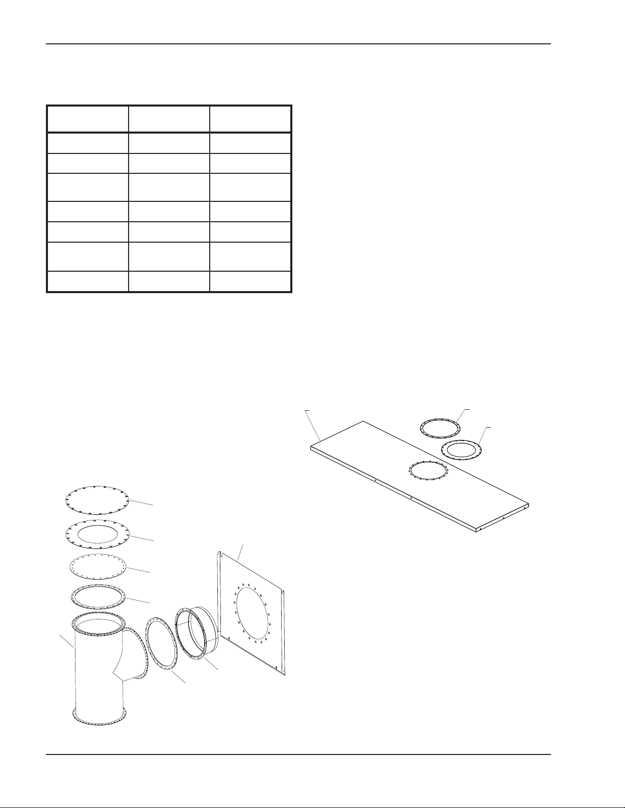
AVAILABLE KITS
Flue exhaust gasket
retainer
Flue exhaust adapter
seal gasket
Jacket top panel
G
F
D
C
A
C
B
E
INSTALLATION
Model
Vent
Diameter
Order Number
302B 5” 011838
402B-502B 6” 011839
652B, 752B,
902B
8” 011840
992B 10” 011841
1262B, 1532B 12” 011842
1802B, 2002B,
2072B
14” 011843
2342B 16” 011844
Kit Contents
Each kit includes:
• Flue exhaust tee (A)
• Flue exhaust adapter (B)
• Flue exhaust tee seal gaskets, 2 ea. (C)
• Flue exhaust tee cap (D)
• Rear flue exhaust cover panel (E)
• Flue exhaust adapter seal gasket (F)
• Flue exhaust cover panel (G)
• Fasteners (screws), 42-66, depending upon kit.
• Silicone sealant, 10 oz.
Recommended Tools
• No. 2 Phillips screwdriver
• 5⁄16 nut driver or ratchet with flexible extension
• Crescent wrench
Removing the Flue Exhaust
Straight Pipe
1. Ensure gas and electricity are shut off.
2. Ensure heater is cold before you attempt this
installation.
3. Remove the flue exhaust gasket retainer and
adapter seal gasket (F) from the jacket top panel
(see Fig. 2).
4. Remove the jacket top panel by loosening and
removing the screws holding it in place. (see Fig.
2).
Fig. 1: Kit Breakdown
Fig. 2: Retainer, Gasket and Jacket Top Panel
5. Remove the rear center cover panel (see Fig. 3).
This panel will not be used after installation of
these kit components.
6. Remove the exhaust pressure tap and tube from
the base of the flue exhaust straight pipe.
7. Loosen and remove the fasteners holding the
base of the flue exhaust straight pipe to the center
support panel. Retain the fasteners for re-use (see
Fig. 4).
8. Remove the flue exhaust straight pipe leaving the
existing flue exhaust gasket in place for re-use
(see Fig. 4).
2
Page 3

Center
Support
Panel
Use
existing
seal
Rear center cover panel
Inside view of rear panels shown. Other components
Flue Exhaust
Straight Pipe
Exhaust
Seal
Center
Support
Panel
omitted for clarity.
Fig. 3: Rear Center Cover Panel
Fig. 5: Installing the Flue Exhaust Tee
extension to install. (silicone sealant may be necessary to ensure a proper seal).
3. Attach the exhaust pressure tap and tube to the
lower right side of the tee. Ensure that the vent
switch tubing is properly attached to the exhaust
pressure tap.
4. Secure the flue exhaust tee cap (D) and seal gasket (C) to the top of the tee using the stainless
steel hex head fasteners provided.
Controls and flue exhaust support assembly omitted for clarity
Fig. 4: Removing the Flue Exhaust Straight Pipe
Installing the Flue Exhaust
Tee
1. Position the exhaust tee on top of the gasket so
that the fastener holes align to ensure a proper
seal (see Fig. 5).
2. Insert and tighten all stainless steel fasteners in
the base of the tee to secure it to the center support panel. The fasteners directly below the horizontal exhaust opening will require a flexible
5. Attach the flue exhaust adapter (B) and seal gasket (C) to the horizontal exhaust pipe opening of
the tee using the stainless steel hex head fasteners provided.
6. Install the rear flue exhaust cover panel (E) where
the rear center cover panel was located (see Fig.
3 and 6).
7. Install the flue exhaust gasket retainer and the flue
exhaust adapter seal gasket (F) (removed in step
3 of the previous section) on the rear flue exhaust
cover panel (see Fig. 6).
8. Install vent piping appropriate for the installation,
including appropriate vent termination.
3
Page 4

Rear Flue
Exhaust Cover
Panel
F
lue Exhaust
A
dapter Seal
G
asket
Flue Exhaust
Gasket Retainer
www.raypak.com
Fig. 6: Rear Flue Exhaust Cover Panel
9. Reinstall the jacket top panel with the flue exhaust
cover panel (G) and adapter seal gasket (F) in
place over the vertical exhaust opening.
10. The heater is now ready for operation. Please refer
to the Hi Delta Installation and Operating
Instructions for information related to start-up.
Raypak, Inc., 2151 Eastman Avenue, Oxnard, CA 93030 (805) 278-5300 Fax (805) 278-5468
 Loading...