

Page 1
IN REVIEW
UNCONTROLLED DOCUMENT IF PRINTED
INSTALLATION AND OPERATION
MANUAL
Electric Heater
MODELS
ELS 0005, ELS 0011,
ELS 0018, and ELS 0027
4000856
Tested to UL Standard 1261
FOR YOUR SAFETY: Do not store or use gasoline or other ammable vapors and
liquids or other combustible materials in the vicinity of this or any other appliance.
To do so may result in an explosion or re.
NOTE: The instructions in this manual are for the use of qualied individuals specially trained and experienced
in the installation and maintenance of this type of equipment and related system components. Installation and
service personnel are required by some states to be licensed. Persons not qualied shall not attempt to install,
service, or maintain this equipment.
This manual should be maintained in legible condition and kept adjacent to the electric heater or in a safe place
for future use.
Eective: 01-06-21
Replaces: 05-01-19
P/N 241758 Rev. 5
Page 2

IN REVIEW
UNCONTROLLED DOCUMENT IF PRINTED
TABLE OF CONTENTS
1. WARNINGS ............................................................ 3
2. WATER CHEMISTRY ............................................. 4
3. SAFETY INFORMATION ....................................... 4
4. OVERVIEW .............................................................. 4
5. BEFORE INSTALLATION ...................................... 5
6. INSTALLATION ....................................................... 5
7. WATER CONNECTION .......................................... 5
8. FREEZE PROTECTION ......................................... 6
9. ELECTRICAL CONNECTIONS ............................ 6
10. OPERATION ............................................................ 7
11. CONTROL ................................................................ 8
12. REMOTE OPERATION .......................................... 9
13. TROUBLESHOOTING ......................................... 11
14. WIRING DIAGRAMS ............................................ 12
15. ILLUSTRATED PARTS LIST ............................... 13
16. WARRANTY ..........................................................15
Revision 5 reects the following changes:
Installation text revised on page 4. Figure 2, Table B and Table C revised on page 6. Wiring Diagram revised on page 11. Illustrated
parts List added starting on page 12. Warranty added starting on page 14.
2
Page 3
1. WARNINGS
IN REVIEW
UNCONTROLLED DOCUMENT IF PRINTED
Pay Attention to these Terms
DANGER
A
WARNING
A
CAUTION
A
CAUTION
NOTE
WARNING: Do not use this heater if any part has
A
been under water. Immediately call a qualied service
technician to inspect and replace the heater.
WARNING: To minimize the possibility of improper
A
operation, serious personal injury, re, or damage to the
heater:
• Always keep the area around the heater free
of combustible materials, gasoline, and other
ammable liquids and vapors.
• Heater should never be covered or have any
blockage to the ow of fresh air to the heater.
Indicates the presence of immediate hazards which will cause severe personal injury, death or substantial
property damage if ignored.
Indicates the presence of hazards or unsafe practices which could cause severe personal injury, death or
substantial property damage if ignored.
Indicates the presence of hazards or unsafe practices which could cause minor personal injury or product or
property damage if ignored.
CAUTION used without the warning alert symbol indicates a potentially hazardous condition which could cause
minor personal injury or product or property damage if ignored.
Indicates special instructions on installation, operation, or maintenance which are important but not related to
personal injury hazards.
EFFICIENCY TESTING NOTICE: For purposes of
verifying or testing eciency ratings, the test procedure
in Title 10 APPENDIX P to Subpart B of Part 430 (Uniform
Test Method for Measuring the Energy Consumption of
Pool Heaters).
WARNING: Risk of electrical shock. More than one
A
disconnect switch may be required to de-energize the
equipment before servicing.
3
Page 4
2. WATER CHEMISTRY
IN REVIEW
UNCONTROLLED DOCUMENT IF PRINTED
CAUTION: Corrosive water voids all warranties
A
a temperature of 78°F (26°C) for competitive swimming.
However, this may be too cool for young children and the
elderly, who may require a te mperature of 80°F (27°C) or
higher.
For your health and the protection of your pool equipment,
it is essential that your water be chemically balanced. The
levels shown in Table A must be used as a guide for
balanced water.
Pool/Spa Water Chemistry
Occasional chemical shock dosing of the pool or spa
should not damage the heat exchanger providing the water
is balanced. Automatic chemical dosing devices and salt
chlorinators are usually more ecient in heated water. If
not controlled, they can lead to high chemical levels which
can damage the heat exchanger. Further advice should
be obtained from your pool or spa builder, accredited pool
shop, or chemical supplier for the correct levels for your
water.
Water Chemistry Allowable Levels
Water Temperature 68-104°F (20-40°C)
pH 7.6-7.8
Total Alkalinity (ppm) 80-120
Calcium Hardness (ppm) 200-400
Salt (ppm) 4500 Maximum
Free Chlorine (ppm)* 2-3
Total Dissolved Solids (ppm) 3000 Maximum**
*Free Chlorine MUST NOT EXCEED 5 ppm!
**In saltwater chlorinated pools, the total TDS can be as high as 6000
ppm.
Table A. Spa and Pool Water Chemistry
Automatic Chlorinators and Chemical
Feeders
All chemicals must be introduced downstream of the
heater and completely diluted into the water before being
circulated through the heater. Chlorinators must feed
downstream of the heat exchanger and have an antisiphoning device or check valve to prevent chemical backup into the heat exchanger when the pool ltration pump
is shut o.
CAUTION: High chemical concentrations from
A
feeders that are out of adjustment will cause rapid
corrosion of the heat exchanger. Such damage is not
covered under the warranty.
CAUTION: Failure of a heat exchanger due to lime
A
scale build-up on the heating surface, low pH, or other
chemical imbalance is not covered under the warranty.
3. SAFETY INFORMATION
Pool water temperatures typically range from 78°F (26°C)
to 82°F (28°C). The American Red Cross recommends
4
IMPORTANT SAFETY INSTRUCTIONS
READ AND FOLLOW ALL INSTRUCTIONS
GIVEN IN THIS MANUAL.
The water in a spa or pool should never exceed 104°F
(40°C). A water temperature in excess of 104°F (40°C)
is considered unsafe for all persons. Lower water
temperatures are recommended for extended use
(exceeding 10-15 minutes) and for young children.
Excessive water temperatures have a high potential
for causing fetal damage during the early months of
pregnancy. Pregnant or possibly pregnant women
should limit spa or pool water temperatures to 100°F
(38°C).
Before entering a spa or pool, the user should measure
the water temperature at several locations using an
accurate thermometer since the tolerance of water
temperature - regulating devices may vary as much as
much as +/- 5°F (3°C)
Alcohol, drugs or medication should not be used before
or during spa or pool use since their use may lead to
unconsciousness with the possibility of drowning.
Persons suering from obesity or with a medical history
of heart disease, low or high blood pressure, circulatory
system problems, or diabetes should consult a physician
before using a spa or pool.
Persons using medication should consult a physician
before using a spa or pool since some medication may
induce drowsiness while other medication may aect
heart rate, blood pressure and circulation.
Prolonged immersion in hot water may induce
hypothermia. Hypothermia occurs when the internal
temperature of the body reaches a level several degrees
above normal body temperature of 98.6°F (37°C).
The symptoms include dizziness, fainting, drowsiness,
lethargy and an increase in the internal temperature of the
body. The eects of hypothermia include: Unawareness
of impending hazard, failure to perceive heat, failure to
recognize the need to exit spa or pool, physical inability
to exit spa or pool, fetal damage in pregnant women and
unconsciousness resulting in a danger of drowning.
SAVE THESE INSTRUCTIONS
4. OVERVIEW
Congratulations on the purchase of the most advanced
spa/pool electrical heater in the market. To get the best
performance and savings from your new heater, it is
important to install the heater in accordance with our
instructions and the electrical, plumbing codes applicable
to your area. If you have any questions, please contact
your Authorized Dealer, or visit our website at www.raypak.
com
Page 5
IN REVIEW
UNCONTROLLED DOCUMENT IF PRINTED
5. BEFORE INSTALLATION
Please read these instructions thoroughly and completely
before installation and before use. Failure to do so could
cause property damage or serious personal injury or death
and void your warranty.
By installing this product, you acknowledge the terms of
the manufacturer's warranty and your Authorized Dealer's
return policies. The heaters that have been installed
cannot be returned. If you have any questions regarding
the warranty or product return policies, please consult your
Author ized Dealer prior to installation.
Open the box and carefully unpack the heater. Inspect all
components.
6. INSTALLATION
The heaters are designed for indoor or outdoor use. The
heater should be mounted on a level, non-combustible
surface. Heater must not be installed on carpeting. Do
NOT use the shipping crate base as an installation base.
• The heater must be mounted on a vertical position
over a ground level base or a wall.
• Secure the heater to the base with screws (not
provided).
CAUTION: Combustible materials should be kept at
A
least 24" (610 mm) away from the heater.
Recommended Clearances:
• TOP: 18" (45.7 cm)
• SIDES: 6" (15.2 cm) away from your heater and the
outlet hot water pipe.
7. WATER CONNECTION
IMPORTANT: When preparing the connections going
to heater, make sure you do not use glue or putty. Any
glue or putty going into the heater will damage the ow
sensor permanently. Prior to the nal connections to the
heater, ush all the lines to clear any debris.
NOTE: When using two-speed pumps, do not install
a gate valve on the inlet. No shuto valves are to be
installed in the piping between the spa heater outlet and
the spa. If using an in -line chlorinator, a check valve
must be used. Any chlorinator valves that can cause
return line block age will VOID the warranty.
Please follow all plumbing instructions carefully. This
product must be installed by a licensed and qualied
plumber in accordance with all applicable national, state,
pro vincial, and local plumbing codes.
• The heater must be installed after installation of the
lter.
• Models ELS 0005 and 0011 are supplied with
1-1/2" NPT inlet and outlet plumbing connections.
• Models ELS 0018 and 0027 are supplied with
2" NPT inlet and outlet plumbing connections.
• All heater models are rated operation ONLY on 240V
single-phase, 60Hz power.
• Heaters are ow activated.
• No Hartford loop is required.
After tightening both ttings at the water heater, start the
pump to allow water to run through the spa/pool heater for
at least 5-10 minutes. This process purges all the air from
the water lines and must be performed prior to turning on
the power at the heater.
CAUTION: Failure to follow this step can cause
A
permanent damage to the heating elements.
When any maintenance is performed on the spa/pool that
may introduce air into the plumbing pipes, it is important to
turn the power o to the heater and purge the air out of the
lines before allowing the heater to power up.
Dry-Firing of Elements
Dry-ring of elements is caused by water voids when power
is on. All air must be purged from the system before any
heat start-up. It is important to purge all air after cleaning
or changing a car tridge lter. The lter casing acts as an
air reservoir during this procedure, the circulation system
must be on for at least two (2) minutes before you turn
power on to this heater.
The heater must have an adequate ow of water for proper
operation. Adequate water ow removes the heat produced
by the heater and transfers the heat to the spa/pool and
prevents overheating. Low water ow usually results
from dirty lter or improperly adjusted manual bypass.
The heater is designed to run at a minimum ow rate of
15 gpm (57 lpm) and maximum of 60 gpm (227 lpm). A
manual bypass valve is needed when the ow rate exceeds
60 gpm (227 lpm). The heater will not energize elements
if the water ow is under 15 gpm (57 lpm). Once 15 gpm
(57 lpm) has been established, the heating elements will
energize 1-minute after ow is congured. This is to make
sure the tank is completely lled with water and any air in
the tank has had time to escape.
RAIN WATER RUNOFF. The heater is designed to
operate outdoors and can be exposed to rain. However,
rain water runo falling directly onto the heater from a
roof can cause damage and/or shorten the life of your
heater. Such damage will not be covered under warranty.
Install rain gutters or rain diverters on your roof if the
heater is installed in a position where contact with rain
runo may occur.
CAUTION: The heater's supporting base must be
A
high enough to keep completely free of standing water
at all times.
5
Page 6
IN REVIEW
UNCONTROLLED DOCUMENT IF PRINTED
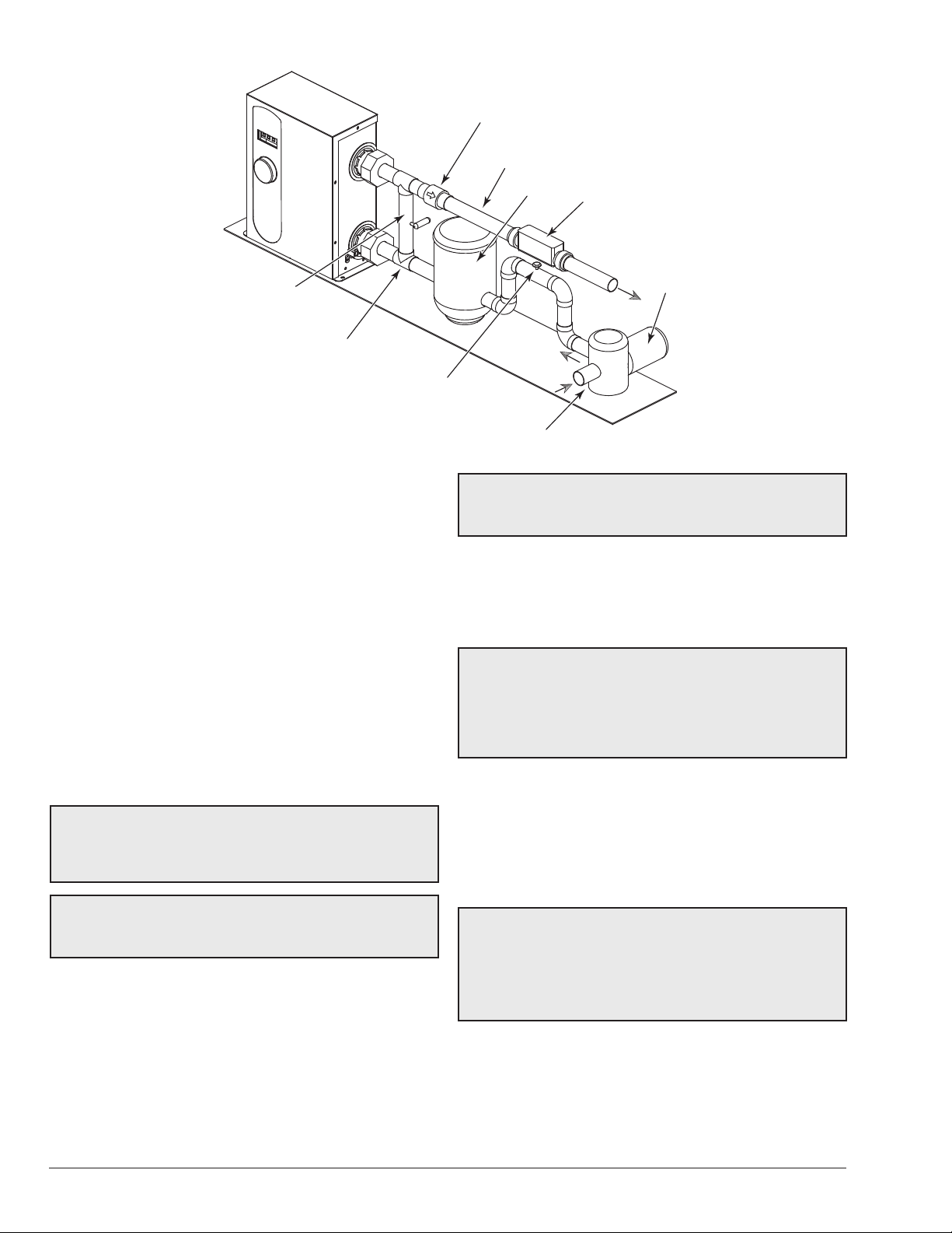
BYPASS
(CUSTOMER
INSTALLED)
DRAIN VALVE
(CUSTOMER
INSTALLED)
Figure 1. Spa/Pool Installation Diagram
GATE VALVE
8. FREEZE PROTECTION
If the heater is installed in a location subject to freezing
conditions, it is important to protect the water circuit from
freezing, just as should be done for the pump and lter.
System Drain-Down
1. Make sure the heater is disconnected or turned off.
2. With the pool pump OFF, loosen the PVC unions
supplied with the heater on both inlet and outlet pipes.
3. This should allow all of the water inside the heater to
drain out and prevent freeze damage to the heater.
9. ELECTRICAL
CONNECTIONS
WARNING: Please read these instructions
A
thoroughly and completely before installation and before
use. Failure to do so could cause property damage or
serious personal injury, or death and void your warranty.
WARNING: Risk of electrical shock. More than one
A
disconnect switch may be required to de-energize the
equipment before servicing.
This product must be installed by a licensed and qualied
electrician in accordance with Article 680 of the National
Electrical Code, NFPA 70 and with the requirements of
the authority having jurisdiction and all applicable national,
state, provincial, and local electrical codes.
As with all electrical appli ances, under no circumstances
should you attempt to install, repair or disassemble this
heater without rst shutting o all power to the heater
directly at the fuse or breaker box.
CHECK VALVE
TO SPA/POOL
FILTER
FROM SPA/POOL
WARNING: Serious bod ily injury or death could
A
occur if you ignore shutting o all power to the heater at
the fuse or breaker box.
CHLORINATOR
PUMP
F10545
All wiring (wire gauge) and circuit protection (breakers)
must comply with the U.S. National Electrical Code (NEC)
in the U.S.A., or the Canadian Electrical Code (CEC) in
Canada. Failure to do so could result in property damage
and/or personal injury, and void your warranty.
NOTE: The Canadian Electrical Code generally requires
that all supply wires and corresponding circuit protection
(breakers) used for hot water heating applications be
sized to a minimum of 125% of the maximum current
rating of the heater (see model specications below for
details).
Before installing this product, ensure that the home has
sucient electrical power available to handle the maximum
amperage load of the applicable model. All heaters have
one (1) minute time delay on start. The heater will not
energize the elements until 15 gpm (57 lpm) is established.
A separate ground conductor for each incoming circuit is
required.
CAUTION: Make sure that the electrical connections
A
are correct and all wire connec tions are tight and secure.
Make sure that the correct breaker size and wire gauge
has been used. Make sure that the heater has been
connected to a ground in accordance with applicable
codes.
6
Page 7

BREAKER
BREAKER
BREAKER
BREAKER
BREAKER
BREAKER
BREAKER
MODEL ELS 0005 MODEL ELS 0011 MODEL ELS 0018 MODEL ELS 0027
IN REVIEW
UNCONTROLLED DOCUMENT IF PRINTED
E1 E1 & E2 E1 E2 E1 E2 E3
GRND
L2 L1
GRND
L2 L1
GRND
L2 L1
L2 L1
GRND
L2 L1
L2 L1
L2 L1
30
DOUBLE
POLE
30
60
DOUBLE
POLE
60
50
DOUBLE
POLE
50
5050
DOUBLE
POLE
5050
DOUBLE
POLE
5050
DOUBLE
POLE
DOUBLE
POLE
Figure 2. Wire Connection to Circuit Breakers
Properties
ELS 0005 ELS 0011 ELS 0018 ELS 0027
Models
Elements 1 2 2 3
Voltage 240 V 240 V 240 V 240 V
Frequency (HZ) 60 60 60 60
Power (kW) 5.5 11 18 27
Each Element Supply (kW) 5.5 5.5 (Qty 2) 9 (Qty 2) 9 (Qty 3)
Amp Draw per Element
(Nominal)
23 23 x 2 37.5 x 2 37.5 x 3
Total Amp Draw (Nominal) 23 46 75 112.5
Required Breaker
(min/max amps)
30/30 60/60 50/50 (Qty 2) 50/60 (Qty 3)
Electrical Service (amps) 100 150 150 200
Table B. Electrical Specication
5050
Properties
Models
ELS 0005 ELS 0011 ELS 0018 ELS 0027
Wire Gauge #10 #6 #8 #8
Wire Set 1 1 2 3
Breaker Amperage 30 60 50/50 (Qty 2) 50/60 (Qty 3)
Breaker Type Double Pole Double Pole Double Pole Double Pole
Breaker Quantity 1 1 2 3
Table C. Circuit Breaker Specication
Models ELS 0005 and 0011 display the inlet temperatures
10. OPERATION
Once the heater is installed, it can be used year-round.
The user MUST makes sure the pump is not disengaged
to allow it to run until the desired temperature setting is
reached.
The heater will function only when there is sucient ow
through it [15 gpm (57 lpm) minimum]. On the digital
control panel, press and hold the knob for ve (5) seconds
to check the ow rate in the unit.
on the GPM screen by turning the knob to the right. The
outlet temperature is displayed by turning the knob to the
left.
Models ELS 0018 and 0027 have the outlet and inlet
temperatures displayed at all times.
The unit also has a one (1) minute built-in TIME DELAY to
protect it from air in the lines and to avoid burning out the
elements as a result of it. When the unit senses sucient
water ow, it will automatically activate.
7
Page 8

11. CONTROL
IN REVIEW
UNCONTROLLED DOCUMENT IF PRINTED
Turn the control knob to set your desired temperature.
When the set tempera ture is reached the heater will go to
idle and the elements will not draw power.
NOTE: If the controls and display are active, they still
draw some power.
Digital Control Temperature Setting
The heater comes with a digital temperature control
located in the front panel that can be set from
40°-104°F (4°C-40°C) in one (1) degree increments by a
simple turn of the knob.
The heater is turned OFF by pushing the control knob
once. Hold the knob for two (2) seconds to switch from
Fahrenheit to Centigrade.
40°- 104°F 4°- 40°C
FOR CELSIUS DISPLAY:
PUSH BUTTON
FOR 2 SECONDS
TO TURN OFF
PUSH BUTTON ONCE
PRESS
2
SECONDS
40°- 104°F 4°-
FOR CELSIUS DISPLAY:
PUSH BUTTON
FOR 2 SECONDS
TO TURN OFF
PUSH BUTTON ONCE
PRESS
2
40°C
SECONDS
Figure 3. Digital Control for Models ELS 0005 and 0011 Figure 4. Digital Control for Models ELS 0018 and 0027
Code Description Action
E1 Inlet sensor has a short. Buttons do not function, no heat. Need to replace sensor.
E2 Outlet sensor has a short. Buttons do not function, no heat. Need to replace sensor.
E3 (ELS 27 only) Chamber #1 sensor short. The heater will continue to operate, continues to heat.
E4 (ELS 27 only) Chamber #2 sensor short. The heater will continue to operate, continues to heat.
E5
Remote wiring is in use. The master
external controller is not CFH.
The heater will not heat until the master control has a CFH.
Table D. Fault Codes
8
Page 9

IN REVIEW
UNCONTROLLED DOCUMENT IF PRINTED
12. REMOTE OPERATION
The heaters are equipped to work with external remote
controls. The unit can be connected to either a toggle
switch or the switch contacts of a third party remote. The
remote works by either making or breaking the circuit
created by the remote wiring.
Typically, a remote does not supply power to the heater, it
only provides a switching function to turn on/o the heater.
If your remote is supplying its own voltage to the heater, it
will not work with this heater and may damage the digital
circuit board.
Remote Control Wiring
Important installation notes for remote or external wiring
conguration.
• Remote wiring must be run in a separate conduit.
• Remote wiring must not be run parallel to high voltage
lines.
• For runs of under 30 ft. (9.1 m), remote wiring
should have stranded conductors with a minimum
of 22 AWG, 600V, cable twisting 1.5" to 2.5"
(3.8 cm to 6.4 cm) lay and jacketed.
• For runs over 30 ft. (9.1 m), the conductors should
be a minimum of 20 AWG, 600V, cable twisting 1.5"
to 2.5" (3.8 cm to 6.4 cm) lay that is shielded and
jacketed.
• Maximum cable length is 200 ft. (61 m).
Remote Control (On-O)
1. Turn on power to the heater.
2. For a remote control without its own sensor, set the
desired set point, for example 102°F (39°C).
3. For a remote control with its own sensor, set the
temperature to the highest setting available on the
control on the heater. The actual set point will be
controlled by the remote control.
4. Turn off and remove power from the heater.
5. On the "Remote Interface Harness", the supplied
two wires provide power out to either a toggle
switch or the switch contacts of a third party remote.
See Figure 5.
NOTE: Code E5 is displayed on the heater digital display
when remote wiring is in use and the master external
controller is not calling for heat (CFH). The heater will
not heat until the master control is CFH.
GPM
(lpm)
15 (57) 1.6 3.6
20 (76) 2.4 5.6
25 (95) 3.6 8.2
30 (114) 5.2 11.9
35 (132) 7.5 17.3
40 (151) 8.8 20.3
45 (170) 19.2 44.4
50 (189) 22.6 52.2
60 (227) 23.2 53.7
Pressure Drop
in PSI
Pressure Drop
in ft. of Head
ADD “POOL/SPA
WHERE NECESSARY
REMOTE” SWITCH HERE
Figure 5. Supplied Wires for the Remote Interface
Harness
Table E. Pressure Drop for Models ELS 0005 and 0011
GPM
(lpm)
15 (57) 2.1 4.8
20 (76) 2.8 6.6
25 (95) 3.4 8
30 (114) 5.6 12.8
35 (132) 7.2 16.5
40 (151) 8.9 20.5
45 (170) 14.1 32.7
50 (189) 17.4 40.3
60 (227) 21.4 49.5
Table F. Pressure Drop for Models ELS 0018 and 0027
Pressure Drop
in PSI
Pressure drop
in ft. of Head
9
Page 10

IN REVIEW
UNCONTROLLED DOCUMENT IF PRINTED
150K Inlet/Outlet Sensor, All Models 10K Sensor for Model 0027 Element 3 Only
Temp ºF/ºC Resistance Ω Temp ºF/ºC Resistance Ω
32 (0) 491399.3 32 (0) 31537
41 (5) 384009.2 41 (5) 24783
50 (10) 303720 50 (10) 19587
59 (15) 242375.9 59 (15) 15568
68 (20) 191172 68 (20) 12443
77 (25) 150000 77 (25) 10000
86 (30) 122049 86 (30) 8080
95 (35) 97403.8 95 (35) 6563
104 (40) 77394 104 (40) 5359
113 (45) 61780.2 113 (45) 4398
122 (50) 49539.7 122 (50) 3628
Table G. Sensor Resistance
Models ELS 0005 and 0011
Heater Features Standard Values
Element resistance (check with at least one wire lead
disconnected from each element).
Delay in energizing elements (heater starts heating 1-minute
after powering up and sucient ow is recorded).
Turn on ow rate. 15 gpm ± 2 gpm (57 lpm ± 8 lpm)
Individual element current at max temp and max ow. 20.5 to 29.06 A
ECO trip point. 140°F (60°C)
To change temperature setting from Fahrenheit to Celsius. Press and hold the knob for 3-secs.
To display GPM. Press and hold the knob for 5-secs.
To display inlet and outlet water temperatures. On the display GPM screen, turning knob to the left shows
Models ELS 0018 and 0027
Heater Features Standard Values
Element resistance (check with at least one wire lead
disconnected from each element).
Delay in energizing elements (heater starts heating 1-minute
after powering up and sucient ow is recorded).
Turn on ow rate. 15 gpm ± 2 gpm (57 lpm ± 8 lpm)
Individual element current at max temp and max ow. 31.7 to 40.2 A
ECO trip point. 140°F (60°C)
To change temperature setting from Fahrenheit to Celsius. Press and hold the knob for 3-secs.
To display GPM. Press and hold the knob for 5-secs.
Inlet and outlet water temperatures. The inlet and outlet temperatures are displayed at all times.
Table H. E3T Electric Heater Features
9.97 to 11.6 Ω
1-minute ± 30 secs.
inlet water temperature and turning it to the left shows outlet
water temperature.
6.10 to 7.11 Ω
1-minute± 30-secs.
10
Page 11

13. TROUBLESHOOTING
IN REVIEW
UNCONTROLLED DOCUMENT IF PRINTED
Nothing happens when the
thermostat is turned on.
It takes a long time to heat the spa.
Spa does not reach temperature. Low ow Check lter, skimmer basket, pump.
Heating element continuously
burning out.
Fuses blow or circuit breaker opens.
Problem Cause Solution
1. Check lter, skimmer basket, pump.
2. If a 2-speed pump is used, turn to high speed.
Low ow
High limit has tripped Push the reset button on the limit.
Thermostat not calling for heat Turn thermostat to higher temperature.
Low input voltage Call the electric company.
Undersized heater
Heat loss from poor weather
conditions (cold, high winds)
Defective heating element Call an electrician.
High input voltage Call the electric company.
Poor water chemistry See "WATER CHEMISTRY" on page 4.
Heating element split open Over-acid condition. Watch pH, add acid slowly.
Shorted heating elements Replace element.
Undersized wire Replace eld wiring.
3. Press and hold the knob for 5-seconds. Make sure
the ow rate displayed on screen is at least 15 gpm
(57 lpm).
Calculate temperature in heat rise
°/hr. = Heater input (kw) x 410 divided by spa
gallonage (This does not take into account heat loss
due to weather).
Use an spa cover.
11
Page 12

14. WIRING DIAGRAMS
ELEMENT 2
HIGH LIMIT 1
1 3
1
2
HIGH LIMIT 2
ELEMENT 1
CPU
TRANSFORMER
VH1
VH2
HIGH LIMIT 3
ELEMENT 3
F1 —250V/1A Y1
1 3 1 2 1 2
WATER OUTLET, 150 kOhm
WATER INLET, 150 kOhm
1 3
CN5
VH5
VH6
CN8
REMOTE CONTROL WIRE
1
2
3
1 2
1 2
AC POWER SUPPLY
VH3
VH4
1 2 1 2
#1 THERMISTOR OF THE CHAMBER
#2 THERMISTOR OF THE CHAMBER
CN3
CN4
GND
GND
L1
L2
L1
L2
L1
L2
FLOW SENSOR
0027 ONLY
240VAC 1-PH 60 Hz
[SIZE 0027 ONLY]
1 3
1 3
1 21 2 1 2
WATER OUTLET,
WATER INLET,
1 3
L1
L2
GND
1 31 3
CPU
TRANSFORMER
VH1
VH2
CN1
CN2
CN4
VH3
VH4
CN8
1
2
3
REMOTE CONTROL WIRE
F1 —250V/1A
Y1
AC POWER SUPPLY
FLOW SENSOR
HIGH LIMIT 2
HIGH LIMIT 1
ELEMENT 2
ELEMENT 1
[SIZE 0011 ONLY]
150 kOhm
150 kOhm
240VAC 1-PH 60 Hz
IN REVIEW
UNCONTROLLED DOCUMENT IF PRINTED
12
Figure 6. Wiring Diagram for Models ELS 0005 and 0011
Figure 7. Wiring Diagram for Models ELS 0018 and 0027
Page 13

IN REVIEW
UNCONTROLLED DOCUMENT IF PRINTED
15. ILLUSTRATED PARTS LIST
MODELS
ELS 0005 and ELS 0011
15
1
14
12
MODELS
ELS 0018 and ELS 0027
3
5
6
4
8
7
9
10
1
15
13
11
16
12
14
2
5
7
8
6
10
9
13
4
11
16
13
Page 14

IN REVIEW
UNCONTROLLED DOCUMENT IF PRINTED
PART DESCRIPTION
1 017139F 017139F 017140F 017140F
Heating Element (Includes O-Ring)
2 N/A N/A N/A 017141F
Inlet Thermistor (Includes O-Ring)
3 017178F 017178F N/A N/A
Transformer 240V 60hZ
4 017161F 017161F 017161F 017161F
Water Sensor (Inlet & Outlet)
5 017143F 017143F 017144F(2) 017144F(3)
High Limit Manual Reset
6 017145F 017145F 017146F 017146F
Circuit Board with LED Display
7 017147F 017147F 017159F 017159F
Enclosure
8 017150F 017150F 017151F 017151F
Hall Effect Sensor
9 017152F 017152F 017160F 017160F
Terminal Block
10 017148F 017148F 017149F 017149F
11 017153F 017153F 017177F 017177F
12 017154F 017154F 017154F 017154F
13 017155F 017155F 017156F 017156F
14 017157F 017157F 017157F 017157F
15 017158F N/A 017158F N/A
16
Grounding Terminal
Triac 3-Wire
Knob
Flow Sensor
O-Rings (5)
Pipe Plug (Includes O-Ring)
Union (Set of 2) 017179F 017179F 017180F 017180F
ELS 0005 ELS 0011 ELS 0018 ELS 0027
14
Page 15

IN REVIEW
UNCONTROLLED DOCUMENT IF PRINTED
16. WARRANTY
LIMITED WARRANTY
SCOPE OF WARRANTY
Raypak, Inc. (Raypak) warrants to the original owner that the above model gas pool and spa heater (the
“Heater”) when installed in the contiguous 48 states of the United States of America with a pool or spa by
a properly licensed installer will be free from defects in materials and workmanship under normal use
and service for the Applicable Warranty Period. Under this Limited Warranty, Raypak will, at its option,
repair or furnish a replacement for any defective part of the HEATER. The repair or replacement will be
warranted for only the unexpired portion of the original Applicable Warranty Period, or the Extended
Warranty Period, as the case may be.
EFFECTIVE DATE
The Effective Date of Warranty coverage is the date of original installation if properly documented;
otherwise it is thirty (30) days after date of purchase, not to exceed one (1) year after date of
manufacture. All Applicable Warranty Periods specified in this Limited Warranty are measured from the
Effective Date.
APPLICABLE WARRANTY PERIOD – UNREGISTERED
If the HEATER is installed with a pool or spa, the Applicable Warranty Period is ninety (90) days from the
Effective Date, parts and labor, for the HEATER and component parts.
EXTENDED WARRANTY PERIOD – SERVICE PROFESSIONAL
If, within 90 days of the Effective Date, (i) the HEATER is installed
residential dwelling by a properly licensed installer (in accordance with applicable state and local laws
and regulations), and (ii) registered with Raypak (www.raypak.com) with an installation receipt attached
to such registration, then the Applicable Warranty Period is one (1) year from the Effective Date for the
HEATER and component parts, but specifically excluding the electrical heating element. The electrical
heating element will be warranted for a period of 90 days from the Effective Date. The HEATER will not
be eligible for the Extended Warranty Period if installed in a commercial application (hotel, condominium
or apartment common areas, etc.)
in a pool or spa at a single family
LABOR AND SHIPPING COSTS
This Limited Warranty covers the reasonable cost of labor for repairs or replacements covered by this
Limited Warranty, provided that said repairs or replacements are performed by a Raypak designated
service provider during the Applicable Warranty Period and Raypak has pre-authorized said repair or
replacement. This Limited Warranty does not cover any travel time or other labor costs. Furthermore,
unless applicable state law provides otherwise, this Limited Warranty does not cover any shipping costs
to and from the service provider or to or from the installation site. All of the foregoing costs and expenses
are your responsibility, unless applicable state law provides otherwise.
WARRANTY EXCLUSIONS
This Limited Warranty does NOT apply:
1. if the Heater has been moved from its original place of installation, or if the original owner no
longer owns the property where the original installation was made;
2. if the Heater is not properly installed with a pool or spa by a qualified licensed installer in
accordance with applicable local codes and ordinances, good trade practices, and the
manufacturer’s installation instructions;
3. if the rating plate(s) or serial number(s) are altered or removed;
4. if the Heater is modified in any way, or non-factory authorized accessories or other components
are used in conjunction with the Heater;
5. to damage, malfunctions or failures resulting from failure to properly install, operate or maintain
the Heater in accordance with the manufacturer’s instructions;
6. to damage, malfunctions or failures resulting from abuse, act of nature, accident, fire, flood,
freeze, lightning or the like;
7. to damage, malfunctions or failures resulting from connected system control devices;
8. to performance problems caused by improper sizing of the Heater or electric service voltage,
wiring or fusing;
15
Page 16

IN REVIEW
UNCONTROLLED DOCUMENT IF PRINTED
9. to use of any attachment, including without limitation, any energy saving device not authorized
by the manufacturer;
10. to damage, malfunctions or failures resulting from misuse or neglect, including but not limited to,
freeze-ups, operating the Heater with the cabinet door off, having flow restrictions or
obstructions between the Heater outlet and the pool/spa, electrolysis due to an improperly
installed salt chlorine generator, or not maintaining a proper chemical balance (PH level must be
between 7.4 and 7.8 and total alkalinity between 100 and 150 PPM. Total dissolved solids (TDS)
must be no greater than 3000 PPM. In salt water chlorinated pools, TDS must be no greater
than 6000 PPM).
HOW TO MAKE A WARRANTY CLAIM
You should immediately notify your dealer and provide proof of purchase model number serial number and date of
installation. Your dealer will contact Raypak for instructions regarding the claim and to determine the location of the
nearest authorized service center. If the dealer is not available, please contact Raypak warranty service at 805-278-
5300. When making a claim please be ready to supply the model number, serial number, date of original installation
and a description of the problem. Proper authorization MUST be obtained PRIOR to any repairs for the Limited
Warranty to apply. This Limited Warranty is VOID if the Heater is repaired or altered in any way by ANY
persons or agencies other than those authorized by Raypak. Raypak reserves the right at all times to inspect, or
require the return of, the defective Heater or component part and to verify warranty coverage at its factory
EXCLUSIVE WARRANTY-LIMITATION OF LIABILITY
THE LIMITED WARRANTY IS THE ONLY WARRANTY GIVEN BY RAYPAK IN CONNECTION WITH THE
HEATER AND ITS COMPONENT PARTS. NO ONE IS AUTHORIZED TO MAKE ANY OTHER WARRANTIES ON
RAYPAK’S BEHALF. ANY IMPLIED WARRANTIES, INCLUDING MERCHANTABILITY OR FITNESS FOR A
PARTICULAR PURPOSE, SHALL NOT EXTEND BEYOND THE APPLICABLE WARRANTY PERIOD SPECIFIED
ABOVE.
.
RAYPAK’S SOLE LIABILITY WITH RESPECT TO ANY DEFECT SHALL BE AS SET
FORTH IN THIS LIMITED WARRANTY. IT IS AGREED THAT RAYPAK SHALL HAVE
NO LIABILITY WHETHER UNDER THIS LIMITED WARRANTY OR IN CONTRACT,
TORT OR NEGLIGENCE OR OTHERWISE FOR CLAIMS FOR SPECIAL,
INCIDENTAL OR CONSEQUENTIAL DAMAGES (INCLUDING NO LIABILITY FOR
DAMAGE FROM WATER LEAKAGE), ALL OF WHICH ARE EXPRESSLY
EXCLUDED. SOME STATES DO NOT ALLOW LIMITATIONS ON HOW LONG AN
IMPLIED WARRANTY LASTS, OR FOR THE EXCLUSION OF INCIDENTAL OR
CONSEQUENTIAL DAMAGES, SO THE ABOVE LIMITATION OR EXCLUSION MAY
NOT APPLY TO YOU. THIS LIMITED WARRANTY GIVES YOU SPECIFIC LEGAL
RIGHTS, AND YOU MAY ALSO HAVE OTHER RIGHTS WHICH VARY FROM STATE
TO STATE.
We suggest you immediately record the model, serial number, date of original installation, receipt of purchase and
proof of installation by a qualified technician and retain this Limited Warranty Certificate in the event warranty service
is needed.
DO NOT RETURN THIS DOCUMENT TO RAYPAK. KEEP IT WITH YOUR POOL HEATER OR
BUSINESS RECORDS.
Register your product online at www.raypak.com/warranty
RAYPAK, INC., 2151 Eastman Avenue, Oxnard, CA 93030 • (805) 278-5300 FAX (800) 872-9725
Rheem Canada Ltd/Ltée. 125 Edgeware Road, Unit 1,Brampton, Ontario L6Y 0P5 CANADA
16
Page 17

ISO 9001
REGISTERED QUALITY MANAGEMENT SYSTEM
www.raypak.com
IN REVIEW
UNCONTROLLED DOCUMENT IF PRINTED
Raypak, Inc., 2151 Eastman Avenue, Oxnard, CA 93030 (805) 278-5300 Fax (805) 278-5468
Litho in U.S.A.
 Loading...