

Page 1
Raypak Installation Instruction
For Optional
E–6 Remote/Alarm Reset
CA T ALOG NO. 5000.56B
Effective: 04-09-08
Replaces: 12-01-02
PN 240706 Rev. 3
Page 2

Table of Contents
Contents Page
E-6 Remote Alarm/Reset 3
Important Safety Instructions 4
Introduction 4
Concept of Operation 4
Installation and Mounting 5
Mechanical Installation 5
Field Wiring (E–6 Remote Alarm Reset Switch) 6
Field Wiring (E–6 Remote Alarm Lamp) 7
Field Wiring (E–6 Remote Alarm Buzzer) 7
Field Wiring (Connecting the E–6 Boiler Alarm
with the E–6 Remote Alarm/Reset 8
Page 3
E–6 REMOTE ALARM/RESET
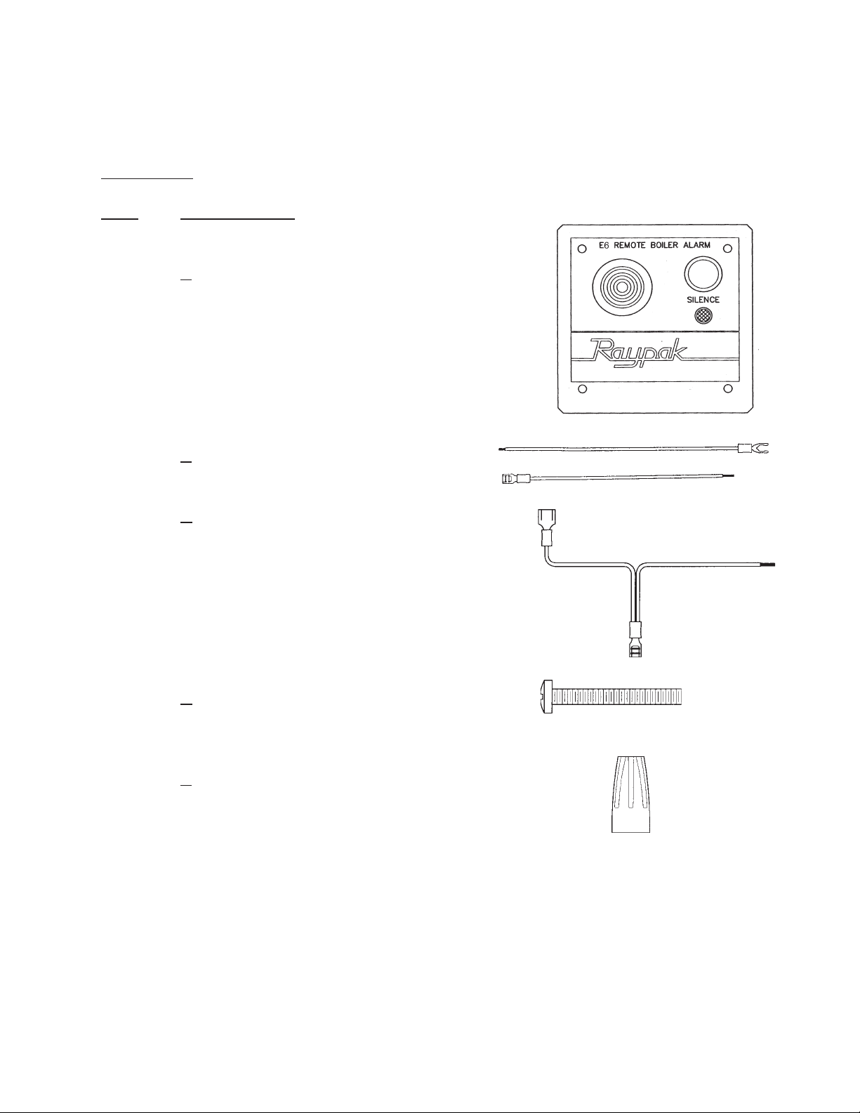
Check packaging for damage or missing components.
Kit Includes:
QTY. DESCRIPTION
1
2 B BELL WIRE ASSEMBLY
2 C BOILER ALARM
A E6 REMOTE ALARM/RESET PANEL
Includes:
FACE PLATE W/DECALS
LAMP W/WIRES
SWITCH W/WIRES
BUZZER W/WIRES
W/FORK CONNECTOR
SWITCH TEE WIRE ASSEMBLY
W/SPADE CONNECTOR
2 D 8 - 32 X 1-1/4" SCREWS
11 E WIRE NUT
3
Page 4

IMPORTANT SAFETY INSTRUCTIONS
IMPORTANT NOTICE: These instructions are intended for use by qualified personnel who
are specifically trained and experienced in the installation of this type of equipment and related system components. Installation and service personnel may be required by some states
to be licensed. If your state requires certification, be sure your contractor bears the appropriate license. Only qualified persons shall attempt to repair this equipment. Repair must be
according to these instruction.
WARNING: Improper installation, adjustment, alteration, service or maintenance may damage the equipment, create a hazard resulting in asphyxiation, explosion, fire, electric shock,
personal injury or property damage, and will void the warranty.
CAUTION: MORE THAN ONE (1) SUPPL Y SOURCE. THIS APPLIANCE HAS PROVISIONS
TO BE CONNECTED TO MORE THAN ONE (1) SUPPL Y SOURCE. TO REDUCE THE RISK
OF ELECTRIC SHOCK, DISCONNECT ALL SUCH CONNECTIONS BEFORE SERVICING.
CAUTION: RISK OF ELECTRIC SHOCK. MORE THAN ONE (1) DISCONNECT SWITCH
MAY BE REQUIRED TO DE-ENERGIZE THE EQUIPMENT BEFORE SERVICING.
NOTE: Minimum 18 A WG , 105°C, stranded wire must be used for all low volt age (less than 30
volts) external connections to the unit. Solid conductors should not be used because they can
cause excessive tension on contact points. Install conduit as appropriate. All high voltage wires
must be the same size (105°C, stranded wire) as the ones on the unit or larger.
INTRODUCTION
This product is designed for easy installation and operation. The following instructions and
information will aid you in the integration of this unit into your E–6 BOILER ALARM system.
Access to a copy of the owners manual for the main E–6 unit in addition to these instructions is
necessary and required. Af ter reviewing both manuals, installation will be quick and easy . Be
sure to read and follow all cautions, warnings, and important notices to protect against property
damage or personal injury .
CONCEPT OF OPERATION
The E–6 REMOTE/ALARM RESET is remotely accessible alarm panel for the E–6 BOILER
ALARM. This unit utilizes a buzzer/light combination remotely located (i.e., in a nearby office or
maintenance room) from the boiler room where the boiler and E–6 are located. It is also equipped
with a reset switch that can disable the audio alarm without the need for direct access to the E–
6 itself.
4
Page 5

INST ALLA TION AND MOUNTING
The panel is designed to be installed as a face plate for a standard 4x4 junction box. The
junction box (not included) should be located where the reset panel can be accessed and
seen from the best range of locations within the room.
Selection of a suitable location for the installation should include building code restrictions,
access and visibility . Comply to all applicable building codes for your area. Make sure that the
panel can be easily reached to reset the audible alarms. Choose a location that the alarm panel
light can be easily seen from all directions.
NOTE: The audio alarms can be reset from the main E6 unit leaving only the light on the
remote panel showing a fault. Do not assume that the audio alarm must be active to indicate
a potential problem.
MECHANICAL INSTALLATION
The junction box can be mounted in several ways to accommodate the reset panel. Directly on a suitable vertical surface mounted from the back of the box, with the front face flush
to a wall surface, or internal to the wall surface. The front of the junction box can be as far as
one inch from the wall surface using the hardware included. Make sure that field wiring (Not
included) can be run between the location chosen for the remote and main E6 unit within the
code restriction for your area. The wall hole size for the junction box must be limited to less
than half an inch from the edge or the remote panel will not cover the entire opening.
Make sure to read and follow all warnings, cautions and instructions in this manual and the
operation manual that is included with the E6 BOILER ALARM.
5
Page 6

Field Wiring (E–6 Remote Alarm Reset Switch)
1. Follow all necessary safety precautions regarding electrical equipment.
2. Use copper conductors only . Use 18AWG stranded wire rated at 75°C (167°F) or better .
3. Conform to wire color codes for field wiring.
4. Open the door and remove the display panel mounted screws (remove the door if
necessary for access).
5. Remove the display to access the interior of the control box.
6. Remove the common (COM) lead from the reset switch and attach it to the insulated male
spade connector of one of the tee wire harnesses (included).
7. Connect the female spade connector of the wire harness to the common (COM) of the
reset switch.
8. Connect the stripped end the wire assembly and the field wire being used with a wire nut
(included).
9. Repeat steps (6) through (8) for the normally open (NO) connection of the reset switch.
REMOTE ALARM/RESET E6 BOILER ALARM
6
Page 7

Field Wiring (E–6 Remote Alarm Lamp)
NOTE: The bell connections of the E–6 Boiler Alarm are being used to energize the lamp
of the E–6 Remote/Alarm Reset.
10. Remove the mounting screws from the bell located on the bottom of the control box.
1 1. Connect each of the fork connectors of the two wire assemblies E to the terminals of
the bell. Do not remove the existing connections.
12. Feed the wire assemblies through the bottom of the control box with the existing wires
and remount the bell.
13. Connect field wiring to each wire assembly with a wire nut E.
REMOTE ALARM/RESET E6 BOILER ALARM
Field Wiring (E–6 Remote Alarm Buzzer)
14. Remove the wire nut connecting the red buzzer wire with the wire running to the E–6
PC board.
15. Add the red field wire to the connection and replace the wire nut.
16. Repeat (14) and (15) for the buzzers black wire.
17. Repeat (4) and (5) in reverse to reassemble the control box.
REMOTE ALARM/RESET E6 BOILER ALARM
7
Page 8

FIELD WIRING (Connecting the E–6 Boiler Alarm with the E–6 Remote Alarm/Reset)
1. All wiring for lamp, reset switch, and buzzer should now be connected to the E–6
Boiler Alarm and run to the 4X4 junction box being used to mount the E–6
Remote/Alarm.
2. Connect the female spade connectors of the two wire assemblies (included) to common
(COM) and normally open (NO) connections of the remote reset switch.
3. Using wire nuts (Included) attach each one of the leads of the lamp, reset switch, and
buzzer to the matching field wire connections from the E–6 BOILER ALARM.
NOTE: The lamp of the E–6 Remote Alarm/Reset is run in parallel with the vibrating bell
of the E–6 BOILER ALARM.
4. Attach the E–6 remote faceplate to the junction box (see the Preparation section of
INST ALLA TION AND MOUNTING).
8
Page 9

E6, Alarm Board Remote
9
Page 10

10
TO THE E6 BOILER ALARM
Page 11

www.raypak.com
Raypak, Inc., 2151 Eastman Avenue, Oxnard, CA 93030 (805) 278-5300 FAX (800) 872-9725
Litho in U.S.A.
 Loading...