

Page 1
Catalog No.: 5000.55B
Effective: 4-09-08
Replaces: 5-01-98
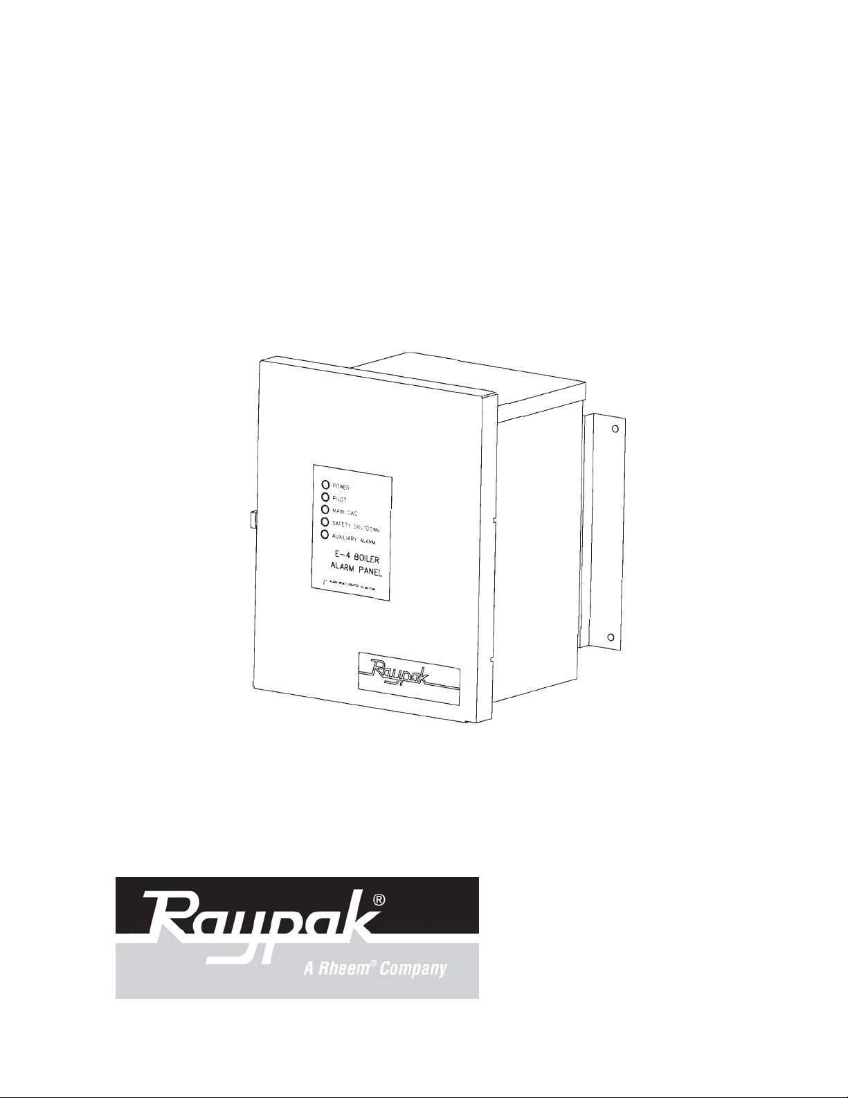
E–4 BOILER
ALARM ANNUNCIATOR
Installation and Operating Manual
PN 240691 Rev. 3
Page 2

E–4 BOILER ALARM/ANNUNCIATOR
Installation and Operating Manual
Before operating this product, please read these instructions completely .
2
Page 3

TABLE OF CONTENTS
Contents Page
Important Safety Instructions 4
Getting Started 5
Introduction 5
Optional Remote Alarm 5
Optional Auxiliary Alarm 5
Dimensions and Weight 6
Installation and Mounting 6
Mechanical Installation 6
Electrical Characteristics 6
Electrical Installation 6
Check Your Power Source 7
Wiring Power to the E-4 Boiler Alarm 7
Power Test 7
E-4 Boiler Alarm Indicator Lights 8
Field Wiring Connection Points 9
Optional Auxiliary Alarm Wiring 10
Remote Alarm Panel Wiring Diagram 11
Installation Verification Procedure 12
Illustrated Parts List 13
3
Page 4

E–4 BOILER ALARM/ANNUNCIA TOR
Contents
Item Quantity
E–4 Boiler Alarm/Annunciator , Installed on Boiler(s) As Ordered
Optional Equipment As Ordered
Check packaging for damaged or missing components.
IMPORTANT SAFETY INSTRUCTIONS
IMPORT ANT NOTICE: These instructions are intended for use by qualified personnel who are
specifically trained and experienced in the installation of this type of equipment and related system components. Installation and service personnel may be required by some states to be
licensed. If your state requires certification, be sure your contractor bears the appropriate license. Only qualified persons shall attempt to repair this equipment. Repair must be according
to these instructions.
WARNING: Improper installation, adjustment, alteration, service or maintenance may damage
the equipment, create a hazard resulting in asphyxiation, explosion, fire, electric shock, personal
injury or property damage, and will void the warranty .
CAUTION: MORE THAN ONE (1) SUPPL Y SOURCE. THIS APPLIANCE HAS PROVISIONS
TO BE CONNECTED TO MORE THAN ONE (1) SUPPL Y SOURCE. TO REDUCE THE RISK
OF ELECTRIC SHOCK, DISCONNECT ALL SUCH CONNECTIONS BEFORE SERVICING.
CAUTION: RISK OF ELECTRIC SHOCK. MORE THAN ONE (1) DISCONNECT SWITCH
MA Y BE REQUIRED TO DE-ENERGIZE THE EQUIPMENT BEFORE SERVICING.
NOTE: Minimum 18 A WG , 105°C, stranded wire must be used for all low volt age (less than 30
volts) external connections to the unit. Solid conductors should not be used because they can
cause excessive tension on contact points. Install conduit as appropriate. All high voltage wires
must be the same size (105°C, stranded wire) as the ones on the unit or larger.
PLEASE REGISTER
Before proceeding any further, please t ake a moment to complete the enclosed user registration form and mail it to
Raypak, Inc. Department E-4, 2151 Eastman Avenue, Oxnard, CA 93030
4
Page 5

GETTING STARTED
Thank you for selecting the Raypak E-4 Boiler Alarm. It is our sincere hope that you will enjoy it's outstanding
design and ease of use. To learn about the E-4 Boiler Alarm, simply inst all it as shown in these instructions, and
then start using it. The following information will help familiarize you with the E-4 and will acquaint you with the
installation procedure.
INTRODUCTION
The E-4 Boiler alarm is a solid state electronic boiler status indicator and alarm panel that has been engineered
to enhance safety, simplify troubleshooting and minimize equipment down time. The E-4 Boiler Alarm is comprised of an alarm circuit board, a NEMA 3R rated rainproof enclosure, and the following components:
Standard Indicator Lights:
Power Green, indicates that power is available to the alarm unit.
Pilot Amber, indicates that the Pilot Valve circuit has been energized.
Main Gas Green, indicates that the Main Gas Valve has been energized.
Safety Shutdown Red, indicates a safety shutdown has occurred. Either the 24 or 120 VAC
signal is missing from the safety circuit.
Auxiliary Alarm Red, indicates a safety failure after a predetermined time delay has
expired. (Activated by the optional Auxiliary Alarm).
Alarm and Bell:
Mechanical Alarm Bell Standard bell: 3", optional bell: 4". Upon alarm activation, the mechanical
bell rings until the alarm is acknowledged by pressing the alarm silence
switch.
Electric Alarm Buzzer Upon alarm activation, the buzzer sounds a steady tone for ten seconds
and then pulses on and off at 2 cycles per second until acknowledged.
Alarm Silence Switch:
Located on the bottom of the enclosure, the alarm silence switch is a momentary switch used to silence
the alarm bell and buzzer after an alarm condition occurs. Once acknowledged, the bell and buzzer will
cease sounding until a new alarm condition occurs. The appropriate alarm indicator light (Safety Shut
down or Auxiliary Alarm) will remain lit until the alarm condition has been cleared.
Optional Remote Alarm Panel
The Optional Remote Alarm Panel provides a mounting panel and the necessary electrical components to
monitor the E-4 Boiler alarm at a remote location. It includes the following:
Electric Alarm Buzzer Provides an audible indication of a fault. See description above.
Indicator Light Red, indicates that a boiler fault has occurred.
Silence Switch Silences the electric alarm buzzers and the mechanical bell.
Optional Auxiliary Alarm Board
The Optional Auxiliary Alarm Board, when installed, activates the Auxiliary Alarm light on the standard boiler
alarm circuit board upon a fault in the monitored circuit. The Optional Auxiliary Alarm provides a user adjustable
time delay from 5 to 60 secs during which the Auxiliary Alarm verifies that the alarm condition is "locked in". The
Optional Auxiliary Alarm can be used to monitor a flow switch, low water cutoff switch or any other circuit that is
susceptible to spurious alarms due to transitory fault conditions.
5
Page 6

DIMENSIONS AND WEIGHT
14" W 10 1/4 lbs.
10" H
7" D
INST ALLA TION AND MOUNTING
If the E–4 Boiler Alarm was not mounted on the boiler by the factory, care should be taken to select a suitable
mounting location. The Boiler Alarm should be mounted on a solid and permanent base. The Boiler alarm enclosure is NEMA 3R rated, rain proof/sleet resistant and can be mounted outdoors if required. The unit should be
readily accessible for maintenance and installation purposes, and should be mounted so that the indicating lights
are at a height and location convenient for viewing.
MECHANICAL INSTALLATION
Install the E–4 Boiler Alarm within 10 feet of the boiler . The E–4 Boiler Alarm must be mounted vertically with the
conduit holes facing downward. The conduit holes are sized to accommodate standard conduit fittings. If additional
or larger conduit fittings are required, the holes must be located on the bottom of the module.
Mount the E–4 Boiler Alarm using the mounting bracket and appropriate 3/8” or 1/4” diameter hardware in four (4)
places.
A minimum of eighteen (18) inches clearance from the front, and six (6) inches clearance on all other sides is
required for service access. The hinged right side of the box should be installed with sufficient clearance (minimum
3” from bolt hole on the right side) to open the cover.
An electrical distribution sub-panel containing the disconnect switches and surge suppressors is required at or
near the equipment location(s).
T o access the control board, remove the interior panel by unscrewing the two (2) decal p anel fasteners.
INST ALL CONDUIT AS APPROPRIATE.
ELECTRICAL CHARACTERISTICS
Alarm Module - 120 V AC, 0.25A, 60 Hz
Monitors - 120 or 24 V AC
ELECTRICAL INSTALLATION
120 V AC FEEDER CIRCUITS
Install a surge protection device sized appropriately for your installation at each module.
Install a separate disconnect means for each load. Use appropriately sized wire for equipment as defined by NEC
and/or local code. All primary wiring should be 125% of minimum rating.
It is strongly recommended that the E–4 Boiler Alarm and the boiler be supplied from the same source power .
6
Page 7

CHECK YOUR POWER SOURCE
CIRCUIT BREAKER P ANEL
AC = 108 Volt s AC Minimum, 132 Volts MAX
AB = 108 Volts AC Minimum, 132 Volt s MAX
BC = Must be less than 1.0 Volts AC
WIRING POWER TO THE E–4 BOILER ALARM
• Observe Polarity
• Observe proper wire colors while making electrical connections.
• Provide an external surge suppressor capable of maintaining system integrity .
• Provide overload protection and a disconnect means for equipment serviceability as required by local
and state code.
• Conduit cannot be used as the ground. (There must be a “WIRED” ground.)
• V ery Important: A grounding electrode conductor shall be used to connect the equipment grounding
conductors, the equipment enclosures, and where the system is grounded, the grounded service
conductor to the grounding electrode.
POWER TEST
CHECK POWER
Utilizing a Volt-Ohm-Meter (VOM), monitor the following on the E–4 Boiler Alarm for proper voltage levels. Check
at connector P1 and single point ground (SPG).
POWER TEST
INDICATION
From: To:
Pin 1 Pin 2 108 V AC to 132 VAC
Pin 1 SPG 108 V AC to 132 V AC
Pin 2 SPG less than 1 VAC
7
Page 8

E–4 Boiler Alarm Indicator Lights
POWER
PILOT
MAIN GAS
SAFETY SHUTDOWN
AUXILIARY ALARM
ALARM PANEL
ALARM RESET LOCATED ON BOTTOM
E–4 BOILER
INDICATOR LIGHTS
POWER
PILOT
MAIN GAS
SAFETY SHUTDOWN
AUXILIARY ALARM
(Green) Indicates that 120 VAC is being supplied to the E–4 Boiler Alarm Board.
(Amber) Indicates that the pilot valve circuit has been energized.
(Greed) Indicates that the main gas valve has been energized.
(Red) Indicates that a safety shutdown has occurred. Either the 24 or 120 VAC
signal from the safety circuit that is being monitored by the Boiler alarm is missing.
The Boiler Alarm does not indicate what component in the safety chain has been
disrupted. Standard troubleshooting techniques must be applied to determine the
cause of the fault.
(Red) Indicates that either a safety failure of the boiler or failure in the monitored
circuit has occurred (depending or wiring configuration). The Auxiliary Alarm light
is energized by the Optional Auxiliary Alarm Board after a user adjustable time
delay has expired. The Auxiliary Alarm may be wired to monitor the low water
cutoff, flow switch or any other component susceptible to spurious alarms.
8
Page 9

Field Wiring Connection Points
Note: Tighten terminal strip clamping screws to 4 in-lbs. Breakage from over torquing is not covered under
warranty .
Use 18 GA stranded copper conductors only .
For supply connections, use wires sized on the basis of 60°C ampacity and rated a min. 90°C (194°F).
9
Page 10

Optional Auxiliary Alarm Wiring (E-6)
The Auxiliary Alarm is available as an option for piggy back mounting on the standard board. It provides the
Auxiliary Alarm cont acts with an adjust able time delay from 5 to 60 seconds and is designed for local code
compliance.
Refer to Catalog number 5000.64 for installation instructions.
10
Page 11

WIRING DIAGRAM
11
Page 12

INSTALLATION VERIFICATION PROCEDURE
REGISTER
Before proceeding any further, please verify that the user registration form has been completed and mailed.
MECHANICAL INSTALLATION
Verify that the mechanical installation has been completed in accordance with the instructions.
SYSTEM MODULE INSTALLATION
Verify electrical power wiring connections.
Verify electrical connection torque requirements.
Verify Power Test has been completed successfully.
12
Page 13

1-S
CALL OUT DESCRIPTION PART NO.
1-C Control P. C. Board 005639F
2-C Second Alarm Kit 005635
3-C Buzzer 005640F
4-C Reset Switch 005641F
5-C 3" Bell 005642F
4" Bell 005643F
6-C Remote Alarm & Reset Switch Kit 005632
1-S Door Assy. w/Window 005636F
2-S Side Mount Bracket 005644F
4-C
2-S
1-C
2-C
4-C
3-C
5-C
6-C
13
Page 14

LIMITED WARRANTY
E-4 & Accessories
SCOPE OF WARRANTY :
Raypak, Inc. ("Raypak") warrants to the original owner the Control System to be free from defects in materials and
workmanship under normal use and service for the applicable warranty period. In accordance with the terms of this Limited
Warranty, RAYPAK will furnish a replacement or repair, at our option, any defective part which fails in normal use and service
during the applicable warranty period. The replacement or repair will be warranted for only the unexpired portion of the original
Warranty Period.
APPLICABLE WARRANTY PERIOD
The effective date of warranty coverage is the date of original installation, of the Control System, by a qualified electrician
or by a RAYPAK authorized service technician. The Applicable Warranty Period is one (1) year from the effective date.
WARRANTY EXCLUSIONS
This Limited Warranty does not apply:
1. if the control system is not properly installed by a qualified technician in accordance with manufacturer's installation
instructions, applicable codes, ordinances and good trade practices,
2. to damage or malfunctions resulting from failure to properly install, operate or maintain the system in accordance
with the manufacturer's instructions;
3. if the rating plate(s) or serial number(s) are altered, defaced or removed;
4. if the System is modified in any way or used with any non-factory authorized accessories or components;
5. to damage or failure from abuse, accident, act of nature, fire, flood, freezing or the like;
6. to accessories, rubber or plastic parts, light bulbs or glass parts;
7. if the System is moved from its original installation site; or if the original owner no longer owns the site or the System.
LABOR AND SHIPPING COSTS
This Limited Warranty does not cover labor costs for service, removal or reinstallation of any part nor shipping charges
to or from RAYPAK'S designated repair center or to or from the installation site. All such costs are your responsibility.
HOW TO MAKE A WARRANTY CLAIM
To make a warranty claim, promptly ship (postage prepaid) or carry the defective part to a designated RAYPAK
Service Dealer or Service Station in the United States, supplying proof of purchase and date of installation and the model and
serial numbers. If you cannot locate a dealer, contact RAYPAK'S Service Department at the address/telephone listed below.
Raypak reserves the right at all times to inspect the claimed defect and verify warranty coverage at its factory.
EXCLUSIVE WARRANTY - LIMITATION OF LIABILITY
This is the only warranty given by RAYPAK. No one is authorized to make any other warranties on Raypak's behalf.
ANY IMPLIED WARRANTIES, INCLUDING MERCHANTABILITY OR FITNESS FOR A PARTICULAR PURPOSE, SHALL NOT
EXTEND BEYOND THE APPLICABLE WARRANTY PERIOD SPECIFIED ABOVE. RAYPAK'S SOLE LIABILITY WITH RESPECT
TO ANY DEFECT SHALL BE AS SET FORTH IN THIS LIMITED WARRANTY. ANY CLAIMS FOR INCIDENTAL OR CONSEQUENTIAL
DAMAGES (INCLUDING DAMAGE FROM WATER LEAKAGE) ARE EXCLUDED. Some states do not allow limitations on how long
an implied warranty lasts, or for the exclusion of incidental or consequential damages, so the above limitation or exclusion
may not apply to you.
THIS LIMITED WARRANTY GIVES YOU SPECIFIC LEGAL RIGHTS, AND YOU MAY ALSO HAVE OTHER RIGHTS
WHICH VARY FROM STATE TO STATE.
We suggest you immediately complete the information below and retain this Limited Warranty Certificate in case warranty
service is needed.
RAYPAK, INC. SERVICE DEPARTMENT
2151 Eastman Avenue, Oxnard, CA 93030
Telephone: (805) 278-5300 FAX (800) 872-9725
The following information must be provided when you write or call:
_____________________________________________ _______________________________________________
Original Owner Daytime Telephone Number
_________________________________________________________________________________________________
Complete Mailing Address
_____________________________________________ ________________________________________________
City State Zip Code Installation Site
______________________________________________ _______________________________________________
Model Number Contractor/Installer
______________________________________________ _______________________________________________
Date of Installation Serial Number
Raypak, Inc., 2151 Eastman Avenue, Oxnard, CA 93030 (805) 278-5300- Fax (800) 872-9725
Litho in U.S.A.
Page 15

www.raypak.com
Raypak, Inc., 2151 Eastman Avenue, Oxnard, CA 93030 (805) 278-5300- Fax (800) 872-9725
Litho in U.S.A.
 Loading...