

Page 1
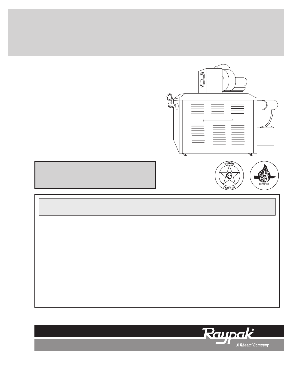
INSTALLATION & OPERATING
INSTRUCTIONS
CATALOG NO. 2000.54H Effective: 03-04-09 Replaces: 12-18-07 P/N 240608 Rev. 9
WARNING: If these instructions are not followed exactly, a fire or explosion may
result causing property damage, personal injury or death
.
FOR YOUR SAFETY: Do not store or use gasoline or other flammable vapors and
liquids or other combustible materials in the vicinity of this or any other appliance. To
do so may result in an explosion or fire.
WHAT TO DO IF YOU SMELL GAS:
• Do not try to light any appliance.
• Do not touch any electrical switch; do not use any phone in your building.
• Immediately call your gas supplier from a neighbor's phone. Follow the gas
supplier's instructions.
• If you cannot reach your gas supplier, call the fire department.
Installation and service must be performed by a qualified installer, service agency or
the gas supplier.
This manual should be maintained in legible condition and kept adjacent to the heater or in another safe place for
future reference.
For Raytherm™ Models
0514–4001 – Type D
Induced
Draft
Assembly
Page 2

2
Rev. 9 reflects the following: Changes to: Paragraph one of the General Specifications section on page 5; Fig. 4 on page
8 and Fig. 10 on page 12.
Page 3

Warnings 4
Pay Attention to These Terms 4
Receiving Equipment 5
General Specifications 5
Installation 6
Mounting the Assembly 6
Venting 6
Electrical Wiring 8
Wiring Diagram—Existing Heater 9
Wiring Diagram—Heater with Installed
Power Vent 10
Sequence of Operation 11
Start-up Procedures 11
Typical S8600 Ignition System 11
Controls 12
Blower Motor Contactor &
Purge Relay 12
Draft-Proving Switch 12
Positions of Discharge 12
Models 0514–1826 Only 12
Dimensions 14
CONTENTS
3
Page 4
DANGER:
Indicates the presence of immediate hazards which will cause severe
personal injury, death or substantial property damage if ignored.
WARNING:
Indicates the presence of hazards or unsafe practices which could cause
severe personal injury, death or substantial property damage if ignored.
CAUTION:
Indicates the presence of hazards or unsafe practices which could cause
minor personal injury or product or property damage if ignored.
NOTE:
Indicates special instructions on installation, operation, or maintenance which
are important but not related to personal injury hazards.
Warnings
Pay Attention to These Terms
4
NOTE: Minimum 18 AWG, 105°C, stranded wire
must be used for all low voltage (less than 30 volts)
external connections to the unit. Solid conductors
should not be used because they can cause
excessive tension on contact points. Install conduit
as appropriate. All high voltage wires must be the
same size (105°C, stranded wire) as the ones on the
unit or larger.
Page 5
Receiving Equipment
On receipt of your equipment it is suggested that you
visually check for external damage to the carton. If the
carton is damaged, it is suggested that a note be made
on the Bill of Lading when signing for equipment.
Remove the complete assembly from the carton and if
it is damaged report the damage to the carrier immediately.
Be sure that you receive the number of packages indicated on the Bill of Lading. Claims for shortages and
damages must be filed with the carrier by consignee.
Purchased parts are subject to replacement only
under the manufacturer's warranty. Debits for defective replacement parts will not be accepted and
defective parts will be replaced in kind only per our
standard warranties.
When ordering parts, you must specify Model and
Serial Number of the heater. When ordering under
warranty conditions, you must also specify date of
installation.
Raypak recommends that this manual be reviewed
thoroughly before installing the Type D Assembly. If
there are any questions which this manual does not
answer, please contact your local Raypak
Representative.
General Specifications
The Type D Assembly is certified by the Canadian
Standard Association (CSA) and conforms to the
American National Standard ANSI Z21.13/CSA 4.9 latest edition for hot water boiler.
The Type D Assembly is a fan-assisted combustion
system designed for application to Raytherm type H,
WH, and P models 0514 through 4001. When installed
as directed, the heater is capable of operating in applications such as through-the-wall venting and reduced
horizontal and vertical vent pipe sizes in new and
existing installations.
The Type D Assembly includes a blower with a 120
VAC/60 Hz 1 Ph motor, a plenum complete with a draft
control device, a draft-proving switch and a motor
5
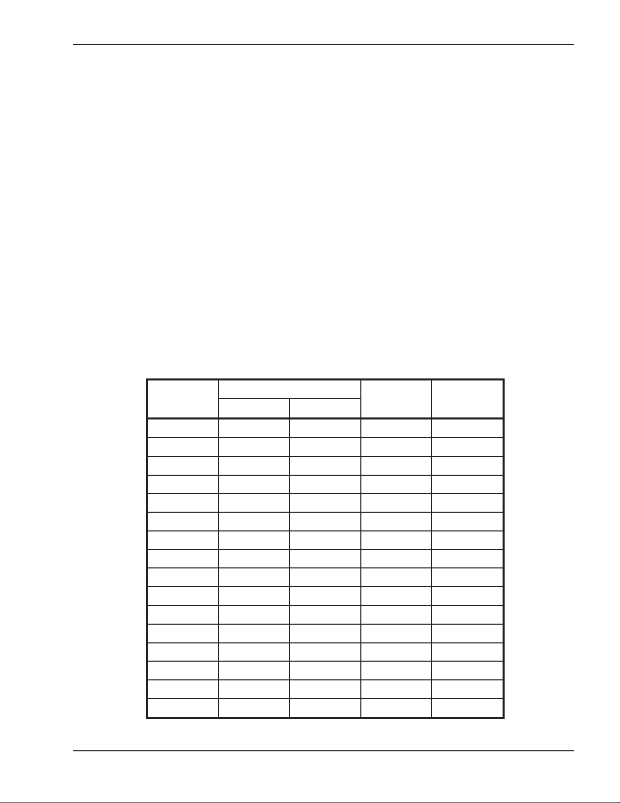
Model No.
MBTUH
Min. Conn.
Dia. (in.)
Part No.
Input Output
0514 512 419 7 065128
0624 627 514 7 065129
0724 726 595 7 065130
0824 825 677 8 065131
0962 962 789 8 065351
1125 1125 922 8 065352
1223 1223 1002 8 065353
1336 1336 1096 10 065354
1468 1467 1203 10 065355
1631 1630 1337 10 065356
1826 1826 1497 10 065357
2100 2100 1722 14 005627
2500 2499 2047 14 005627
3001 3000 2460 16 005629
3500 3500 2870 16 005630
4001 4000 3280 18 005631
Table A: Draft Assembly Application and Part Numbers
Page 6

6
relay with post-purge capability. When provided for
field mounting, the assembly is equipped with a wire
harness.
Installation
The equipment must be installed in accordance with
local codes, or in the absence of local codes with the
latest edition of the National Fuel Gas Code, ANSI
Z223.1, the National Electrical Code, ANSI/NFPA 70.
In Canada, Installations must conform to correct
CAN/CSA B149 and to the latest Canadian Electrical
CODE PART 1.
The equipment must be installed in accordance with
local installation regulations. These must be carefully
followed in all cases. Authorities having jurisdiction
shall be consulted before installations are made.
Mounting the Assembly
All Models
1. The standard indoor jacket top and flue collector
for the particular heater model are used.
2. Install the baffle assembly supplied in the flue outlet. The baffle must be installed with the mounting
arms positioned at the sides of the opening parallel to the sides of the heater.
3. Mount the plenum assembly on the jacket top
using the silicone sealant and screws provided.
Use a #28 drill (.1405" dia.) to drill the eight (8)
holes needed for the mounting screws. The
assembly should be positioned to the rear of the
heater.
4. Connect the wire harness to the heater junction
box. Complete wiring in accordance with the
enclosed wiring diagram.
Models 2100–4001
The Type D Assembly for models 2100 through 4001
is installed directly on the top panel above the built-in
drafthood. The adapter plate is anchored to the top
using the silicone sealant and screws provided. Refer
to Fig. 2.
Venting
The Type D Assembly can be used with various vent
pipe diameters. This versatility is based on using transition pieces or adapters from the fan outlet to the vent
pipe diameter. It is suggested that whenever there is a
change in size that a smooth transition piece be used.
Refer to Fig. 4.
The Type D Assembly operates with a positive vent
static pressure and with a vent gas temperature that
avoids excessive condensate production in the vent,
and as such it is listed as a CATEGORY III appliance.
Blower Multi-poise 0° to 90°
Plenum
Assembly
Jacket
To p
Blower
Fig. 1: Draft Assembly Mounting, Models 0514–1826
Adapter
Panel
Right Side
Fig. 2: Draft Assembly Mounting, Models 2100–4001
Page 7

7
Fig. 3: Minimum Clearances from Vent/Air Inlet Terminations – Indoor and Outdoor Installations
Table B: Vent/Air Inlet Termination Clearances
U.S. Installations
Clearance above grade, veranda, porch,
A
deck, or balcony
Clearance to window or door that may be
B
opened
4 ft (1.2m) below or to side
1 ft (30 cm) 1 ft (30 cm)
of opening; 1 foot (30 cm)
above opening
1
Canadian Installations
3 ft (91 cm)
2
C Clearance to permanently closed window **
Vertical clearance to ventilated soffit located
above the terminal within a horizontal dis-
D
tance of 2 ft (61cm) from the centerline of the
5 ft (1.5m) *
terminal
E Clearance to unventilated soffit **
F Clearance to outside corner **
G Clearance to inside corner 6 ft (1.83m) *
Clearance to each side of center line ex-
H
tended above meter/regulator assembly
*
3 ft (91 cm) within a height
15 ft above the me-
ter/regulator assembly
I Clearance to service regulator vent outlet * 6 ft (1.83m)
Clearance to non-mechanical air supply inlet
to building or the combustion air inlet to any
J
other appliance
K Clearance to mechanical air supply inlet
Clearance above paved sidewalk or paved
L
driveway located on public property
Clearance under veranda, porch, deck or
M
balcony
1
In accordance with the current ANSI Z223.1/NFPA 54 National Fuel Gas Code
2
In accordance with the current CAN/CGA-B149 Installation Codes
t Vent terminal shall not terminate dir ectly above sidewalk or paved driveway located between 2 single family dwellings that serves
both dwellings
TT Permitted only if veranda, porch, deck, or balcony is fully open on a mi nimum of two sides beneath the floor and top of terminal and
underside of veranda, porch, deck or balcony is gr eater than 1 ft (30cm)
* Clearances in accordance with local installation codes and the requirements of the gas supplier
4 ft (1.2m) below or to side
of opening; 1 ft (30 cm)
above opening
3 ft (91 cm) above if within
10 ft (3m) horizontally
7 ft (2.13m)
* 12 in. (30 cm) TT
3 ft (91 cm)
6 ft (1.83m)
7 ft (2.13m) t
Page 8

8
Models 0514–0724 Models 0824–1223 Models 1336–1826
Fig. 4: Draft Assembly with Various Vent Pipe Diameters and Transitions
The exception is when the assembly is connected to a
vertical vent of sufficient height to generate a negative
draft in the system. In this case, consult sizing guide or
the factory.
The Type D Assembly is suitable for through-the-wall
venting, and for connection to smaller size vent pipes
and breaching other than the standard atmospheric
appliance.
Fig. 5: Draft Assembly Through-The-Wall Venting
Electrical Wiring
The type D Assembly includes a wire harness which
provides quick connections with the respective controls in the heater control box. The harness is of
sufficient length to fit the heater for which it is sized.
Reference the wiring diagram supplied with each
heater for actual connections.
Fig. 6: Draft Assembly Wire Harness
WARNING: No substitutions of flue pipe or vent
cap material are allowed. Such substitutions would
jeopardize the safety and health of inhabitants.
Termination
The flue direct vent cap MUST be mounted on the exterior of the building. The direct vent cap cannot be
installed in a well or below grade. The direct vent cap
must be installed at least 1 ft above ground level and
above normal snow levels. The Raypak-approved
stainless steel flue direct vent cap must be used (sales
order option D-15).
8" x 7"
Transition
8" Dia.
Jacket Top
Jacket Top
12” MIN.
10" Dia.
Jacket Top
FLUE EXHAUST
VENT CAP
Page 9

9
Wiring Diagram—Existing Heater
Page 10

10
Wiring Diagram—Heater with Installed Power Vent
Note: Use the wiring diagram provided with the heater
Page 11

11
Sequence of Operation
On call for heat, the induced draft fan (and heater
pump) start. When the draft-proving switch and the
flow switch circuits close, the ignition system, consisting of an electronic spark module, pilot gas system
and flame sensor, are energized.
When all safety circuits are proven, the automatic
main gas valves will open and the heater will operate.
When the operating temperature control circuit is satisfied, the heater will shut down and the fan will
operate for a selected post-purge period.
Start-up Procedures
The water, gas and electrical systems of the heater
should be completed and checked as described in the
heater installation manual and associated documents.
Typical S8600 Ignition System
1. Turn on power to the heater with the manual main
gas valve and pilot gas valve off. The electric
power supply requirements are:
• 1/3 hp, 120 VAC, 60 Hz, 1 Ph, 5.8 amp fan
motor for models 0514 through 1336.
• 1 hp, 120 VAC, 60 Hz, 1 Ph, 12.6 amp fan
motor for models 1414 through 1826.
• 1/2 hp, 120 VAC, 60 Hz, 1 Ph, 7.2 amp fan
motor for models 2100 and 2500.
• 3/4 hp, 120 VAC, 60 Hz, 1 Ph 10.7 amp fan
motor for models 3001 to 4001.
2. Check power connections.
3. Close heater power switch.
4. Set operating control to call for heat.
a. Fan motor starts and draft proving switch clos-
es.
b. Heater pump starts and flow switch closes.
c. Ignition module is energized.
d. Check for spark at gas pilot.
5. Turn operating control to end call for heat.
6. Wait a minimum of 60 seconds.
7. Open pilot gas valve.
a. Repeat step 4 above.
8. After pilot gas is proven and main safety shut-off
valve is energized, slowly open manual main gas
shut-off valves and the main burners will ignite.
9. Heater will operate until call for heat is satisfied.
10. Check draft at base of plenum.
a. Draft should be -0.005 to -0.01 in. WC at full
fire.
b. Adjust barometric draft control until this read-
ing is obtained.
11. Restart heater and visually check all components
for proper operation.
12. Check all vent connections and joints for leakage.
Correct if found.
Diverter
(Fixed)
Motor
Barometric Draft
Control
Counterweight is Drawn
Tight and Fixed for
Operation in Canada
Boiler Draft Measuring
Point
Fig. 7: Induced Draft Vent Terminal, Typical Models 0514–1826
Page 12
12
13. To restart heater after a failure, follow the procedures outlined above and other subsequent or
related sections outlined in the heater manual.
Emergency Shutdown—Shut off all power and gas,
call gas utility.
Controls
Blower Motor Contactor &
Purge Relay
The solid state control starts the blower motor and
keeps it running for up to one minute after the call for
heat is satisfied. This post-purge period clears the
combustion area of any residual gas buildup.
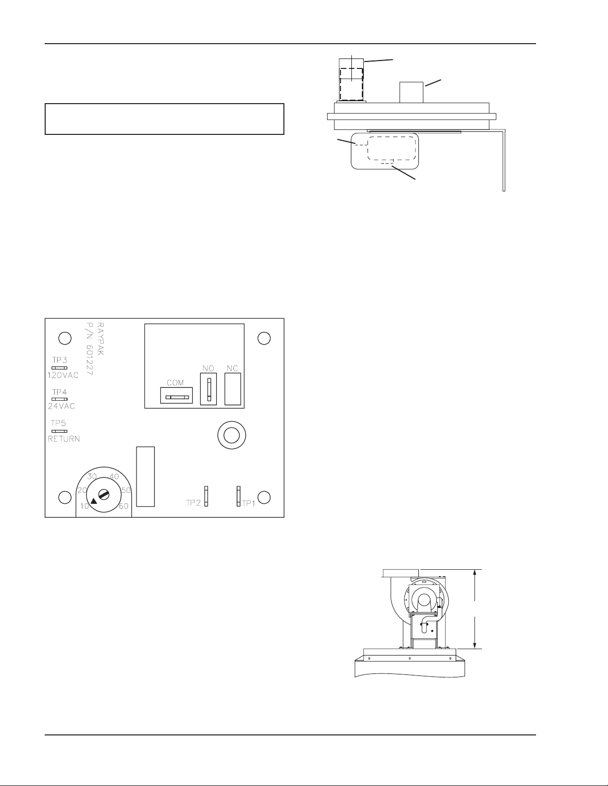
Draft-Proving Switch
The draft-proving switch ensures that the blower is
operating. The switch is in the limit circuit and does not
allow the ignition module to operate unless it is closed.
Fig. 8: Solid State Control
Negative Pressure Connector
Adjusting Screw
Normally
Open
Terminal
Common Terminal
Fig. 9: Draft Proving Switch
Positions of Discharge
Models 0514–1826 Only
A. Rotate Blower Housing 90° CW or CCW
1. Disconnect pressure tube from blower housing.
2. Remove (6) screws that mount motor to blower
housing.
3. Remove (2) rear screws that mount motor to support bracket.
4. Slide out motor.
5. Remove (2) screws that mount blower housing to
plenum collar.
6. Rotate blower housing 90° CW or CCW.
7. Reverse above procedure to re-assemble.
NOTE: Verify shaft rotation is CW when viewed
from motor end.
Fig. 10: Blower Assembly Position 1
ON
C
POSITION 1
STANDARD POSITION AS
SHIPPED FROM FACTORY
A
FRONT
RIGHT SIDE
Page 13
13
Fig. 12: Blower Assembly Position 3
B. Rotate Plenum/Blower Assembly
1. Remove (8) screws that mount plenum/blower
assembly to jacket top.
2. Rotate plenum/blower assembly from position 2 or
3 so motor is toward front side of unit.
3. Reverse step (1) to re-assemble.
Fig. 13: Blower Assembly Position 4
Fig. 14: Blower Assembly Position 5
Model No. Without Pump With Pump
0514–1336
Less than
10 amps
@ 120 VAC
Less than
16 amps
@ 120 VAC
1468–1826
Less than
18 amps
@ 120 VAC
Less than
24 amps
@ 120 VAC
Table C: Electrical Ratings—Models 0514–1826
NOTE: Vent terminal should be installed with motor
toward either the right side or front side of the heater.
FRONT
Fig. 11: Blower Assembly Position 2
POSITION 2
ROTATE BLOWER HOUSING
90° CW FROM POSITION 1
RIGHT SIDE
ROTATE PLENUM/BLOWER ASSY
POSITION 4
FROM POSITION 2 SO MOTOR
IS TOWARD FRONT SIDE OF BOILER
E
FRONT
POSITION 3
ROTATE BLOWER HOUSING
90° CCW FROM POSITION 1
F
FRONT
RIGHT SIDE
POSITION 5
ROTATE PLENUM/BLOWER ASSY
FROM POSITION 3 SO MOTOR
IS TOWARD FRONT SIDE OF BOILER
FRONT
Page 14

14
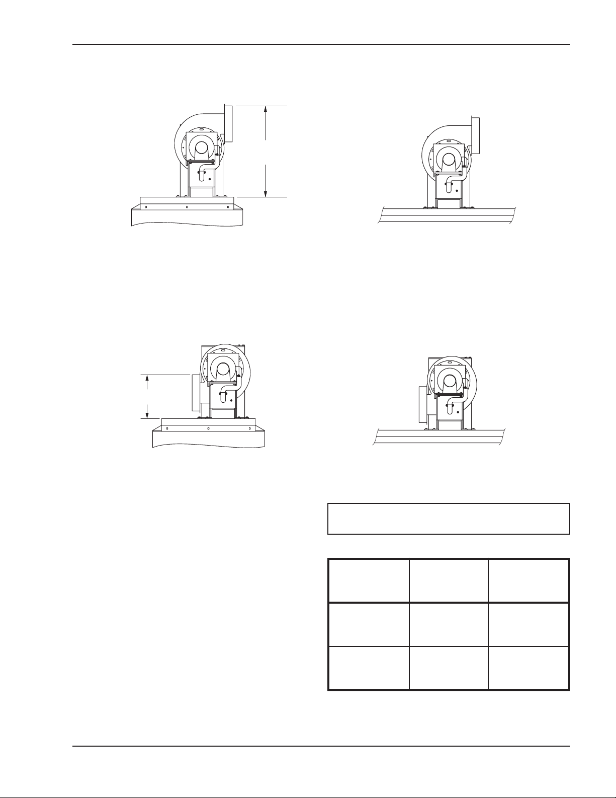
Dimensions—Models 0514–1826
Model
No.
MBTUH
Vertical
Height
(ft)
Max.
Horizontal
(ft)**
A (in.) B (in.) C (in.) D (in.) E (in.) F (in.)
0514 512 20 40 17.88 15.88 20 8* 20.25 9.75
0624 627 20 22 17.88 15.88 20 8* 20.25 9.75
0724 726 20 13 17.88 15.88 20 8* 20.25 9.75
0824 825 20 22 17.88 15.88 20 8 20.25 9.75
0962 962 20 12 19.44 15.88 20 8 21.81 11.31
1125 1125 20 5 19.44 15.88 20 8 21.81 11.31
1223 1223 20 4 19.44 15.88 20 8 21.81 11.31
1336 1336 20 21 21 18.62 42 10 23.5 12.5
1468 1468 20 15 21 18.62 42 10 23.5 12.5
1631 1631 20 10 21 18.62 42 10 23.5 12.5
1826 1826 20 5 21 18.62 42 10 23.5 12.5
Table D: Dimensions, Models 0514–1826
* May be reduced to 7" by using 8" x 7" transition. Transition is not provided by Raypak.
**Subtract 10 ft per elbow, if applicable.
D
FRONT
FRONT
RIGHT SIDE
RIGHT SIDE
A
B
FRONT
C
E
F
FRONT
RIGHT SIDE
Page 15

15
Dimensions—Models 2100–4001
Model
No.
MBTUH
Vertical
Height
(ft)
Max.
Horizontal
(ft)*
A (in.) B (in.) C (in.) D (in.) E (in.) F (in.)
2100 2100 20 60 16.88 22.38 33.5 14 17.25 7.68
2500 2499 20 60 16.88 22.38 33.5 14 21.75 12.18
3001 3000 20 60 24.25 27.38 44.75 16 23.62 10.12
3500 3500 20 60 24.25 27.38 44.75 16 29.25 15.75
4001 4000 20 60 24.25 27.38 44.75 16 34.88 21.38
Table F: Dimensions, Models 2100–4001
Model No. Without Pump With Pump
2100–2500
Less than
16 amps
@ 120 VAC
120 VAC N/A
Separate
Power Supply
Required
3001–4001
Less than
19 amps
@ 120 VAC
6.2A @
230VAC,
3.1A @
460VAC
Table E: Electrical Ratings—Models 2100–4001
*Subtract 10 ft per elbow, if applicable.
C
F
Outlet
A
Temp Control
Hi Limit Manual
Vent Switch
Fan Delay Board
and Contactor
Primary
J-Box
FRONT
E
RIGHT SIDE
B
D
TOP
Page 16

www.raypak.com
Raypak, Inc., 2151 Eastman Avenue, Oxnard, CA 93030 (805) 278-5300 Fax (805) 278-5468
Litho in U.S.A.
 Loading...