

Page 1
The Hot Water Management Experts
SM
®
Raytherm
Selection Guide
Specifications for
Commercial Atmospheric:
Hydronic Heating Boilers
ater Heaters
W
Page 2
R
EF
H
eightJacket Gas Water Flue
TO
Width Overall HeightConn.Conn.Dia.
DWG H WH InputOutput
InputOutput ABCGHJKLLess Pump W/Pump
1 133••136.0 112.0
136.0 112.0 24-1/8 45.0 30-1/8 1/2 1-1/4 6 9-1/4 145 195
1
82/181• •181.0 148.0
181.0 148.0 18-1/4 62-5/8 38 3/4 1-1/2 12-1/16 6 11-13/16 191 221
260/261• •264.0 216.0 264.0 216.0
2
2-3/8 62-7/8 38 3/4 1-1/2 11-1/8 7 13-3/8 214 244
330/331• •334.0 274.0
334.0 274.0 25-3/4 63-3/4 38 3/4 1-1/2 10-3/4 8 15-3/4 239 264
400/401• •399.0* 327.0* 399.0* 327.0*
2
9-1/4 65-3/8 38 4-Mar 1-1/2 12-1/2 9 17-3/4 253 283
5
14••511.5 419.4
511.5 419.4 32-3/4 57.0 33 1 2 10 25-3/8 455 510
624••627.0 514.0
627.0 514.0
37-1/2 57.0 33 1 2 12 29-1/2 465 520
7
24••726.0 595.0
726.0 595.0
4
1-5/8 57.0 33 1 2 12 34-1/4 575 630
824••825.0 676.5
825.0 676.5
45-3/4 57.0 33 1 2 14 38-1/2 605 660
926••
926.0 759.0
0
48587
)c( 2/1-21
8/3-25
9
62••961.7 788.6 52-3/8 76-1/8 33-1/2 1 2-1/2 (c) 23-5/8 14
2
8 705 760
1083• •
1083.0 888.0
02
9568
)c
( 2/1
-2
)b(
4/1-95
1125• •1124.7 922.0 59-1/4 78-1/8 33-1/2 (b) 2-1/2 (c) 23-5
/8 16 32 745 800
1
178• •
1178.0 966.0
089529
)
c( 2/1-2)b(
8/5-36
1223• •1222.5 1002.4 63-5/8 78-1/8 33-1/2 (b) 2-1/2 (c) 23-
5/8 16 32 805 860
1287• •
1287.0 1055.0
53
01089
)
c( 2/1-24/1
-1
8/5
-
8
6
1336• •1336.6 1096.0 68-5/8 80-1/8 33-1/2 1-1/4 2-1/2 (c) 2
3-5/8 18 36 875 930
1
414• •
1413.0 1158.5
03110801
)c( 2/1-24/1-1
8/7-47
1468• •1467.0 1203.0 74-7/8 80-1/8 33-1/2 1-1/4 2-1/2 (c) 2
3
-5/8 18 36 945 1000
1571• •
1570.0 1287.0
09
110311
)c( 2/1-24/1
-1
8/1-1
8
1
631• •1630.0 1336.6 81-1/8 83-1/8 36-1/2 1-1/4 2-1/2 (c) 2
3-5/8 18 36 985 1040
1758• •
1758.0 1441.5
02210611
)c( 2/1-24/1-
1
8/3-9
8
1826• •1825.6 1497.0 89-3/8 85-1/8 36-1/2 1-1/4 2-1/2 (c) 2
3-5/8 20 40 1035 1090
2100• •2100.0 1722.0 61.0 68-1/4 (d) 3(c) 24 1400
2500• •2499.0 2049.0 70.0 68-1/4 (d) 3(c) 26 1580
3001• •3000.0 2460.0 81-1/4 68-1/4 2 3(c) 28 1750
3500• •3500.0 2870.0 92-1/2 68-1/4 2 3(c) 30 1920
4001• •4000.0 3280.0 103-3/4 68-1/4 2 3(c) 32 2100
*2-Stage 401 (Low NOx) derated 5%.
4
INDOOR
M
BTUH NATURAL GAS (a)
T
YPES
MODEL
Approximate
O
perating Weight
LBS.
3
2
OUTDOOR
A
VAILABLE
DIMENSIONS (INCHES)
5
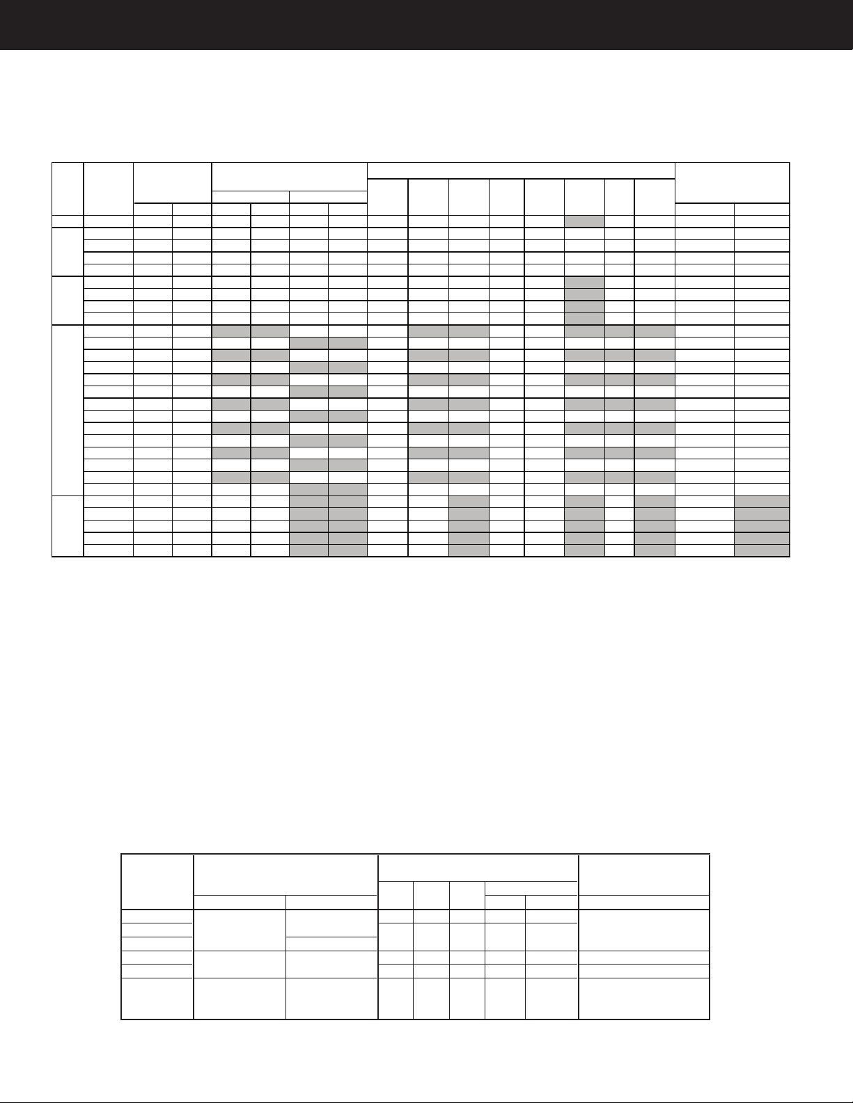
Specifications and Dimensions
Models
Left Right To
p
With Pump Without Pump Rear Side Side Indoor Outdoor
Multiplier
133
Less than
Less than 12" 12" 6" 42" Unobstr.
182 - 400
10 amps @ 120V
1 amp @ 120V
181 - 401 5 amps @ 120V
514 - 824 Less than Less than 12" 18" 6" 36" Unobstr.
0.94
926-1826 10 amps @ 120V 4 amp @ 120V 24" 24" 24" 24" Unobstr.
0.92 Indoor/0.955 Outdoor
951276 pump* Less than
2100 - 4001 11 amps @ 230V 8 amps @ 120V
22 amps @ 110 V
Unobstr.12"
MIN CLEARANCES TO COMBUSTIBLE
CONSTRUCTION
12" 12"
1.0 (Same as natural gas)
PROPANE GASELECTRICAL RATINGS
24" 24" 24" 24" N/A
1.0 (Same as natural gas)
39"
The Raytherm Selection Guide is a ready-reference to Raypak’s full line of atmospheric commercial
hydronic heating boilers, water heaters and packaged systems. The user, the specifier and the
installer will find nearly all the significant information they require to select the proper Raytherm
boiler, water heater, or package system for their particular need or application.
Hydronic Hot Water Supply
H1 Mechanical modulation, high temp WH1 On/Off
H2 Motorized modulation WH2 Mechanical modulation (133-1826)
H3 2-Stage WH2 Motorized modulation (2100-4001)
H4 On/Off WH3 2-Stage
H5 Mechanical modulation, low-temp WH9 4-Stage
H9 4-Stage
Note:
Ratings shown are for elevations up to 2000 feet. Elevations over 2000 feet ratings should be reduced at the rate of 4% for each
1000 feet above sea level.
(a) For Propane, see MBTUH Propane Gas chart below
(b) 1” or -1/14” gas connection contingent on boiler type & code requirements
(c) 3” NPT on Single Pass Option for Model H 926 - 1826
(d) 1-1/2” or 2” gas connection contingent on boiler type & code requirements
4” Copper tubing on Single Pass Option for Model H 2100 - 4001
*Pump requires separate power supply
Page 2
Page 3
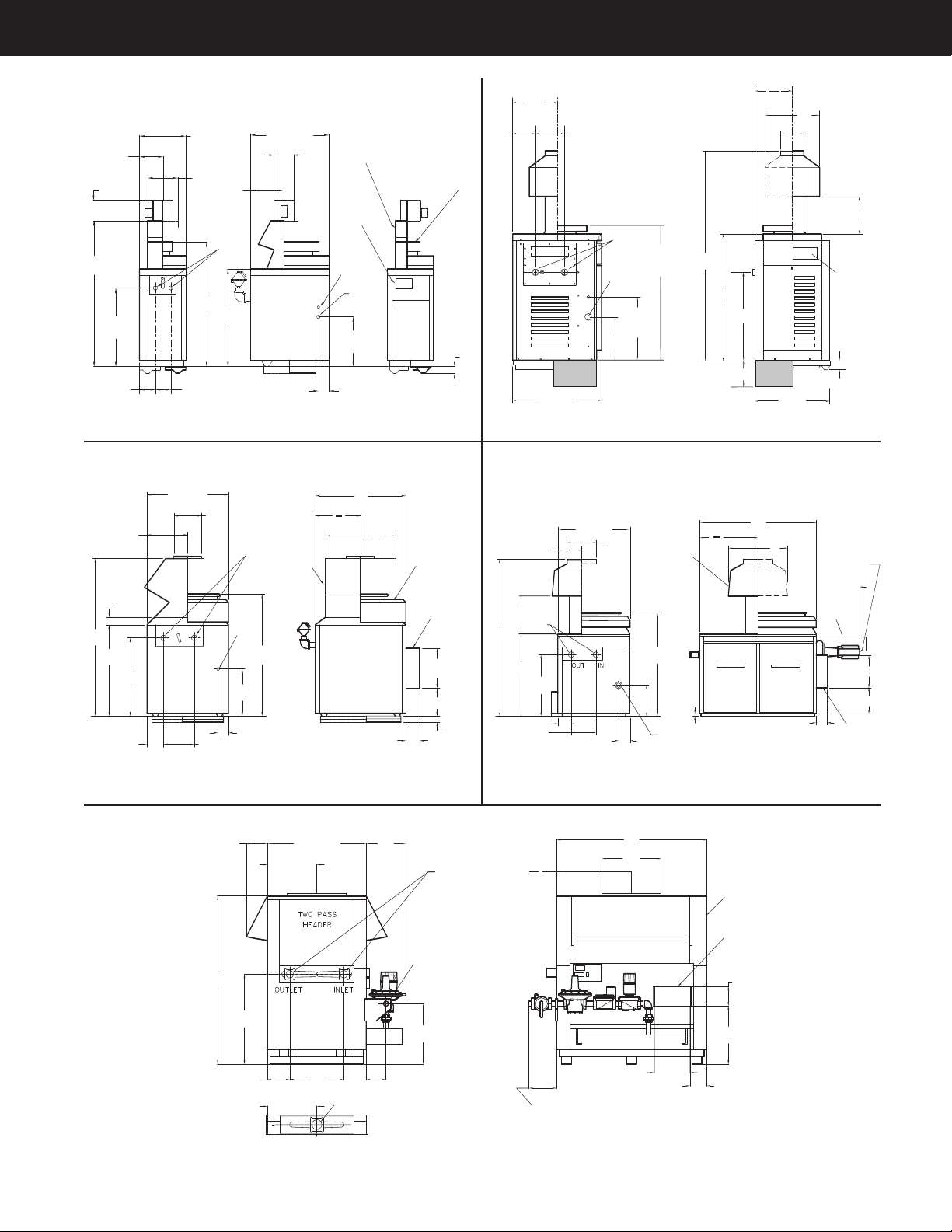
Drawing 1 Drawing 2
Drawing 3 Drawing 4
Drawing 5
H
38-1/2
B
24-1/2
6-1/4
7-1/4
14-1/4
L
R
EAR
V
IEW
C
A
K
10-1/4
ELEC
CONN
G
G
AS
15-3/8
3-1/4
F
RONT
V
IEW
C
OMBUSTIBLE
F
LOOR SHIELD
(
OPTIONAL)
2
I
NDOOR
DRAFT
D
IVERTER
OUTDOOR
S
TACKLESS
UP
FRONT
CONTROLS
4-7/8
11-1/8
O
UT
I
N
OUT IN
OUT
IN
C
G
G
AS
B
OUTDOOR
BASE
A
8
J
K
L
A
2
26-1/2
21-1/4
ELEC
CONN
H
U
P
F
RONT
CONTROLS
40
S
TACKLESS
OUTDOOR TOP
13-1/4
8-1/2
11
6-3/4
26-1/2
2-1/2
OPTIONAL
COMBUSTIBLE
FLOOR SHIELD
29-1/2
14-3/4
K
H
44-1/8
G
GAS
17
3-3/4
11-1/86
28-1/4
B
C
2-3/4
A
A
2
L
OUTDOOR
STACKLESS
TOP
I
NDOOR
DRAFT
DIVERTER
ELEC
C
ONN
14-1/2
10
2-1/4
5
COMBUSTIBLE
FLOOR SHIELD
(OPTIONAL)
1-5/8
H
27-3/4
6
11-1/8
5-1/8
G
GAS
1
4
46-3/4
19-1/2
PUMP
COVER
(OPTIONAL)
PUMP
(OPTIONAL)
14-1/2
11-3/4
ELEC
CONN
5
C
OMBUSTIBLE
F
LOOR
S
HIELD
(OPTIONAL)
I
NDOOR
D
RAFT
H
OOD
A
A
2
L
32-1/2
K
11-1/4
B
J
C
H
G
GAS
24-1/2
8
22
9-1/8
16
40-1/4
20-1/8
8-1/2
B
36-1/2
H-OUTLET
20-1/8
OPTIONAL ONE PASS
14-1/2
6-3/4
DIMENSION VARIES BY MODEL AND
TYPE CONSULT FACTORY FOR DETAILS.
A
K
A
2
BUILT-IN
DRAFT
DIVERTER
ELEC
CONN
8
23-5/8
Dimensional Drawings
Page 3
Page 4

H Features
FEATURES 181- 514- 926- 2100- 3001-
133 401 824 1826 2500 4001
ASME Inspected and Stamped – 160 psi • • • • • •
National Board ••••••
reppoC –sebuT regnahcxE taeH ••••••
– Cupro Nickel 0 0 0 0 0
norI tsaC –sredaeH ••••••
– Bronze 0 0 0 0 0
000ssaP-elgniS – norI tsaC –
isp 03 – evlaV feileR erusserP 000000
)a(000••isp 54 –
••••00isp 06 –
000000isp 57 –
– 125 psi 000000
– 150 psi 000000
Temperature & Pressure Gauge ••••••
esahP elgniS –V021 - pmuP 0000
Bolted Cabinet •••••
roodnI –epyT kcatS –sretreviD tfarD ••••
– Low Profile – Outdoor ••••
– Built-in – Indoor ••
•••roodtuO/roodnI – elbaegnahcretnI dleiF –
Enclosed Controls (b) ••••
Combustible Floor Shield 0000
Power Supply, 120V ••••••
Transformer 120V/24V ••••••
On/Off Switch ••••••
Economaster II Pump Time Delay – 120V 10A Max. • • • • • •
5H 1HsevlaV gnitaludoM .hceM –lortnoC erutarepmeT ••••
••002HF°042-061– rellortnoC doM .rotoM –
9H 3HrellortnoC degatS – 000000
4HrellortnoC ffO/nO – 000000
ytefaS toliP %001 ,V42 –draugefaS emalF ••••••
tuokcoL /W .ngI toliP tnettimretnI ,cinortcelE – toliP ••••••
High Gas Pressure Switch (c) 0000•
Low Gas Pressure Switch (c) 00000
Low Water Cut-off 00000
elbatsujdA –teseR launaM –hctiwS timiL hgiH •••••
– Automatic Reset – Adjustable 0 0 0 0 •
0F°042 dexiF –teseR citamotuA –
Flow Switch •••••
Gas Pressure Regulator ••••••
Manual Gas Valve - Main Gas Shut-Off ("A" valve) • • • • • •
5H 1HlacinahceM –gnitaludoM –evlaV lortnoC ••••
– Modulating – Motorized H2 H6 ••••
– Staged – Diaphragm H3 H9 • • • •
•9H 3HdezirotoM –degatS –
– On/Off – Diaphragm H4 • • • •
•4HdezirotoM – ffO/nO –
Leak Test Ports ••••
mgarhpaiD –)tnadnudeR( evlaV ytefaS •••••
– Motorized 0 0 0 0 •
Right-Hand Water Connections 00000
Power Vent 000000
CSD-1 Code (d) (d) (d) (d)
Factory Mutual Insurers Control System (FM) 0
Diagnostic Alarm System 00000
6HmetsyS tnemeganaM relioB 0006B 0000
)5-B( oitaR .tsujdA-noN - doM .rotoM –lortnoC teseR roodtuO 0000
– Stage (B-4 and Y-2 series) 00000
GAS TRAIN SAFETY CONTROLS
OPER. CTRLS.
OPTIONS
H MODELS
HEAT EXCHANGERJACKET
ELECT.
TYPE H – Hydronic heating boiler. Used on closed loop for space heating systems
(a) 45 PSI PRV not available on models 3500 or 4001.
(b) On certain applications, controls may be mounted on
other than the front of the boiler.
(c) Required as part of certain code-compliant
configurations.
(d) Parts added vary with firing mode.
Page 4
• = Standard item
0 = Optional item
= Not Applicable
Page 5

FEATURES 181- 514- 926-
2100-
3001-
133 401 824 1826 2500 4001
ASME Inspected and Stamped – 160 psi • • • • • •
National Board • • • • • •
Heat Exchanger Tubes– Copper • • • • • •
–
Cupro Nickel 0 0 0 0 0
e
znorB –sredaeH • • • • • •
– Cast Iron 0 0 0 0 0
– Cast Iron – Single-Pass 0 0 0
Pressure Relief Valve – 125 psi • • • • • •
– 150 psi 0 0 0 0 0 0
T
emperature & Pressure Gauge • • • • • •
e
sahP elgniS –V021 - pmuP 0 0 0 0
Bolted Cabinet • • • • •
roodnI –epyT kcatS –sretreviD tfarD • • • •
– Low Profile – Outdoor • • • •
– Built-in – Indoor ••
•••roodtuO/roodnI – elbaegnahcretnI dleiF –
Enclosed Controls (a) • • • •
Combustible Floor Shield 0 0 0 0
Power Supply, 120V • • • • • •
Transformer 120V/24V • • • • • •
On/Off Switch • • • • • •
Economaster II Pump Time Delay – 120V 10A Max. • • • • • •
0000001HWrellortnoC ffO/nO –lortnoC erutarepmeT
– Mech. Modulating Valves –110-170°F W H 2 • • • •
– Motor. Mod Controller –104-220°F W H 2 0 0
0000003HWrellortnoC degatS –
Flame Safeguard – 24V , 100% Pilot Safety • • • • • •
coL /W .ngI toliP tnettimretnI ,cinortcelE – toliP ••••••tuok
High Gas Pressure Switch (b) 0 0 0 0•
Low Gas Pressure Switch (b) 0 0 0 0 0
Low Water Cut-Off 0 0 0 0 0
High Limit Switch – Manual Reset – Adjustable • • • • •
– Automatic Reset – Adjustable 0 0 0 0•
•F°002 dexiF –teseR citamotuA –
Flow Switch • • • • •
Gas Pressure Regulator • • • • • •
Manual Gas Valve - Main Gas Shut-Off ("A" valve) • • • • • •
•••••1HWmgarhpaiD –ffO/nO –evlaV lortnoC
– On/Off – Motorized WH1 •
– Modulating – Motorized WH2 • •
– Modulating – Mechanical WH2 • • • •
– Staged– DiaphragmWH3 • • • •
– Staged – Motorized WH3 •
•••••mgarhpaiD –)tnadnudeR( evlaV ytefaS
– Motorized 0 0 0 0•
Right-Hand Water Connections 0 0 0 0 0
Power Vent 0 0 0 0 0 0
CSD-1 Code (c) (c) (c) (c)
Factory Mutual Insurers Control System (FM) 0
Diagnostic Alarm System 0 0 0 0 0
OPTIONS GAS TRAIN SAFETY CONTROLS
OPER. CTRLS.
WH MODELS
HEAT EXCHANGER
JACKET
ELECT.
WH Features
TYPE WH – Direct-fired hot water supply for use with storage tank
(a) On certain applications, controls may be
mounted on other than the front of the boiler.
(b) Required as part of certain code-compliant
configurations.
(c) Optional, but water heaters are normally
• = Standard item
0 = Optional item
= Not Applicable
exempted from this code. See section CG-130.
Page 5
Page 6

Flow Rates and Pressure Drops
GPM ∆T ∆P FT GPM ∆T ∆P FT GPM ∆P FT GPM ∆P FT GPM ∆P FT GPM ∆P FT
133* 23 10 16.3 10 23 3.3 23 16.3 11 3.9
181/182 45 7 9.2 20 15 1.8 30 4.2
260/261 45 10 9.4 20 22 1.9 44 8.8 22 2.2
330/331 45 12 9.6 20 28 1.9 28 3.7
400/401 45 15 9.8 20 33 2.0 33 5.2 22 2.3
514 90 9 9 40 21 1.8 84 7.8 42 1.9
624 90 12 9.5 40 26 1.9 52 3.0
724 90 13 10 40 30 2.0 60 4.4 40 2.0
824 90 15 10.5 40 34 2.1 68 6.0 46 2.8
926 90 17 11 40 38 2.2 77 8.0 51 3.5
962 90 18 11 40 40 2.2 80 8.8 53 3.8
1083 90 20 12 45 40 3.1 90 12.0 60 5.3 45 3.1
1125 90 21 12 47 40 3.3 90 12.0 62 5.6 47 3.3
1178 90 22 12.5 49 40 3.8 65 6.5 49 3.8
1223 90 22 12.5 51 40 4.0 68 7.1 51 4.0
1287 90 24 13.2 53 40 4.5 71 8.2 53 4.5
1336 90 25 13.2 55 40 4.9 74 8.9 55 4.9
1414 90 26 14 58 40 5.8 78 10.5 58 5.8
1468 90 27 14 61 40 6.4 81 11.3 61 6.4
1571 90 29 14.5 65 40 7.5 87 13.5 65 7.5
1631 90 30 14.5 68 40 8.3 90 14.5 68 8.3
1758 90 32 15.4 73 40 10.0 73 10.0
1826 90 34 15.4 76 40 10.8 76 10.8
2100 200 17 14.8 90 38 3.2 174 11.2 116 5.1
2500 200 21 15.8 103 40 4.4 138 7.8 103 4.4
3001 200 25 16.7 124 40 6.7 166 11.6 124 6.7
3500 200 29 17.5 145 40 9.5 191 16.2 145 9.5
4001 200 33 18.7 166 40 13.0 166 13.0
926 200 8 9.7 90 17 2.1 152 5.7
962 200 8 9.7 90 18 2.1 157 6.1
1083 200 9 10.3 90 20 2.3 178 8.2
1125 200 9 10.3 90 20 2.3 184 8.8 92 2.3
1178 200 10 11 90 21 2.4 193 10.3 97 2.7
1223 200 10 11 90 22 2.4 200 11.0 100 2.9
1287 200 11 11.7 90 23 2.5 106 3.4
1336 200 11 11.7 90 24 2.5 110 3.7
1414 200 12 12.2 90 26 2.7 116 4.2
1468 200 12 12.2 90 27 2.7 120 4.5
1571 200 13 13 90 29 2.8 129 5.5
1631 200 13 13 90 30 2.8 134 6.0
1758 200 14 14.7 90 32 3.0 144 7.3 96 3.4
1826 200 15 14.7 90 33 3.0 150 8.0 100 3.7
2100 400 9 18 180 19 4.0 344 14
2500 400 10 18.8 180 23 4.1 205 5.3
3001 400 12 19.5 180 27 4.3 246 7.8
3500 400 14 20.5 180 32 4.5 287 11.0 191 5.0
4001 400 16 21.5 180 36 4.7 328 14.8 219 6.8
10°F ∆T 20°F ∆T 30°F ∆T
Exceeds maximum flow,
2**
TWO-PASSSINGLE-PASS
1
See chart #
Model
Size
MAX FLOW / MIN ∆T MIN FLOW / MAX ∆T
CHART 1 CHART 2
MAXIMUM & MINIMUM FLOW RATES PRESSURE DROPS
1
Less than minimum flow,
See chart #
2**
2**
1
1
40°F ∆T
* 4-pass heater
** Minimum flow rates in closed systems may be reduced to a flow rate consistent with a 40°F ∆T.
Maximum flow rates limited by maximum acceptable velocity through the heat exchanger tubes. May be increased
by 10% for closed heating systems. Pressure drop would increase 21%. Single pass heat exchangers are to be
used only when flow rates exceed the allowable for two pass.
Use single-pass when flow rates exceed the maximum allowable for 2-pass.
Recommend maximum 35°F rise for domestic hot water.
Page 6
Page 7

Model Input
10F° 20F° 30F° 40F° 50F° 60F° 70F° 80F° 90F° 100F° 110F° 120F° 130F° 140F° 150F°
Number MBTU
133 136 1352 676 451 338 270 225 193 169 150 135 123 113 104 97 90
182/181 181 1799 900 600 450 360 300 257 225 200 180 164 150 138 129 120
260/261 264 2624 1312 875 656 525 437 375 328 292 262 239 219 202 187 175
330/331 334 3320 1660 1107 830 664 553 474 415 369 332 302 277 255 237 221
400/401 399 3966 1983 1322 991 793 661 567 496 441 397 361 330 305 283 264
514 511.5 5084 2542 1695 1271 1017 847 726 636 565 508 462 424 391 363 339
624 627 6232 3116 2077 1558 1246 1039 890 779 692 623 567 519 479 445 415
724 726 7216 3608 2405 1804 1443 1203 1031 902 802 722 656 601 555 515 481
824 825 8200 4100 2733 2050 1640 1367 1171 1025 911 820 745 683 631 586 547
962 961.7 9559 4779 3186 2390 1912 1593 1366 1195 1062 956 869 797 735 683 637
1125 1124.7 11179 5589 3726 2795 2236 1863 1597 1397 1242 1118 1016 932 860 798 745
1223 1222.5 12151 6075 4050 3038 2430 2025 1736 1519 1350 1215 1105 1013 935 868 810
1336 1336.6 13285 6642 4428 3321 2657 2214 1898 1661 1476 1328 1208 1107 1022 949 886
1468 1467 14581 7291 4860 3645 2916 2430 2083 1823 1620 1458 1326 1215 1122 1042 972
1631 1630 16201 8101 5400 4050 3240 2700 2314 2025 1800 1620 1473 1350 1246 1157 1080
1826 1825.6 18145 9073 6048 4536 3629 3024 2592 2268 2016 1815 1650 1512 1396 1296 1210
2100 2100 20873 10436 6958 5218 4175 3479 2982 2609 2319 2087 1898 1739 1606 1491 1392
2500 2499 24839 12419 8280 6210 4968 4140 3548 3105 2760 2484 2258 2070 1911 1774 1656
3001 3000 29818 14909 9939 7455 5964 4970 4260 3727 3313 2982 2711 2485 2294 2130 1988
3500 3500 34788 17394 11596 8697 6958 5798 4970 4348 3865 3479 3163 2899 2676 2485 2319
4001 4000 39758 19879 13253 9939 7952 6626 5680 4970 4418 3976 3614 3313 3058 2840 2651
133 136 1352 676 451 338 270 225 193 169 147 135 123 113 104 97 90
182/181 181 1799 900 600 450 360 300 257 225 195 180 164 150 138 129 120
260/261 264 2624 1312 875 656 525 437 375 328 284 262 239 219 202 187 175
330/331 334 3320 1660 1107 830 664 553 474 415 360 332 302 277 255 237 221
400/401 399 3966 1983 1322 991 793 661 567 496 430 397 361 330 305 283 264
514 511.5 5084 2542 1695 1271 1017 847 726 636 565 508 462 424 391 363 339
624 627 6232 3116 2077 1558 1246 1039 890 779 692 623 567 519 479 445 415
724 726 7216 3608 2405 1804 1443 1203 1031 902 802 722 656 601 555 515 481
824 825 8200 4100 2733 2050 1640 1367 1171 1025 911 820 745 683 631 586 547
926 926 9204 4602 3068 2301 1841 1534 1315 1150 1023 920 837 767 708 657 614
1083 1083 10764 5382 3588 2691 2153 1794 1538 1346 1196 1076 979 897 828 769 718
1178 1178 11709 5854 3903 2927 2342 1951 1673 1464 1301 1171 1064 976 901 836 781
1287 1287 12792 6396 4264 3198 2558 2132 1827 1599 1421 1279 1163 1066 984 914 853
1414 1413 14044 7022 4681 3511 2809 2341 2006 1756 1560 1404 1277 1170 1080 1003 936
1571 1570 15605 7802 5202 3901 3121 2601 2229 1951 1734 1560 1419 1300 1200 1115 1040
1758 1758 17473 8737 5824 4368 3495 2912 2496 2184 1941 1747 1588 1456 1344 1248 1165
Outdoor Models
Indoor Models
Gallons per Hour (GPH)
Recovery Rates
Temperature Rise
Recovery Rates
Page 7
For gallons per minute (GPM) divide GPH by 60
Page 8

Storage Tanks
Y
TICAPAC
SNOLLAG
ABCDEFHJ
X
ORPPA
G
NIPPIHS
.SBL.TW
EDOCNON
0
8 TPN"28/5-8561/7-4261/3-0261/3-3161/3-6358/5-3391
511 TPN"24/1-954/1-8261/1-8161/1-1161/3-4358/5-3633
EDOCEMSA
08 TPN"28/5-8561/7-4261/3-0261/3-3161/3-6358/5-3552
511 TPN"24/1-954/1-8261/1-8161/1-1161/3-4358/5-3583
571 TPN"2/1-24/1-764/1-2361/9-9161/9-2161/9-5853695
80- to 175-GALLON TANKS
ASME CODE AND NON-CODE
Features
• 150 PSI maximum working pressure • Foam insulation
• Two magnesium anodes • Labels for each opening
• Handhole (175-gallon only) • R-16 value insulation
• Large drain valve provided • Meets ASHRAE 90A
(80- and 115-gallon only) • Insulated and jacketed
For more information, see catalog 4000.20.1 and 4000.21.
* Note: 175 gallon tank drain conn 1” NPT w/o valve.
175 gallon tank tankstat connection located above drain
connection at height indicated above.
235- to 2,590-GALLON TANKS
ASME CODE
Stock Custom Tanks
• Sizes from 235 to 534 Gallons
• 125 PSI ASME
• Vertical only
• Handhole (4” x 6”)
• Angle iron legs
• Glass lining
• Threaded openings:
2-1/2” NPT supply, return and outlet
1” NPT T&P relief valve
1” NPT drain
• Insulation and jacketing available
Custom Tanks
• Sizes up to 2,590 Gallons
• 125 PSI standard
• 150 PSI available 36” thru 72” diameters
• Glass, epoxy or cement lining
• Vertical and horizontal
• Anodes standard on glass-lined tanks
• Manhole standard
• Insulation and jacketing available
• Larger tanks available upon request
ISO 9001
The Hot Water Management Experts
SM
2151 Eastman Avenue, Oxnard CA, 93030
(805) 278-5300 Fax (800) 872-9725
www.raypak.com
For more information, see
catalog 4000.10
Raypak, Inc. reserves the right to make product changes or improvements at any time without notice.
PART
VOL
NUMBER
GALBDIACO.A. HT
951408 235 30.0 84.0 10.31 15.75 7.88 30” 3 30 548
951409 335 36.0 84.0 12.00 18.88 9.44 30” 3 28.5 658
951410 534 42.0 96.0 12.25 24.92 16.5 45” 4 33 991
F G H J K M
Catalog Number: 1100.10T
SHIPPING
WEIGHT (LBS.)
Effective: 7-15-10
Replaces: 2-01-07
 Loading...