

Page 1
INSTALLATION & OPERATING
INSTRUCTIONS
Models 300, 500 & 850
Types H & W
WARNING: Improper installation, adjustment, alteration, service or maintenance can
cause property damage, personal injury, exposure to hazardous materials* or loss of
life. Review the information in this manual carefully. *This unit contains materials that
have been identified as carcinogenic, or possibly carcinogenic, to humans.
FOR YOUR SAFETY: Do not store or use gasoline or other flammable vapors and
liquids or other combustible materials in the vicinity of this or any other appliance. To
do so may result in an explosion or fire.
WHAT TO DO IF YOU SMELL GAS:
• Do not try to light any appliance.
• Do not touch any electrical switch; do not use any phone in your building.
• Immediately call your gas supplier from a neighbor's phone. Follow the gas
supplier's instructions.
• If you cannot reach your gas supplier, call the fire department.
Installation and service must be performed by a qualified installer, service agency or
the gas supplier.
This manual should be maintained in legible condition and kept adjacent to the heater or in a safe place for future
reference.
Catalog No. 1000.65 Effective: 10-16-09 Replaces: NEW P/N 241366 Rev. 1
Page 2

2
Page 3

CONTENTS
WARNINGS 4
Pay Attention to These Terms 4
BEFORE INSTALLATION 5
Product Receipt 5
Model Identification 5
Ratings and Certifications 5
Installations at Elevation 5
Component Locations 6
General Information 6
Time/Temperature Relationships
in Scalds 7
GENERAL SAFETY 7
INSTALLATION 8
Installation Codes 8
Equipment Base 8
Clearances 8
Combustion and Ventilation Air 9
Conventional Combustion Air Supply 11
Water Piping 12
Hydronic Heating 13
Gas Supply 16
Electrical Power Connections 17
Field Wiring Connection 19
Venting 23
Venting Installation Tips 25
Venting Configurations 25
Outdoor Installation 31
Controls 32
Operating Instructions 35
WIRING DIAGRAM 40
START-UP 41
Pre Start-up 41
Pre Start-up Check 41
Initial Start-up 41
Preparation 42
Start-Up 42
OPERATION 44
Lighting Instructions 44
To Turn Off Gas to Appliance 45
XFyre Error Codes 45
Heater Errors 45
Heater Faults 45
TROUBLESHOOTING 45
XFyre Fault Text 46
Sensor Resistance Values 48
MAINTENANCE 49
Suggested Minimum
Maintenance Schedule 49
Preventive Maintenance
Schedule 49
APPENDIX 52
Inside Air Contamination 52
Important Instructions for the
Commonwealth of Massachusetts 53
WARRANTY 54
START-UP CHECKLIST 55
3
Page 4
WARNINGS
Pay Attention to These Terms
ndicates the presence of immediate hazards which will cause severe
DANGER:
I
personal injury, death or substantial property damage if ignored.
WARNING:
CAUTION:
NOTE:
DANGER: Make sure the gas on which the boiler
will operate is the same type as that specified on the
boiler rating plate.
WARNING: Should overheating occur or the gas
supply valve fail to shut, do not turn off or disconnect
the electrical supply to the boiler. Instead, shut off
the gas supply at a location external to the boiler.
WARNING: Do not use this boiler if any part has
been under water. Immediately call a qualified
service technician to inspect the boiler and to
replace any part of the control system and any gas
control which has been under water.
Indicates the presence of hazards or unsafe practices which could cause
severe personal injury, death or substantial property damage if ignored.
Indicates the presence of hazards or unsafe practices which could cause
minor personal injury or product or property damage if ignored.
Indicates special instructions on installation, operation, or maintenance which
are important but not related to personal injury hazards.
WARNING - CALIFORNIA PROPOSITION
65: This product contains chemicals known to the
State of California to cause cancer, birth defects or
other reproductive harm.
CAUTION: If this boiler is to be installed above
radiation level, it must be provided with a low water
cut-off device at the time of boiler installation.
CAUTION: This boiler requires forced water
circulation when the burner is operating. See
minimum and maximum flow rates. Severe damage
will occur if the boiler is operated without proper
water flow circulation.
WARNING: To minimize the possibility of improper
operation, serious personal injury, fire, or damage to
the boiler:
• Always keep the area around the boiler free of
combustible materials, gasoline, and other
flammable liquids and vapors.
• Boiler should never be covered or have any
blockage to the flow of fresh air to the boiler.
WARNING: Risk of electrical shock. More than one
disconnect switch may be required to de-energize
the equipment before servicing.
CAUTION: If this boiler is to be installed in a
negative or positive pressure equipment room, there
are special installation requirements. Consult factory
for details.
NOTE: Minimum 18 AWG, 105°C, stranded wire
must be used for all low voltage (less than 30 volts)
external connections to the unit. Solid conductors
should not be used because they can cause
excessive tension on contact points. Install conduit
as appropriate. All high voltage wires must be the
same size (105°C, stranded wire) as the ones on the
unit or larger.
4
Page 5

BEFORE INSTALLATION
Model Identification
Raypak strongly recommends that this manual be reviewed thoroughly before installing your XFyre heater.
Please review the General Safety information before
installing the heater. Factory warranty does not apply
to heaters that have been improperly installed or operated. (Refer to the warranty at the back of this
manual.) Installation and service must be performed
by a qualified installer, service agency or gas supplier.
If, after reviewing this manual, you still have questions
which this manual does not answer, please contact
your local Raypak representative or visit our website at
www.raypak.com.
Thank you for purchasing a Raypak product. We hope
you will be satisfied with the high quality and durability
of our equipment.
Product Receipt
WARNING: Pump motors should NOT be
supported by any type of stand or support from
above due to possible misalignment of pump and
motor which may occur.
On receipt of your heater it is suggested that you visually check for external damage to the shipping crate. If
the crate is damaged, make a note to that effect on the
Bill of Lading when signing for the shipment. Next,
remove the heater from the shipping packaging.
Report any damage to the carrier immediately.
The model identification number and heater serial
umber are found on the heater rating plate located on
n
the upper rear jacket panel of the heater. The model
umber will have the form H7-850 or similar depend-
n
ing on the heater size and configuration. The letter(s)
in the first group of characters identifies the application
(H = Hydronic Heating, W = Hot Water). The number
which follows identifies the firing mode (7 = electronic
modulation). The second group of characters identifies
the size of the heater (three numbers representing the
approximate MBTUH input), and, where applicable, a
letter, indicating the manufacturing series.
Ratings and Certifications
Standards:
• ANSI Z21.13 · CSA 4.9 - latest edition, Gas-Fired
Hot Water Boilers
• CAN 3.1 - latest edition, Industrial and
Commercial Gas-Fired Package Boilers
• SCAQMD Rule 1146.2
All Raypak heaters are National Board Registered,
and design-certified and tested by the Canadian
Standards Association (CSA) for the U.S. and Canada.
Each heater is constructed in accordance with Section
IV of the American Society of Mechanical Engineers
(ASME) Heater Pressure Vessel Code and bears the
ASME “H” stamp. This heater also complies with the
latest edition of the ASHRAE 90.1 Standard.
On occasion, items are shipped loose. Be sure that
you receive the correct number of packages as indicated on the Bill of Lading.
Claims for shortages and damages must be filed with
the carrier by consignee. Permission to return goods
must be received from the factory prior to shipping.
Goods returned to the factory without an authorized
Returned Goods Receipt number will not be accepted.
All returned goods are subject to a restocking charge.
When ordering parts, you must specify the model and
serial number of the heater. When ordering under warranty conditions, you must also specify the date of
installation.
Purchased parts are subject to replacement only
under the manufacturer’s warranty. Debits for defective replacement parts will not be accepted. Parts will
be replaced in kind only per Raypak’s standard warranties.
WARNING: Altering any Raypak pressure vessel
by installing replacement heat exchangers or any
ASME parts not manufactured and/or approved by
Raypak will instantly void the ASME and CSA ratings
of the vessel and any Raypak warranty on the
vessel. Altering the ASME or CSA ratings of the
vessel also violates national, state, and local
approval codes.
Installations at Elevation
Rated inputs are suitable for up to 2000 ft elevation
without de-rating. Consult your local representative or
the factory for installations at altitudes over 2000 ft
above sea level. No hardware changes are required to
the heaters for installations up to 10,000 ft (adjustments may be required).
5
Page 6
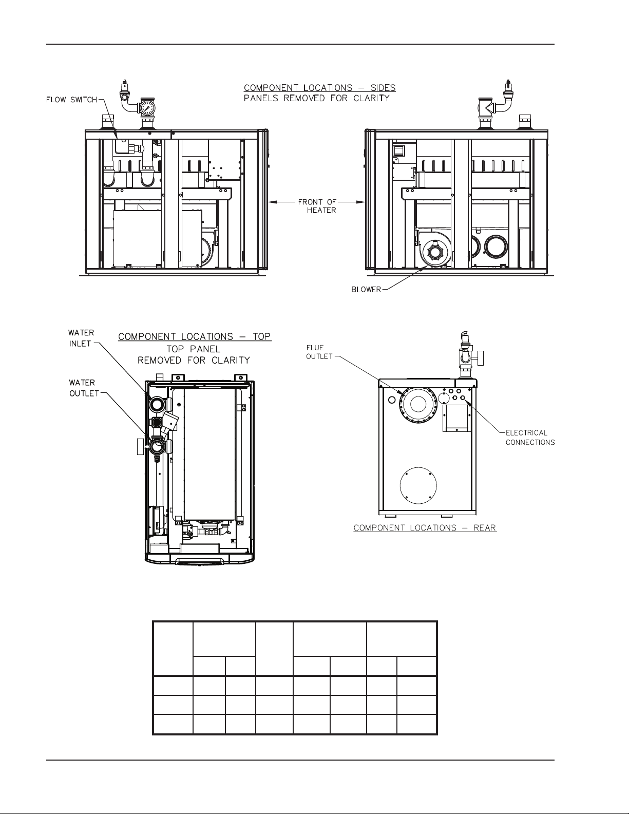
Component Locations
Model 300 shown. Component locations may vary slightly in larger models.
Fig. 1: Component Locations — Sides
Fig. 2: Component Locations — Top
General Information
Model
No.
300 300 60 1-1/2” 3/4” 3/4” 4 4
500 500 100 2” 1” 1” 4 4
850 850 170 2” 1-1/4” 1-1/4” 6 6
Fig. 3: Component Locations — Rear
MBTUH
Input
Max. Min. N P Flue Intake
Water
conn.
(NPT)
Table A: Basic Data
Gas conn.
(NPT)
6
Vent Size
(inches)
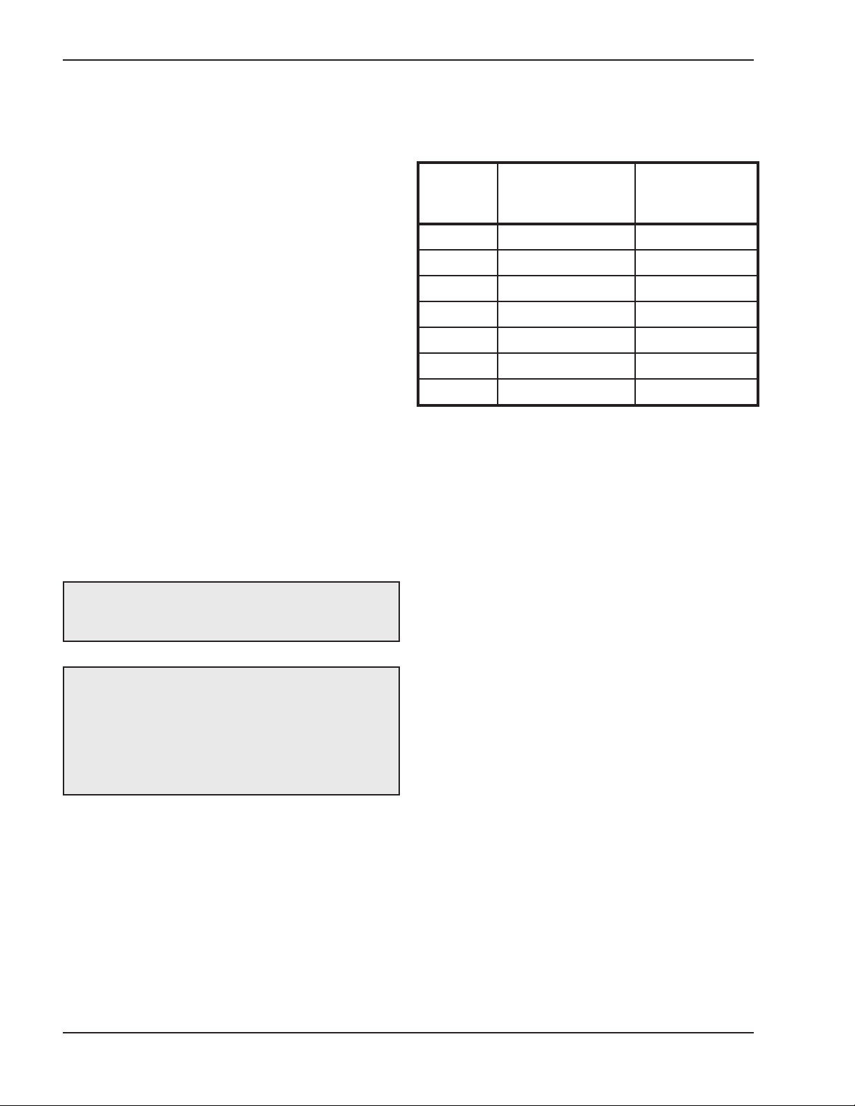
Page 7
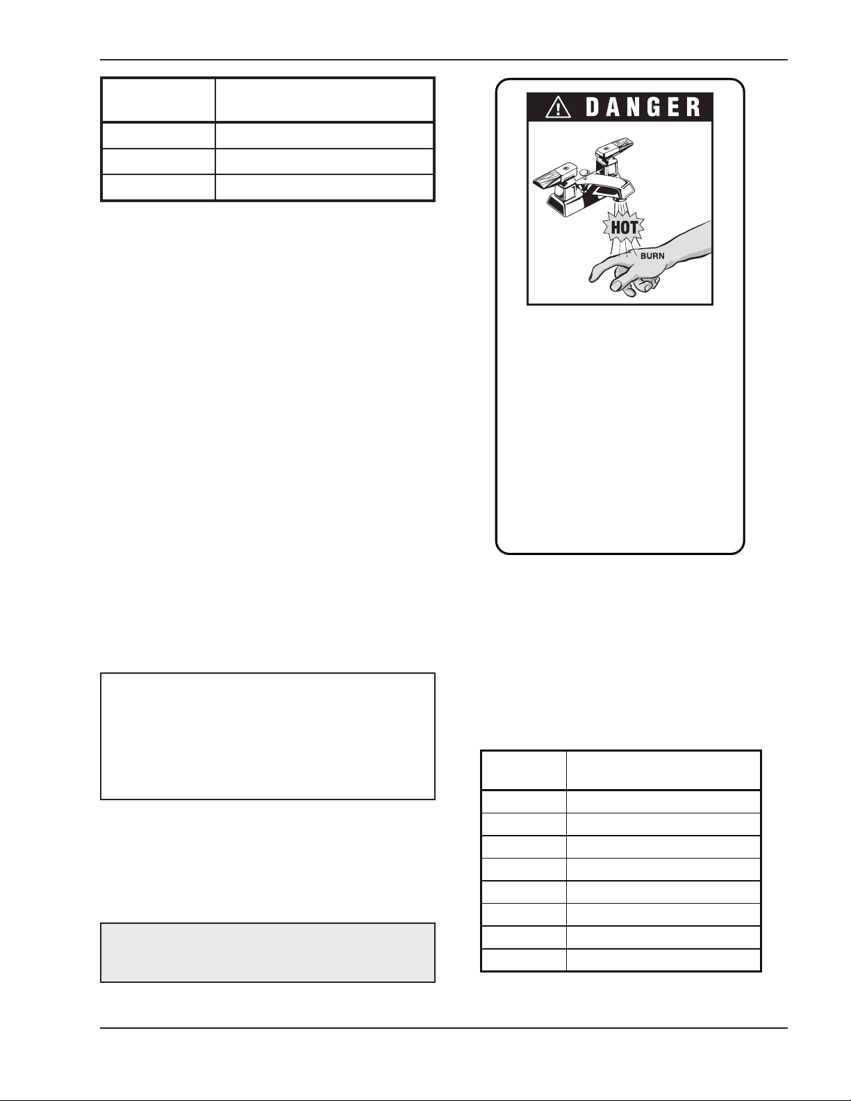
Water temperature over 125°F can
cause instant severe burns or death
from scalds.
Children, disabled, and elderly are
at highest risk of being scalded.
See instruction manual before setting temperature at water heater.
Feel water before bathing or showering.
Temperature limiting valves are
available, see manual.
Water
Temp.
Time to Produce Serious
Burn
120°F More than 5 minutes
125°F 1-1/2 to 2 minutes
130°F About 30 seconds
135°F About 10 seconds
140°F Less than 5 seconds
145°F Less than 3 seconds
150°F About 1-1/2 seconds
155°F About 1 second
Table courtesy of T he Shriners Burn Institute
Model No.
300 2.9
500 4.2
850 5.8
Table B: Heater Water Volume
Heater Water Volume
(gallons)
GENERAL SAFETY
To meet commercial hot water use needs, the high
limit safety control on this water heater will shut off the
main gas valve before the outlet temperature reaches
210°F. However, water temperatures over 125°F can
cause instant severe burns or death from scalds.
When supplying general purpose hot water, the recommended initial setting for the temperature control is
125°F.
Safety and energy conservation are factors to be considered when setting the water temperature on the
thermostat. The most energy-efficient operation will
result when the temperature setting is the lowest that
satisfies the needs of the application.
Water temperature over 125°F can cause instant
severe burns or death from scalds. Children, disabled
and elderly are at highest risk of being scalded.
• Feel water before bathing or showering.
• Temperature limiting valves are available.
NOTE: When this heater is supplying general
purpose hot water for use by individuals, a
thermostatically controlled mixing valve for reducing
point of use water temperature is recommended to
reduce the risk of scald injury. Contact a licensed
plumber or the local plumbing authority for further
information.
Maximum water temperatures occur just after the
heater’s burner has shut off. To determine the water
temperature being delivered, turn on a hot water
faucet and place a thermometer in the hot water
stream and read the thermometer.
CAUTION: Hotter water increases the risk of
scalding! There is a hot water scald potential if the
thermostat is set too high.
Time/Temperature Relationships in Scalds
The following chart details the relationship of water
temperature and time with regard to scald injury and
may be used as a guide in determining the safest
water temperature for your applications.
Table C: Time to Produce Serious Burn
7
Page 8
INSTALLATION
Clearances
Installation Codes
Installations must follow these codes:
• Local, state, provincial, and national codes, laws,
regulations and ordinances
• National Fuel Gas Code, ANSI Z223.1/NFPA 54 –
latest edition (NFGC)
• National Electrical Code, ANSI/NFPA 70 - latest
edition (NEC)
• Standard for Controls and Safety Devices for
Automatically Fired Boilers, ANSI/ASME CSD-1,
(CSD-1) when required
• For Canada only: CAN/CSA B149 Natural Gas
and Propane Installation Code and CSA C22.1
C.E.C. Part 1 (C22.1)
Equipment Base
The heater must be mounted on a level, structurally
sound surface. The heater is approved for installation
on a combustible surface but must NEVER be
installed on carpeting. Gas-fueled equipment installed
in enclosed parking garages must be located at least
18 in. above the floor.
CAUTION: The boiler must be level to allow
condensate to drain properly from the heat
exchanger.
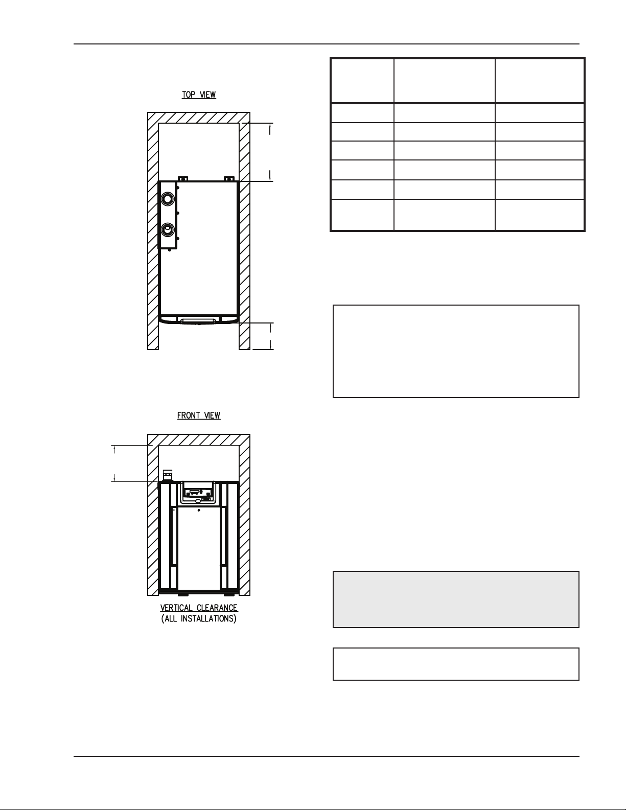
Indoor Installations
Heater
Side
Floor* 0” 0”
Rear 24” 24”
Right Side 0” 0”
Left Side 0” 0”
Top 12” 24”
Front Open 24”
Vent 1” 1”
*DO NOT install on carpeting.
Table D: Clearances — Indoor Installations
When installed according to the listed minimum clearances from combustible construction, these heaters
can be serviced without removing permanent structural construction around the heater. However, for ease
of servicing, we recommend a clearance of at least 24
in. in front, at least 24 in. on the rear and 24 in. above
the top of the heater. This will allow the heater to be
serviced in its installed location without movement or
removal of the heater.
Min. Clearances
rom Combustible
f
Surfaces
Recommended
ervice
S
Clearances
CAUTION: This boiler should be located in an area
where water leakage will not result in damage to the
area adjacent to the appliances or to the structure.
When such locations cannot be avoided, it is
recommended that a suitable catch pan, adequately
drained, be installed under the appliance. The pan
must not restrict air flow.
In addition, the heater shall be installed such that the
gas ignition system components are protected from
water (dripping, spraying, rain, etc.) during appliance
operation or service (circulator replacement, control
replacement, etc.).
If the heater needs to be secured to the ground, use
the holes in the anchoring legs on the heater.
Service clearances less than the minimum may
require removal of the heater to service either the heat
exchanger or the burner components. In either case,
the heater must be installed in a manner that will
enable the heater to be serviced without removing any
structure around the heater.
Outdoor Installations
These heaters are design-certified for outdoor installation. Heaters must not be installed under an overhang
unless clearances are in accordance with local installation codes and the requirements of the gas supplier.
Three sides must be open in the area under the overhang. Roof water drainage must be diverted away
from heaters installed under overhangs.
8
Page 9
24”
SERVICE
CLEARANCE
24”
SERVICE
CLEARANCE
24”
SERVICE
CLEARANCE
Heater
Side
Min. Clearances
from Combustible
urfaces
S
Recommended
Service
learances
C
Rear 24” 24”
Right Side 0” 0”
Left Side 0” 0”
Top Unobstructed 24”
Front Open 24”
Vent
Termination
Table E: Clearances — Outdoor Installations
12” 12”
Combustion and Ventilation Air
NOTE: Use of this boiler in construction areas
where fine particulate matter, such as concrete or
dry-wall dust, is present may result in damage to the
boiler that is not covered by the warranty. If operated
in a construction environment, a clean source of
combustion air must be provided directly to the
boiler.
Indoor Units
This heater must be supplied with sufficient quantities
of non-contaminated air to support proper combustion
and equipment ventilation. Combustion air can be supplied via conventional means where combustion air is
drawn from the area immediately surrounding the
heater, or via direct vent, where combustion air is
drawn directly from outside. All installations must comply with the requirements of the NFGC (U.S.) and
B149 (Canada), and all local codes.
Venting not shown for clarity. Heater must be vented per
instructions in this manual
Fig. 4: Minimum Clearances from Combustible
Surfaces — Indoor and Outdoor Installations
CAUTION: Combustion air must not be
contaminated by corrosive chemical fumes which
can damage the boiler and void the warranty. (See
the Appendix.)
NOTE: It is recommended that the intake vent be
insulated in cold climates to minimize sweating.
9
Page 10
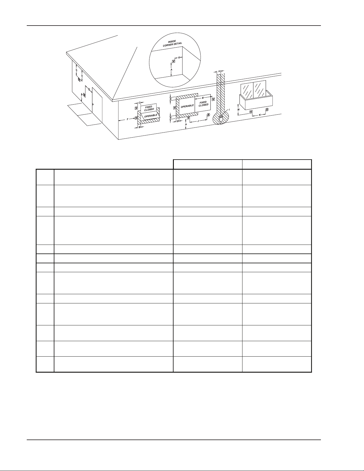
U.S. Installations
1
Canadian Insta llations
2
A
Clearance above grade, veranda, porch,
deck, or balcony
1 ft (30 cm) 1 ft (30 cm)
B
Clearance to window or door that may be
opened
4 ft (1.2m) below or to side
of opening; 1 foot (30 cm)
above opening
3 ft (91 cm)
C Clearance to permanently closed window **
D
Vertical clearance to ventilated soffit located
above the terminal within a horizontal distance of 2 ft (61cm) from the centerline of the
terminal
5 ft (1.5m) *
E Clearance to unventilated soffit **
F Clearance to outside corner **
G Clearance to inside corner 6 ft (1.83m) *
H
Clearance to each side of center line ex-
tended above meter/regulator assembly
*
3 ft (91 cm) within a height
15 ft above the me-
ter/regulator assembly
I Clearance to service regulator vent outlet * 6 ft (1.83m)
J
Clearance to non-mechanical air supply inlet
to building or the combustion air inlet to any
other appliance
4 ft (1.2m) below or to side
of opening; 1 ft (30 cm)
above opening
3 ft (91 cm)
K Clearance to mechanical air supply inlet
3 ft (91 cm) above if within
10 ft (3m) horizontally
6 ft (1.83m)
L
Clearance above paved sidewalk or paved
driveway located on public property
7 ft (2.13m)
7 ft (2.13m) t
M
Clearance under veranda, porch, deck or
balcony
* 12 in. (30 cm) TT
1
In accordance with the current ANSI Z223.1/NFP A 5 4 National Fuel Gas Code
2
In accordance with the current CAN/CGA-B149 Installation Codes
t Vent terminal shall not terminat e directly above sidewalk or paved driveway located between 2 single family dwellings that serves
both dwellings
TT Permitted only if veranda, porc h, deck, or balcony is fully open on a minimu m of two sides beneath the floor and top of terminal and
underside of ver anda, porch, deck or balcony is greater than 1 ft (30c m)
* Clearances in accordance with local installation codes and the requirements of the gas supplier
Fig. 5: Minimum Clearances from Vent/Air Inlet Terminations – Indoor and Outdoor Installations
Table F: Vent/Air Inlet Termination Clearances
10
Page 11

Combustion Air Filter
echanical room. All ducting must be self-supported.
m
This heater is supplied with an integral combustion air
filter. This filter will reduce the amount of particulates
that pass through the combustion system and heat
exchanger but will not protect against chemical inside
air contamination (See Appendix). The filter must be
checked periodically to verify that adequate combustion air is being supplied to the heater. See the
Maintenance section of this manual for information on
checking the filter and establishing service intervals.
Direct Vent
If outside air is drawn through the intake pipe directly
to the unit for combustion:
1. Install the combustion air ducting kit.
2. Install combustion air direct vent in accordance
with Fig. 23 (horizontal) or Fig. 24 (vertical) of this
manual.
3. Provide adequate ventilation of the space occupied by the heater(s) by an opening(s) for
ventilation air at the highest practical point communicating with the outdoors. The total
cross-sectional area shall be at least 1 in.2of free
area per 20,000 BTUH (111 mm2per kW) of total
input rating of all equipment in the room when the
opening is communicating directly with the outdoors or through vertical duct(s). The total
cross-sectional area shall be at least 1 in.2of free
area per 10,000 BTUH (222 mm2per kW) of total
input rating of all equipment in the room when the
opening is communicating with the outdoors
through horizontal duct(s).
4. In cold climates, and to mitigate potential freezeup, Raypak highly recommends the installation of
a motorized sealed damper on the air intake to
prevent the circulation of cold air through the
heater during the non-operating hours.
TruSeal™ Combustion Air
In addition to the 4 previous steps, combustion air may
be ducted directly to the heater by using PVC, CPVC
or sealed single-wall galvanized ducting. The duct will
attach directly to the air collar located on the rear of the
heater when the combustion air ducting kit is installed,
using three or four sheet metal screws (not supplied)
equally positioned around the circumference of the
duct. The screws and duct connection point must be
sealed with RTV (not supplied). TruSeal is generally
used when damaging contaminants are present in the
CAUTION: Use TruSeal combustion air if
amaging airborne contaminants are or may be
d
present in the boiler area. See the Appendix of this
manual regarding air contamination.
Conventional Combustion Air Supply
U.S. Installations
All Air from Inside the Building
The confined space shall be provided with TWO permanent openings communicating directly with an
additional room(s) of sufficient volume so that the combined volume of all spaces meets the criteria for a
room large in comparison (NFGC). The total input of all
gas utilization equipment installed in the combined
space shall be considered in making this determination. Each opening shall have a minimum free area of
2
per 1,000 BTUH (2,225 mm2per kW) of the total
1 in.
input rating of all gas utilization equipment in the confined space, but not less than 100 in.2(645 cm2). One
opening shall commence within 12 in. (305 mm) of the
top, and one opening shall commence within 12 in.
(305 mm) of the bottom of the enclosure. The minimum dimension of air openings shall be not less than
3 in. (76 mm) in any direction.
All Air from Outdoors
The confined space shall communicate with the outdoors in accordance with one of the methods below.
The minimum dimension of air openings shall not be
less than 3 in. (76 mm) in any direction. Where ducts
are used, they shall be of the same cross-sectional
area as the net free area of the openings to which they
connect.
1. Two permanent openings, one commencing
within 12 in. (305 mm) of the top, and one commencing within 12 in. (305 mm) of the bottom of
the enclosure, shall be provided. The openings
shall communicate directly, or by ducts, with the
outdoors or spaces (crawl or attic) that freely communicate with the outdoors.
a. Where directly communicating with the out-
doors or where communicating to the
outdoors through vertical ducts, each open-
ing shall have a minimum free area of 1 in.
per 4,000 BTUH (550 mm2per kW) of total
input rating of all equipment in the enclosure.
2
11
Page 12
b. Where communicating with the outdoors
through horizontal ducts, each opening shall
have a minimum free area of 1 in.2per 2,000
TUH (1,100 mm
B
2
er kW) of total input rat-
p
ing of all equipment in the enclosure.
2. One permanent opening, commencing within 12
n. (305 mm) of the top of the enclosure, shall be
i
permitted where the equipment has clearances of
at least 1 in. (25 mm) from the sides and back and
6 in. (152 mm) from the front of the appliance. The
opening shall directly communicate with the outdoors or shall communicate through a vertical or
horizontal duct to the outdoors or spaces that
freely communicate with the outdoors, and shall
have a minimum free area of:
2
a. 1 in.
per 3,000 BTUH (740 mm2per kW) of
the total input rating of all equipment located in
the enclosure, and
b. Not less than the sum of the areas of all vent
connectors in the confined space.
WARNING: Do not use the “one permanent
opening” method if the equipment room is under
negative pressure conditions.
Canadian Installations
and terminated 18 in. (450 mm) from the floor, but
not near piping. This air supply opening requirement shall be in addition to the air opening for
ventilation air required in 1. (above).
WARNING: Care must be taken to ensure that the
equipment room is not under negative pressure
conditions.
3. For heaters when air supply is provided by natural
air flow from outdoors for a power burner and
there is no draft regulator, drafthood or similar flue
gas dilution device installed in the same space, in
addition to the opening for ventilation air required
in 1., there shall be a permanent air supply opening(s) having a total cross-sectional area of not
less than 1 in.2for each 30,000 BTUH (74 mm2per
kW) of total rated input of the burner(s), and the
location of the opening(s) shall not interfere with
the intended purpose of the opening(s) for ventilation air referred to in 1. This opening(s) can be
ducted to a point not more than 18 in. (450 mm)
nor less than 6 in. (152 mm) above the floor level.
The duct can also “goose neck” through the roof.
The duct is preferred to be straight down 18 in.
(450 mm) from the floor, but not near piping.
4. Refer to the B149 Installation Code for additional
information.
CAUTION: All combustion air must be drawn from
the air outside of the building; the mechanical equipment room must communicate directly with the
outdoors.
1. Ventilation of the space occupied by the heater
shall be provided by an opening(s) for ventilation
air at the highest practical point communicating
with the outdoors. The total cross-sectional area of
such an opening(s) shall be at least 10% of the
area required in 2. and 3. (below), but in no case
shall the cross-sectional area be less than 10 in.
(65 cm2).
2. For heaters using a barometric damper in the vent
system, there shall be a permanent air supply
opening(s) having a cross section area of not less
2
than 1 in.
to and including 1 million BTUH, plus 1 in.
14,000 BTUH (160 mm
per 7,000 BTUH (320 mm2per kW) up
2
2
per kW) in excess of 1
per
million BTUH. This opening(s) shall be either
located at or ducted to a point not more than 18 in.
(450 mm) nor less than 6 in. (152 mm) above the
floor level. The duct can also “goose neck” through
the roof. The duct is preferred to be straight down
Water Piping
General
The heater should be located so that any water leaks
will not cause damage to the adjacent area or structures.
CAUTION: This boiler requires forced water
circulation when the burner is operating. See Table
G and Table H for minimum and maximum flow rates
2
and water pump selection. The pump must be
interlocked with the boiler to prevent heater
operation without water circulation.
NOTE: Minimum pipe size for in/out connections is
1-1/2” NPT for model 300 and 2” NPT for models 500
and 850. Verify proper flow rates and ∆T as instructed in this manual.
12
Page 13
Relief Valve Installation and Piping
To perform hydrostatic test:
WARNING: Pressure relief valve discharge piping
must be piped near the floor and close to a drain to
eliminate the potential of severe burns. Do not pipe
to any area where freezing could occur. Refer to
ocal codes.
l
The heater is supplied with a Section IV “HV” stamped
relief valve sized for the full input of the unit. The relief
valve assembly is shipped loose and must be mounted directly to the heater outlet. No valve shall be
installed between the heater and the relief valve. The
relief valve shall be mounted with its spindle vertical
(see Fig. 1, 2 and 3 on page 6). Relief valve discharge
piping shall provide no less than the cross sectional
area of the relief valve outlet and must be routed to a
safe point of discharge. Installation must comply with
all national, state and local codes.
WARNING: The pressure relief valve must be
installed at the outlet of the boiler. No valve is
permitted to be installed between the boiler and the
relief valve.
1. Connect fill water supply. With bleed valve open,
fill heater with water. When water flows from bleed
valve, shut off water. Close bleed valve. Carefully
fill the rest of the system, making sure to eliminate
ny entrapped air by using high-point vents. Close
a
feed valve. Test at standard operating pressure for
at least 24 hours.
2. Make sure constant gauge pressure has been
maintained throughout test.
3. Check for leaks. Repair if found.
Hydronic Heating
Pump Selection
In order to ensure proper performance of your heater
system, you must install a correctly-sized pump. Raypak recommends designing for a ∆T within the range
of 20°F to 40°F (5°C to 20°C). See Table G for acceptable flow rates for each model (∆T is the temperature
difference between the inlet and outlet water when the
heater is firing at full rate).
Temperature & Pressure Gauge
The temperature and pressure gauge is shipped loose
for field installation and must be installed within 12
inches of the boiler outlet (if possible) in an easily
readable location. Installation must comply with ASME
Section IV as well as all applicable national, state and
local codes.
Hydrostatic Test
Unlike many types of heaters, this heater does not require hydrostatic testing prior to being placed in
operation. The heat exchanger has already been factory-tested and is rated for 160 psi operating pressure.
However, Raypak does recommend hydrostatic testing of the piping connections to the heater and the rest
of the system prior to operation. This is particularly
true for hydronic systems using expensive glycolbased anti-freeze. Raypak recommends conducting
the hydrostatic test before connecting gas piping or
electrical supply.
Leaks must be repaired at once to prevent damage to
the heater. NEVER use petroleum-based stop-leak
compounds.
Feedwater Regulator
Raypak recommends that a feedwater regulator be installed and set at 12 psi minimum pressure at the
highest point of the system. Install a check valve or
back flow device upstream of the regulator, with a
manual shut-off valve as required by local codes.
Piping
All high points should be vented. A heater installed
above radiation level must be provided with a low water cut-off device (sales order option F-10). This
heater, when used in connection with a refrigeration
system, must be installed so that the chilled medium is
piped in parallel with the heater with appropriate
valves to prevent the chilled medium from entering the
heater.
The piping system of a hot water heater connected to
heating coils located in air handling units where they
may be exposed to circulating refrigerated air, must be
equipped with flow control valves or other automatic
means to prevent gravity circulation of the heater
water during the cooling cycle. It is highly recommended that the piping be insulated.
13
Page 14
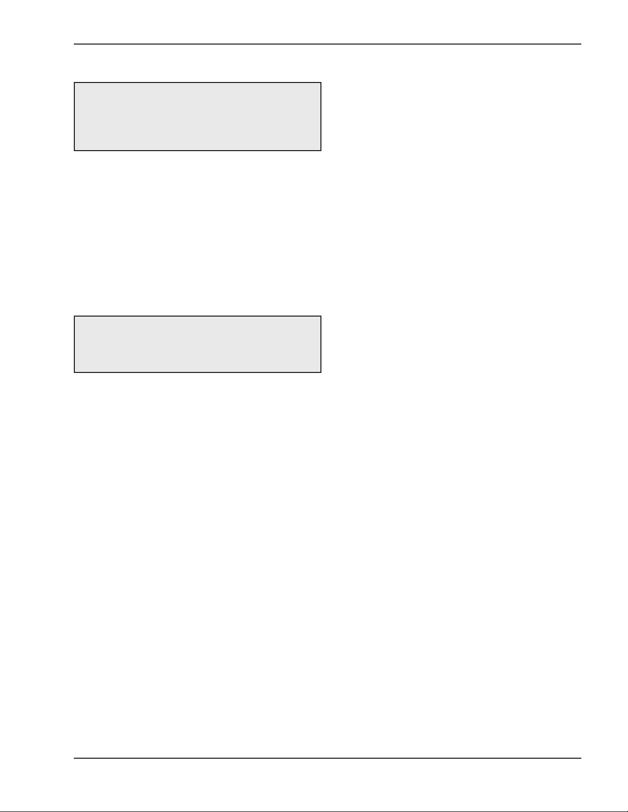
Air-Separation/Expansion Tank
Fig. 6: Air-Separation/Expansion Tank
All heaters should be equipped with a properly sized
expansion tank and air separator fitting as shown in
Fig. 6 above.
Three-Way Valves
Three-way valves intended to regulate system water
temperatures by reducing flow in the boiler should not
be used. Raypak heaters are high-recovery, low-mass
heaters which are not subject to thermal shock.
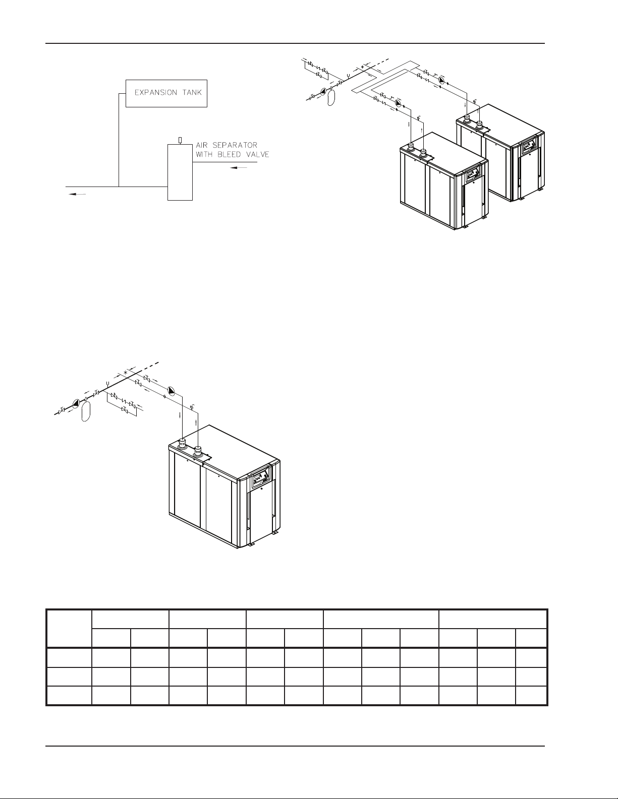
*Maximum 4 times the pipe diameter or 12”, whichever is less.
Fig. 8: Dual Heaters (Reverse/Return)
with Primary/Secondary Piping
Domestic Hot Water
When designing the water piping system for domestic
hot water applications, water hardness should be considered. Table H indicates the suggested flow rates for
soft and medium water. Hard water must be softened
for direct heating with the XFyre. Water hardness is
expressed in grains per gallon.
*Maximum 4 times the pipe diameter or 12”, whichever is less.
Fig. 7: Single Heater — Low-Temperature (Heat Pump)
Application with Primary/Secondary Piping
Model
No.
20°F ∆T 30°F ∆T 40°F ∆T Min. Flow Max. Flow
gpm ∆P (ft) gpm ∆P (ft) gpm ∆P (ft) gpm ∆P (ft) ∆T gpm ∆P (ft) ∆T
300 28 17 19 8 14 5 14 5 40 36 27 17
500 47 16 31 7 24 4 24 4 40 56 24 18
850 80 40 53 17 40 10 40 10 40 80 40 20
Notes: Basis for minimum flow is ∆T . Basis for maximum flow is gpm.
Table G: Heater Rates of Flow and Pressure Drops
14
Page 15
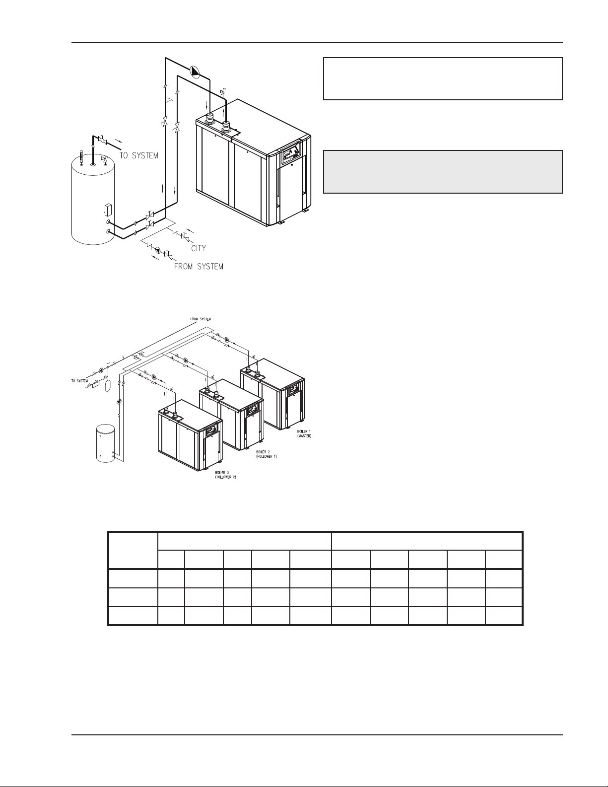
Fig. 9: Single Domestic Hot Water Heater and Storage
Tank
NOTE: If local codes require a vacuum relief valve,
acquire one locally and install per valve
manufacturer’s instructions.
Potable Water and Space Heating
CAUTION: When this heater is used for both
potable water and space heating, observe the
following to ensure proper operation.
1. All piping materials and components connected to
the water heater for the space heating application
shall be suitable for use with potable water.
2. Toxic chemicals, such as used for boiler treatment,
shall not be introduced into the potable water used
for space heating.
3. If the heater will be used to supply potable water,
it shall not be connected to any heating system or
components previously used with a non-potable
water heating appliance.
4. When the system requires water for space heating
at temperatures higher than 140°F (60°C), a
means such as a mixing valve shall be installed to
temper the water in order to reduce scald hazard
potential.
Fig. 10: Multiple Boilers — Reverse Return,
Primary/Secondary Piping with Indirect DHW
Model
No.
Soft (0–4 grains per gallon) Medium (5–15 grains per gallon)
∆T gpm ∆P MTS SHL ∆T gpm ∆P MTS SHL
300 30 19 8 1.5 10 20 28 17 1.5 20
500 30 31 7 2 8 20 47 16 2 18
850 30 53 17 2 20 20 80 40 2 46
∆T = Temperature rise, °F.
∆P = Pressure drop through heat exchanger, ft.
SHL = System head loss, ft (based on heater and tank placed no more than 5 ft apart and equivalent length of 25 ft of tubing).
gpm = Gallons per minute, flow rate.
MTS = Minimum tubing size.
CAUTION: For scale free operation with Medium water (5–15 grains per gallon of total hardness), the operating control must NOT
be set higher than 130°F. For higher than 130°F operation, or Hard water (>16 grains per gallon of total hardness), a water softener/treatment system must be utilized.
Table H: Domestic Water Heater Flow Rate Requirements
15
Page 16
Gas Supply
DANGER: Make sure the gas on which the heater
will operate is the same type as specified on the rating plate.
CAUTION: Do not use Teflon tape on gas line pipe
thread. A pipe compound rated for use with natural
and propane gases is recommended. Apply
sparingly only on male pipe ends, leaving the two
nd threads bare.
e
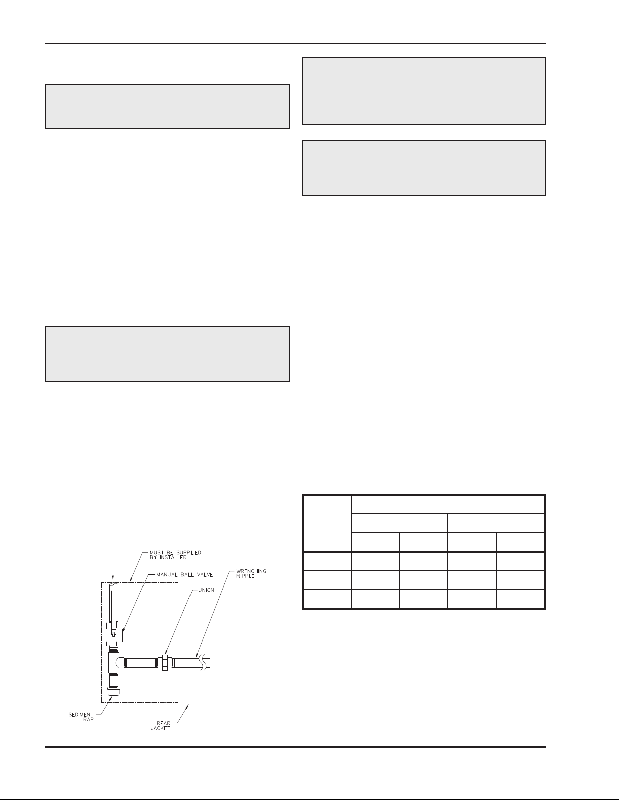
Gas piping must have a sediment trap ahead of the
heater gas controls, and a manual shut-off valve located outside the heater jacket. It is recommended
that a union be installed in the gas supply piping adjacent to the heater for servicing. The gas supply
pressure to the heater must not exceed 10.5 in. WC for
natural gas or 13.0 in. WC for propane gas. A poundsto-inches regulator must be installed to reduce the gas
supply pressure if it is higher than noted above. This
regulator should be placed a minimum distance of 10
times the pipe diameter upstream of the heater gas
controls. Refer to Table J for maximum pipe lengths.
Gas Supply Connection
CAUTION: The heater must be disconnected from
the gas supply during any pressure testing of the gas
supply system at test pressures in excess of 1/2 psi
(3.45 kPa).
The heater must be isolated from the gas supply piping system by closing the upstream manual shut-off
valve during any pressure testing of the gas supply
piping system at test pressures equal to or less than
1/2 psi (3.45 kPa). Relieve test pressure in the gas
supply line prior to re-connecting the heater and its
manual shut-off valve to the gas supply line. FAILURE
TO FOLLOW THIS PROCEDURE MAY DAMAGE
THE GAS VALVE. Over-pressurized gas valves are
not covered by warranty. The heater and its gas connections shall be leak-tested before placing the
appliance in operation. Use soapy water for leak test.
DO NOT use an open flame.
CAUTION: Support gas supply piping with
hangers, not by the heater or its accessories. Make
sure the gas piping is protected from physical
damage and freezing, where required.
Gas Supply Pressure
A minimum of 4.0 in. WC and a maximum of 10.5 in.
WC upstream gas pressure is required under load and
no-load conditions for natural gas. A minimum of 4.0
in. WC and a maximum of 13.0 in. WC is required for
propane gas. The gas pressure regulator(s) supplied
on the heater is for low-pressure service. If upstream
pressure exceeds these values, an intermediate gas
pressure regulator, of the lockup type, must be
installed.
When connecting additional gas utilization equipment
to the gas piping system, the existing piping must be
checked to determine if it has adequate capacity for
the combined load. The gas valve pressure regulator
on the heater is nominally preset as noted in Table I.
During normal operation, carbon dioxide should be 8.5
to 9.0% at full fire for natural gas and between 9.0 and
9.5% for propane gas. Carbon monoxide should be
‹150 ppm.
Manifold Pressure (in. WC)
Model
No.
Natural Gas Propane Gas
High Low High Low
Fig. 10: Gas Supply Connection
300 -0.2 -0.1 -0.2 -0.1
500 -0.3 -0.1 -0.3 -0.1
850 -3.2 -0.2 -2.7 -0.1
NOTE: Manifold pressures should be ±0.3 in. WC.
Table I: Manifold Gas Pressure Settings
16
Page 17
Model
o.
N
3/4” NPT 1” NPT 1-1/4” NPT 1-1/2” NPT 2” NPT
N P N P N P N P N P
00
3
5
1
0
3
5
4
00
1
500 10 15 40 65 150 150 350
850 15 25 55 55 125 175 450
Natural Gas – 1,000 BTU/ft3, 0.60 specific gravity at 0.5 in. WC pressure drop
Propane Gas – 2,500 BTU/ft3, 1.53 specific gravity at 0.6 in. WC pressure drop
Table J: Maximum Equivalent Pipe Length
Electrical Power Connections
Installations must follow these codes:
• National Electrical Code and any other national,
state, provincial or local codes or regulations having jurisdiction.
• Safety wiring must be NEC Class 1.
• Heater must be electrically grounded as required
by the NEC.
• In Canada, CSA C22. 1 C.E.C. Part 1.
The XFyre 300–850 heaters are wired for 120 V single-phase 60 Hz power. Consult the wiring diagram
shipped with the heater. Before starting the heater,
check to ensure proper voltage to the heater and
pump(s). A larger circuit breaker may be needed for
pumps larger than 1/4 hp.
Boiler pumps up to 1 hp and DHW pumps up to 1/4 hp
get their power supply directly from the heater power
supply (connections in rear wiring box). XFyre heaters
75
1
00
4
90
3
may power up to two pumps directly (1 hp max boiler
pump, 3 A max DHW pump) and may control a third
system pump, depending on the configuration of the
controller and the installation requirements. Install a
circuit breaker sized sufficiently for both the heater and
the pump(s). DHW pumps larger than 1/4 hp or 3 A
must use a separate power supply and run the power
through an external field supplied pump contactor. Use
appropriately-sized wire as defined by NEC, CSA
and/or local codes. All primary wiring should be 125%
of minimum rating.
If any of the original wire as supplied with the heater
must be replaced, it must be replaced with 105°C wire
or its equivalent.
All 120 VAC field wiring connections to the XFyre
heater are made inside the rear wiring box as shown
in Fig. 11a. Power to the XFyre heater should be connected to terminals 1, 2, and 3 as shown in Fig. 11a.
Low voltage wiring is connected to the field wiring
board at the front of the unit. Sensors, Thermostat (TT)
Fig. 11a: Wiring Electrical Connections
Fig. 11b: Wiring Electrical Connections
Cascade Master
17
Page 18

contacts, optional 0–10 VDC control wiring and cascade connections are wired into the front mounted
field wiring board as shown in Fig. 15–19.
Field-Connected Controllers
t is strongly recommended that all individually-pow-
I
ered control modules and the heater should be
supplied from the same power source.
NOTE: Field-supplied isolation relays should be
installed when field-connected controllers are
mounted more than 50 equivalent feet (18 AWG)
from heater.
Check the Power Source
NOTE: Minimum 18 AWG, 105°C, stranded wire
must be used for all low voltage (less than 30 volts)
external connections to the unit. Solid conductors
should not be used because they can cause
excessive tension on contact points. Install conduit
as appropriate. All high voltage wires must be the
same size (105°C, stranded wire) as the ones on the
unit or larger.
Fig. 13: Multi-meter
Making the Electrical Connections
Refer to Fig. 11a–19.
1. Verify that circuit breaker is properly sized by
referring to heater rating plate. A dedicated circuit
breaker should be provided and sized for the
heater and all pumps powered through the heater.
NOTE: Current draw noted on rating plate does not
include pump current.
2. Turn off all power to the heater. Verify that power
has been turned off by testing with a multi-meter
prior to working with any electrical connections or
components.
3. Observe proper wire colors while making electrical connections. Many electronic controls are
polarity sensitive. Components damaged by improper electrical installation are not covered by
warranty.
Fig. 12: Wiring Connections
WARNING: Using a multi-meter, check the
following voltages at the circuit breaker panel prior to
connecting any equipment. Make sure proper
polarity is followed and house ground is proven.
(See Fig. 13.)
Check the power source:
AC = 108 VAC Minimum, 132 VAC MAX
AB = 108 VAC Minimum, 132 VAC MAX
BC = <1 VAC Maximum
4. Provide overload protection and a disconnect
means for equipment serviceability as required by
local and state code.
5. Install heater controls, thermostats, or building
management systems in accordance with the
applicable manufacturers’ instructions.
6. Conduit should not be used as the earth ground.
NOTE: A grounding electrode conductor shall be
used to connect the equipment grounding
conductors, the equipment enclosures, and the
grounded service conductor to the grounding
electrode.
18
Page 19

Field Wiring Connections
DIMPLES FOR
ALTERNATE
LOW VOLTAGE
WIRE ROUTING
FIELD
WIRING
BOARD
DANGER: SHOCK HAZARD
CAUTION: Label all wires prior to disconnection
when servicing controls. Wiring errors can cause im-
roper and dangerous operation. Verify proper
p
operation after servicing.
Make sure electrical power to the heater is disconnected to avoid potential serious injury or damage to
components.
Fig. 14: Rear Wiring Location
Fig. 15: Front Wiring Location
Fig. 16: XFyre Single Heater Control
Wiring the Thermostat
1. Connect the room thermostat to the terminals
marked THERMOSTAT in the electrical junction
box (shown in Fig. 16). Alternately, any dry contact
closure across these terminals will enable the
XFyre unit to run. Caution should be used to
ensure neither of the terminals becomes connected to ground.
2. Mount the thermostat on an inside wall as central
as possible to the area being heated, but away
from drafts or heat producing devices, such as television sets, that could effect the ability of the
thermostat to measure the room temperature
accurately.
3. If the thermostat is equipped with an anticipator,
and it is connected directly to the XFyre boiler, the
anticipator should be set at .1 amps. If the thermostat is connected to other devices, the anticipator
should be set to match the power requirements of
the device it is connected to. See the instruction
manual for the connected devices for further information.
19
Page 20

Wiring the Outdoor Sensor
1. There is no connection required if an outdoor sensor is not used in this installation.
. If using an Outdoor Sensor, connect the wires for
2
sensor to the terminals marked OUTDOOR SEN
(shown in Fig. 16) in the electrical junction box.
Caution should be used to ensure neither of these
terminals becomes connected to ground.
3. Use a minimum 22 AWG wire for runs of 100 feet
or less, and minimum 18 AWG wire for runs of up
to 150 feet.
4. Mount the outdoor sensor on an exterior surface of
the building, preferably on the north side in an
area that will not be affected by direct sunlight and
that will be exposed to varying weather conditions.
Wiring the Indirect Sensor
1. There is no indirect sensor connection required if
an indirect water heater is not used in the installation.
2. The XFyre boiler will operate an indirect fired
water heater with either a thermostat type aquastat installed in the indirect tank or a Raypak tank
sensor. When a tank sensor is used, the XFyre
control will automatically detect its presence and a
demand for heat from the indirect water heater will
be generated when the tank temperature falls
below the user settable setpoint by more than the
user selectable offset. The demand will continue
until the sensor measures that the indirect water
heater temperature is above the setpoint.
Wiring the Optional 0–10 Volt
Building Control Signal
1. A signal from a building management system may
be connected to the XFyre boiler to enable remote
control. This signal should be a 0–10 volt positive
C signal. When this input is enabled using the
D
installer menu, a building control system can be
used to control either the setpoint temperature or
the heat output of the XFyre boiler. The control
interprets the 0–10 volt signal as follows. When the
signal is between 0 and 1 volt, the XFyre boiler will
be in stand by mode, not firing. When the signal
rises above 1 volt, the XFyre boiler will ignite. As
the signal continues to rise towards its maximum
of 10 volts, the XFyre boiler will increase either in
setpoint temperature or firing rate, depending on
the setting of screen 17 in the installer menu. See
the Installer Menu section for details on the setting
of screens 16 and 17 for this option.
2. Connect a building management system or other
auxiliary control signal to the terminals marked
+0–10 V and -0–10 V in the electrical junction box
(shown in Fig. 16) Caution should be used to
ensure that the +0–10 V connection does not
become connected to ground.
Wiring the Cascade System
Communication Bus
1. Use standard CAT3 or CAT5 computer network
patch cables to connect the communication bus
between each of the boilers. These cables are
readily available at any office supply, computer,
electronic, department or discount home supply
store in varying lengths.
3. Connect the indirect tank sensor to the terminals
marked DHW SENSOR (shown in Fig. 16) in the
electrical junction box. Caution should be used to
ensure neither of these terminals becomes connected to ground.
2. It is recommended that the shortest length cable
possible be used to reach between the boilers and
create a neat installation. Do not run unprotected
cables across the floor or where they will become
wet or damaged. Avoid running communication
cables parallel with, or close to or against, high
voltage (120 volt or greater) wiring. Raypak recommends that the total maximum length of
communication bus cables not exceed 200 feet.
20
Page 21

Fig. 17: XFyre Cascade System Wiring
3. Create a hole to route the communication cables
through where the dimples are in the side of the
cabinet (see Fig. 15), or route the wires to the rear
junction box and out of the cabinet.
4. Connect the boilers in a daisy chain configuration
as shown in Fig. 17 above. It is best to wire the
boilers using the shortest wire runs rather than trying to wire them in the order that they are
addressed. The communication bus jacks on the
customer connection panel are interchangeable
so you can use either one or both in any order to
connect the cable to. If you have connected the
boilers to each other properly, two of the boilers
will have one open connection port on them.
21
Page 22

*
* - May be configured as DHW SENSOR for
single boiler Cascade with Indirect
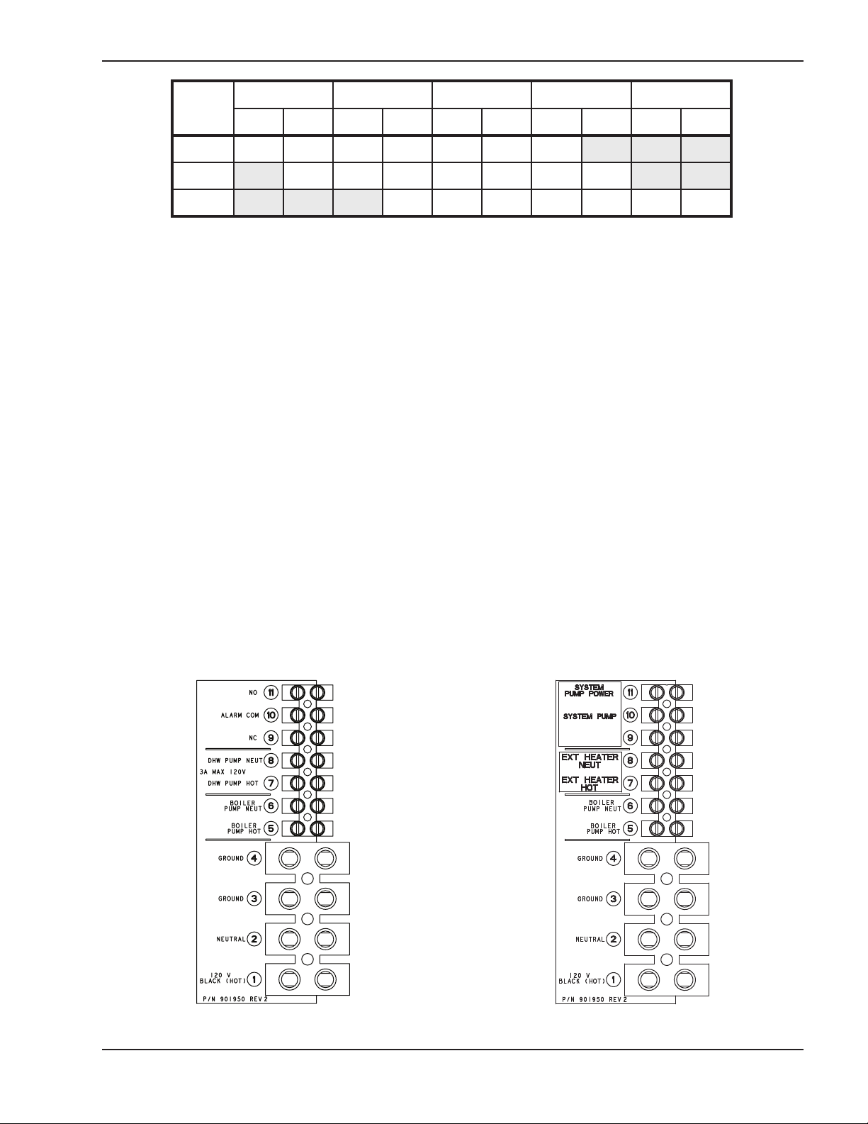
5. Connect the boiler pump to the terminals marked
BOILER PUMP NEUT (#6), BOILER PUMP HOT
(#5), and GROUND (#4).
6. Connect the system pipe sensor to the terminals
arked SYS SENSOR, as shown in Fig. 18.
m
7. Connect the outdoor sensor (if used) to the terminals marked OUTDOOR SEN.
8. Connect the signal to start the system to the terminals marked THERMOSTAT.
NOTE: This signal can come from a room
thermostat or a dry contact closure. No power of any
voltage should be fed into either of these terminals.
Fig. 18: XFyre Cascade Master
Cascade Master Pump and
Sensor Wiring
1. On the boiler designated as the Cascade Master,
apply the System Sensor and DHW Sensor decals
(included) to the field wiring board as shown in Fig.
18. Apply the SYSTEM PUMP and EXT HEATER
labels to the wiring electrical connections terminal
strip as shown in Fig. 11b on page 17.
2. Connect the system pump hot wire to terminal #11,
marked SYSTEM PUMP (see Fig 11b).
3. Connect the system pump neutral to terminal #6,
marked BOILER PUMP NEUT, and the pump
ground wire to terminal #3, marked GROUND, at
the rear terminal strip.
4. Connect a jumper wire from terminal #1, marked
120 V BLACK (HOT), terminal #11, marked SYSTEM PUMP POWER, at the rear terminal strip.
Fig. 19: XFyre Cascade Follower
22
Page 23

Cascade Follower Pump
and Sensor Wiring
. Connect the boiler pump to the terminals marked
1
BOILER PUMP NEUT (#6), BOILER PUMP HOT
#5), and GROUND (#4) at the rear terminal strip.
(
2. If you are using an indirect fired water tank connected directly to the follower boiler, connect the
pump for it to the terminals marked DHW PUMP
NEUT (#8), DHW PUMP HOT (#7), and GROUND
(#3) at the rear terminal strip.
If you desire, an alarm bell or light can be connected
to the alarm contacts of the follower boiler. Optionally,
the normally-closed alarm contact may be used to turn
a device off if the boiler goes into lockout mode. The
alarm contacts are rated 5 amps at 120 VAC.
To connect an alarm device, connect the power for the
device to the ALARM COM terminal. Connect the
alarm device hot wire to the ALARM NO terminal.
Connect the neutral or return of the alarm device to the
neutral or return of the power for the alarm device.
To connect a device that should be powered off during
a boiler lockout condition, follow the same instructions
as above except use the ALARM NC terminal rather
than the ALARM NO terminal.
Note that in a cascade system the alarm output of the
boiler addressed as #1 will also be active if the master
boiler has a lockout condition. The alarm output of boilers addressed as 2–7 will only sound if a lockout
condition occurs on that specific boiler.
CAUTION: Proper installation of flue venting is
critical for the safe and efficient operation of the
boiler.
Venting
General
Appliance Categories
Heaters are divided into four categories based on the
pressure produced in the exhaust and the likelihood of
condensate production in the vent.
Category I – A heater which operates with a non-positive vent static pressure and with a vent gas
temperature that avoids excessive condensate production in the vent.
Category II – A heater which operates with a non-positive vent static pressure and with a vent gas
temperature that may cause excessive condensate
roduction in the vent.
p
ategory III – A heater which operates with a positive
C
vent pressure and with a vent gas temperature that
avoids excessive condensate production in the vent.
Category IV – A heater which operates with a positive
vent pressure and with a vent gas temperature that
may cause excessive condensate production in the
vent.
See Table K for appliance category requirements.
NOTE: For additional information on appliance
categorization, see the ANSI Z21.13 Standard and
the NFGC (U.S.), or B149 (Canada), or applicable
provisions of local building codes.
CAUTION: Condensate drains for the vent piping
are required for installations of the XFyre. Follow
vent manufacturer instructions for installation and
location of condensate drains in the vent.
Condensate drain traps must be primed with water to
prevent gas flue leak and must be routed to an
appropriate container for neutralization before disposal, as required by local codes.
WARNING: Contact the manufacturer of the vent
material if there is any question about the appliance
categorization and suitability of a vent material for
application on a Category IV vent system. Using
improper venting materials can result in personal
injury, death or property damage.
CAUTION: Raypak recommends the use of a condensate neutralizer, sales order option Z-12.
Use only approved PVC or CPVC vent materials (in
Canada, ULC-S636 approved plastic materials must
be used) or special gas vent pipes listed for use with
Category IV gas burning heaters, such as the AL29-4C
stainless steel vents offered by Heat Fab Inc. (800772-0739), Protech System, Inc. (800-766-3473),
Z-Flex (800-654-5600) or American Metal Products
(800-423-4270). Pipe joints must be positively sealed.
Follow the vent manufacturer’s installation instructions
carefully. Vent installations shall be in accordance with
Part 7, Venting of Equipment, of the NFGC, ANSI
Z223.1/NFPA 54, Section 7, Venting Systems and Air
Supply for Appliances, of the B149 Code, or applicable
provisions of the local building codes.
23
Page 24

Combustion
Air Supply
Exhaust
Configuration
Heater Venting
Category
Certified Vent
Materials
Combustion Air
Inlet Material
From Inside Building
(Non-Direct Venting)
From Outside Building
(Direct Venting)
WARNING: Do not use foam core or cellular core
pipe for venting.
Vertical Venting
orizontal Through-
H
the-Wall Venting
Vertical Venting
Horizontal Through-
the-Wall Venting
Table K: Venting Category Requirements
Support of Vent Stack
The weight of the vent stack or chimney must not rest
on the heater vent connection. Support must be provided in compliance with applicable codes. The vent
should also be installed to maintain proper clearances
from combustible materials. Use insulated vent pipe
spacers where the vent passes through combustible
roofs and walls.
When using PVC or CPVC venting on models 300 and
500, insert the vent pipe 3-5 inches into the unit and
provide rigid support to the vent, so that it will not shift
laterally.
Vent Terminal Location
(Canada Only: ULC-
636 PVC and CPVC)
S
Stainless Steel,
IV
WARNING: DO NOT insulate PVC or CPVC vent
pipe.
5. The bottom of the vent terminal and the air intake
6. Single-wall Category IV metal vent pipe shall not
7. Through-the-wall vents for Category IV appli-
8. Locate and guard vent termination to prevent acci-
AL29-4C, ANSI/ASTM
D1785 Sch 40 PVC,
ANSI/ASTM F441 Sch
40 CPVC
shall be located at least 12 in. above grade, including normal snow line.
be used outdoors in cold climates for venting gasfired equipment without insulation.
ances shall not terminate over public walkways or
over an area where condensate or vapor could
create a nuisance or hazard or could be detrimental to the operation of regulators, relief valves, or
other equipment.
dental contact by people or pets.
Galvanized Steel,
PVC, ABS,
CPVC
1. Condensate can freeze on the vent cap. Frozen
condensate on the vent cap can result in a blocked
flue condition.
NOTE: During winter months check the vent cap
and make sure no blockage occurs from build-up of
snow or ice.
2. Give special attention to the location of the vent
termination to avoid possibility of property damage or personal injury.
3. Gases may form a white vapor plume in winter.
The plume could obstruct a window view if the termination is installed near windows.
4. Prevailing winds, in combination with below-freezing temperatures, can cause freezing of
condensate and water/ice build-up on buildings,
plants or roofs.
9. DO NOT terminate vent in window well, stairwell,
alcove, courtyard or other recessed area.
10. DO NOT terminate above any door, window, or
gravity air intake. Condensate can freeze, causing
ice formations.
11. Locate or guard vent to prevent condensate from
damaging exterior finishes. Use a rust-resistant
sheet metal backing plate against brick or masonry surfaces.
12. DO NOT extend exposed vent pipe outside of
building beyond the minimum distance required
for the vent termination. Condensate could freeze
and block vent pipe.
NOTE: When using PVC vent termination, insert the
two round stainless mesh screens provided with the
unit into the tee.
24
Page 25

U.S. Installations
Refer to the latest edition of the National Fuel Gas
Code.
ent termination requirements are as follows:
V
1. Vent must terminate at least 4 ft below, 4 ft horizontally from or 1 ft above any door, window or
gravity air inlet to the building.
2. Less than 7 ft (2.13 m) above a paved sidewalk or
paved driveway located on public property.
3. Within 6 ft (1.8 m) of a mechanical air supply inlet
to any building.
. Above a meter/regulator assembly within 3 ft (915
4
mm) horizontally of the vertical centerline of the
regulator.
2. The vent must not be less than 7 ft above grade
when located adjacent to public walkways.
3. Terminate vent at least 3 ft above any forced air
inlet located within 10 ft.
4. Vent must terminate at least 4 ft horizontally, and
in no case above or below unless 4 ft horizontal
distance is maintained, from electric meters, gas
meters, regulators, and relief equipment.
5. Terminate vent at least 6 ft away from adjacent
walls.
6. DO NOT terminate vent closer than 5 ft below roof
overhang.
7. The vent terminal requires a 12 in. vent terminal
clearance from the wall.
8. Terminate vent at least 1 ft above grade, including
normal snow line.
9. Multiple direct vent installations require a 4 ft
clearance between the ends of vent caps located
on the same horizontal plane.
WARNING: The Commonwealth of Massachusetts
requires that sidewall vented heaters, installed in
every dwelling, building or structure used in whole or
in part for residential purposes, be installed using
special provisions as outlined on page 53 of this
manual.
Installations in Canada
5. Within 6 ft (1.8 m) of any gas service regulator
vent outlet.
6. Less than 1 ft (305 mm) above grade level.
7. Within 3 ft (915 mm) of a window or door which
can be opened in any building, any non-mechanical air supply inlet to any building or the
combustion air inlet of any other appliance.
8. Underneath a verandah, porch or deck, unless the
verandah, porch or deck is fully open on a minimum of two sides beneath the floor, and the
distance between the top of the vent termination
and the underside of the verandah, porch or deck
is greater than 1 ft (305 mm).
Venting Installation Tips
Support piping:
• horizontal runs—at least every 5 ft (1.5m)
• vertical runs—use braces
• under or near elbows
WARNING: Examine the venting system at least
once a year. Check all joints and vent pipe
connections for tightness, corrosion or deterioration.
Venting Configurations
For heaters connected to gas vents or chimneys, vent
installations shall be in accordance with the NFGC
(U.S.), or B149 (Canada), or applicable provisions of
local building codes.
Refer to latest edition of the B149 Installation Code.
A vent shall not terminate:
1. Directly above a paved sidewalk or driveway
which is located between two single-family dwellings and serves both dwellings.
Vertical Venting (Category IV)
CAUTION: This venting system requires the
installation of a condensate drain in the vent piping
per the vent manufacturer’s instructions. Failure to
install a condensate drain in the venting system will
void all warranties on this boiler.
25
Page 26

odel No.
M
Certified Vent
Material
ent and
V
Intake Air
Vent Size
(in.)
Vertical Vent Height1(ft)
Min. Max.
ombustion
C
Air Intake
Pipe
Material
Vertical Air
nlet Max.
I
Length* (ft)
300
(Canada Only:
ULC-S636 PVC
and CPVC)
4
Stainless Steel,
AL29-4C,
0 100
ANSI/ASTM D1785
Sch 40 PVC,
ANSI/ASTM F441
850 6
1
Vent lengths are based on a lateral length of 2 ft. Refer to the latest edition of the NFGC for further details.
* Subtract 10 ft per elbow. Max. 4 elbows.
Installation
Sch 40 CPVC
Table L: Category IV Vertical Vent & Vertical Direct Vent
The distance of the vent terminal from adjacent public
walkways, adjacent buildings, open windows and
The maximum and minimum venting length for this
Category IV appliance shall be determined per the
NFGC (U.S.) or B149 (Canada).
building openings must be consistent with the NFGC
(U.S.) or B149 (Canada). Vents supported only by
flashing and extending above the roof more than 5 ft
should be securely guyed or braced to withstand snow
The diameter of vent flue pipe should be sized accord-
and wind loads.
ing to the NFGC (U.S.) and Appendix B of B149
(Canada). The minimum flue pipe diameter for conventional venting is: 4 in. (102mm) for Models 300 and
500, and 6 in. (152mm) for Model 850.
Galvanized
Steel,
PVC, ABS,
CPVC
100500
The connection from the appliance vent to the stack
must be as direct as possible and shall be the same diameter as the vent outlet. The horizontal breaching of
a vent must have an upward slope of not less than 1/4
inch per linear foot from the heater to the vent terminal. The horizontal portions of the vent shall also be
supported for the design and weight of the material
employed to maintain clearances and to prevent physical damage or separation of joints.
NOTE: A vent adapter (field-supplied) may be required to connect the Category IV vent to the boiler.
Termination
The vent terminal should be vertical and should terminate outside the building at least 2 ft above the highest
point of the roof that is within 10 ft. The vent cap
should have a minimum clearance of 4 ft horizontally
from and in no case above or below (unless a 4 ft horizontal distance is maintained) electric meters, gas
meters, regulators and relief equipment.
Fig. 20: Vertical Venting
26
Page 27

NOTE: When using PVC vent termination, insert the
round stainless mesh screens provided with the unit
into the tee and terminals.
CAUTION: A listed vent cap terminal suitable for
onnection to the Cat IV vent materials, adequately
c
sized, must be used to evacuate the flue products
from the boilers.
Common Venting
on venting system are located and other spaces
m
of the building. Turn on clothes dryers and any
appliance not connected to the common venting
system. Turn on any exhaust fans, such as range
oods and bathroom exhausts, so they will oper-
h
ate at maximum speed. Do not operate a summer
xhaust fan. Close fireplace dampers.
e
(d) Place in operation the appliance being inspected.
Follow the lighting instructions. Adjust thermostat
so appliance will operate continuously.
The NFGC does not address sizing guidelines for the
common venting of multiple Category IV heaters. This
is covered in the NFGC under “Engineered Vent Systems”. Table M provides volumes of flue products at
full fire for the calculation of appropriate vent and
extractor sizing for common venting.
WARNING: Vent connectors serving any other
appliances shall not be connected into any portion of
mechanical draft systems operating under a positive
pressure. If an XFyre boiler is installed to replace an
existing boiler, the vent system MUST be verified to
be of the correct size and of Category IV AL29-4C
vent material or approved PVC/CPVC construction
(in Canada, ULC-S636 approved plastic materials
must be used). If it is NOT, it MUST be replaced.
NOTE: For extractor sizing, typical CO2levels are
8.5% for natural gas and 9.5% for propane gas and
flue temperatures of approximately 150°F.
At the time of removal of an existing boiler, the following steps shall be followed with each appliance
remaining connected to the common venting system
placed in operation, while the other appliances remaining connected to the common venting system are not
in operation:
(a) Seal any unused openings in the common venting
system.
(b) Visually inspect the venting system for proper size
and horizontal pitch and make sure there is no
blockage or restriction, leakage, corrosion and
other deficiencies which could cause an unsafe
condition.
(e) After it has been determined that each appliance
remaining connected to the common venting system properly vents when tested as outlined above,
return doors, windows, exhaust fans, fireplace
dampers and any other gas burning appliance to
their previous conditions of use.
(f) Any improper operation of the common venting
system should be corrected so that the installation
conforms with the latest edition of the National
Fuel Gas Code, ANSI Z223.1 and/or CAN/CSA
B149. When re-sizing any portion of the common
venting system, the common venting system
should be re-sized to approach the minimum size
as determined using the appropriate tables in Part
11 of the National Fuel Gas Code, ANSI Z223.1
and/or CAN/CSA B149.
Volume of
Flue Products
(CFM)
80
Model No.
300
Vent Size
(inches)
4
500 130
850 6 220
NOTE: Data for 100% firing rate.
Table M: Volume of Flue Products Data
NOTE: Vent and intake piping must be supported so
that the weight of the venting is not transfered to the
unit. Horizontal runs of vent and intake piping must
be supported to prevent sagging.
(c) As much as possible, close all building doors and
windows and all doors between the space in which
the appliances remaining connected to the com-
27
Page 28

Note: Heaters rotated to show venting connections.
12” MIN ABOVE SNOWLINE
Fig. 21: Typical Common Venting
Horizontal Through-the-Wall Direct
Venting (Category IV)
Refer to Table F and local codes.
Fig. 22: Horizontal Through-the-Wall Venting
Refer to Table F and local codes.
Fig. 23: Horizontal Through-the-Wall Direct Venting
28
Page 29

NOTE: While a drain connection is required in the
ent of all XFyre installations, the drain can be ac-
v
complished in several different ways. The figures in
this manual show the drain in a vent tee, however,
this can also be accomplished using an inline collec-
or for condensing stacks or an inline vertical or
t
horizontal collector available from several of the
isted vent manufacturers.
l
equivalent ft, an appropriately sized variable-speed
extractor must be used. Each elbow used is equal to
10 ft of straight pipe with a maximum of 4 elbows each
on the air intake and vent.
The vent and air intake runs should be balanced to
provide approximately the same equivalent length.
The vent cap and air intake elbow are not considered
in the overall length of the venting system.
CAUTION: This venting system requires the
installation of a condensate drain in the vent piping
per the vent manufacturer’s instructions. Failure to
install a condensate drain in the venting system will
void all warranties on this boiler.
Installation
These installations utilize the heater-mounted blower
to draw combustion air and to vent the combustion
products to the outdoors. The combustion air intake
and the vent are installed horizontally through the wall
to the outdoors. Adequate ventilation air must be supplied to the equipment room in accordance with the
NFGC (U.S.) or B149 (Canada).
The total length of the horizontal through-the-wall
direct vent system should not exceed 200 equivalent ft
in length. If combined vent/intake run exceeds 200
The vent must be installed to prevent flue gas leakage.
Care must be taken during assembly to ensure that all
joints are sealed properly and are airtight. The vent
must be installed to prevent the potential accumulation
of condensate in the vent pipes. It is required that:
1. The vent must be installed with condensate drains
as directed by the vent manufacturer.
2. The vent must be installed with a slight upward
slope of not less than 1/4 inch per foot of horizontal run to the vent terminal.
Termination
The vent cap MUST be mounted on the exterior of the
building. The vent cap cannot be installed in a well or
below grade. The vent cap must be installed at least 1
ft above ground level and above normal snow levels.
Only Raypak-approved vent caps may be used. The
vent terminal must be located NO CLOSER than 12”
off the wall.
Model No.
300
500
Size
(in.)
4
Approved Intakes
PVC 90° Elbow,
Galvanized 90°
Elbow SS 90°
850 6
*Must be ULC-S636 materials in Canada.
WARNING: No substitutions of flue pipe or vent
cap material are allowed. Such substitutions would
jeopardize the safety and health of inhabitants.
Approved Plastic
Terminals
4" PVC Tee, Sch
Sch 40
40*
6" PVC Tee, Sch
Elbow
Table N: Horizontal Vent and Air Intake Terminals
40*
FasNSeal FSTT4, Z-Vent 2SVSTTF04
FasNSeal FSTT6, Heat Fab 9690TEE
29
Approved SS Terminals
Page 30

ertified Vent
Model No.
300
C
Material
Canada Only:
(
ULC-S636 PVC
and CPVC)
Stainless Steel,
500
AL29-4C,
ANSI/ASTM D1785
Sch 40 PVC,
850 6
ANSI/ASTM F441
Sch 40 CPVC
* Subtract 10 ft per elbow. Max. 4 elbows.
Table O: Category IV Horizontal Vent & Horizontal Direct Vent
Vent and
ntake Air
I
Vent Size
(in.)
4
orizontal Vent Height
H
(ft)
Min. Max.
0 100
Combustion
ir Intake
A
Pipe
Material
Galvanized
Steel,
PVC, ABS,
CPVC
Air Inlet
Max.
Length (ft)*
100
Direct Vent—Vertical
Fig. 24: Direct Vent - Vertical
CAUTION: This venting system requires the
installation of a condensate drain in the vent piping
per the vent manufacturer’s instructions. Failure to
install a condensate drain in the venting system will
void all warranties on this boiler.
The total length of air supply pipe cannot exceed the
distances listed in Table L. Each elbow used is equal
to 10 ft of straight pipe. This will allow installation in
any arrangement that does not exceed the lengths
shown in Table L.
The vent cap is not considered in the overall length of
the venting system.
Care must be taken during assembly that all joints are
sealed properly and are airtight.
The vent must be installed to prevent the potential accumulation of condensate in the vent pipes. It is
required that:
1. The vent must be installed with a condensate
drain as directed by the vent manufacturer.
2. The vent must be installed with a slight upward
slope of not more than 1/4 inch per foot of horizontal run to the vent terminal.
Termination
The vent cap MUST be mounted on the exterior of the
building. The vent cap cannot be installed in a well or
below grade. The vent cap must be installed at least 1
ft above ground level and above normal snow levels.
Installation
These installations utilize the heater-mounted blower
to draw combustion air from outdoors and vent combustion products to the outdoors.
The vent cap MUST NOT be installed with any combustion air inlet directly above a vent cap. This vertical
spacing would allow the flue products from the vent
cap to be pulled into the combustion air intake installed
above.
30
Page 31

This type of installation can cause non-warrantable
problems with components and poor operation of the
oiler due to the recirculation of flue products. Multi-
b
ple vent caps installed in the same horizontal plane
must have a 4 ft clearance from the side of one vent
cap to the side of the adjacent vent cap(s).
5. Vent terminal must be at least 3 ft above any
orced air inlet located within 10 ft.
f
6. Adjacent brick or masonry surfaces must be pro-
tected with a rust-resistant sheet metal plate.
Combustion air supplied from outdoors must be free of
particulate and chemical contaminants. To avoid a
blocked flue condition, keep the vent cap clear of
snow, ice, leaves, debris, etc.
WARNING: No substitutions of flue pipe or vent
cap material are allowed. Such substitutions would
jeopardize the safety and health of inhabitants.
The stainless steel flue direct vent cap must be furnished by the boiler manufacturer in accordance with
its listing (sales order option D-15).
Outdoor Installation
Outdoor models must be vented with listed vent material per the following instructions and installed with the
optional factory-supplied outdoor vent kit. A special
vent terminal is provided in accordance with CSA
requirements. These must be installed as illustrated in
Fig. 25.
Freeze Protection
NOTE: The vent cap must be furnished by the boiler
manufacturer in accordance with its listing (sales
order option D-11).
NOTE: Condensate can freeze on the vent terminal.
Frozen condensate on the vent terminal can result in
a blocked flue condition.
Care must be taken when locating the unit outdoors,
because the flue gases discharged from the vent cap
can condense as they leave the cap. Improper location
can result in damage to adjacent structures or building
finish. For maximum efficiency and safety, the following precautions must be observed:
1. Outdoor models must be installed outdoors and
must use the outdoor vent cap available from the
manufacturer (sales order option D-11).
2. Periodically check venting system. The unit’s
venting areas must never be obstructed in any
way and minimum clearances must be observed
to prevent restriction of combustion and ventilation
air. Keep area clear and free of combustible and
flammable materials.
3. Do not locate adjacent to any window, door, walkway, or gravity air intake. The vent must be
located a minimum of 4 ft horizontally from such
areas.
4. Install above grade level and above normal snow
levels.
Fig. 25: Outdoor Venting
Model
No.
300
500
850 6
*Must be ULC-S636 materials in Canada.
The Raypak electronic temperature control includes a
freeze protection feature. In the event the temperature
drops below 40°F at any of the temperature sensors,
the pump is turned on and will remain on until the temperatures at all sensors rise to 45°F.
Approved
Size
(in.)
Table P: Outdoor Vent Terminals
4
Plastic
Terminals
PVC Tee,
Sch 40*
PVC Tee,
Sch 40*
Approved SS
Terminals
FasNSeal FSTT4,
Z-Vent 2SVSTTF04
FasNSeal FSTT6, Heat
Fab 9690TEE
31
Page 32

Controls
High Limit — Manual Reset
WARNING: Installation, adjustment and service of
controls, including timing of various operating functions, must be performed by a qualified installer,
service agency or the gas supplier. Failure to do so
may result in control damage, malfunction, property
damage, personal injury, or death.
WARNING: Turn off the power to the boiler before
installation, adjustment or service of any controls.
Failure to do so may result in board damage,
malfunction, property damage, personal injury, or
death.
CAUTION: This appliance has provisions to be
connected to more than one supply source. To
reduce the risk of electric shock, disconnect all such
connections before servicing.
CAUTION: Risk of electric shock: More than one
disconnect switch may be required to de-energize
the equipment before servicing.
This boiler is equipped with a fixed-setting manual re-
et high limit temperature device as standard or it may
s
have an optional adjustable setting manual reset high
temperature device.
he fixed-setting manual-reset high limit is located on
T
the outlet pipe of the heat exchanger on the left side of
the boiler (accessible through the front door for reset
as necessary).
Fig. 26: High Limit (Manual Reset)
High Limit — Auto Reset (Optional)
Ignition Control Functions
When there is a call for heat, the combustion air blower starts to purge air from the combustion chamber.
After the pre-purge, the igniter is energized. The standard ignition module will lock out after failing to light
four times or after losing flame three times during a
single heat demand. To reset it, press and release the
ESC/RESET button located on the user interface. The
control will automatically reset after 1 hour. When in
lock out, the control will run the blower for a 1 minute
purge cycle. Turning off the power to the heater
WILL NOT reset the ignition module.
The optional single-try ignition module will attempt to
light only one time before locking out. To reset it, press
the ESC/RESET button on the user interface.
NOTE: Each ignition module is specific to a single
model size. Care should be taken not to use a module intended for a different model size.
This heater is equipped with a fixed auto-reset high
limit temperature device.
The optional auto reset high limit is located on the heat
exchanger header, near the outlet.
Fig. 27: High Limit (Auto Reset)
32
Page 33

Flow Switch
This standard, dual-purpose control, mounted and
wired in series with the main gas valve, shuts off the
boiler in case of pump failure or low water flow.
Fig. 27: Flow Switch
Low Water Cut-Off (Optional)
The optional low water cut-off automatically shuts
down the burner whenever water level drops below the
level of the sensing probe. A 5-second time delay prevents premature lockout due to temporary conditions
such as power fluctuations or air pockets.
he optional high gas pressure switch connection
T
mounts down-stream of the gas valve. Special ports
are located on the backside of the gas valve and
accessible from the front of the boiler (to reset the gas
ressure switch), as necessary. If the gas pressure
p
regulator in the valve fails, the high gas pressure
witch automatically shuts down the burner.
s
Operation of either the High or Low Gas Pressure
Switch will turn on an LED inside the switch housing.
Push the top of the plastic switch housing as shown in
Fig. 29 to reset a tripped pressure switch. The LED will
go out when the switch is reset.
Fig. 28: Low Water Cut-Off
High & Low Gas Pressure Switches
(Optional)
The optional low gas pressure switch connection
mounts upstream of the gas valve (on the inlet flange
to the gas valve) and is accessible through the removable access panels on the rear of the boiler to reset the
gas pressure switch, as necessary. It is used to
ensure that sufficient gas pressure is present for proper valve/regulator performance. The low gas pressure
switch automatically shuts down the boiler if the gas
supply drops below the factory setting of 3.0 in. WC for
natural gas or propane gas.
Fig. 29: High/Low Gas Pressure Switch
Blocked Vent Switch
This heater is equipped with a blocked vent pressure
switch to prevent the operation of the boiler when too
much of the vent is blocked. This switch is located on
the left side of the heater near the left rear corner.
Fig. 30: Blocked Vent Switch
33
Page 34

Blocked Condensate Drain Sensor
UP arrow
key
DOWN
arrow key
ESC/RESET
key
LEFT arrow
key
RIGHT
arrow key
ENTER/MENU
key
This boiler is equipped with a condensate sensor to
prevent operation when the condensate water level is
too high. The boiler shutting down from the condensate sensor is indicative of a blocked drain or problem
with the condensate management system. The condensate sensor is located inside the condensate
reservoir at the rear of the boiler.
Fig. 31: Condensate Drain Sensor
Operating Instructions
Remove the front door. If you smell gas, STOP. Follow
listed safety instructions. If you do not smell gas, follow the next steps.
. If the appliance fails to start, refer to the
5
Troubleshooting section in the back of this manual.
NOTE: Before you can change the temperature
rom the factory setting of 160 degrees, you must
f
make sure none of the thermostats are calling for
eat. The controller will not memorize a program
h
setting while in a heating cycle.
User Menu
The user menu consists of several items that can be
adjusted. To access the user menu, press and hold the
ENTER/MENU key for 5 seconds. Using the UP and
DOWN, and LEFT and RIGHT arrow keys, enter 600,
then press ENTER/MENU. Scroll through the list of
adjustable items by pressing the LEFT or RIGHT
arrow keys. Once the desired item is displayed, press
the ENTER/MENU key to select it. The screen will
begin to flash. Press the DOWN arrow key to decrease
the values, and the UP arrow key to increase them. To
store the changes, press the ENTER/MENU key. The
display returns to normal mode after one minute.
Pressing the ESC/RESET key before storing changes
will restore the original value. Refer to Fig. 32 for display and key locations.
Adjusting the XFyre Setpoint
1. Turn on all electric power to appliance.
2. Adjust the temperature setpoint of the XFyre as
desired. The factory default setting is 160°. If
changes are necessary follow “Adjusting The
XFyre Setpoint” in this section.
3. On the initial start-up of units with gas pressure
switches, the control user interface will display
flue/gas press. This is a low gas pressure switch
lock-out from the factory-installed low gas pressure switch. You will also see a yellow LED
illuminated under the cover of the low gas pressure switch. Once the gas is turned on, reset the
gas pressure switch by FIRMLY pressing on top of
the plastic cover over the red reset button. The
yellow LED will go out after the switch has been
reset. Press and hold the ESC/RESET key on the
control panel for about 4 seconds to begin normal
operation.
4. Set the thermostat to the desired setting.
To adjust the temperature on the XFyre:
– Press the ENTER/MENU key for 5 seconds to
bring up the code menu. Enter 600 to access the
user menu.
– Press the DOWN arrow key to decrease the tem-
perature (minimum setpoint is 50°F).
Fig. 32: Display Interface
34
Page 35

U
ser Menu Items
Screen No. Default Information Displayed Range Description
t
nioptespooltaehroedacsaCpooLtaeH
F
º091-05Fº951
l
aitnereffidpooltaehroedacsaCffiDpooLtaeH
Fº54-2Fº03
tniopteSWHDteSWHD
Fº581-59Fº041
laitnereffiDWHDffiDWHD
F
º81-1Fº5
erusaemfotinuerutarepmeTtinUerutarepmeT
F
/CºFº
ruoh42ro21edomkcolCedoMkcolC
MM/DD/YYYY Day 12:00:00 12/24 h
ruohkcolcteSruoHkcolC
MM/DD/YYYY Day 12:00:00
e
tunimkcolcteSetuniMkcolC
MM/DD/YYYY Day 12:00:00
keewfoyadteSyadkeeWkcolC
MM/DD/YYYY Day 12:00:00
tamrofetadteSedoMkcolC
MM/DD/YYYY Day 12:00:00
raeyetadteSraeYkcolC
MM/DD/YYYY Day 12:00:00
htnometadteShtnomkcolC
MM/DD/YYYY Day 12:00:00
yadetadteSetadkcolC
MM/DD/YYYY Day 12:00:00
1
2
3
4
5
6
7
8
9
10
11
12
13
– Press the UP arrow key to increase the tempera-
ture (maximum setpoint is 200°F, but should not
exceed 180°F for “H” units or 160°F for “W” units).
Status Menu
Installers are also able to check the current status of
the XFyre unit parameters by pressing either the LEFT
or RIGHT arrow keys during normal operation.
The status menu can have three states depending on
the enabling of 0–10 VDC input and cascade master
control. Each state can be selected using the LEFT or
RIGHT arrow key when it is enabled.
Service Mode
This function is intended to simplify the gas valve
adjustment if needed. Manifold gas pressure settings
are listed in Table I on page 16. Automatic modulation
does not take place when the controller is in Test
Mode, only temperature limitation based on the XFyre
Central Heating set point occurs. The user will be
allowed to increase or decrease the fan speed by
pressing either the UP or DOWN arrow keys.
To activate the service mode, press the UP arrow and
ENTER/MENU keys together for 1 second. Once activated, you will see in the display Service and the
actual fan speed. The measurement of the combustion
levels should always be taken at the highest and lowest fan speed. After 10 minutes, the service mode
stops automatically. To exit the service mode, press
the UP and DOWN arrow keys together for 1 second.
35
Page 36

S
tatus Menu 1 Items
S
creen No. Default Information Displayed Range Description
S
upply XXX ºF -13-248 ºF Heater outlet water temperature
Return XXX ºF -13-248 ºF Heater inlet water temperature
C
H Set 160 ºF 50-190 ºF Heater outlet water setpoint for hydronic heating
Supply XXX ºF -13-248 ºF Heater outlet water temperature
retsaMfitnioptes)rosnesmetsyS(edacsaCFº091-05Fº061teSsaC
tneserpdnaretsaMfierutarepmetrosnesmetsySFº842-31-FºXXXmetsyS
t
nioptesknaTWHDFº081-59Fº041teSWHD
DHW XXX ºF -13-248 ºF DHW tank temperature (if sensor is present)
Outdoor XXX ºF -40-248 ºF Outdoor air temperature (if sensor is present, otherwise off)
langisnoitazinoiemalFAu0.0emalF
M
PRnaFMPR0deepSnaF
langisnoitaludomrotnioptesetomeRV0.01V01-0
noitcennoconronoitcennocsubedacsaCnnoCoN/nnoCnnoCoNmmoCsuB
derewopneebsahretaehehtsruoHh0nOrewoP
taehrofllacahtiwsruoHh0nOHC
dnamedWHDahtiwsruoHh0nOWHD
snoitingilufsseccusforebmuNx0noitingidooG
edocyalpsidtluaftsaL)rorretsal(epyttluaF/1yrotsiHtluaF
tluaftsalfoemiT00:00:21yaDYYYY/DD/MM
edocyalpidtluaFepyttluaF/2yrotsiHtluaF
tluaffoemiT00:00:21yaDYYYY/DD/MM
edocyalpidtluaFepyttluaF/3yrotsiHtluaF
tluaffoemiT00:00:21yaDYYYY/DD/MM
edocyalpidtluaFepyttluaF/4yrotsiHtluaF
tluaffoemiT00:00:21yaDYYYY/DD/MM
edocyalpidtluaFepyttluaF/5yrotsiHtluaF
tluaffoemiT00:00:21yaDYYYY/DD/MM
edocyalpidtluaFepyttluaF/6yrotsiHtluaF
tluaffoemiT00:00:21yaDYYYY/DD/MM
edocyalpidtluaFepyttluaF/7yrotsiHtluaF
tluaffoemiT00:00:21yaDYYYY/DD/MM
edocyalpidtluaFepyttluaF/8yrotsiHtluaF
tluaffoemiT00:00:21yaDYYYY/DD/MM
edocyalpidtluaFepyttluaF/9yrotsiHtluaF
tluaffoemiT00:00:21yaDYYYY/DD/MM
edocyalpidtluaFepyttluaF/01yrotsiHtluaF
tluaffoemiT00:00:21yaDYYYY/DD/MM
* Screen 3 is displayed in Cascade Mode only
18
19
20
13
14
17
6
7
16
15
8
9
10
11
12
5
1
2
3*
4
36
Page 37

S
tatus Menu 2 Items
S
creen No. Default Information Displayed Range Description
Analog DHW Temp (if active) Temp/Fan Analog 0-10V input setpoint or fan modulation control
Analog sig XX.X V 0-10.0V Analog 0-10V signal
Status Menu 3 Items (Cascade Mode only)
Screen No. Default Information Displayed Range Description
)TT(HFCroydaeR,rewolloFroretsaM,sutatsedacsaCrewolloFoNsutatSedacsaC
f
foronopmupmetsySffO/nOnOsutatSpmuPsyS
Cascade Pwr XXX% 0-100% Cascade demand %
P
resent 0XXXXXXX 0-8 Heaters present in cascade
Cascade Sys XXX ºF -13-248 ºF Cascade System temperature
tnioptesedacsaCFº091-05Fº061teSedacsaC
%
dnamedretaeH%001-0%XXX0relioB
%dnamedretaeH%001-0%XXX1relioB
%
dnamedretaeH%001-0%XXX2relioB
%dnamedretaeH%001-0%XXX3relioB
%dnamedretaeH%001-0%XXX4relioB
%dnamedretaeH%001-0%XXX5relioB
%dnamedretaeH%001-0%XXX6relioB
%dnamedretaeH%001-0%XXX7relioB
4
5
6
7
1
1
2
3
Installer Menu Items
Screen No. Default Information Displayed Range Description
rellortnocehtfoedomlanoitarepOedoMlanoitarepO
)eryFXrofA/N(ibmoCro)WHD/w(cinordyH,WHDoNcinordyH
eryFXrofdesutoN)evitcafi(xaMibmoCWHD
gnitteSFº941-401Fº941
erutarepmetknatWHDrofgnitteSresUmumixaM)evitcafi(xaMknaTWHD
gnitteSFº581-59Fº081
tesffoerutarepmetyalpsid,ylnoedom)A/N(ibmoC)evitcafi(tesffO
gnitteSFº54-1Fº63
laitnereffidWHDevitcartbuSffiDWHD
gnitteSFº81-1Fº5
gnimityaledpmupWHDyaleDpmuPWHD
gnitteSsetunim01-0nim0
smetsystesererutarepmetroodtuoroferutarepmetffotuCffotuCroodtuO
gnitteSFº221-14Fº86
erutarepmetngisedroodtuomuminiMtuOniMteseR
gnitteSFº23-94-Fº5
erutarepmettnioptesteserroodtuomumixaMpmeTxaMteseR
gnitteSFº091-77Fº091
erutarepmetngisedroodtuomumixaMtuOxaMteseR
gnitteSFº59-23Fº86
9
10
5
6
7
8
1
2
3
4
37
Page 38

Installer Menu Items (continued)
Screen No. Default Information Displayed Range Description
e
rutarepmettnioptesteserroodtuomuminiMpmeTniMteseR
gnitteSFº091-23Fº59
erutarepmetmuminimcinordyHpmeTniMcinordyH
gnitteSFº091-23Fº09
g
nimityaledpmupretaeHyaleDpmuPdyH
gnitteSsetunim01-0nim0
gnimitytiroirpWHDytiroirPWHD
g
nitteSsetunim06-0m03
srewollofrof7-1,retsamrof0,sserddaedacsacretaeHrddAedacsaC
8sserddaesutonod,gnittessserddaretaeH8-00
noitarugifnoctupniV01-0V01-0
draobretsooB/FFO/rotsimrehTWHD/tceriDrotsimrehTWHD
noitarepotupnitceriDV01-0rofnoitcelesedoMedoMV01-0
)etargniriF(deepSnaFro)tniopteS(erutarepmeTerutarepmeT
noitaludompetselbasidroelbanEdoMpetS
gnitteSFFO/NONO
noitarepotceridniroftnioptestuptuoretaeHtceridnIotpmeT
gnitteSFº091-911Fº081
egnahctonod,derugifnocyrotcaFtupnISPW
enoN/erusserPretaW/hctiwSwolF/ffotuCretaWwoLhctiwSwolF
gnitroperrorrerosnesroodtuoelbanErosneSdtuOrorrE
gnitteSFFO/NOFFO
etartupnimumixamfonoitcuderswollAdeepSnaFxaM
gnitteS%001-05%001
noitarepoedacsacnonroedacsaCgifnoCedacsaC
edacsacretaehitlumroelgnisrof629llAFFO/629llA3SIV/FFO
emitnoitatorreliobdaeLnoitatoRedacsaC
gnitteSsruoh042-0sruoh42
Cascad DHW Conf
ylnOretsaMWHD/edacsaCeritnEWHDedacsaCeritnEWHD
System Pump Freeze
Fº401otFFOFFOtcetorP
gnitroperrorrerosnesmetsyselbanEtluaFesneSsyS
gnitteSFFO/NONO
Freeze Protect
FFO/NONO
WHDtratserifwolrofniM,noitarepoWHDlamronrofxaMtratSdnameDWHD
muminiM/mumixaMmumixaM
.reliobffo/noartxerof001,reliobartxeonfiffOrelioBartxE
gnitteS001-05/FFOFFO
Sing Boil Casc
FFO/NOFFO
Maintenance Mode
etaD/HR/FFOFFO
Maintenance Settin
g
Runninghours or date
srebmunenohpeleTgnitteSecnanetniaM
s'0llafiyalpsidtonlliW0000-000-000
Enables system pump (if cascade master and controlling system
pump)
when outdoor tempdrops below the setpoint.
Heater freeze protection, enables heater pump at return temps
below 44 ºF, fires heater if tem
p
s dropbelow 37 ºF.
Enable single boiler cascade for single boiler primary/secondary
o
p
eration with a system sensor
Installers only - Enable maintenance mode alert by date or running
hours
11
12
13
14
15
16
17
18
19
20
21
22
23
24
25
26
27
28
29
30
31
32
33/34/35
36
38
Page 39

50
32
41
1
67
158
149
131
122
113
104
77
59
68
86
95
2
12
203
194
185
176
201˚
SUPPLY OUTLET TEMPERATURE (F)
-24
-59 -41
OUTSIDE TEMPERATURE (F)
-9
9
27
63
45
81
99
FUNCTION 9
FUNCTION 11
FUNCTION 8
FUNCTION 10
0
68˚5˚
DEFAULT RESET CURVE
OUTDOOR RESET CURVE
Factory Default
50
OUTSIDE TEMPERATURE (F)
-59
32
41
-41
-24
27
9
-9
0
81
45
63
99
Plot your Curve
OUTDOOR RESET CURVE
SUPPLY OUTLET TEMPERATURE (F)
167
104
77
59
68
86
95
131
113
122
149
158
194
176
185
203
212
Installer Menu
The installer menu consists of several items that can
be adjusted. To access the installer menu, press and
hold the ENTER/MENU key for 5 seconds. Using the
UP and DOWN, and LEFT and RIGHT arrow keys,
enter 925, then press ENTER/MENU. Scroll through
the list of adjustable items by pressing the LEFT or
RIGHT arrow keys. Once the desired item is displayed, press the ENTER/MENU key to select it. The
screen will begin to flash. Press the DOWN arrow key
to decrease the values, and the UP arrow key to
increase them. To store the changes, press the
ENTER/MENU key. The display returns to normal
mode after one minute. Pressing the ESC/RESET key
before storing changes will restore the original value.
The central heating demand is detected when the
room thermostat closes. When an outside sensor is
also connected, the supply temperature will depend on
the factory default central heating curve which is sufficient for most applications.
To set your own custom heat curve you will have to set
he following parameters. Use the graphs in Figs. 33
t
and 34 to assist you in the design of the curve.
1. Minimum outside design temperature: Function 8
2. Design Supply water temperature at the minimum
design outside temperature: Function 9
3. Maximum outside design temperature: Function
10
4. Design Supply Water Temperature at the maximum outside temperature: Function 11
NOTE: It is important to note that the user can
adjust the heat curve down by adjusting the central
heating temperature to a lower setting.
Fig. 33: Outdoor Reset Curve — Factory Default
Fig. 34: Outdoor Reset Curve — Plot Your Curve
39
Page 40

WIRING DIAGRAM
40
Page 41

NOTE: The wiring diagrams in this manual show all
tandard options. Refer to the large wiring diagram
s
provided with your boiler for options installed on your
specific unit(s).
BEFORE OPERATING, smell all around the appliance
area for gas. Be sure to smell near the floor because
some gas is heavier than air and will settle on the floor.
WHAT TO DO IF YOU SMELL GAS:
START-UP
Pre Start-up
Filling System (Heating Boilers)
Fill system with water. Purge all air from the system.
Lower system pressure. Open valves for normal system operation, and fill system through feed pressure.
Manually open air vent on the compression tank until
water appears, then close vent.
Air Purge (Domestic Hot Water
Heaters)
CAUTION: An air vent should be installed at the
highest point in the system for proper operation. If
water piping is located higher than the boiler, it
should be relocated to the highest point in the
installed system.
Purge all air from system before lighting heater. This
can be normally accomplished by opening a downstream valve.
Venting System Inspection
1. Check all vent pipe connections and flue pipe material.
• Do not try to light any appliance.
• Do not touch any electrical switch; do not use any
telephone in your building.
• Immediately call your gas supplier from a neighbor’s telephone. Follow the gas supplier’s
instructions.
• If you cannot reach your gas supplier, call the fire
department.
• Use only your hand to push in or turn the gas control knob. Never use tools. If the knob will not turn
by hand, do not try to repair it, call a qualified service technician. Forced or attempted repair may
result in a fire or explosion.
• Do not use this appliance if any part has been
under water, immediately call a qualified service
technician to inspect the appliance and to replace
any part of the control system and any gas control
which has been under water.
• Check around unit for debris and remove combustible products, i.e. gasoline, etc.
Pre Start-up Check
1. Verify the heater is filled with water.
2. Check system piping for leaks. If found, repair
immediately.
3. Vent air from system. Air in system can interfere
with water circulation.
4. Purge air from gas line to boiler.
Initial Start-up
WARNING: If you do not follow these instructions
exactly, a fire or explosion may result causing
property damage, personal injury or loss of life.
2. Make sure vent terminations are installed per code
and are clear of all debris or blockage.
For Your Safety
This appliance has a direct spark igniter. It is equipped
with an ignition device which automatically lights the
burners. Do not try to light the burners by hand.
Required tools
• (1) 12-0-12 (24” scale) U-tube manometer
• (2) 6-0-6 (12” scale) U-tube manometer
• Screwdrivers (assorted sizes and shapes)
• (1) Crescent wrench (8” or 10”)
• (1) Multi-meter
(Metric Allen wrenches will be required for servicing
the gas valve, but not during start-up)
NOTE: Digital manometers are not recommended.
41
Page 42

Preparation
A
A
D
D
B
C
GAS
GAS
TO BURNER
TO BURNER
MODEL 300 VALVE
USES SAME POINTS
A & D AS MODEL 500
Check Gas Supply Pressure
WARNING: Do not turn on gas at this time.
Check Power Supply
With multi-meter at incoming power, check voltage
between:
Hot - Common (≈120 VAC)
Hot - Ground (≈120 VAC)
Common - Ground (< 1 VAC)
WARNING: If Common - Ground is > 1 VAC,
STOP: Contact electrician to correct ground failure.
Failure to do this may burn out 120V-24V
transformer, or may cause other safety control
damage or failure.
Attach Manometers to Measure Pressures
1. Turn off main gas valve.
2. Attach (1) 12” scale manometer to an upstream
bleedle valve on the gas supply pipe to the boiler
(Measure point “A” in Fig. 35).
1. Slowly turn on main gas shut-off valve.
2. Read the gas supply pressure from the manometer; minimum supply pressure for natural gas is 4.0
in. WC, recommended supply is 7.0 in. WC, minimum supply pressure for propane gas is 4.0 in.
WC, recommended supply is 11.0 in. WC (dynamic readings, full fire input).
3. If the gas pressure is greater than 14.0 in. WC,
turn off the main gas shut-off valve.
Start-Up
1. Turn power on.
2. Turn on the boiler, approximately 5 seconds after
the blower starts, the igniter should start to spark
(observable through the observation port located
at the front, bottom of the boiler) and the gas valve
will open. Look into the sight glass located at the
bottom of the front panel to check igniter operation.
3. The boiler ignites at 3000 RPM (as indicated on
the LCD display of the user interface).
3. Attach (1) 12” scale manometer to the manifold
pressure tap located downstream of the valve
(Measure point “D” in Fig. 35).
4. Attach (1) 12” scale manometer to the tapping on
the filter box. Pull black cap from air pressure
switch tee and connect the manometer. NOTE:
Retain caps for reinstallation later.
Fig. 35: Gas Pressure Measurement Locations
4. This boiler is equipped with a standard four-try
ignition module, it will try for ignition up to four
times before going into lockout. If the boiler is
equipped with the optional single-try ignition module, it will try for ignition one time before going into
lockout.
5. Wait until the controller indicates 100% on the firing rate display screen. This will take several
minutes if step modulation is enabled.
Blower Check
1. Check the high and low fire fan speed on the userinterface. Enter the service mode by pressing the
UP arrow key and ENTER/MENU key simultaneously for 1 second. Verify that the min. and max.
fan speeds match Table R on the following page.
2. Note the high fire air intake pressure on the filter
box and compare to Table Q. Excessively high
pressures indicate an obstruction in the air intake
or undersized/too long air intake ducting. With a
clean air filter in place, record the intake air pressure setting on the start-up checklist. Replace the
filter when the intake air pressure increases by
42
Page 43

0.5 in. WC from the reading recorded on the
–
start-up checklist.
. The desired combustion CO2 is between 8.5%
3
and 9.0% for natural gas and 9.0% and 9.5% for
ropane with CO less than 150 ppm. Combustion
p
should be checked at high and low fire (Max. and
Min. fan speed) by using the service mode. Enter
the service mode by pressing the UP arrow key
and ENTER/MENU key simultaneously for 1 second. Set the fan speed using the UP and DOWN
arrow keys.
Finishing
1. Record all data on the “Start-up Checklist” located
t the back of this manual.
a
. Disconnect the manometers and reconnect the
2
cap on the air intake and reinsert or close the sealing screws into the bleedle valves.
3. Start-up is complete and the boiler should be oper-
ating properly.
Manifold Check
1. Check manifold gas pressure at the manifold pressure tap (connection “D” in Fig. 35). This pressure
should read per the values in Table S for natural
and propane gas.
2. If the pressure reading differs by more than ± 0.2
in. WC, STOP – Call the factory for directions
on what to do next!
Model
300 -0.1 ± 0.2 in. WC
500 -0.2 ± 0.2 in. WC
850 -0.3 ± 0.2 in. WC
Table Q: XFyre Intake Air Pressure Settings (High Fire)
Model High Fire Ignition Low Fire
300 5000 3000 1500
500 7600 3000 1750
850 5500 3000 1500
Table R: XFyre Fan Speed Settings
Air Pressure
Setting (in. WC)
Setting
Tolerance
Safety Inspection
1. Check all thermostats and high limit settings.
2. During the following safety checks leave manometers hooked up, check and record.
3. If other gas-fired appliances in the room are on the
same gas main, check all pressures on the XFyre
with all other equipment running.
4. Check thermostats for ON-OFF operation.
5. Check high limits for ON-OFF operation.
6. While in operation, check flow switch operation.
7. Check the low gas pressure switch (if provided).
(For proper adjustment, use the attached
manometers, if available, to set pressure. The
scales on the switch are approximate only.) Low
gas pressure switch (if provided) must be set at
3.0 in. WC for natural gas and propane gas.
8. Make sure that the high gas pressure switch (optional) is set to 3.0 in. WC for both natural gas and
propane gas.
Model
No.
300 -0.2 -0.1 -0.2 -0.1
500 -0.3 -0.1 -0.3 -0.1
850 -3.2 -0.2 -2.7 -0.1
NOTE: Manifold pressures should be ±0.3 in. WC.
Table S: XFyre Manifold Pressure Settings
CAUTION: Special manifold and air settings may
be required.
Manifold Pressure (in. WC)
Natural Gas Propane Gas
High Low High Low
Follow-Up
Safety checks must be recorded as performed.
Turn boiler on. After main burner ignition:
1. Check manometer for proper readings.
Specifically note the change in air intake pressure.
Replace the filter if necessary. (Refer to Table Q.)
2. Cycle unit several times and re-check readings.
3. Remove all manometers and replace caps and
screws.
4. Check for gas leaks one more time.
43
Page 44

Post Start-Up Check
OPERATION
Check off steps as completed:
1. Verify that the boiler and heat distribution units or
torage tank are filled with water.
s
2. Confirm that the automatic air vent (if used) was
opened two full turns during the venting procedure.
3. Verify that air has been purged from the system.
4. Verify that air has been purged from the gas pip-
ing, and that the piping has been checked for
leaks.
5. Confirm that the proper start-up procedures were
followed.
6. Inspect burner to verify flame.
7. Test safety controls: If boiler is equipped with a low
water cut-off or additional safety controls, test for
operation as outlined by manufacturer. Burner
should be operating and should go off when controls are tested. When safety devices are restored,
burners should re-ignite after pre-purge time
delay.
8. Check to see that the high limit control is set
above the design temperature requirements of the
system. For multiple zones: Check to make sure
the flow is adjusted as required in each zone.
Lighting Instructions
. Before lighting, make sure you have read all of the
1
safety information in this manual.
2. Set the thermostat to the lowest setting.
3. Turn off all electrical power to the appliance.
4. This appliance is equipped with an ignition device
which automatically lights the burner. Do not try to
light the burner by hand.
5. Turn on main manual gas valve field-installed near
gas inlet connection on back of boiler.
6. Wait 5 minutes to clear out any gas. Then smell for
gas, especially near the floor. If you then smell
gas, STOP! Follow the steps in the safety information on the front cover of this manual. If you do not
smell gas, go to next step.
7. Turn on all electrical power to the appliance.
8. Set thermostat to desired setting. The appliance
will operate. The igniter will spark after the prepurge time delay (15 seconds). The main valve
should open. System will try for ignition up to four
times (one time on optional single-try ignition module). If flame is not sensed, lockout will
commence.
9. Check that the boiler is cycled with the thermostat.
Raise the setting on the thermostat to the highest
setting and verify that the boiler goes through the
normal start-up cycle. Reduce to the lowest setting and verify that the boiler goes off.
10. Observe several operating cycles for proper operation.
11. Set the boiler thermostat to desired temperature.
12. Review all instructions shipped with this boiler with
owner or maintenance person, return to envelope
and give to owner or place the instructions inside
front panel on boiler.
9. If the appliance will not operate, follow the instructions “To Turn Off Gas To Appliance,” and call your
service technician or gas supplier.
10. If boiler fails to start, verify the following:
a. There are no loose connections or that the
service switch is off.
b. High temperature limit switch or manual-reset
high limit is not tripped.
c. Thermostat is set above water temperature.
d. Gas is on at the meter and the boiler.
e. Incoming dynamic gas pressure to the gas
valve is NOT less than 4.0 in. WC for natural
gas or propane gas.
44
Page 45

To Turn Off Gas To Appliance
TROUBLESHOOTING
1. Shut off manual gas valve field installed near gas
inlet connection on back of boiler.
2. Set the thermostat to lowest setting.
3. Turn off all electrical power to the appliance if service is to be performed.
XFyre Error Codes
f any of the sensors detect an abnormal condition or
I
an internal component fails during the operation of the
XFyre, the display may show an error code. This code
may either be the result of a temporary condition in
which case the display will revert to its normal readout
when the condition is corrected, or it may be the result
of a condition that the controller has evaluated as not
safe to restart the unit. In this case, the unit control will
be locked out, requiring the maintenance person to
manually reset the control by pressing the
ESC/RESET key for more than 1 second. Typically, if
the display has a code beginning with F followed by 2
numbers the XFyre is locked out. If the display has a 3
letter code it is the result of a temporary condition.
Heater Errors
When an error condition occurs, the controller will display an error code on the display module. These error
codes and several suggested corrective actions are
included in the XFyre Fault Text section on the following page.
Heater Faults
1. When a fault condition occurs, the controller will
illuminate the red “fault” indication light and display
a fault code in the format. The alarm output will
also be activated. Most fault conditions will also
cause the boiler pump to run in an attempt to cool
the unit.
2. Note the fault text and refer to the XFyre Fault Text
section for an explanation of the fault along with
several suggestions for corrective actions.
3. Press the ESC/RESET key to clear the fault and
resume operation. Be sure to observe the operation of the unit for a period of time to ensure
correct operation and no reoccurrence of fault
codes.
DANGER: When servicing or replacing components
that are in direct contact with the water, be certain
that:
• There is no pressure in the boiler. (Pull the release
on the relief valve. Do not depend on the pressure
gauge reading).
• The boiler water is not hot.
• The electrical power is off.
45
Page 46

WARNING: When servicing or replacing any
components of this unit be certain that:
• The gas is off.
• All electrical power is disconnected.
CAUTION: Label all wires prior to disconnection
when servicing controls. Wiring errors can cause
improper and dangerous operation. Verify proper
operation after servicing.
WARNING: Do not use this appliance if any part
has been under water. Improper or dangerous
operation may result. Contact a qualified service
technician to inspect the boiler and to repair or
replace any part of the boiler that has been under
water prior to placing the boiler back in operation.
NOTE: The onboard fault history only records faults
that lock out the system (FXX faults).
XFyre Fault Text
Error Text Remedy
OUTDOOR SENSOR FOU
Displays only if Screen 21 of the
(
Installer Menu is ON)
LINE VOLTAGE E19
BLOCKED VENT FLU
LOW WATER LEVEL LEO
24 VOLT LOW LOU
Inspect wiring from outside sensor for damage or shorted connections repairing as necessary. Measure
resistance of outdoor sensor and compare to resistance chart on page 48. If not within range on chart,
shorted or open, replace sensor.
Inspect power wiring to boiler and repair as necessary. If connected to line voltage, notify power company. If connected to alternate power source such as generator or inverter make sure line voltage
frequency supplied by the device is 60 Hz.
1. Ensure that the flue is not blocked.
2. Check the switch wiring by applying a jumper in place of the switch. If the code clears with the jumper
in place REPLACE the flue switch and connect the wires to the new switch BEFORE running unit.
WARNING: Do not use jumper to remedy this error. Faulty switch MUST be replaced. Failure to
do so could result in serious injury or death.
1. Check boiler feed water system to be sure it is supplying make up water to boiler system.
2. Make sure all air is bled from the system.
3. Check for leaks in boiler and system piping and repair as necessary.
4. Inspect low level switch and wiring for damage and repair as necessary.
1. Check line voltage. Must be between 100–128 VAC.
2. If available, connect PC and using service software check the 24v supply display in the lower left corner of the screen. The number displayed here must be greater than 128 and should be greater than 250.
Use this as a troubleshooting guide as you follow the steps below.
3. Remove 10-pin Molex connector from customer connection board. If LOU code clears, then the problem is with external sensor wiring. Examine external sensor wiring for shorts to ground repairing as
necessary. If LOU code is still present and the boiler is so equipped, disconnect high gas pressure
switch, then low gas pressure switch, then UL 353 low water cutoff in this order one at a time to see if
LOU code clears. Replace faulty part. Check low voltage wire harness in boiler for shorts to ground.
4. If LOU only occurs when burner tries to light, check gas valve for excessive current draw.
5. If LOU is present with the low voltage harness disconnected from the control board, replace the control board.
CAUTION: If overheating occurs or the gas supply
fails to shut off, do not turn off electrical power to the
circulating pump. This may aggravate the problem
and increase the likelihood of boiler damage.
Instead, shut off the gas supply to the boiler at the
gas service valve.
LOW WATER FLOW
(if unit is operating)
or
TEMPER BLOCKING
(if Flow Switch is OFF)
HIGH TEMPERATURE F00
1. Check to see if boiler circulator is functioning. Repair as necessary.
2. Make sure water is flowing in the system. Check for valves that should be open, plugged filter screens,
etc.
3. Check flow switch and wiring. Repair as necessary.
1. Check circulation pump operation.
2. Ensure that there is adequate flow through the boiler by accessing the status menu and assuring that
there is less than a 50°F rise from the return thermistor to the supply thermistor.
3. Check thermistor reading on supply thermistor. Replace switch if faulty.
4. If this is a new installation, disconnect the two TT wires from the zone control, and connect the wires
together.
Depress the ESC/RESET button. If the fault clears, the problem is outside the boiler.
46
Page 47

Error Text Remedy
1. If the boiler is equipped with High and/or Low gas pressure switches, examine the switch(es) to see if the
yellow LED is illuminated on the switch. If so, correct the gas supply problem associated with the switch and
reset the switch by pressing on the cover of the switch over the red button to reset the switch. Pressing the
button requires a firm push. Push the Reset button on the front panel of the boiler to reset the boiler control.
2. If the boiler has a UL353 LWCO, check to see if the red LED on the LWCO control box is illuminated. If so,
correct the low water condition and press the reset button on the LWCO control box to reset the LWCO. The
FLUE / GAS PRESS F01
SUPPLY THERMISTR F02
RETURN THERMISTR F03
SUPPLY HIGH F05
NO FLAME F09
FLAME FAILURE F10
FLAME WHEN OFF F11
FAN SPEED ERROR F13
CONDENSATE FULL F20
PROGRAMMED PP Press ESC/RESET for at least 1 second.
MEMORY ERROR F31 Control must be re-programmed. If programming does not solve problem, control must be replaced.
LED should change to green. Press the reset button on the front panel of the boiler to reset the boiler control.
3. Check the flue for obstructions or any sign of damage especially signs of excessive heat. Repair as necessary. Push red reset button on flue temperature switch located on the flue inside the rear access door of
the boiler. NOTE: Switch temperature must be less than 90°F to reset. Run the boiler and check the flue temperature. If the flue temperature is within specs and the switch trips, replace the switch. If the flue temperature
is excessive check and adjust combustion controls on the boiler. If problem persists, inspect the target wall
in the combustion chamber and replace it if cracked or damaged.
1. Check the electrical connection to the thermistor on the outlet manifold. Verify 5 VDC by checking in Molex
connector. If no 5 VDC, check harness. If harness is OK, replace control. Press the reset button on the front
panel of the boiler to reset the boiler control. Verify thermistor values by referencing chart on page 48.
2. Replace thermistor if necessary.
1. Check the electrical connection to the thermistor on the inlet manifold. Verify 5 VDC by checking in Molex
connector. If no 5 VDC, check harness. If harness is OK, replace control. Press the reset button on the front
panel of the boiler to reset the boiler control. Verify thermistor values by referencing chart on page 48.
2. Replace thermistor if necessary.
1. Check circulation pump operation.
2. Ensure that there is adequate flow through the boiler by accessing the status menu and assuring that there
is less than a 50°F rise from the return thermistor to the supply thermistor.
3. Troubleshoot thermistor by following steps in SUPPLY THERMISTR F02.
1. Watch the igniter through the observation window provided.
2. If there is no spark, check the spark electrode for the proper ¼” gap. Use 2 quarters together as a gauge
to hold igniter against to check gap distance.
3. Remove any corrosion from the spark electrode and flame rectifier probe.
4. If there is a spark but no flame, check the gas supply to the boiler.
5. If there is a flame, check the flame sensor.
6. Check any flue blockage or condensate blocks.
1. Monitor the gas pressure to the unit while in operation.
2. Ensure that the flame is stable when lit.
3. Check to see if the green light on the display module is out while the boiler is running.
4. If the green light doesn’t come on or goes off during operation check the flame signal on the status menu.
5. If the signal reads less than 1 microampere, clean the flame rectifier probe.
6. If the flame rectifier probe continues to read low, replace it.
7. Check the stability of the flame rectification signal. If the signal is unstable, you may need to replace the
burner gasket.
1. Look into window. If there is flame, turn the gas off to the unit at the service valve and replace gas valve.
2. If the flame signal is present and there is no flame, replace the flame rectification probe.
3. If the flame signal is not present after turning off the gas supply, check the gas valve electrical connection.
4. Remove the valve and check for obstruction in the valve seat or replace the gas valve.
5. Turn the gas on at the service valve after corrective action is taken.
6. Check for condensate back up. Condensate back up can damage the refractory wall, and if the wall falls
against the rectifier probe, it may conduct the signal to ground, giving a false reading.
1. Check the combustion air fan wiring.
2. Check the 24 VAC signal by measuring from any connected safety to ground. A low voltage situation may
cause a “false” error code.
3. Replace the combustion air fan.
4. Replace the control board.
1. Check condensate lines for obstructions.
2. Check float switch in condensate reservoir.
3. Check wiring from condensate reservoir to control board and repair as necessary.
47
Page 48

1/4”
Sensor Resistance Values
Temperature Sensors
utdoor Sensor
O
ater Temperature (°F)
W
32 32550
41 25340
50 19870
59 15700
68 12490
77 10000
86 8059
95 6535
104 5330
113 4372
122 3605
131 2989
140 2490
149 2084
158 1753
esistance (ohms)
R
Water Temperature (°F) Resistance (ohms)
–22 171800
–13 129800
–4 98930
5 76020
14 58880
23 45950
32 36130
41 28600
50 22800
59 18300
68 14770
77 12000
86 9804
95 8054
104 6652
167 1481
176 1256
185 1070
194 915
203 786
212 667
113 5522
NOTE: If receiving a NO FLAME F09 fault code, check the gap
spacing between points on the electrode by holding two quarters
together and sliding them through the gap. There should be a slight
resistance.
48
Fig. 36: Direct Spark Igniter
Page 49

MAINTENANCE
Suggested Minimum
Maintenance Schedule
Regular service by a qualified service agency and
maintenance must be performed to ensure maximum
operating efficiency.
condensate is being directed to appropriate condensate management system or drain, as required
by local codes.
3. Check that area is free from combustible materials, gasoline, and other flammable vapors and
liquids.
4. Check for and remove any obstruction to the flow
of combustion or ventilation air to boiler.
Maintenance as outlined below may be performed by
the owner.
Daily
1. Check that the area where the boiler is installed is
free from combustible materials, gasoline, and
other flammable vapors and liquids.
2. Check for and remove any obstruction to the flow
of combustion or ventilation air to boiler.
Monthly
1. Check for piping leaks around pumps, mixing
valves, relief valves, and other fittings. If found,
repair at once. DO NOT use petroleum-based
stop-leak compounds.
2. Visually inspect burner flame.
3. Visually inspect venting system for proper function, deterioration or leakage.
5. Follow pre-start-up check in the Start-up section.
6. Visually inspect burner flame. It should be light
blue at full input. Remove and visually inspect
direct spark igniter and sensor for damage, cracking or debris build-up.
7. Check operation of safety devices. Refer to manufacturers’ instructions.
8. Follow oil-lubricating instructions on pump (if required). Over-oiling will damage pump.
Water-lubricated circulators do not need oiling.
9. To avoid potential of severe burn, DO NOT REST
HANDS ON OR GRASP PIPES. Use a light touch;
return piping will heat up quickly.
10. Check blower and blower motor.
11. Check for piping leaks around pumps, relief valves
and other fittings. Repair, if found. DO NOT use
petroleum-based stop-leak.
4. Visually inspect for proper operation of the condensate drains in the venting, and the internal
condensate trap. Clean trap as necessary. If leaks
are observed, repair at once.
5. Check air vents for leakage.
Yearly (Beginning Of Each Heating
Season)
Schedule annual service call by qualified service
agency.
1. Visually check top of vent for soot. Call service
person to clean. Some sediment at bottom of vent
is normal.
2. Visually inspect venting system for proper function, deterioration or leakage. Ensure that
condensate drain is inspected and ensure that
Periodically
1. Check relief valve. Refer to manufacturer’s
instructions on valve.
2. Test low water cut-off (if equipped). Refer to manufacturer’s instructions.
Preventive Maintenance
Schedule
The following procedures are recommended and are
good practice for all XFyre installations.
Daily
1. Check gauges, monitors and indicators.
2. Check instrument and equipment settings. (See
“Post Start-Up Check”.)
49
Page 50

. Check burner flame. (Should see light blue flame
3
at full input rate).
eset to original setting after each device is test-
R
ed.
Weekly
or low-pressure boilers, test low-water cut-off device.
F
(With boiler in pre-purge, depress the low water cut-off
test button. Appliance should shut-off and ignition fault
light should come on. Depress reset button on front of
heater control panel to reset).
Monthly
1. Check flue, vent, stack, or outlet dampers.
2. Test intake air pressure. (See Table Q.) Replace
the filter when the intake air pressure increases by
–0.5 in. WC from the reading recorded on the
start-up checklist.
3. Test high and low gas pressure interlocks (if
equipped). (See “Safety Inspection”.)
Semi-Annually
1. Recalibrate all indicating and recording gauges.
2. Check flame failure detection system components.
6. Perform leakage test on gas valves.
7. Test air switch in accordance with manufacturer’s
nstructions. (Turn panel switch to the “On” posi-
i
tion until blower is proven, then turn the switch to
“Off.”
8. Inspect and clean burner using shop air.
9. Clean the combustion chamber coil, using the pro-
cedure on the following page.
As Required
1. Recondition or replace low water cut-off device (if
equipped).
2. Check drip leg and gas strainers.
3. Check flame failure detection system. (See “Post
Start-Up Check”.) Verify high and low fire flame
signal, compare to start-up data,
4. Check igniter. Clean and verify spark gap (see Fig.
36).
3. Check firing rate control by checking the manifold
pressure. (See “Manifold Check”.)
4. Check piping and wiring of all interlocks and shutoff valves.
Annually
1. Test flame failure detection system and pilot turndown.
2. Test high limit and operating temperature. (See
“Post Start-Up Check”.)
3. Check flame sensor.
4. Conduct a combustion test at high and low fire.
Carbon dioxide should be 8.5 to 9.0% at full fire for
natural gas, and between 9.0 to 9.5% for propane
gas. Carbon monoxide should be <150 ppm.
5. Check valve coil for 60 cycle hum or buzz. Check
for leaks at all valve fittings using a soapy water
solution (while unit is operating). Test other operating parts of all safety shut-off and control valves
and increase or decrease settings (depending on
the type of control) until the safety circuit opens.
5. Check fan speed and manifold pressure. (See
“Blower Check” and “Manifold Check”.)
6. Test safety/safety relief valves in accordance with
ASME Heater and Pressure Vessel Code Section
IV.
50
Page 51

WARNING:
The combustion chamber insulation in this product
ontains ceramic fiber material. Ceramic fibers can
c
be converted to cristobalite in very high temperature
applications. The International Agency for Research
on Cancer (IARC) has concluded that “Crystalline
silica inhaled in the form of quartz or cristobalite from
occupational sources is carcinogenic to humans
(Group1).”:
Combustion Chamber Coil Cleaning
Instructions
efore beginning this procedure, you must have on
B
hand the following items:
– a nylon, stainless steel or brass brush (not steel)
– “Rydlyme” (recommended for best results) or
“CLR”
– Gloves, eye protection
• Avoid breathing dust and contact with skin and
eyes.
• Use NIOSH certified dust respirator (N95).
This type of respirator is based on the OSHA
requirements for cristobalite at the time this
document was written. Other types of
respirators may be needed depending on the
job site conditions. Current NIOSH
recommendations can be found on the NIOSH
website at
http://www.cdc.gov/niosh/homepage.html.
NIOSH approved respirators, manufacturers,
and
phone numbers are also listed on this website.
• Wear long-sleeved, loose fitting clothing,
gloves, and eye protection.
• Apply enough water to the combustion chamber
lining to prevent dust
• Wash potentially contaminated clothes separately
from other clothing. Rinse clothes washer
thoroughly.
NIOSH stated First Aid:
1. Shut down the XFyre boiler by using the following
steps:
a. Close the gas valve, shut down the unit and
wait for the unit to be cool to the touch.
b. Disconnect the condensate piping from the out-
side connection, (not from the XFyre boiler
side), so the flow from condensate reservoir
can be observed.
c. Disconnect electrical connections from the gas
valve, spark electrode and flame rectification
probe and combustion blower.
d. Remove the (4) screws on the aluminum ¾”
NPT connector on the right side of the gas
valve.
e. Disconnect the wiring connected to the com-
bustion blower motor.
f. Remove the (6) 10mm nuts from the burner
plate assembly.
g. Pull the entire burner plate assembly (with
blower still attached) towards you, while
removing or pushing aside any wiring to allow
the removal of the assembly.
2. Using a spray bottle filled with the recommended
product “RYDLYME” or “CLR”, spray liberally on the
coils, making sure the solution penetrates and funnels down through the condensate system. If the
condensate system is blocked, let the chemical
penetrate for at least 15 minutes or until it drains.
Eye: Irrigate immediately
Breathing: Fresh air.
3. Use the nylon, stainless steel or brass brush (do not
use steel) to scrub coils to remove any buildup, then
vacuum the debris from the coils. Be sure to fol-
low the precautions listed for working with
ceramic fibers.
4. Spray the coils with clear water, making sure to confine the spray to the area being cleaned (Try to
avoid getting the back ceramic wall of the unit wet).
Flush the combustion chamber with fresh water
until clear water runs from the condensate drain. At
this point, the XFyre should be ready to be reassembled.
a. Inspect gaskets.
b. Re-install the burner assembly.
51
Page 52

APPENDIX
Inside Air Contamination
Combustion air can be contaminated by certain vapors
in the air which raise the acidity of the condensate.
Higher acidity levels attack many materials including
stainless steel, which is commonly used in high efficiency systems. The boiler can be supplied with
corrosion-resistant, non-metallic intake air vent material. You may, however, choose to use outside
combustion air for one or more of these reasons:
1. Installation is in an area containing contaminants
listed below which will induce acidic condensation.
2. You want to reduce infiltration into your building
through openings around windows and doors.
3. You are using AL29-4C stainless steel vent pipe,
which is more corrosion-resistant than standard
metallic vent pipe. In extremely contaminated areas, this may also experience deterioration.
Products causing contaminated combustion air:
• spray cans containing chloro/fluorocarbons
• permanent wave solutions
• chlorinated waxes/cleaners
• chlorine-based swimming pool chemicals
• calcium chloride used for thawing
• sodium chloride used for water softening
• refrigerant leaks
• paint or varnish removers
• hydrochloric acid/muriatic acid
• cements and glues
• antistatic fabric softeners used in clothes dryers
• chloride-type bleaches, detergents, and cleaning
solvents found in household laundry rooms
• adhesives used to fasten building products
• similar products
Areas where contaminated combustion air commonly
xists:
e
• dry cleaning/laundry areas
• metal fabrication plants
• beauty shops
• refrigeration repair shops
• photo processing plants
• auto body shops
• plastic manufacturing plants
• furniture refinishing areas and establishments
• new building construction
• remodeling areas
• open pit skimmers
Check for areas and products listed above before installing heater. If found:
• remove products permanently, OR
• install TruSeal direct vent.
52
Page 53

Important Instructions for the Commonwealth of Massachusetts
The Commonwealth of Massachusetts requires compliance
with regulation 248 CMR 4.00 and 5.00 for installation of
hrough – the – wall vented gas appliances as follows:
t
(a) For all side wall horizontally vented gas fueled equipment
installed in every dwelling, building or structure used in
whole or in part for residential purposes, including those
owned or operated by the Commonwealth and where the
side wall exhaust vent termination is less than seven (7) feet
above finished grade in the area of the venting, including but
not limited to decks and porches, the following requirements
shall be satisfied:
1. INSTALLATION OF CARBON MONOXIDE DETECTORS.
At the time of installation of the side wall horizontal vented
gas fueled equipment, the installing plumber or gasfitter shall
observe that a hard wired carbon monoxide detector with an
alarm and battery back-up is installed on the floor level
where the gas equipment is to be installed. In addition, the
installing plumber or gasfitter shall observe that a battery
operated or hard wired carbon monoxide detector with an
alarm is installed on each additional level of the dwelling,
building or structure served by the side wall horizontal vented gas fueled equipment. It shall be the responsibility of the
property owner to secure the services of qualified licensed
professionals for the installation of hard wired carbon
monoxide detectors
a. In the event that the side wall horizontally vented gas
fueled equipment is installed in a crawl space or an attic, the
hard wired carbon monoxide detector with alarm and battery
back-up may be installed on the next adjacent floor level.
b. In the event that the requirements of this subdivision can
not be met at the time of completion of installation, the owner
shall have a period of thirty (30) days to comply with the
above requirements; provided, however, that during said
thirty (30) day period, a battery operated carbon monoxide
detector with an alarm shall be installed.
2. APPROVED CARBON MONOXIDE DETECTORS. Each
carbon monoxide detector as required in accordance with
the above provisions shall comply with NFPA 720 and be
ANSI/UL 2034 listed and IAS certified.
3. SIGNAGE. A metal or plastic identification plate shall be
permanently mounted to the exterior of the building at a minimum height of eight (8) feet above grade directly in line with
the exhaust vent terminal for the horizontally vented gas
fueled heating appliance or equipment. The sign shall read,
in print size no less than one-half (1/2) inch in size, "GAS
VENT DIRECTLY BELOW. KEEP CLEAR OF ALL
OBSTRUCTIONS".
4. INSPECTION. The state or local gas inspector of the side
wall horizontally vented gas fueled equipment shall not
approve the installation unless, upon inspection, the inspector observes carbon monoxide detectors and signage
installed in accordance with the provisions of 248 CMR
5.08(2)(a)1 through 4.
(b) EXEMPTIONS: The following equipment is exempt from
248 CMR 5.08(2)(a)1 through 4:
1. The equipment listed in Chapter 10 entitled "Equipment
Not Required To Be Vented" in the most current edition of
NFPA 54 as adopted by the Board; and
2. Product Approved side wall horizontally vented gas fueled
equipment installed in a room or structure separate from the
dwelling, building or structure used in whole or in part for residential purposes.
(c) MANUFACTURER REQUIREMENTS - GAS EQUIPMENT VENTING SYSTEM PROVIDED. When the
manufacturer of Product Approved side wall horizontally
vented gas equipment provides a venting system design or
venting system components with the equipment, the instructions provided by the manufacturer for installation of the
equipment and the venting system shall include:
1. Detailed instructions for the installation of the venting system design or the venting system components; and
2. A complete parts list for the venting system design or venting system.
(d) MANUFACTURER REQUIREMENTS - GAS EQUIPMENT VENTING SYSTEM NOT PROVIDED. When the
manufacturer of a Product Approved side wall horizontally
vented gas fueled equipment does not provide the parts for
venting the flue gases, but identifies "special venting systems", the following requirements shall be satisfied by the
manufacturer:
1. The referenced "special venting system" instructions shall
be included with the appliance or equipment installation
instructions; and
2. The "special venting systems" shall be Product Approved
by the Board, and the instructions for that system shall
include a parts list and detailed installation instructions.
(e) A copy of all installation instructions for all Product
Approved side wall horizontally vented gas fueled equipment, all venting instructions, all parts lists for venting
instructions, and/or all venting design instructions shall
remain with the appliance or equipment at the completion of
the installation.
GAS PRESSURE SUPERVISION
The Commonwealth of Massachusetts requires listed high
and low gas pressure switches (manual reset) for any model
with a maximum firing input greater than 1,000,000 Btu/Hr in
accordance with 248 CMR 7.04(11)(d).
A gas pressure regulator (field supplied) is required in the
gas train ahead of the heater, for heaters having input rates
greater than 1,000,000 Btu/Hr, in accordance with 248 CMR
7.04 Figure 3B requirements.
53
Page 54

LIMITED PARTS WARRANTY
XFYRE – TYPE H and W
MODELS 300-850
RAYPAK, INC • 2151 Eastman Avenue • Oxnard, CA 93030-9786 • (805) 278-5300 • Fax (800) 872-9725 • www.raypak.com
S
COPE
Raypak, Inc. (“Raypak”) warrants to the original owner that all parts of this heater which are actually manufactured by Raypak will be free from failure
u
nder normal use and service for the specified warranty periods and subject to the conditions set forth in this Warranty. Labor charges and other
costs for parts removal or reinstallation, shipping and transportation are not covered by this Warranty but are the owner’s responsibility.
HEAT EXCHANGER WARRANTY
Space Heating (Closed Loop System)
Ten (10) year limited warranty from date of heater installation. This warranty applies only to boilers utilized in closed loop heating systems and hot
water supply boilers that have been properly installed based upon manufacturer’s installation instructions.
Year of Claim 0-5 6 7 8 9
P
ercentage to be paid
by purchaser 0 % 20% 40% 60% 80%
Thermal Shock Warranty
T
wenty (20) years from date of heater installation against “Thermal Shock” (excluded, however, if caused by heater operation at large changes
exceeding 150°F between the water temperature at intake and heater temperature, or operating at heater temperatures exceeding 215°F).
ANY OTHER PART MANUFACTURED BY RAYPAK
One (1) year warranty from date of heater installation, or eighteen (18) months from date of factory shipment based on Raypak’s records, whichever
comes first.
SATISFACTORY PROOF OF INSTALLATION DATE, SUCH AS INSTALLER INVOICE, IS REQUIRED. THIS
WARRANTY WILL BE VOID IF THE HEATER RATING PLATE IS ALTERED OR REMOVED.
ADDITIONAL WARRANTY EXCLUSIONS
This warranty does not cover failures or malfunctions resulting from:
1. Failure to properly install, operate or maintain the heater in accordance with our printed instructions provided;
2. Abuse, alteration, accident, fire, flood and the like;
3. Sediment or lime build-up, freezing, or other conditions causing inadequate water circulation;
4. High velocity flow exceeding heater design rates;
5. Failure of connected system devices, such as pump or controller;
6. Use of non-factory authorized accessories or other components in conjunction with the heater system;
7. Failing to eliminate air from, or replenish water in, the connected water system;
8. Chemical contamination of combustion air or use of chemical additives to water.
PARTS REPLACEMENT
Under this Warranty, Raypak will furnish a replacement for any failed part. The failed part must first be returned to Raypak if requested, with
transportation charges prepaid, and all applicable warranty conditions found satisfied. The replacement part will be warranted for only the unexpired
portion of the original warranty. Raypak makes no warranty whatsoever on parts not manufactured by it, but Raypak will apply any such warranty as
may be provided to it by the parts manufacturer.
TO MAKE WARRANTY CLAIM
Promptly notify the original installer, supplying the model and serial numbers of the unit, date of installation and description of the problem. The
installer must then notify his Raypak distributor for instructions regarding the claim. If either is not available, contact Service Manager, Raypak, Inc.,
2151 Eastman Avenue, Oxnard, CA 93030 or call (805) 278-5300. In all cases proper authorization must first be received from Raypak before
replacement of any part.
EXCLUSIVE WARRANTY - LIMITATION OF LIABILITY
This is the only warranty given by Raypak. No one is authorized to make any other warranties on Raypak’s behalf. THIS WARRANTY IS IN LIEU OF
ALL OTHER WARRANTIES, EXPRESS OR IMPLIED, INCLUDING BUT NOT LIMITED TO IMPLIED WARRANTIES OF MERCHANTABILITY AND
FITNESS FOR A PARTICULAR PURPOSE. RAYPAK’S SOLE LIABILITY AND THE SOLE REMEDY AGAINST RAYPAK WITH RESPECT TO
DEFECTIVE PARTS SHALL BE AS PROVIDED IN THIS WARRANTY. IT IS AGREED THAT RAYPAK SHALL HAVE NO LIABILITY, WHETHER
UNDER THIS WARRANTY, OR IN CONTRACT, TORT, NEGLIGENCE OR OTHERWISE, FOR ANY SPECIAL, CONSEQUENTIAL, OR
INCIDENTAL DAMAGE, INCLUDING DAMAGE FROM WATER LEAKAGE. Some states do not allow limitations on how long an implied warranty
lasts, or for the exclusion of incidental or consequential damages. So the above limitation or exclusion may not apply to you.
This Limited Warranty gives you specific legal rights. You may also have other rights which may vary from state to state. We suggest that you
complete the information below and retain this certificate in the event warranty service is needed. Reasonable proof of the effective date of the
warranty (date of installation) must be presented; otherwise, the effective date will be based on the date of manufacture plus thirty (30) days.
Original Owner Model Number
Serial Number
Mailing Address Date of Installation
City State Zip Code Installation Site
Daytime Telephone Number Contractor/Installer
54
Page 55

START-UP CHECKLIST FOR THE XFYRE
This start-up checklist is to be completely filled out by the service technician starting up the Raypak Boiler or Heater
for the first time. All information may be used for warranty purposes and to ensure that the installation is correct.
Additionally this form will be used to record all equipment operation functions and required settings.
GAS SUPPLY DATA CLEARANCES
Regulator Model & Size _________ / ______CFH Front Clearance _______________In.
Gas Line Size (in room) ________________In. NPT Right Side Clearance _______________In.
Length of Gas Line ________________Eq Ft Left Side Clearance _______________In.
Low Gas Pressure Setting ________________In. WC Rear Clearance _______________In.
High Gas Pressure Setting ________________In. WC Overhead Clearance _______________In.
Gas Shut-Off Valve Type ________________
( Ball, Lube cock)
ELECTRICAL
Sediment Trap ________________Y/N Voltage Supply (VAC) No Load______ Load_____
Port _______Std______Full Voltage -24 VAC _______________VAC
Voltage Com to Ground _______________VAC
VISUAL INSPECTION OF COMPONENTS
Verify inspection was done and condition of components are in
good working order with a “yes”
Auto High Limit Setting
Manual Reset High Limit Setting
_______________deg F
_______________deg F
Wiring Harness _________________ Y/N Operating Control Setting _______________deg F
Burner/s (flame) _________________ Y/N
Refractory (visual) _________________ Y/N Sketch plumbing on reverse side
Remote flame sense _________________ Y/N
WATER SUPPLY
Covers in place for outdoor _________________ Y/N Flow Rate in GPM or Delta T _______________If Avail
Measure flow rate at full fire
VENTING
Pump Off Delay setting _______________Minutes
Vent Size: _____________ Stack Height:_______ Low Water Cutoff _______________Test
Category: _________ sketch vent on reverse side ***
Number of Tanks and Size Qty____ _______Gallons
Vent Material: __________________ Plumbing Size _______________
Vent Termination Type: __________________ Pump Size: _________
(boiler) Pump HP: ______
Combustion Air Openings: Low __________ in2 Impeller trim____________ Pump Model___________
Ventilation air High __________ in2 Louvers __________________ Screens________________
EMISSIONS SETTINGS AND TEST INFORMATION Nominal Factory Recommended Settings
Air Intake Pressure _________________In. WC See manual or card tag
Supply Gas Pressure
Verify stable pressure static &
_________________In. WC
dynamic condition
See manual or card tag
Manifold Gas Pressure _________________In. WC See manual or card tag
The following measurements must be obtained with a Combustion Analyzer.
NOX _________________PPM Less than 20 PPM (If required by Certifying Agency)
CO _________________PPM Less than 150 PPM
CO2 _________________% See manual
Model Number: ______________________________ Serial Number: _______________________________
*** Note: draw venting with details, such as extractors,
barometric dampers, blast dampers or draft inducers
Site Altitude Above Sea Level __________________Ft.
Job Name _______________________________________________________________________________________
Address _________________________________________________________________________________________
Physical Location of Boiler: Indoors______; Outdoors______; Ground Level______; Roof______; Below Grade______
Mechanical Contractor / Installer _______________________________________________________________________
Date and Time of Start-up _____________Print Name and Signature of Start-up Technician_________________________
Information must be faxed to: (805) 278-5471 in order to ensure warranty consideration Attn: Service Manager
High Low
N/A
55
Page 56

www.raypak.com
Raypak, Inc., 2151 Eastman Avenue, Oxnard, CA 93030 (805) 278-5300 Fax (805) 278-5468
Litho in U.S.A.
56
 Loading...