

Page 1

SmartPilot
Series
Commissioning
Guide
Document reference: 81273 -1
Date: Date: December 2005
Page 2

Autohelm, HSB (High Speed Bus), SailPilot, SeaTalk and SportPilot are registered trademarks of Raymarine Ltd.
Raymarine, SmartPilot, AST (Advanced Steering Technology), AutoAdapt, AutoLearn, AutoRelease, AutoSeastate, AutoTack,
AutoTrim, FastTrim, GyroPlus, RayGyro, RayPilot and WindTrim are trademarks of Raymarine Ltd
© Handbook contents copyright Raymarine plc
Page 3

Important Information
About the documentation provided
Welcome to Raymarine SmartPilot. The autopilot system that will steer your boat
to a heading automatically, accurately, reliably and comfortably.
SmartPilot documentation is arranged so that you can install, commission and
quickly use your SmartPilot, keeping to hand only the information necessary.
• Installation Sheets - One per element of the system, these easy to understand sheets guide you through the installation process. These can be discarded once the installation is complete.
• SmartPilot Commissioning Guide - This book. Describes how to connect, commission and configure the system.
• Quick Start Guide - Once commissioned, use your Smart Pilot right away
with this handy guide to the main operations.
• SmartPilot Operating Guide - Detailed operating information about your
SmartPilot.
Note:
This handbook contains important information about the installation and commissioning of your new Ra ymarine product. At the back ther e is an index and glossary of terms.
To get the best from the product please read this handbook thoroughly.
i
SmartPilot Controller Compatibility
This handbook allows you to commission your SmartPilot with any of the
available SmartPilot controllers. The control method for each controller is detailed
below.
ST6001 & ST6002
Controller
• standby & auto
function keys
• +1, -1, +10 & -10 course
change keys
• disp & track extended
function keys
ST7001 & ST7002
Controller
• standby & auto
function keys
• +1, -1, +10 & -10 course
change keys
• resp, track, mode,
res’m, disp, up &
down extended function
keys
ST8001 & ST8002
Controller
• standby & auto
function keys
• Rotary course change
control
• resp, track, mode,
res’m, disp, up &
down extended func tion
keys
Page 4
ii SmartPilot Series Commissioning Guide
Safety notices
WARNING: Product installation
This equipment must be installed and operated in accordance
with the instructions contained in this handbook. Failure to do so
could result in poor product performance, personal injury and/or
damage to your boat.
CAUTION:
Before installing the SmartPilot computer and drive unit, check
that they are the correct voltage for your boat’s supply.
As correct performance of the boat’s steering is critical for safety, we STRONGLY
RECOMMEND that an Authorized Raymarine Service Representative fits this
product. You will only receive full warranty benefits if you can show that an
Authorized Raymarine Service Representative has installed or commissioned this
product.
WARNING: Electrical safety
Make sure the power supply is switched off before you make any
electrical connections.
WARNING: Calibration requirement
We supply this product calibrated to default settings that should
provide initial stable performance for most boats. To ensure
optimum performance on your boat, you must complete
Chapter 2:
.
WARNING: Navigation aid
Although we have designed this product to be accurate and
reliable, many factors can affect its performance. As a result, it
should only be used as an aid to navigation and should never
replace common sense and navigational judgement. Always
maintain a permanent watch so you can respond to situations as
they develop.
Your SmartPilot will add a new dimension to your boating enjoyment. Howe ver, it
is the skipper’s responsibility to ensure the safety of the boat at all times by
following these basic rules:
• Ensure that someone is present at the helm AT ALL TIMES, to take manual
control in an emergency.
• Make sure that all members of crew know how to disengage the autopilot.
• Regularly check for other boats and any obstacles to navigation – no matter
how clear the sea may appear, a dangerous situation can develop rapidly.
Page 5

Important Information iii
• Maintain an accurate record of the boat’s position by using either a navigation aid or visual bearings.
• Maintain a continuous plot of your boat’s position on a current chart. Ensure
that the locked autopilot heading will steer the boat clear of all obstacles.
Make proper allowance for tidal set – the autopilot cannot.
• Even when your autopilot is locked onto the desired track using a navigation
aid, always maintain a log and make regular positional plots. Navigation signals can produce significant errors under some circumstances and the autopilot will not be able to detect these errors.
EMC Guidelines
All Raymarine equipment and accessories are designed to the best industry
standards for use in the recreational marine environment. Their design and
manufacture conforms to the appropriate Electromagnetic Compatibility (EMC)
standards, but correct installation is required to ensure that performance is not
compromised.
Although every effort has been taken to ensure that they will perform under all
conditions, it is important to understand what factors could affect the operation
of the product.
The guidelines given here descri be the conditions for optimum EMC performa nce,
b ut it i s r ec o gn iz e d t ha t it ma y n ot b e p os si bl e to me e t a ll o f t he s e c on di ti o ns in a ll
situations. To ensure the best possible conditions for EMC p erformance within the
constraints imposed by any location, always ensure the maximum separation
possible between different items of electrical equipment.
For optimum EMC performance, it is recommended that wherever possible:
• Raymarine equipment and cables connected to it are:
• At least 3 ft (1 m) from any equipment transmitting or cables carrying
radio signals e.g. VHF radios, cables and antennas. In the case of SSB
radios, the distance should be increased to 7 ft (2 m).
• More than 7 ft (2 m) from the path of a radar beam. A radar beam can nor-
mally be assumed to spread 20 degrees above and below the radiating
element.
• The equipment is supplied from a separate battery from that used for engine
start. Voltage drops below 10 V, and starter motor transients, can cause the
equipment to reset. This will not damage the equipment, but may cause the
loss of some information and may change the operating mode.
Page 6
iv SmartPilot Series Commissioning Guide
• Raymarine specified cables are used. Cutting and rejoining these cables can
compromise EMC performance and must be avoided unless doing so is
detailed in the installation manual.
• If a suppression ferrite is attached to a cable, this ferrite should not be
removed. If the ferrite needs to be removed during installation it must be reassembled in the same position.
EMC suppression ferrites
The following illustration shows typical cable suppression ferrites used with
Raymarine equipment. Always use the ferrites supplied by Raymarine.
D3548-6
Connections to other equipment
If your Raymarine equipment is to be connected to other equipment using a cable
not supplied by Raymarine, a suppression ferrite MUST always be attached to the
cable near to the Raymarine unit.
Handbook information
To the best of our knowledge, the information in this handbook was correct when
it went to press. However, Raymarine cannot accept liability for any inaccuracies
or omissions it may contain. In addition, our policy of continuous product
improvement may change specifications without notice. As a result, Raymarine
cannot accept liability for any differences between the product and the
handbook.
Page 7

Contents
Important Information ................................................................................................. i
About the documentation provided ........................................................................ i
WARNING: Product installation.............................................................. ii
WARNING: Electrical safety ..................................................................... ii
WARNING: Calibration requirement..................................................... ii
WARNING: Navigation aid ........................................................................ ii
EMC Guidelines ..................................................................................................... iii
EMC suppression ferrites .........................................................................iv
Connections to other equipment..............................................................iv
Handbook information .......................................................................................... iv
Contents ............................................................................................................................ v
Chapter 1: System Connections ................................................................................. 1
1.1 Before you start ................................................................................................ 1
1.2 The SmartPilot computer .................................................................................. 2
SmartPilot types................................................................................................ 2
1.3 Removing and replacing the connector cover .................................................. 3
WARNING: Electrical safety ..................................................................... 3
Computer inputs, outputs and fuses ........................................................ 4
1.4 Connecting the Power and the Drive unit ......................................................... 5
Grounding the SmartPilot ........................................................................ 7
1.5 Fuse Protection ................................................................................................ 8
1.6 How to connect SmartPilot system elements ................................................... 8
Securing the Cables.................................................................................. 9
1.7 How to connect SeaTalk equipment ................................................................. 9
Single control unit, single power supply .................................................. 9
Isolated control unit, single power supply (S2 and S3 computers only) . 10
Separate SmartPilot computer and instrument power ........................... 10
WARNING: Use correct fuse ................................................................... 10
Connecting SeaTalk or NMEA compasses .............................................. 11
1.8 How to connect NMEA equipment ................................................................. 12
WARNING: Connections to other equipment .................................. 12
SmartPilot computer NMEA inputs/outputs.................................................... 13
NMEA connectivity overview ................................................................. 13
1.9 How to connect optional components ........................................................... 14
GyroPlus yaw sensor....................................................................................... 14
Handheld remotes .......................................................................................... 14
External alarm ................................................................................................ 15
Wind vane (sail boats) .................................................................................... 15
v
Page 8

vi SmartPilot Series Commissioning Guide
Off switch (S2 and S3 only).............................................................................. 15
Connecting spool valves (S2 and S3 only).............................................. 15
Selecting clutch voltage (S3 & S3G only)................................................ 16
1.10Secure the cables ........................................................................................... 17
S1 systems ...................................................................................................... 17
S2 and S3 systems ........................................................................................... 17
Chapter 2: SmartPilot Commissioning ...................................................................19
WARNING: Calibration requirement...................................................19
SmartPilot Controller Compatibility ................................................................19
2.1 Dockside Checks ............................................................................................19
WARNING: Ensure safe control .............................................................19
Step 1 - Switch on............................................................................................20
Troubleshooting ..................................................................................... 20
Step 2 - Check the SeaTalk and NMEA connections.........................................20
SeaTalk connections............................................................................... 20
NMEA navigator connections................................................................. 21
Wind instrument connections................................................................. 21
Step 3 - Check the autopilot operating sense ..................................................21
Check the rudder position sensor........................................................... 21
Check the autopilot steering sense ........................................................ 22
Step 4 - Adjust key SmartPilot settings ............................................................22
Enter Dealer Calibration mode............................................................... 23
Set the vessel type .................................................................................23
Set the drive type ................................................................................... 25
Align the rudder position sensor ............................................................ 26
Set the rudder limits............................................................................... 26
Save the new settings ............................................................................ 26
2.2 Seatrial Calibration ......................................................................................... 27
Seatrial safety .................................................................................................27
Calibrating the compass..................................................................................28
Initial procedure..................................................................................... 28
Adjusting the heading alignment........................................................... 31
Adjusting SmartPilot steering settings ............................................................31
AutoLearn ..............................................................................................31
WARNING: AutoLearn safety .................................................................31
Manual set-up: Non-G Systems.......................................................................34
Checking SmartPilot operation............................................................... 34
Response level .......................................................................................34
Adjusting the rudder gain ......................................................................35
Adjusting the counter rudder ................................................................. 36
Further adjustments (Non-G) .................................................................37
Page 9

Contents vii
Chapter 3: Adjusting SmartPilot Settings ............................................................. 39
3.1 Calibration basics ........................................................................................... 39
Calibration groups .......................................................................................... 39
Accessing the Calibration modes .................................................................... 40
3.2 Display Calibration ......................................................................................... 41
Display Calibration screens............................................................................. 42
Display bar selection.............................................................................. 42
Heading selection................................................................................... 42
Pop-up pilot time-out (ST7001, ST7002, ST8001 & ST8002 only) .......... 42
Data pages ............................................................................................ 43
3.3 User Calibration ............................................................................................. 44
3.4 Seatrial Calibration ........................................................................................ 45
3.5 Dealer Calibration .......................................................................................... 45
Accessing Dealer Calibration .......................................................................... 45
Dealer Calibration screens and settings .......................................................... 47
SeaTrial Calibration lock .......................................................................47
Vessel type ............................................................................................ 47
Drive type .............................................................................................. 48
Align rudder........................................................................................... 48
Rudder limit .......................................................................................... 49
Rudder gain .......................................................................................... 49
Counter rudder....................................................................................... 49
Rudder damping .................................................................................... 50
AutoTrim ............................................................................................... 50
Response level ......................................................................................51
Turn rate limit ........................................................................................ 51
Off course warning angle....................................................................... 52
Joystick mode (PWR STEER) ................................................................... 52
AutoRelease (I/O drives only)................................................................. 53
AutoTack angle...................................................................................... 53
Gybe inhibit ........................................................................................... 53
Wind selection ....................................................................................... 54
WindTrim (wind response) ..................................................................... 54
Cruise speed........................................................................................... 54
AutoAdapt ............................................................................................. 55
Latitude.................................................................................................. 55
System reset ................................................................................................... 56
WARNING: Losing settings at system reset..................................... 56
Dealer Calibration defaults ............................................................................. 57
Dealer Calibration options .............................................................................. 58
Page 10

viii SmartPilot Series Commissioning Guide
Chapter 4: Fault Finding & Maintenance ...............................................................59
4.1 Fault finding ...................................................................................................59
SmartPilot alarm messages.............................................................................60
4.2 Maintenance ..................................................................................................62
EMC, servicing and safety guidelines ..............................................................62
Product support ..............................................................................................63
World wide web..................................................................................... 63
Telephone help line................................................................................ 63
Help us to help you ................................................................................ 63
SmartPilot Specifications..........................................................................................65
WARNING: Potential ignition source ..................................................66
Glossary ...........................................................................................................................67
Index..................................................................................................................................69
Page 11
Chapter 1: System Connections
This chapter describes how to connect the elements of the SmartPilot system
together and integrate connections from other equipment on your boat.
1.1 Before you start
Ensure the following core elements of the system have been fitted in accordance
with the supplied installation guides:
•Compass
• Rudder Reference
• SmartPilot Computer (S1, S1G, S2, S2G, S3, S3G)
• SmartPilot Controller (ST6001, ST6002, ST7001, ST7002, ST8001 or ST8002)
•Drive Unit
Note:
For Volvo Penta IPS autopilot systems the rudder reference and drive units are not
required. For more information, please refer to the Connections guide supplied with the
DPU.
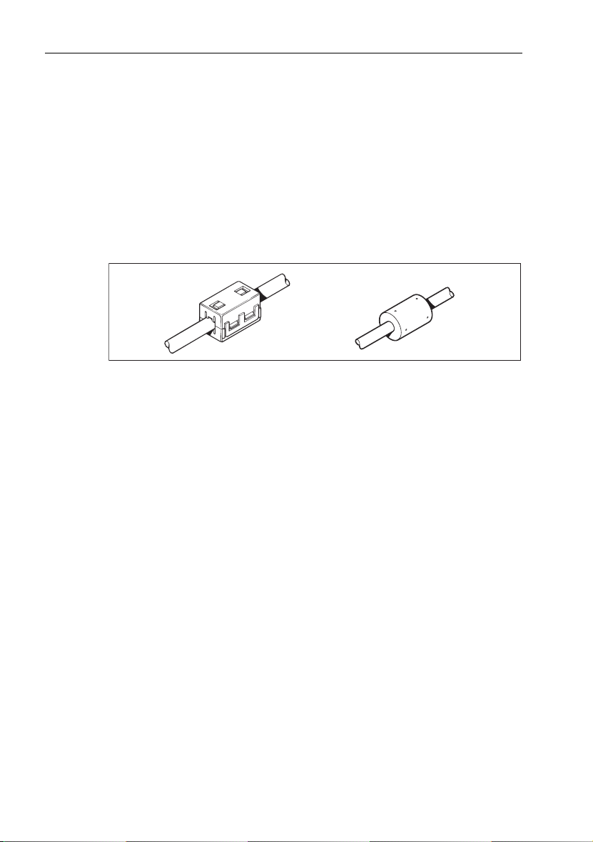
The remainder of this chapter covers the connection of these units. When
complete, the core system will be connected like this:
The SmartPilot system
Key components
SmartPilot
Controller
Fluxgate
compass
1
SmartPilot
computer
Drive
unit
Rudder
position sensor
D6403-1
Page 12

2 SmartPilot Series Commissioning Guide
1.2 The SmartPilot computer
The SmartPilot computer lies at the heart of the autopilot system. It processes
information from the sensors in the system so it can steer the boat using the drive
unit:
• it contains a microprocessor and electronic circuitry to control the drive unit
and the drive motor.
• it is the central distribution point for the autopilot system, with terminals to
take power from the boat’s distribution panel and inputs/outputs for all other
autopilot components
• it has inputs/outputs for SeaTalk and NMEA so you can connect it to Raymarine and other manufacturer’s equipment.
SmartPilot types
S1G, S2G and S3G Smartpilots have a built-in yaw sensor (Gyro) which measures
the boat’s rate of turn. This information is used to enhance course keeping in
adverse weather and sailing conditions.
Non-G systems do not contain a built-in Gyro. These can be upgraded with a
dealer-fitted internal Gyro or connecting an external Gyro unit.
SmartPilot
Version
S1G 12 V All Raymarine Type 1 12 V drives and pumps
S1 12 V All Raymarine Type 1 12 V drives and pumps
S2G 12 V All Raymarine Type 1 12 V drives and pumps
S2 12 V All Raymarine Type 1 12 V drives and pumps
S3G 12 V or 24 V All Raymarine 12 V and 24 V Type 1, Type 2 and
S3 12 V or 24 V All Raymarine 12 V and 24 V Type 1, Type 2 and
Volvo
Penta IPS
(S3G)
Supply
voltage
12 V or 24 V Only to be used with Volvo Penta IPS Drive sys-
Drive unit compatibility Built-in
(excluding 12 V Constant Running pump).
(excluding 12 V Constant Running pump).
(including 12 V Constant Running pump).
(including 12 V Constant Running pump).
Type 3 drives and pumps. Drive voltage must be
matched to boat’s supply voltage.
Type 3 drives and pumps. Drive voltage must be
matched to boat’s supply voltage.
tems.
Gyro?
Yes
No
Yes
No
Yes
No
Yes
Page 13
Chapter 1: System Connections 3
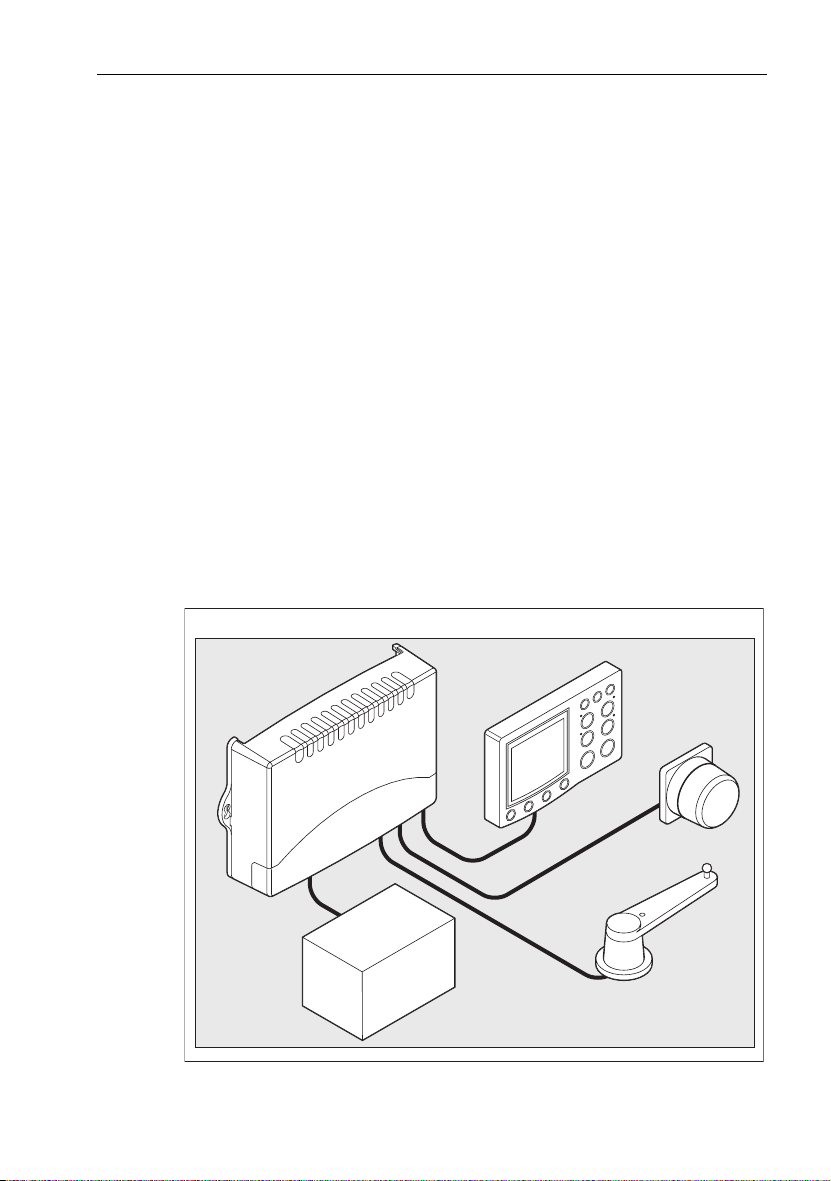
1.3 Removing and replacing the connector cover
WARNING: Electrical safety
Before you make any electrical connections, ensure the power
supply is switched off and you have read the EMC installation
guidelines (see
S1 Systems S2 and S3 Systems
page iii
.)
• hold the bottom of the connector cover
• gently lift the connector cover away from
the base and the lid will come free
To open
PULL
D6385-1
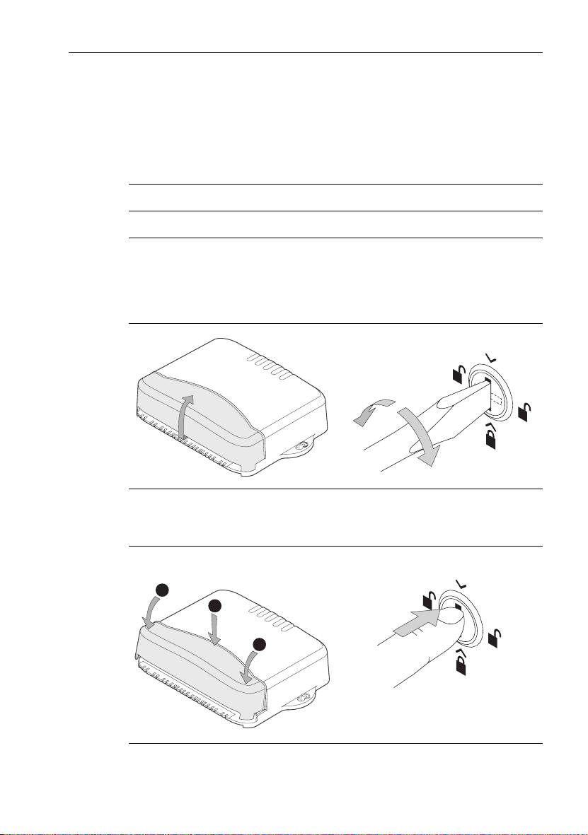
• replace the cover
• gently press the sides of the cover until
you hear it click
To close
2
1
2
• use a flat-bladed screwd river or small coin
to rotate the catch
1
/4 turn (90°) in either
direction – until you hear a click and the
slot is horizontal
• lift off the cover
To open
D6387-1
• replace the cover
• turn the catch so the slot is vertical
• push in the catch until you hear it click
To close
D6386-1
D6388-1
Page 14
4 SmartPilot Series Commissioning Guide
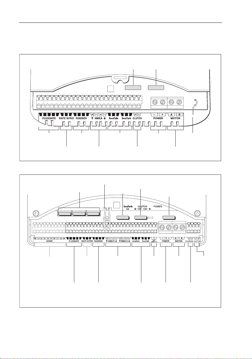
Computer inputs, outputs and fuses
S1 Systems
Fluxgate
compass inputs
S2 and S3 Systems
Rudder position
sensor inputs
External GyroPlus
yaw sensor inputs
Spare fuses
NMEA 0183
input/ouput
Fuse puller
SeaTalk fuse
SeaTalk
inputs/outputs
SeaTalk fuse
(5 A)
(2 A)
SEATALK
Drive clutch
ouputs
Clutch fuse
(4 A)
Power fuse
(15 A)
POWER IN
Power
inputs
(12 V)
Note: Spare fuses located
in the connector cover
Drive motor
outputs
Power fuse
S2: 30 A
S3: 40 A
RF GND
RF ground
connection
D6389-1
Spare connectors
(S3 only)
Fluxgate
compass
inputs
External
GyroPlus
yaw sensor
inputs
sensor inputs
Rudder
position
NMEA 0183
inputs/outputs
SeaTalk
inputs/
outputs
Off switch
inputs
Power inputs
S2: 12 V
S3: 12 V or 24 V
Drive
motor
outputs
Drive solenoid
return inputs
(for drives/pumps
with solenoids)
Drive clutch
outputs
S3:
selectable for
12 V or 24 V
D5193-2
Page 15

Chapter 1: System Connections 5
1.4 Connecting the Power and the Drive unit
CAUTION:
Use of incorrect power cable size could cause your SmartPilot to
malfunction and will reduce the power supplied to the drive unit.
Ensure the correct size is used and if in doubt, use a heavier gauge
cable.
Note:
For Volvo Penta IPS autopilot systems a moto r connection is not required. F or more
information, please refer to the Connections guide supplied with the DPU.
To connect the power and motor connections, follow the steps below:
1. Measure the total length of cable run from the boat’s distribution panel to the
SmartPilot computer.
2. Select the appropriate size cable (distribution panel to SmartPilot computer):
Cable length S1 S2 & S3Cable
gauge
Type 1 drive 12/24 V;
I/O drive;
Volvo Penta IPS system (S3G);
CR pump solenoids*
up to 3m (10ft)
¸
¸
¸
¸
¸
¸
¸
14 AWG
12 AWG
10 AWG
8 AWG
up to 5m (16ft)
up to 7m (23ft)
up to 10m (32ft)
Type 2 drive 12 V
up to 5m (16ft)
up to 7m (23ft)
Type 2 drive 24 V
up to 3m (10ft)
up to 5m (16ft)
up to 10m (32ft)
Type 3 drive 12 V
up to 5m (16ft)
Type 3 drive 24 V
up to 5m (16ft)
up to 7m (23ft)
¸
¸ 10 AWG
8 AWG
¸
¸
¸
12 AWG
10 AWG
8 AWG
¸
8 AWG
¸
¸ 10 AWG
8 AWG
Copper
area
2.5 mm
2
4 mm
2
6 mm
2
10 mm
2
6 mm
2
10 mm
2
4 mm
2
6 mm
2
10 mm
2
10 mm
2
6 mm
2
10 mm
2
Note:
* These specifications apply to the cabling for CR
motor
separately, as specified in the CR pump installation guide.
solenoids
. Power the CR pu mp
Page 16
6 SmartPilot Series Commissioning Guide
3. Select the appropriate circuit breaker or fuse:
Drive unit S1 S2 & S3Fuse Thermal over-current
circuit breaker
Rotary, linear, hydraulic pump,
hydraulic linear
Type 1: 12 V
Type 1: 24 V
Type 2: 12 V
¸¸
¸
¸
¸
¸
25 A
25 A
40 A
30 A
40 A
20 A
20 A
30 A
30 A
30 A
Type 2: 24 V
Type 3: 12 V and 24 V
I/O drive ¸ ¸ 15 A 10 A
CR pump solenoids
¸ 10 A 10 A
Volvo Penta IPS system (S3G)
4. Route the cables back to the SmartPilot computer.
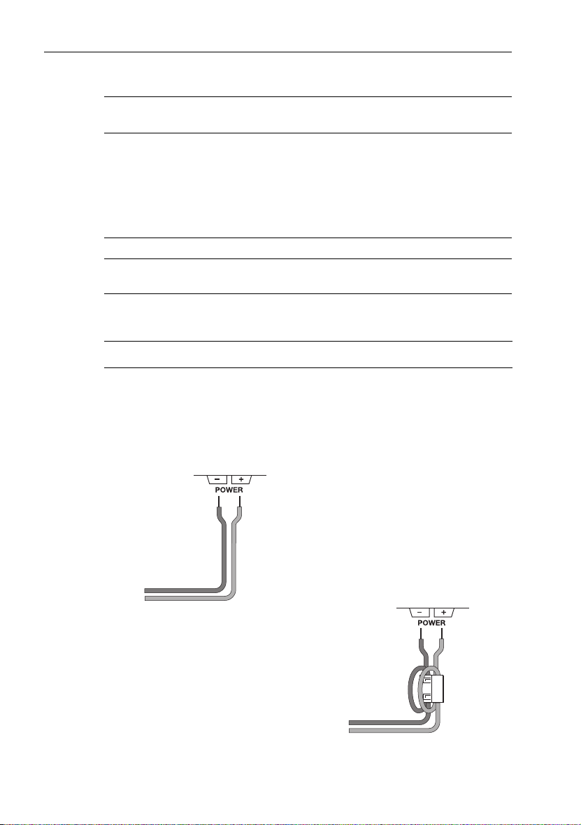
5. Connect the cables to the POWER inputs.
S1 Systems S2 & S3 Systems
• Strip 8–10 mm (½ in) of insulation from
the end of each cab le.
• Use a small screwdriver to loosen the
screw on the terminal block.
• Insert the stripped cable into the terminal
and tighten the screw.
D6390-2
• Strip 8–10 mm (½ in) of insulation from
the end of each cable.
•For the POWER connection:
Attach the suppression ferrite (supplied)
around both the positive and negative
power cables, between the cable clamp
and SmartPilot computer.
When you attach the ferrite, you must
loop both power cables so that the ferrite
encloses two passes of each cable.
Secure the ferrite with the small tie-wrap.
• Use a small screwdriver to loosen the
screw on the terminal block.
• Insert the stripped cable into the terminal
and tighten the screw.
Ferrite
D6391-2
Page 17
Chapter 1: System Connections 7
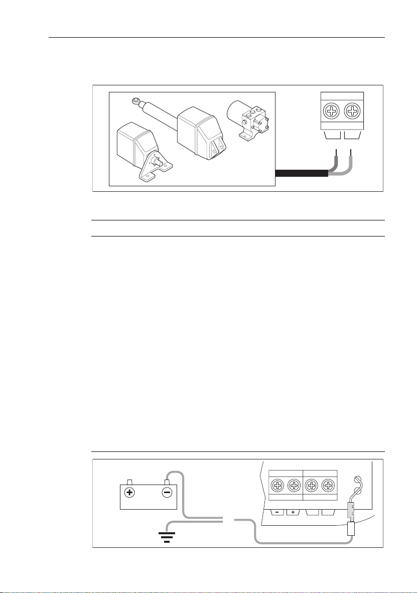
6. Connect the drive cables to the MOTOR inputs. These cables can be connected any way round as their orientation is verified later in the process.
AB
MOTOR
D6392-1
Grounding the SmartPilot
S1 Systems S2 & S3 Systems
CAUTION:
S1 systems MUST be connected to
ships ground.
Failure to connect the SmartPilot to ships
ground may cause it, or other on-board
electronics to function incorrectly.
• Us e f l at t i n n ed c o p p er b r a id , 3 0 A ra t i n g (¼
in) or greater. Equivalent stranded wire
diameter 4mm or greater.
• Using the supplied yellow (¼ in) female
spade connector, connect the braid to
RF GND on the SmartPilot computer.
• The other end of the earth strap should be
connected to metal in contact with the
water. If this is not possible, it can be connected to the negative pole of the battery
(ideally at the battery itself).
• Keep the length of the earth strap as short
as possible
S1 systems only
CAUTION:
S2 & S3 systems MUST NOT be
connected to ships ground.
If the installed location has a metallic surface, you must insulate the base of the
computer so it is not earthed.
RF GND
OR
POWER
AB
MOTOR
D6378-1
Page 18
8 SmartPilot Series Commissioning Guide
1.5 Fuse Protection
The POWER and SeaTalk terminals are fuse protected against short-circuits
and misconnections.
Your SmartPilot computer is supplied with spare fuses. The fuses used in the
computer are standard automotive blade fuses, so replacements are easily
available. Your Raymarine dealer can also provide a replacement fuse pack.
1.6 How to connect SmartPilot system elements
All SmartPilot computer terminals will accept stranded cable up to 2.5 mm
(14 AWG).
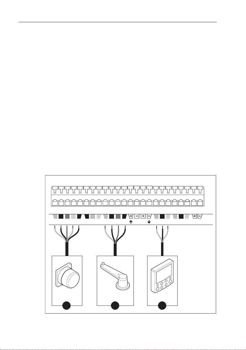
Connect the following elements as shown in the diagram:
1. Compass
2. Rudder Sensor
3. SmartPilot Controller via SeaTalk
Note:
For Volvo Penta IPS autopilot systems a rudder sensor is not required. For more in-
formation, please refer to the Connections guide supplied with the DPU.
SmartPilot computer terminals
2
Red Yellow
Screen Blue
Green Screen
Compass
Red Yellow
Screen
External
Rate Gyro
(Optional)
Rudder sensor
BlueRed
Green
Output (Optional)
1 2 3
NMEARUDDERRATE GYROFLUXGATE
NMEA
Input and
Red
YellowScreen
Controller
YellowScreen
Red
SeaTalkSeaTalk
CLUTCH
Clutch
(Linear, Rotary
& I/O drives only)
D6307-1
Page 19
Chapter 1: System Connections 9
Securing the Cables
1. Strip at least 5 mm (¼ in) of insulation from the end of each cable
2. Use a small screwdriver to push the small plastic lever on top of the terminal
and release the cable clamp
3. Insert the stripped cable and release the lever to grip the cable
1.7 How to connect SeaTalk equipment
Note:
For Volvo Penta IPS autopilot systems, please refer to the Connections guide sup-
plied with the DPU.
You can use SeaTalk to connect your SmartPilot to:
• additional SeaTalk controllers: you can use any controller to operate the
SmartPilot and view autopilot information
• SeaTalk equipment (such as instruments, chartplotters, radar and GPS):
• the SmartPilot can use information from this equipment to enhance
course keeping and provide additional features.
• you can also display information from the SeaTalk equipment on the
SmartPilot controller.
The following illustrations show some typical ways to connect simple SeaTalk
systems.
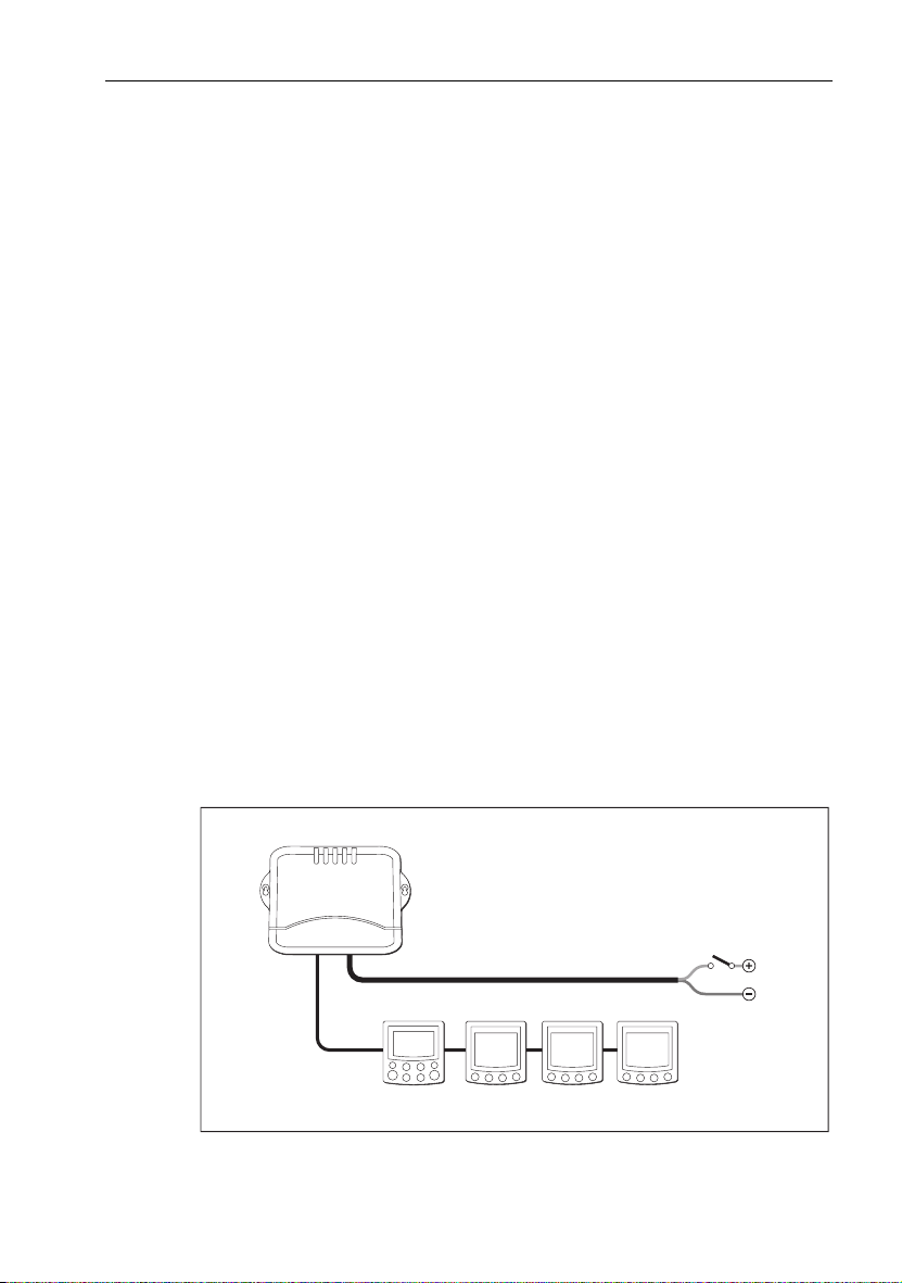
Single control unit, single power supply
The simplest type of system has the SmartPilot computer providing power to a
single SeaTalk bus that includes a single controller and several instruments.
Single control unit, single power supply
Course computer
power supply
(via breaker/fuse)
SeaTalk
SmartPilot
computer
SmartPilot
controller
SeaTalk bus
SeaTalk instruments
D6300-1
Page 20
10 SmartPilot Series Commissioning Guide
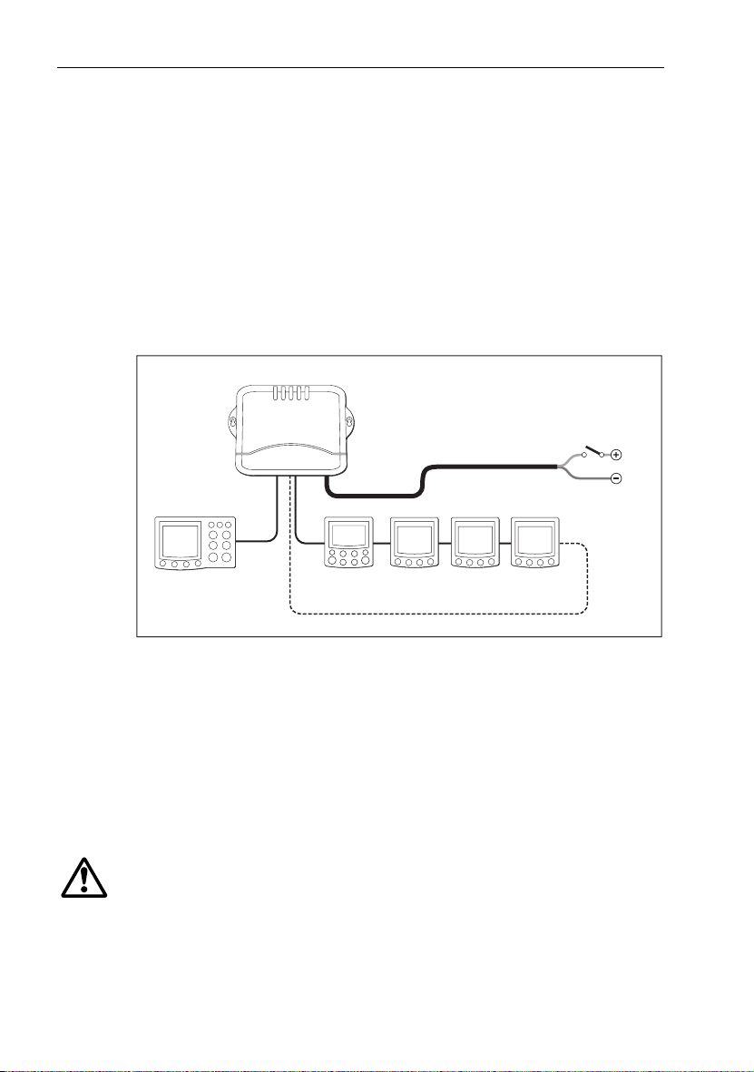
Isolated control unit, single power supply (S2 and S3
computers only)
If you have two control units, we recommend that you connect one to each
SeaTalk terminal. In the following illustration:
• the SmartPilot computer provides power to the SeaTalk system
• one control unit is connected on its own to SeaTalk A so it is isolated against
any possible failure of SeaTalk B
If the SeaTalk B line fails, the isolated control unit will switch to Standby mode as
a safety measure. By pressing
autopilot control.
Isolated control unit, single power supply
SeaTalk A
auto on the isolated control unit you can regain full
Course computer
power supply
SmartPilot
computer
SeaTalk B
SeaTalk bus
(via breaker/fuse)
Isolated
control unit
Note:
Depending on the number of SeaTalk units and the total length of SeaTalk cabling,
Second
control unit
Extra connection on larger SeaTalk systems
ST60 instruments
D6383-1
you may need to provide12 V power supply to each end of the SeaTalk bus (‘ring-main’
style). Refer to the instrument handbook for more information.
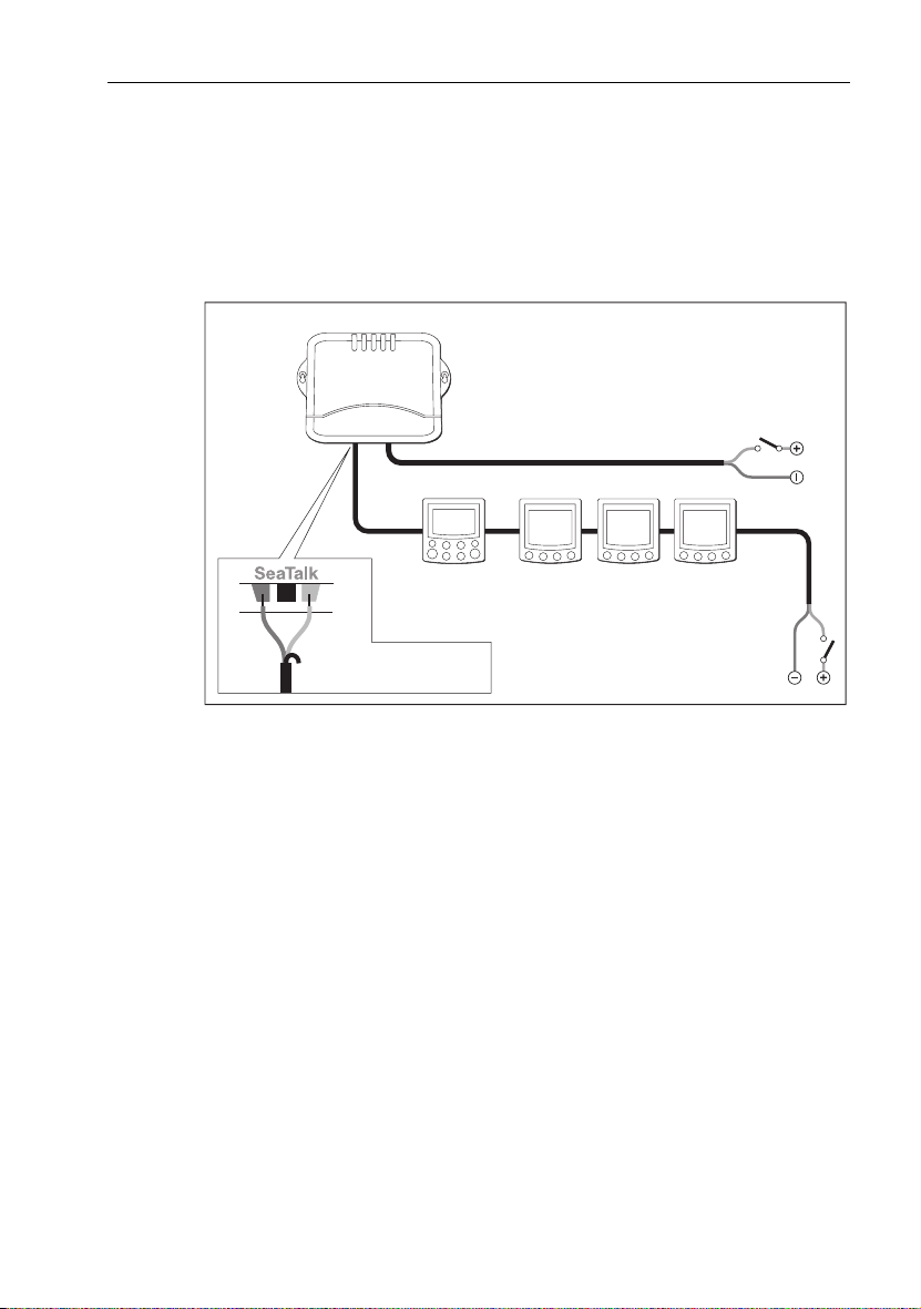
Separate SmartPilot computer and instrument power
Another option is to provide separate power supplies to the SmartPilot computer
and SeaTalk system so you can have independent, switched instrument and pilot
systems.
Note:
DO NOT connect the SeaTalk RED wire at the SmartPilot terminal
WARNING: Use correct fuse
The fuse supplying the instrument system MUST be rated at 5A or
less.
The behavior of the computer and the instruments now depend on where power
is applied to the system.
Page 21
Chapter 1: System Connections 11
• Computer AND instrument power supplies ON:
The system will function normally.
• Only computer power supply ON:
The controller and instruments do not power up.
• Only instrument power supply ON:
The controller shows a PILOT OFF or NO LINK message.
Separate SmartPilot computer and instrument power supplies
Computer
SmartPilot
computer
SeaTalk bus
SeaTalk
power supply
(via breaker/fuse)
SeaTalk
SeaTalk instruments
Instrument SeaTalk
bus 12 V power supply
(via breaker/fuse
rated at 5 A or less)
D6302-2
Screen
SmartPilot
controller
Yellow
Do not connect Red wire
(Cut back and insulate)
Connecting SeaTalk or NMEA compasses
You can connect SeaTalk or NMEA compasses to the SmartPilot computer, either
to replace the fluxgate compass or provide supplementary compass signals.
When you connect more than one compass to the autopilot system, the computer
processes their signals in this order of priority:
1. Fluxgate compass
2. NMEA compass
3. SeaTalk compass
This means that if you want to use a NMEA compass as the primary compass, you
need to disconnect the fluxgate compass.
To connect a SeaTalk or NMEA compass to the autopilot system:
• NMEA compass: connect it to a NMEA input on the computer
• SeaTalk compass: connect it to the SeaTalk bus or the SeaTalk terminals
Page 22
12 SmartPilot Series Commissioning Guide
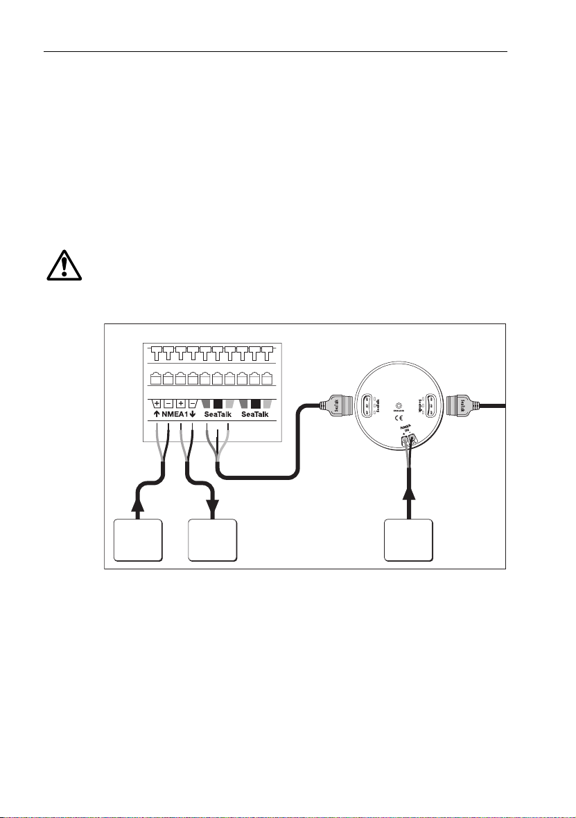
1.8 How to connect NMEA equipment
If you have equipment on your boat that transmits or receives NMEA 0183 data
(e.g. GPS), you can connect this equipment to the SmartPilot. NMEA equipment
can be connected in any combination of these ways:
• using the SmartPilot computer NMEA input/output
• using the NMEA input on the back of the SmartPilot controller. (Refer to the
Controller handbook for NMEA data details)
• using the SeaTalk/NMEA interface (part number: E85001) to convert the
NMEA data to SeaTalk data
WARNING: Connections to other equipment
If you are connecting Raymarine equipment to other equipment
using a non-Raymarine cable, you MUST attach an appropriate
suppression ferrite to the cable near to the Raymarine unit.
SmartPilot computer terminals
Controller (rear)
SeaTalk
Red
NMEA NMEA
GPS
Other
Instrument
Screen
NMEA
radar
Yellow
SeaTalk
NMEA
NMEA
instrument
D6303-1
Page 23

Chapter 1: System Connections 13
SmartPilot computer NMEA inputs/outputs
Note:
Do NOT connect more than one piece of equipment to each SmartPilot computer
NMEA input.
NMEA connectivity overview
S1 Systems S2 & S3 Systems
The S1 has a single NMEA input/output to
receive and transmit information from
NMEA equipment.
SmartPilot computer NMEA inputs
NMEA 0183
received
APB ¸ ¸ cross track error, bearing to waypoint, waypoint
BWC
BWR
GGA
GLL
HDG
HDM
HDT
MWV ¸ ¸ apparent wind angle, apparent wind speed
RMA ¸ ¸ course over ground (COG), speed over ground
RMB ¸ ¸ cross track error, bearing to waypoint, distance to
RMC ¸ ¸ course over ground (COG), speed over ground
VHW ¸ ¸ speed through water, heading
VTG ¸ ¸ course over ground (COG), speed over ground
VWR ¸ ¸ relative apparent wind angle, relative apparent
XTE ¸ ¸ cross track error
ZDA ¸ ¸ time, date
Note:
When connected to a NMEA navigator, S2 & S3 systems look at NMEA 1 first. If
S1 S2 &S3Information extracted
¸
¸
¸
¸
¸
¸
¸
¸
¸
¸
¸
¸
¸
¸
S2 and S3 systems have two sets of NMEA
inputs/outputs to receive and transmit
information from NMEA equipment.
number
bearing to waypoint, distance to waypoint, waypoint number, time
latitude/longitude, time
heading
(SOG), latitude/longitude, variation
waypoint, waypoint number
(SOG), latitude/longitude, time, variation
(SOG)
wind speed
NMEA 1 has no data, it then looks at NMEA 2. If both channels have the same type of navigation data, NMEA 1 is used.
Page 24

14 SmartPilot Series Commissioning Guide
SmartPilot computer NMEA outputs*
NMEA 0183
sent
BWC ¸ 2 bearing to waypoint*, di stance to waypoint*,
GLL ¸ 2 latitude/longitude*, time*
HDG
HDM
HDT
VTG ¸ 2 course over ground* (COG),
* Note: The computer will only transmit these items if it has received the appropriate
data.
S1 S2 & S3
(NMEA port)
¸
2
¸
1 & 2
¸
2
Information sent
waypoint number*, time*
heading
speed over ground* (SOG)
Notes: (1)
S1G systems provide fast heading (HDM) output at 5 Hz 0.1º resolution
(2)
S2G & S3G computers provide fast heading (HDM) output at 10 Hz 0.1º
resolution.
This fast heading data is suitable for use with the MARPA function on radar
equipment.
(3)
In Volvo Penta IPS systems, NMEA port 1 is reserved for connection to the
DPU, NMEA port 2 remains available for general purpose NMEA
connections. For more information, please refer to the Connections guide
supplied with the DPU.
1.9 How to connect optional components
Note:
For installation, refer to the guide supplied with the component.
GyroPlus yaw sensor
Non-G SmartPilots do not contain a built-in Gyro, but you have the option of
adding:
• an external GyroPlus (part number: E12101)
• or a dealer-fitted internal GyroPlus (part number: A18069)
Handheld remotes
Two wireless Raymarine handheld remote control systems are available:
• the Smart Controller system can act as the sole pilot controller in your system
or as a full-function remote for systems with other fixed pilot controllers.
• the compact S100 Controller system gives you full course control away from
the main steering position
Page 25
Chapter 1: System Connections 15
External alarm
The SmartPilot sounds all critical alarms from all controllers. On large or noisy
boats you can fit a Raymarine external alarm (part number: Z035, connected
through E85001 interface box) as a high volume audible repeater.
Wind vane (sail boats)
The SmartPilot computer can use wind angle information from a wind vane or
instrument to maintain a course relative to the wind. You can provide wind angle
information to the autopilot system by connecting it to a suitable SeaTalk or
NMEA instrument (providing wind angle and speed information)
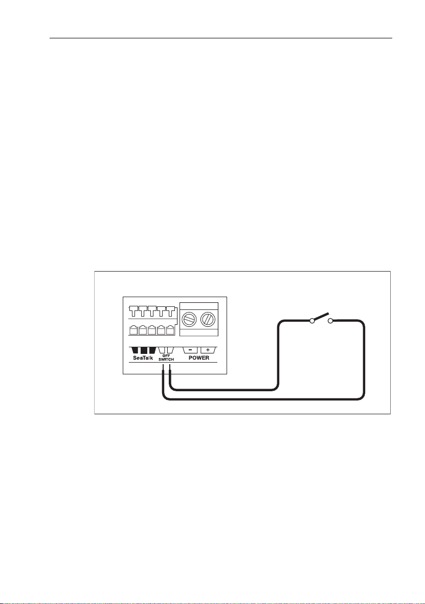
Off switch (S2 and S3 only)
The SmartPilot computer has inputs so you can fit an off switch if required. By
closing a circuit, this switch will turn off the computer power supply.
Connect a suitable off switch to the
Connecting an Off switch
SmartPilot computer terminals
OFF SWITCH inputs on the computer.
Off switch (closes circuit to
turn off course computer power)
Other manufacturers’ drive units (S2 and S3 only)
If you are connecting a nother manufacturer’s drive unit, refer to the specifications
(see
page 65
) for information on the SmartPilot computer’s drive motor, drive
clutch and drive solenoid terminals. Connect the drive unit to these terminals as
necessary. For more information, contact the drive unit manufacturer.
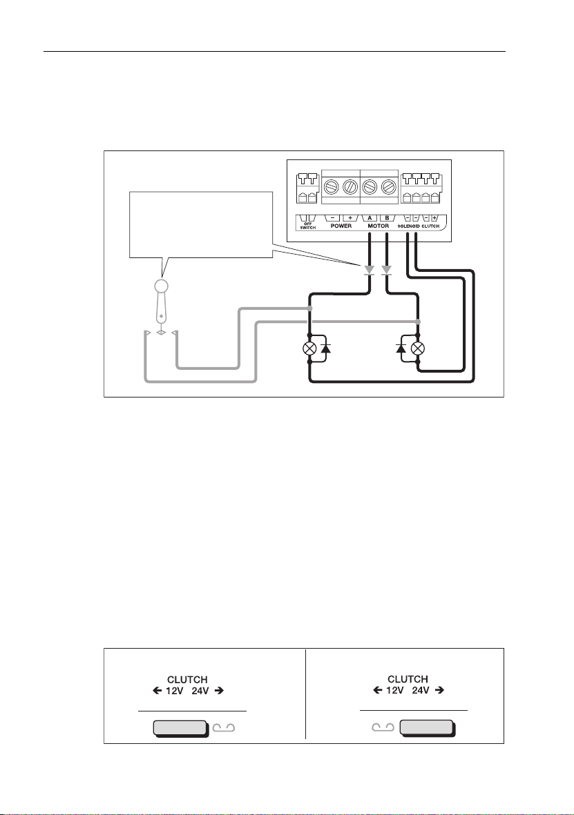
Connecting spool valves (S2 and S3 only)
If the drive has spool valves, connect them to the motor and solenoid terminals on
the computer as shown below. The computer provides a negative ground for the
spool valves even when it is switched off.
D5396-2
Page 26
16 SmartPilot Series Commissioning Guide
CAUTION:
Do NOT connect the solenoid return cables to boat’s negative
ground, as this will bypass the current protection devices inside
the SmartPilot computer.
SmartPilot S2 & S3 connections
If electronic steering or jog lever is
used on the same solenoids, fit
diodes (suggested type: 1N4004)
as indicated to prevent
backfeeding the course computer.
Return cables
Electronic steering
or jog lever
Diodes
12 V
24 V
Spool valves
(diodes across
spool valves)
D5397-3
Selecting clutch voltage (S3 & S3G only)
You can use the S3 and S3G SmartPilot computers with other manufacturers’
drives that have either 12 V or 24 V clutches. If you do this, you may have to
reposition the clutch fuse.
Important: All Raymarine 12 V and 24 V drive units with a clutch have a 12 V
clutch, so you do NOT need to re-position the clutch fuse.
If you are using another manufacturer’s drive, ascertain the operating voltage of
the CLUTCH. Ensure the clutch fuse is set to the correct voltage, i.e. to the left for
a 12 V clutch, or right for a 24 V clutch. If necessary, select the appropriate clutch
voltage by re-positioning the clutch fuse.
It is important to appreciate that the fuse position does NOT depend on the
voltage used on your boat, but on the operating voltage of the CLUTCH.
Fuse position: 12 V CLUTCH Fuse position: 24 V CLUTCH
4
4
D5398-3
Page 27

Chapter 1: System Connections 17
1.10 Secure the cables
S1 systems
To prevent strain on the connector blocks, secure the cables to the SmartPilot
computer with cable ties as shown below.
SmartPilot
D6321-1
S2 and S3 systems
When you have connected all autopilot system components, we recommend that
you use the supplied cable clamp to relieve any strain on the cable connections.
Referring to the illustrations below, secure the cables with the cable clamp as
follows:
1. Hold the cable clamp in place below the computer, making sure:
• its center hole is below the center o f the computer (i.e. in line with the connector cover catch)
• it is at least 50 mm (2 in) from the bottom of the computer
• the hole locations are clear of any cables
2. Mark the position of the three holes, then remove the cable clamp.
3. Drill the three pilot holes using a 3 mm (
1
/8 in) drill bit.
Page 28

18 SmartPilot Series Commissioning Guide
D6380-1
4. Secure the cable clamp using the self-tapping screws supplied
3
(No 8 x
• the tie-wrap securing loops are on the right (below the
/4in, pan-head), making sure:
POWER and
MOTOR terminals on the computer)
• the clamp securely holds all cables
• the legs on cable clamp do not pinch any of the cables
1 2
D6381-1
Note:
If the power and/or mot or cables are larger than 5 mm (1/4 in) diameter, se cure them
on top of the ca ble clamp with the tie-wra p supplied. Make sure the t ie-wrap sits above the
cables (as shown below), so it pulls the cables against the clamp when tightened.
Page 29

Chapter 2: SmartPilot Commissioning
This chapter will guide you through the commissioning process for your
Raymarine autopilot. This comprises a series of dockside safety checks followed
by a short seatrial calibration.
WARNING: Calibration requirement
All autopilot systems must be calibrated before use.
SmartPilot Controller Compatibility
This SmartPilot system can be commissioned using any of the available SmartPilot
controllers. There are some differences in the method of control and these are
defined in the table below.
ST6001 & ST6002
Controller
ST7001 & ST7002
Controller
ST8001 & ST8002
Controller
19
D6400-1
• standby & auto
function keys
• +1, -1, +10 & -10 course
change keys
• disp & track extended
function keys
2.1 Dockside Checks
WARNING: Ensure safe control
For safe control of your boat, you MUST complete the dockside
checks before starting the initial seatrial.
With the boat safely tied up, complete the following dockside checks:
• standby & auto
function keys
• +1, -1, +10 & -10 course
change keys
• resp, track, mode,
res’m, disp, up &
down extended function
keys
D6401-1
• standby & auto
function keys
• Rotary course change
control
• resp, track, mode,
res’m, disp, up &
down ex tended function
keys
D6402-1
Page 30

20 SmartPilot Series Commissioning Guide
Step 1 - Switch on
1. When you have installed your SmartPilot system, switch on the main power
breaker.
2. If the SmartPilot controller and computer are active, the controller will beep,
show the controller type for a few seconds will show the STANDBY
screen.You may see a CALIBRATE REQUIRED message. This is displayed
for a short time if either:
• the vessel type is not selected
• the compass is not calibrated
These will be calibrated later in this chapter.
3. Check that the STANDBY screen displays a live compass heading and a rudder angle.
TRUE
D3561-6
Troubleshooting
• If the SmartPilot controller does not beep or the display is blank, check the
fuse/circuit breaker and the SeaTalk fuse in the SmartPilot computer.
• If the display shows the SEATALK FAIL or NO DATA alarm message,
check the SeaTalk connections.
•If the STANDBY screen does not display a live compass heading or a rudder
angle, check the sensor connections.
Step 2 - Check the SeaTalk and NMEA connections
SeaTalk connections
If you have connected the SmartPilot controller to other existing SeaTalk
instruments or controllers, check the links as follows:
1. Select display lighting level 3 (LAMP 3) on one of the other SeaTalk instruments or controllers.
2. The SmartPilot should immediately switch on its display lighting:
• if the lighting does not switch on, check the SeaTalk cabling between the
SmartPilot and the other units.
Page 31

Chapter 2: SmartPilot Commissioning 21
NMEA navigator connections
If you have connected the SmartPilot to a NMEA navigator, check the links by
displaying the default navigation data pages on the SmartPilot controller:
• press disp to display the first data page (XTE), and check that this page
shows the expected data.
• press disp again to check each successive data page (BTW, DTW etc)
If the display shows dashes instead of data values, check for the following:
• the navigator is not switched on or not transmitting an active waypoint
• a cabling error. Check for open circuit, short circuit or reversed wires
• the navigator is not configured to transmit the required data format
Wind instrument connections
• If you have connected the SmartPilot to a NMEA or SeaTalk wind instrument,
check the links by pressing standby and auto together:
• the SmartPilot should display the Wind Vane mode screen, with the locked
wind angle and locked heading.
+
MAG
• if the controller does not display WIND mode, the SmartPilot is not receiving
wind data. Check the wind instrument and connections.
Step 3 - Check the autopilot operating sense
Check the rudder position sensor
1. Turn the wheel manually to starboard.
2. Check that the rudder bar on the controller moves to starboard.
If the rudder bar display moves the wrong way:
i. turn off the power
ii. reverse the red and green wires connected to the RUDDER inputs on the
SmartPilot computer
iii. switch on the power and re-check
D3565-6
Page 32

22 SmartPilot Series Commissioning Guide
Check the autopilot steering sense
1. Manually center the wheel, then press the auto key so the SmartPilot is in
Auto mode.Check that the display shows AUTO.
Be ready to press standby if the rudder moves hardover.
2. Press the +10 key once or turn the rotary control ½ turn clockwise.
ST6001
ST7001
ST6002
ST7002
ST8001
ST8002
½ turn
D6341-2
3. Check that the rudder moves to starboard a few degrees and then stops.
• if the rudder drives hardover, immediately press standby to prevent fur-
ther rudder movement
4. If the rudder moves to port or the rudder drives hardover:
i. press standby
ii. turn off the power
iii. reverse the motor wires connected to the SmartPilot computer
iv. switch on the power and re-check
Note:
If the rudder overshoots and has to drive back or starts to hunt back and forth, you
will need to increase the rudder damping level manually (See page 50).
Step 4 - Adjust key SmartPilot settings
The next step in the commissioning process requires the adjustment of some key
settings. To achieve this you will need to enter one of the four calibration modes,
Dealer Calibration. For more information on the various calibration modes and
their uses see
Chapter 3, Adjusting Settings
.
Page 33

Chapter 2: SmartPilot Commissioning 23
Enter Dealer Calibration mode
As improper use of the Dealer Calibration settings can seriously impair SmartPilot
performance, we have made entry to the Dealer Calibration mode more difficult.
Ensure you follow the instructions in this step carefully.
1. Start with the SmartPilot in STANDBY mode.
2. Enter DEALER CAL as follows:
ST6001/ST6002 Controllers ST7001 /ST7002 and ST8001/ST8002
Controllers
• press and hold the standby key for two
seconds to enter the Calibration mode
• when the screen shows
press the disp key until you see the
DEALER CAL screen
•press the auto key: the display will
change to
•press -1 and +1 together to enter Dealer
Calibration mode
Note:
At the CAL ? screen, press + together to enter DEALER CAL
CAL?
For more information on SmartPilot settings, refer to Chapter 3:
2 sec
DISPLAY CAL,
x3
-1 +1
or
+
• press and hold the standby key for two
seconds to enter the Calibration mode
• when the screen shows DISPLAY CAL,
press the disp, up or down arrow
key until you see the DEALER CAL
screen
• press the auto key: the display will
change to
•press -1 and +1 together (ST7001/
ST7002) or press up and down arrow
keys together (ST8001/ST8002)
to enter Dealer Calibration mode
(ST8001 & ST8002 only)
CAL?
D6322-2
Set the vessel type
When you select a vessel type, the SmartPilot automatically selects appropriate
default values for various other calibration settings.
Some of these settings will be checked later in this procedure and the remained
should not require any adjustment. The default values for each vessel type are
listed on
page 57
.
Page 34

24 SmartPilot Series Commissioning Guide
To set the vessel type:
1. Use the disp key to scroll through the Dealer Calibration pages until the display shows either VESSEL or one of the vessel types (e.g. DISPLACE).
2. Use the -1 or +1 keys or the rotary control to select your vessel type:
Options
DISPLACE
SEMI DISPLACE
PLANING
STERN DRV
WORK BOAT
SAIL BOAT
Power-driven boats which do not plane
(Typically below 15 kts top speed)
Faster power-driven boats which do not plane
(Typically 15-20 kts top speed)
Planing boats with inboard engine(s) and shaft drives
(NOT boats with outdrives)
Boats with outdrives or outboard engines
Commercial tugs, fishing vessels, etc
Sailing boat
3. Press disp to select the new type of boat and move to the next calibration
option.
Page 35

Chapter 2: SmartPilot Commissioning 25
Set the drive type
SmartPilot systems are designed to operate with a wide range of steering drives.
Use this calibration setting to select the fitted drive type.
1. With the SmartPilot still in Dealer Calibration, use the disp key to scroll
through the calibration pages until you reach the DRIVE TYP page.
2. Use the -1 or +1 keys or the rotary control to select the appropriate drive
type:
Drive Drive Type Setting
Drive Type 3
•Linear
•Rotary
Typically found on yachts
•I/O (stern)
D6404-1
Found on Powerboats
Drive Type 4
•Hydraulic reversing pump
Used on yachts and powerboats with
hydraulic steering
D6405-1
Drive Type 5
•Constant running hydraulic pumps. Controlled by solenoid valves
Found on light commerci al and larger boats
(S2 and S3 systems only)
D6406-1
3. Press disp to select the drive type and move to the next calibration option.
Page 36

26 SmartPilot Series Commissioning Guide
Align the rudder position sensor
1. With the SmartPilot still in Dealer Calibration, press the disp key to scroll
through the calibration pages until you reach the ALIGN RUD page.
2. Center the rudder using the wheel.
3. Use the -1 and +1 keys or the rotary control to adjust the rudder bar so it
reads at center.
• the maximum adjustment available is ±9° for S1 systems, and ±7° for S2
& S3 systems. If the offset is beyond these limits, you will need to physically adjust the alignment of the sensor.
4. Press disp to select the correct alignment and move to the next calibration
option.
Note:
Alternatively, you can zero the rudder bar with the boat underway during the initial
seatrial, by manually steering a straight course then accessing the
in Seatrial Calibration to adjust the offset.
ALIGN RUD
screen
Set the rudder limits
1. With the SmartPilot still in Dealer Calibration press the disp key to sc roll
through the calibration pages until you reach the RUD LIMIT page.
2. Turn the wheel to move the rudder:
• to the port end stop and note the angle on the rudder bar
• to the starboard end stop and note the angle on the rudder bar
3. Use the -1, +1, -10 and +10 keys or the rotary control to set the rudder
limit to 5° less than the lowest angle you have noted.
4. Press disp to select the new value and move to the next calibration option.
Save the new settings
When you have adjusted these basic settings in Dealer Calibration:
• press and hold standby for two seconds, your changes will be saved
• once saved, the controller will return to the STANDBY display
Page 37

Chapter 2: SmartPilot Commissioning 27
2.2 Seatrial Calibration
When you have completed the dockside calibration, you must complete
SmartPilot setup by taking the boat on a short seatrial to:
1. Calibrate the compass:
• complete the automatic deviation correction
• align the compass heading
2. Adjust SmartPilot settings to suit your boat:
• automatically on S1G, S2G and S3G systems
• manually on Non-G systems
To achieve this you will need to enter another of the four calibration modes,
Seatrial Calibration. For more information on the various calibration modes and
their uses see
Seatrial safety
CAUTION: EMC conformance
Always check the installation before going to sea to make sure
that it is not affected by radio transmissions, engine starting etc.
IMPORTANT
You can return to manual steering at any time during the seatrial
by pressing the
You should only perform the initial seatrial:
• when you have successfully completed the dockside calibration
• in conditions of light wind and calm water, so you can assess SmartPilot performance without the influence of strong winds or large waves
• in waters that are clear of any obstructions, so the boat has plenty of clear
space to maneuver
Note:
ment – such as a GPS (providing course over ground (COG), speed over ground (SOG) and
latitude (LAT) data) or a speed log (providing speed through the water). This information
will help the SmartPilot achieve best performance.
page 39
.
standby key.
Before you start your seatrial, make sure you have switched on any ancillary equip-
Page 38

28 SmartPilot Series Commissioning Guide
Calibrating the compass
Note:
This section does not apply if you have connected an NMEA compass to your SmartPilot. Refer to the handbook supplied with the NMEA compass for information about calibration.
Deviating magnetic fields can cause significant compass errors on your boat. The
correction procedure reduces these errors to a few degrees, so you MUST
perform this procedure as the first item in your initial seatrial. The SmartPilot will
then automatically correct the compass.
CAUTION:
Failure to complete the deviation correction will impair your
SmartPilot’s performance on some compass headings.
The deviation correction procedure (commonly called “swinging the compass”)
involves turning your boat in slow circles so the SmartPilot can determine the
deviation and calculate any correc tion required. You must carry out this pro cedure
in calm conditions and preferably on flat water.
Initial procedure
Automatic compass deviation correction
1. With the pilot in Standby mode, enter Seatrial Calibration as follows (see the
following illustration):
• press and hold standby for two seconds to enter Calibration mode
• when you see the DISPLAY CAL screen, press disp until you see the
SEATRIAL CAL screen
• press auto to enter Seatrial Calibration
2 sec
Note:
If you cannot access Seatrial Calibration, you need to disable the calibration lock.
x2
This can be found in Dealer Calibration (see page 47).
2. The first page in Seatrial Calibration should be the SWING COMPASS
page. If this is not the case, use the disp key to page through the Seatrial Calibration items until you see SWING COMPASS
D6318-2
Page 39

Chapter 2: SmartPilot Commissioning 29
Start turning boat
(see below)
Autopilot heading
Minimum of
2 circles
or
Turn boat in slow circles so:
• boat's speed stays below 2 knots
• each circle takes at least 2 minutes
Keep turning the boat until
you see the DEVIATION screen
3. When you are ready to start, press +1, or turn the rotary control clockwise,
to select SWING COMPASS ON. (On ST8001 & ST8002 systems, you must
then press auto to start the compass swing)
The controller will display TURN BOAT indicating the start of the calibration
process.
4. Start turning the boat in slow circles (with the boat’s speed below 2 knots).
You will need to complete at least two circles, taking at least 2 minutes to
complete each 360°:
• the display will show a TOO FAST message if you turn the boat too
quickly for the SmartPilot computer to correct the compass.
Apply less helm to turn in a larger circle
Note:
If necessary, you can quit the correction process by pressing the
If you then want to repeat the deviation correction, return to the
standby
SWING COMPASS
screen.
5. Continue slowly turning the boat until the controller beeps and displays the
DEVIATION screen. This indicates that the SmartPilot has completed the
deviation correction.
Note:
This screen shows the maximum deviation encountered over 360° (not as an east/
west value).
If the deviation figure exceeds 15° or the display shows no deviation value, the
compass is being affected by ferrous objects on your boat. You should move the
compass to a better location. Higher deviation figures are acceptable on steel
boats.
or
D6319-2
disp
.
Page 40

30 SmartPilot Series Commissioning Guide
Aligning the compass heading
1. Once the deviation is displayed, press disp to move to the Heading Alignment page (ALIGN HDG).
2. Manually steer the boat on a steady course at a speed which enables you to
hold that course.
3. If you have a GPS connected to your SmartPilot:
• increase the boat speed to more than 3 knots
• press auto: the SmartPilot will then set the heading to agree with the
COG (course over ground) heading received from the GPS
• as many factors can cause a difference between heading and COG (such
as tides and leeway affecting the boat) you must then fine-tune the heading alignment so it matches the boat’s steering compass or a known transit bearing
4. Use -1, +1, -10 and +10 ke ys or the rotary control to adjust the displayed
heading until it matches boat’s steering compass or a known transit bearing.
5. Press and hold standby for 2 seconds to exit Seatrial Calibration and save
the new compass settings.
Align the autopilot heading
Coarse adjustment: If COG is available from GPS, press to set autopilot heading to
a
Fine adjustment: If COG is not available (or after setting heading to COG),
b
align autopilot heading manually:
ST6001, ST7001, ST6002 & ST7002
COG value, then fine tune manually (see below).
or
or
ST8001 & ST8002
Autopilot heading
Steering compass
=
Known
heading
Adjust the autopilot heading so it shows the same value as the boat's steering compass
Save changes
2 sec
To:
• save deviation correction
• save heading alignment
• return to STANDBY mode
D6320-2
Page 41

Chapter 2: SmartPilot Commissioning 31
Adjusting the heading alignment
After completing the initial compass calibration, you can make further
adjustments to the alignment without having to swing the compass again.
Although the compass calibration removes most of the alignment error, small
errors (a few degrees) will probably remain.
Ideally, you should check the heading reading against a number of known
headings, plot a deviation curve, and determine the heading alignment value that
will give the lowest average alignment error. You can then enter this value on
the Heading Alignment screen, as described above.
If the average heading error is more than 5°, you should perform the compass
deviation correction procedure again, circling more slowly and in more favorable
conditions.
Adjusting SmartPilot steering settings
The next stage of the seatrial is to set key parameters that affect the SmartPilot’s
steering characteristics.
• using AutoLearn: S1G, S2G and S3G systems use AutoLearn – a self-learn-
ing calibration feature that automatically adjusts rudder gain, counter rudder
and AutoTrim to suit your boat
• manual set-up: Non-G systems will require manual adjustment – see
page 34
for instructions.
AutoLearn
WARNING: AutoLearn safety
The AutoLearn process requires a significant amount of CLEAR
SEA SPACE in front of the boat. The SmartPilot will take the boat
through a number of zig-zag maneuvers until it has acquired
enough data. These actions can result in sudden, sharp turns,
especially when the AutoLearn function is run on more
maneuverable boats. Press the
the AutoLearn and regain manual control of the boat.
Note:
For optimum AutoLearn results, please ensure that your boat’s rudder is aligned
correctly. See page 26 for more details.
standby key at any time to cancel
Page 42

32 SmartPilot Series Commissioning Guide
Wind
of clear sea space
At least 0.04 nm (100 m)
At least 0.25 nm (500 m) of clear sea space
1 minute
(approximately)
D5495-2
1. Access the AUTOLEARN screen in Seatrial Calibration:
i. from Standby mode, press standby for 2 seconds, then disp twice to
see the SEATRIAL CAL screen
ii. then press auto to enter Seatrial Calibration, and disp 4 times until you
see the AUTOLEARN page
Enter Seatrial calibration
2 sec
Prepare for AutoLearn
• steer straight ahead at cruising speed
(planing boats – just on the plane)
• head into wind and waves
x2
or
x4
CHECK!
Before proceeding, ensure
you have sufficient clear
sea space
Start
AutoLearn
AutoLearn in progress
2. Prepare to start the AutoLearn:
• power boats: steer straight ahead (rudder centered). For non-planing
boats, set a comfortable cruising speed. For planing boats set the speed so
the boat is just planing
D8641-1
Page 43

Chapter 2: SmartPilot Commissioning 33
• sail boats: with the sails down, steer straight ahead (rudder centered)
and motor the boat at typical cruising speed
• if conditions are not calm, head into the wind and waves
3. When you are ready to proceed, press +1, or turn the rotary control clockwise.(On ST8001 & ST8002 systems, you must also then press auto)
4. The screen will then show the CLEAR TO MANEUVER message. If it is
safe to continue, press auto to start the AutoLearn maneuvers:
• the boat will start a series of zig-zag turns and the display will show
LEARNING with a number to indicate the current AutoLearn stage
• this number will increase as AutoLearn progresses
• typically, the AutoLearn will be complete within 7 to 27 steps (depending
on boat characteristics and sea conditions)
Note:
If you need to cancel the AutoLearn, press the
standby
or
disp
key.
5. When the SmartPilot has finished learning, the controller will beep and will
display either LRN PASS or LRN FAIL:
• LRN PASS = AutoLearn completed successfully
• LRN FAIL = AutoLearn was not successful, so should be repeated. A fail-
ure code will also be displayed:
1 = AutoLearn has not been carried out
2 = AutoLearn failed, due to manual interruption
4 = AutoLearn failed, probably due to drive or compass failure
6. Press and hold the standby key for two seconds to store the new settings.
Boat completes AutoLearn
7 to 27
If you need to cancel the AutoLearn, press or
!
Save new settings
2 sec
AutoLearn successful
After
steps
Note: If you see a
LRN FAIL message,
press disp to return to
the AUTOLEARN screen
then repeat from Step 2
To:
• save AutoLearn calibration settings
• return to STANDBY mode
D6331-2
Page 44

34 SmartPilot Series Commissioning Guide
Your SmartPilot is now fully calibrated and ready for use.
The only additional setting you may need to adjust is the response level (see the
appropriate
SmartPilot Operating Guide
for more information).
Manual set-up: Non-G Systems
If you have a Non-G system you need to manually adjust the rudder gain, counter
rudder and AutoTrim settings, based on your observations of the boat’s
performance under SmartPilot control.
Adjust these settings when motoring your boat at cruising speed. On sail boats,
repeat if necessary under sail to optimize the SmartPilot.
Checking SmartPilot operation
Before manually adjusting any of these settings, familiarize yourself with basic
SmartPilot operation:
1. Steer onto a compass heading and hold the course steady.
If necessary, steer the boat manually for a short time to check how the boat
steers.
2. Press auto to lock onto the current heading. The SmartPilot should hold a
constant heading in calm sea conditions.
3. Use the -1, +1, -10 and +10 keys or the rotary control to see how the
SmartPilot alters the course to port and starboard.
4. Press standby to return to manual steering.
Response level
The principal method of adjusting the performance of SmartPilot systems is by
changing the response level. This is the only user adjustment you should need to
make to the SmartPilot on a regular basis. This controls the relationship between
the SmartPilot’s course keeping accuracy and the amount of helm/drive activity.
Whilst it is not necessary to set the response level at this stage, the testing of other
parameters requires the temporary adjustment of response settings.
Page 45

Chapter 2: SmartPilot Commissioning 35
Screen Text Effect on operation
RESPONSE 1
RESPONSE 2
RESPONSE 3
The SmartPilot will gradually ignore repetitive boat movements and
only react to true variations in course. This gives the best compromise between power use and course keeping
This setting provides tighter course keeping but will lead to
increased power consumption and drive unit activity
This setting provides the tightest possible course keeping.
To temporarily change the response level:
1. press -1 and +1 or resp to access the RESPONSE screen
2. use the -1 or +1 key or the up and down arrow keys to adjust the setting
3. press disp to confirm the change
Adjusting the rudder gain
Boats can vary widely in their response to helm, and by adjusting the rudder gain
you can change the SmartPilot’s steering characteristics. Rudder gain is a
measure of how much helm the SmartPilot applies to correct course errors –
higher settings mean more rudder is applied.
Complete the following test to determine whether the rudder gain is set correctly:
1. Set RESPONSE to level 2 (see above)
2. Sail your boat at cruising speed in clear water:
• you will find it easier to recognize the steering response in calm sea conditions where wave action does not mask steering performance
3. Press auto to enter Auto mode, then alter course by 40°:
• if the rudder gain is adjusted correctly, the 40° course change should
result in a crisp turn followed by an overshoot of no more than 5°
• if the rudder gain setting is too high, the 40° course change will result in a
distinct overshoot of more than 5° and there may be a distinct ‘S’ in the
course (A)
Correct this oversteer by reducing the rudder gain setting
• if the rudder gain is too low, the boat’s performance will be sluggish – it
will take a long time to make the 40° turn and there will be no
overshoot (B)
Correct this understeer by increasing the rudder gain setting.
Page 46

36 SmartPilot Series Commissioning Guide
New
heading
B
Rudder gain
too low
Rudder gain
too high
rudder gain
New
heading
A
New
heading
Correct
D3262-3
To adjust the rudder gain:
1. Access the RUDD GAIN screen in Dealer Calibration.
2. Use the -1 or +1 keys or the rotary control to adjust the rudder gain.
3. Press and hold standby for 2 seconds to save the changes.
4. Press auto to check SmartPilot performance in Auto mode.
Adjusting the counter rudder
If you intend to use RESPONSE level 3 (the tightest possible course-keeping) on
a Non-G system, you will need to adjust the counter rudder.
Counter rudder is the amount of rudder the SmartPilot applies to try to prevent th e
boat from yawing off course. Higher counter rudder settings result in more rudder
being applied.
To check the counter rudder setting
1. Set RESPONSE to level 3 (see
page 35
)
2. Sail your boat at cruising speed in clear water
3. Press auto to switch the SmartPilot to Auto mode, then make a 90° course
change:
• when gain and counter rudder are both set correctly, the boat performs a
smooth continuous turn with minimal overshoot
• if the counter rudder is too low, the boat will still overshoot
• if counter rudder is too high, the boat will ‘fight’ the turn and make a
series of short, sharp turns: this results in a very ‘mechanical’ feel as the
boat changes course
Page 47

Chapter 2: SmartPilot Commissioning 37
To adjust the counter rudder:
1. Access the COUNT RUD screen in Dealer Calibration. (see
2. Use the -1 or +1 keys or the rotary control to adjust the counter rudder.
3. Press and hold standby for 2 seconds to save the changes.
4. Press auto to check the SmartPilot performance in Auto mode.
Your SmartPilot is now calibrated and ready for use.
The only additional setting you may need to adjust is the response level (see
SmartPilot Operating Guide
for more information).
page 23
)
Further adjustments (Non-G)
Over time you may need to repeat these adjustments using a range of sea
conditions and headings to achieve good overall performance.
You may also need to adjust the AutoTrim setting. AutoTrim determines how
quickly the SmartPilot applies ‘standing helm’ to correct for trim changes (caused,
for example, by changes in the wind load on the sails or superstructure, or an
imbalance of engines).
Gain experience with your SmartPilot before attempting to adjust the AutoTrim
setting. On sail boats you can only evaluate the effect of AutoTrim while under
sail.
Increasing the AutoTrim level reduces the time the SmartPilot takes to get back
onto the correct course, but makes the boat less stable:
• if the SmartPilot gives unstable course keeping and the boat ‘snakes’ around
the desired course, decrease the AutoTrim level
• if the SmartPilot hangs off course for excessive periods of time, increase the
AutoTrim level
If you need to adjust AutoTrim, go up one level at a time and use the lowest
acceptable value. The possible settings range from OFF (no trim correction) to 4
(fastest trim correction). To adjust the AutoTrim:
Access the AUTOTRIM screen in Dealer Calibration.
Use the -1 or +1 key s or t he rotary control to adjust the AutoTrim level.
Press and hold standby for 2 seconds to save the changes.
Press auto to check the SmartPilot performance in Auto mode.
Page 48

38 SmartPilot Series Commissioning Guide
Page 49

Chapter 3: Adjusting SmartPilot Settings
This chapter explains all of the calibration settings you can adjust on the
SmartPilot. You will have adjusted many of these settings when commissioning
the system, and they should not require further adjustment. Complete the
procedures described in
3.1 Calibration basics
Calibration groups
The Calibration mode has 4 main calibration groups:
Display Calibration (DISPLAY CAL)
The items in Display Calibration affect the individual controller. They are stored in
the controller and do not affect any other controllers connected through SeaTalk.
You can adjust the Display Calibration settings as often as necessary – for
example, to add or change information displayed on data pages.
User Calibration (USER CAL)
The items in User Calibration vary according to the Vessel Type you have selected
in Dealer Calibration.
You wi ll probably need to access User Calibration on a fairly regular basis to adjust
SmartPilot settings in response to changing conditions.Details on User
Calibration can be found in the
Chapter 2
before adjusting any calibration settings.
SmartPilot Controller Operation Manual.
39
Seatrial Calibration (SEATRIAL CAL)
The Seatrial Calibration group is specifically designed for use during the initial
seatrial (see
You should not need to access Seatrial Calibration during normal operation.
Dealer Calibration (DEALER CAL)
The Dealer Calibration group includes items that have a significant impact on
operation and can affect your boat’s safety.
After you have completed the initial installation and seatrial, you should not
normally need to alter the Dealer Calibration values. The items in Dealer
Calibration vary according to the Vessel Type you have selected.
page 27
of
Chapter 2
for full details).
Page 50

40 SmartPilot Series Commissioning Guide
Accessing the Calibration modes
Accessing
Calibration Modes
Calibration
Modes
2 seconds
2 seconds
(saves changes)
to enter display
calibration mode
to enter user
calibration mode
to enter seatrial
calibration mode
CAL ?
+
+
to enter dealer
calibration mode
(ST8001 & ST8002 only)
D6407-2
You can only access Calibration mode from Standby mode:
1. With the SmartPilot in Standby mode, press and hold the standby key for 2
seconds. The display will change to show DISPLAY CAL.
2. Press the disp key to scroll through the 4 calibration groupings:
• Display Calibration (DISPLAY CAL)
• User Calibration (USER CAL)
• Seatrial Calibration (SEATRIAL CAL)
• Dealer Calibration (DEALER CAL)
Note:
You can go backwards thr ough the groups by pressing and holding th e
disp
key for
one second.
3. When you reach the Calibration group you want to access, press auto to
enter that group:
To prevent accidental access, we have made entry to Dealer Calibration more
Page 51

Chapter 3: Adjusting SmartPilot Settings 41
difficult than the other groups. After pressing auto, the display will show
CAL ?. When you see this, press the -1 and +1 keys (or the up and down
arrow keys) together to enter Dealer Calibration.
4. When you have entered one of the Calibration groupings, press disp key to
scroll down through the items within that grouping:
Note:
You can go backwards through the list by pressing and holding the disp key for one
second.
5. When you reach an item you wish to adjust, use the -1, +1, -10 and +10 keys
or the rotary control (as appropriate) to change the value.
6. If you then want to adjust settings in another Calibration group, press
standby and then repeat steps 2 to 5 as necessary.
7. When you have made all the changes you want to make, press and hold
standby for two seconds to exit Calibration mode and save changes.
3.2 Display Calibration
Display Calibration allows you to select the type of bar graph and heading shown
on the SmartPilot display, and set the information to be shown on the data pages.
Accessing Display
Calibration
Display Calibration
Data pages
Press disp
for next page
2 seconds
(save changes)
To adjust values
ST6001, ST7001,
ST6002 & ST7002
ST8001 & ST8002
or
or
D6408-2
Page 52

42 SmartPilot Series Commissioning Guide
Display Calibration screens
Display bar selection
This screen allows you to select what information is displayed at the bottom of the
SmartPilot display.
Options
RUDD BAR (Default)
STEER BAR
Rudder position bar. It uses the bar graph to show the true
rudder angle. Requires rudder position sensor for accurate
rudder information.
This setting uses the bar graph to indicate different information in different operating modes:
STANDBY: rudder position bar
AUTO: heading error bar (in 2° increments)
TRACK: cross track error (XTE) bar (in 0.02 nm increments)
WIND VANE: wind angle error bar (in 2° increments)
BAR OFF
No bar is displayed
Heading selection
This screen allows you to display any heading as either a magnetic or true value.
During normal SmartPilot operation the screen will indicate MAG for magnetic
headings and TRUE for true headings.
Options
HDG MAG
HDG TRUE
Magnetic heading
Tru e h eading.
Pop-up pilot time-out (ST7001, ST7002, ST8001 & ST8002
only)
During normal operation, you can set the controller so it has a data page as the
main display (
autopilot mode, a screen will ‘pop-up’. After a short period, the display reverts to
the selected data page. The default pop-up time is 5 seconds. You can use this
setting to adjust the pop-up pilot display time-out.
Screen text Options
see SmartPilot Operating Guide
). Whenever there is a change in the
POPUP TIMEOUT
1 seconds to 10 seconds;
Default = 5 seconds
Page 53

Chapter 3: Adjusting SmartPilot Settings 43
Data pages
SmartPilot controllers have 15 user-configurable pages. The following screens
allow you to modify the settings for the data pages. These define which SeaTalk/
NMEA data pages will be available during normal operation (see
Operating Guide
). Each data page setup screen initially shows the title DATA
PAGE and the page number. After 1 second, the text changes to the title of the
data set for that page.
The default settings are:
Data Page Default Setting
1XTE (Cross Track Error)
2BTW (Bearing to Waypoint) - see Note below
3DTW (Distance to Waypoint) - see Note below
4RESPONSE
SmartPilot
Remaining pages NOT USED (These pages are not displayed when you scroll
Note:
It is g ood practi ce t o ke ep t he
lot receives a man overboard
distance to the
MOB
location.
through the data pages during normal operation)
BTW
and
DTW
pages for display. If your SmartPi-
(MOB)
message, these data pages will show the bearing and
To change the data displayed on a data page:
1. Press disp to move to the appropriate data page setup screen.
2. Use the -1 and +1 keys or the rotary control to scroll forwards or back-
wards through the available data pages (see following table).
3. Then press disp to move to the next data page you want to change, or press
and hold standby for 2 seconds to save changes.
Available Data Pages Displayed as
Speed Knots
Log
Trip
Average Speed, Knots
Wind Direction
Wind Speed
SPEED KTS
LOG XXXX.X
TRIP XXX.X
AV. SPD KTS
WIND PORT
e.g.
WIND KTS
Page 54

44 SmartPilot Series Commissioning Guide
Available Data Pages Displayed as
Depth Metres
Depth Feet
Depth Fathoms
Heading
Water Temperature, Degrees C
Water Temperature, Degrees F
Course Over Ground
Speed Over Ground, Knots
Cross Track Error
Distance to Waypoint
Bearing to Waypoint
Rudder Gain
Response
Watch
Universal Time Coordinated
NOT USED Page not displayed
DEPTH M - see Note below
DEPTH FT - see Note below
DEPTH FA - see Note below
HEADING
WATER °C - see Note below
WATER °F - see Note below
COG
SOG KTS
XTE
DTW
BTW
RUDD GAIN
RESPONSE
WATCH - used to control the Watch timer
UTC
(A ny data pag e se t to NOT U SED is n ot d isplay ed
when you scroll through the data pages during
normal operation)
Note:
There are 3 de pth pages (meters, feet and fathoms) and 2 water temp erature pages
(°C and °F). The SmartPilot will display the depth data or water temperature in the units
defined by data page you select.
3.3 User Calibration
The User Calibration group includes settings that you may need to adjust on a
regular basis due to changing conditions. The User Calibration options (AUTO
TACK, GYBE STOP, WIND TYPE, WIND TRIM and RESPONSE) are also available via
Dealer Calibration (see
specific User Calibration instructions.
page 45
). The
SmartPilot Operating Guide
contains
Page 55

Chapter 3: Adjusting SmartPilot Settings 45
3.4 Seatrial Calibration
The Seatrial Calibration group has been designed specifically for use during the
initial seatrial when commissioning your SmartPilot. Refer to
Chapter 2:SmartPilot Commissioning
for full details.
CAUTION:
You should not need to access Seatrial Calibration to adjust
settings during normal operation.
3.5 Dealer Calibration
The Dealer Calibration group includes items that have a significant impact on
SmartPilot operation and can affect your boat’s safety. Once you have
commissioned the SmartPilot, you should not normally need to alter the Dealer
Calibration values.
Accessing Dealer Calibration
To prevent accidental access, we have made entry to Dealer Calibration more
difficult than the other calibration groups:
To access Dealer Calibration:
ST6001 & ST6002 Controllers ST7001, ST7002, ST8001 & ST8002
Controllers
• press and hold the standby key for two
seconds to enter the Calibration mode
• when the screen shows
press the disp key until you see the
DEALER CAL screen
•press the auto key: the display will
change to
•press -1 and +1 together to enter Dealer
Calibration mode
CAL?
DISPLAY CAL,
• press and hold the standby key for two
seconds to enter the Calibration mode
• when the screen shows
press the disp, up or down arrow
key until you see the DEALER CAL
screen
• press the auto key: the display will
change to
•press up and down arrow keys
together to enter Dealer Calibration mode
CAL?
DISPLAY CAL,
Page 56

46 SmartPilot Series Commissioning Guide
Accessing
Dealer Calibration
Dealer Calibration
+
ST6001, ST6002
ST7001 & ST7002
Sail
boats
only
Stern
To exit & save changes
drives
only
ST8001 & ST8002
To adjust values
ST6001, ST6002,
ST7001 & ST7002
or
or
ST8001 & ST8002
2 seconds
+
2 seconds
(saves changes)
Not
sail
boats
D6409-2
Page 57

Chapter 3: Adjusting SmartPilot Settings 47
Dealer Calibration screens and settings
The items in Dealer Calibration vary according to the vessel type you have
selected. See the table on
SeaTrial Calibration lock
This screen controls whether it is possible to access Seatrial Calibration.
Options
page 57
for default values.
CAL LOCK OFF
CAL LOCK ON
Calibration lock off – Seatrial calibration can be accessed
(default)
Calibration lock on – Seatrial calibration cannot be
accessed
Vessel type
Vessel type should be set when commissioning the SmartPilot (see
Options
DISPLACE
SEMI DISPLACE
PLANING
STERN DRV
WORK BOAT
SAIL BOAT
Notes: (1)
When you select the vessel type, the SmartPilot will set appropriate defaults for several other calibration settings. Refer to the table on page 57
for default values.
(2)
The vessel type options will nor mally give optimum performance for ty pical
vessels of each type. However, you may find you can improve the
performance of your vessel by selecting an option for a different vessel
type.
Power-driven boats which do not plane
(Typically below 15 kts top speed)
Faster power-driven boats which do not plane
(Typically 15-20 kts top speed)
Planing boats with inboard engine(s) and shaft drives
(NOT boats with outdrives)
Boats with outdrives or outboard engines, including Mercury Verado and Volvo Penta IPS.
Commercial tugs, fishing vessels, etc
Sailing boat
page 23
).
Page 58

48 SmartPilot Series Commissioning Guide
Drive type
The drive type setting controls how the SmartPilot drives the steering system. The
drive type should be set when commissioning the SmartPilot (see
Drive Drive Type Setting
Drive Type 3
•Linear
•Rotary
Typically found on yachts
•I/O (stern)
D6404-1
Found on Powerboats
Drive Type 4
•Hydraulic reversing pump
Used on yachts and powerboats with
hydraulic steering
D6405-1
Drive Type 5
•Constant running hydraulic pumps. Controlled by solenoid valves
Found on light commerci al and larger boats
(S2 and S3 systems only)
D6406-1
page 25
).
Align rudder
Use this setting to calibrate the rudder bar display. This is usually set as part of the
commissioning process (see
Calibration grouping.
Screen Text Range
ALIGN RUDDER
page 26
). This screen also appears in the Seatrial
S1 Systems:
S2 & S3 Systems:
-9° to +9° in 1° steps
-7° to +7° in 1° steps
Page 59

Chapter 3: Adjusting SmartPilot Settings 49
Rudder limit
Use the rudder limit screen to set the limits of the rudder control just inside the
mechanical end stops. This will avoid putting the steering system under
unnecessary load. You should adjust this setting when commissioning the
SmartPilot (see
Screen Text Range
page 26
).
RUDDER LIMIT
10° to 40° in 1° steps
Rudder gain
Rudder gain is a measure of how much helm the SmartPilot will apply to correct
course errors. The higher the setting the more rudder will be applied.
The default rudder gain is set during the initial seatrial:
• S1G, S2G and S3G systems will adjust the rudder gain automatically during
AutoLearn (see
• Non-G
systems will require manual adjustment of rudder gain (see
page 31
)
page 35
You can make temporary changes to this rudder gain value during normal
operation (see
Screen Text Range
RUDD GAIN
SmartPilot Operating Guide
1 to 9
).
Counter rudder
Counter rudder is the amount of rudder the SmartPilot applies to try to prevent the
boat from yawin g off course. Higher counter rudder settings result in more rudder
being applied.
The default counter rudder gain is set during the initial seatrial:
• S1G, S2G and S3G systems will adjust the counter rudder setting automatically during the AutoLearn (see
• Non-G systems will require manual adjustment of counter rudder (see
page 36
Screen Text Range
)
page 31
)
)
COUNT RUD
1 to 9
Page 60

50 SmartPilot Series Commissioning Guide
Rudder damping
Adjust the rudder damping value if the SmartPilot ‘hunts’ when trying to position
the rudder. Increasing the rudder damping value reduces hunting. Increase the
damping one level at a time until the autopilot stops hunting, and always use the
lowest acceptable value
Screen Text Range
RUDD DAMP
1 to 9
AutoTrim
The AutoTrim setting determines the rate at which the SmartPilot applies
‘standing helm’ to correct for trim changes caused by varying wind loads on the
sails or superstructure.
The default AutoTrim is set during commissioning:
• S1G, S2G and S3G systems will adjust the AutoTrim setting automatically during the AutoLearn (see
• Non-G systems will require manual adjustment of AutoTrim (see
after the initial seatrial
If you need to change the setting, increase the AutoTrim one level at a time and
use the lowest acceptable value:
• decrease the AutoTrim level if the SmartPilot gives unstable course keeping or
excessive drive activity with a change in the heel angle
• increase the AutoTrim level if the SmartPilot reacts slowly to a heading
change due to a change in the heel angle
• if the AutoTrim level is too high, the boat will be less stable and snake around
the desired course
Note:
S1G, S2G and S3G systems have a ‘FastTrim’ feature within AutoTrim. Select
AUTO TRIM OFF
Setting Effect
page 31
to turn off FastTrim as well as AutoTrim.
)
page 37
)
AUTO TRIM OFF
AUTO TRIM 1
AUTO TRIM 2
AUTO TRIM 3
AUTO TRIM 4
No trim correction
Slow trim correction
Medium trim correction
Rapid trim correction
Very rapid trim correction
Page 61

Chapter 3: Adjusting SmartPilot Settings 51
Response level
This sets the default SmartPilot response level setting. The response level controls
the relationship between course keeping accuracy and the amount of helm/drive
activity. You can make temporary changes to response during normal operation
(see
SmartPilot Operating Guide
S1G, S2G and S3G Systems
Screen Text Options
).
RESPONSE
Non-G systems
Screen Text Options
RESPONSE 1
RESPONSE 2
RESPONSE 3
Range = 1 to 9
level 1 minimizes the amount of pilot activity. This conserves power, but may compromise short-term coursekeepi ng acc urac y
levels 4 to 6 should give good course keeping with cri sp,
well controlled turns under normal operating conditions
level 9 gives the tightest course keeping and greatest
rudder activity (and power consumption). This can lead to
a rough passage in open waters as the SmartPilot may
‘fight’ the sea.
AutoSeastate on (Automatic deadband)
The SmartPilot will gradually ignore repetitive boat movements and only react to true variations in course. This provides the best compromise between power consumption
and course keeping accuracy
AutoSeastate off (minimum deadband)
This setting provides tighter course keeping but will lead to
increased power consumption and drive unit activity
AutoSeastate off + counter rudder yaw damping
This setting provides the tightest possible course keeping
by introducing counter rudder yaw damping
Turn rate limit
Note:
Not available if vessel type =
This limits your boat’s rate of turn under SmartPilot control.
SAIL BOAT
.
Screen Text Range
TURN RATE
1° to 30° per second in 1° steps
Page 62

52 SmartPilot Series Commissioning Guide
Off course warning angle
This screen determines the angle used by the OFF COURSE warning (see
SmartPilot Operating Guide
strays off course by more than the specified angle for more than 20 seconds.
Screen Text Range
). The OFF COURSE warning operates if the pilot
OFF COURSE
15° to 40° in 1° steps
Locked heading
Boat heading
15˚ minimum
D3264-3
Joystick mode (PWR STEER)
If you have a joystick connected to your Smartpilot, use this screen to select the
required joystick mode of operation. For detailed operating information, refer to
the guide supplied with the joystick
Options
OFF Joystick off
11 = Proportional power steer
Proportional power steer applies rudder in proportion to
joystick movement – the further the joystick is held over,
the greater the applied rudder.
22 = Bang-bang power steer
Bang-bang power steer applies continuous rudder in the
direction of the lever movement – to improve control, the
speed of rudder movement changes with the angle of the
lever. For maximum speed, push the lever hardover. If you
return the lever to the center position, the rudder will
remain in its current position.
Page 63

Chapter 3: Adjusting SmartPilot Settings 53
AutoRelease (I/O drives only)
Only available if vessel type = STERNDRV.
AutoRelease provides emergency manual over-ride in situations when you need
to avoid an obstacle at the last moment. If the vessel type is set to STERN DRV
(I/O or stern drive), you will see the AutoRelease screen (AUTO RELSE) set to
ON as a default.
Screen Text Range
AUTO RELEASE ON = AutoRelease on (default)
OFF = AutoRelease off
AutoTack angle
Note:
Only available if vessel type =
SAIL BOAT
.
The AutoTack angle is the angle through which the boat will turn when you select
an automatic tack.
Screen Text Options
AUTO TACK 40° to 125° in 1° steps
Gybe inhibit
Note:
Only available if vessel type =
With gybe inhibit on:
SAIL BOAT
.
• you will be able to perform an AutoTack into the wind
• to prevent accidental gybes, the SmartPilot will prevent the boat from performing an AutoTack away from the wind
With gybe inhibit off, you can perform an AutoTack into or away from the wind.
Screen Text Options
GYBE STOP On (Default) = Gybe inhibit on (gybes prevented)
OFF = Gybe inhibit off (gybes permitted)
Page 64

54 SmartPilot Series Commissioning Guide
Wind selection
Note:
Only available if vessel type =
able.
This screen determines whether the boat steers to apparent or true wind in Wind
Vane mo de.
Options
SAIL BOAT
and appropriate wind data is avail-
WIND APP (Default)
WIND TRUE
SmartPilot steers to apparent wind angle
SmartPilot steers to true wind angle
WindTrim (wind response)
Note:
Only available if vessel type =
SAIL BOAT
.
WindTrim controls how quickly the SmartPilot responds to changes in the wind
direc tio n. Hi ghe r w ind trim set tin gs wi ll r esu lt i n a s yste m t hat is mo re re sp onsi ve
to wind changes.
Screen Text Options
WIND TRIM Range = 1 to 9
Lower values (1 to 3) = SmartPilot responds to longer
term wind changes (less system activity)
Typical values =
Higher values (7 to 9) = SmartPilot responds to shorter
term wind changes (more system activity)
4 to 6
Cruise speed
Set the cruise speed to the boat’s typical cruising speed. If both the boat’s speed
through the water and speed over ground are unavailable via SeaTalk or NMEA,
the SmartPilot will use this default cruise speed when calculating course changes.
Screen Text Range
CRUISE SP 4 to 60 knots
Page 65

Chapter 3: Adjusting SmartPilot Settings 55
AutoAdapt
The AutoAdapt feature allows the SmartPilot to compensate for heading errors,
caused by the increasing dip of the earth’s magnetic field. at higher latitudes. This
increased dip has the effect of amplifying rudder response on northerly headings
in the northern hemisphere, and on southerly headings in the southern
hemisphere.
North
without
North
with
compensation
Options
AUTOADAPT OFF
AUTOADAPT nth
(default)
AUTOADAPT Sth
compensation
D3263-3P
AutoAdapt off
AutoAdapt compensation on – Northern hemisphere
AutoAdapt compensation on – Southern hemisphere
If you set AUTOADAPT to nth or Sth, you then need to enter your current
latitude in the next screen (LATITUDE). If you have a GPS connected, the
SmartPilot will take latitude information from the GPS.
Latitude
The SmartPilot only displays this screen if you have set AUTOADAPT to nth or
Sth. Use the -1,+1, -10 and +10 keys or t he rotary control to set the value to
your boat’s current latitude, to the nearest degree.
If valid latitude data is available via SeaTalk or NMEA, the SmartPilot will use this
data instead of the calibration value.
Screen Text Range
LATITUDE 0° to 80° in 1° steps
Page 66

56 SmartPilot Series Commissioning Guide
System reset
WARNING: Losing settings at system reset
Do NOT use this feature unless advised to do so by a Raymarine
dealer. If you complete a reset you will lose ALL SmartPilot
calibration settings. You will then need to repeat the SmartPilot
commissioning process.
Selecting System reset will reset all of the calibration values:
• all of the settings in User Calibration, Seatrial Calibration and Dealer Calibration will return to the factory default values
• the settings in Display Calibration will not change, as these are stored in each
individual controller
To reset the system:
1. Select the System reset (RESET) screen in Dealer Calibration.
2. Press the +1 key (on ST8001 & ST8002, turn the rotary control clock-
wise and press auto)
3. The screen will then show an ARE YOU SURE message:
• press the +1 key again to select ‘YES’ and reset the SmartPilot
(on ST8001 & ST8002, turn the rotary control clockwise and press
auto)
• alternatively, press the disp key to cancel
4. You will then see the CAL LOCK screen:
• press standby for 2 seconds to save the new default settings, then turn
the SmartPilot computer power off and back on
Page 67

Chapter 3: Adjusting SmartPilot Settings 57
Dealer Calibration defaults
Vessel type
Factory
Default
Displacement
Semi-
Displacement
Planing
Work Boat
Sail Boat
Stern Drive (I/O)
Calibration Lock OFF OFF OFF OFF OFF OFF OFF
Vessel Type 0 DISPLACE SEMI
DISPLACE
Drive Type: S1
S2/S3
3
3
4
4
PLANING STERN
4
4
DRV
4
4
3
3
BOAT
WORK
4
5
SAIL BOAT
3
3
Rudder Alignment 0 0 0 0 0 0 0
Rudder Limit 30 30 30 20 20 30 30
Rudder Gain 45 4445 2
Counter Rudder 4 3 5 5 5 2 2
Rudder Damping22 2223 2
AutoTrim 22 3 332 1
Response: Gyro
Non-G
5
2
5
2
5
2
5
2
5
5
5
2
5
2
Turn Rate Limit55 5555 5
Off Course Angle 20 20 20 20 20 20 20
Power Steer
OFF
(Joystick)
AutoRelease: S1
S2/S3
OFF
OFF
OFF
ON
AutoTack Angle 100 100
Gybe Inhibit ON ON
Wind Type APP APP
Wind Trim 5 5
Cruise Speed 8 8 8 8 20 8 8
AutoAdapt nth nth nth nth nth nth nth
Latitude 0 0 0 0 0 0 0
Variation 00 0000 0
Autopilot Reset OFF OFF OFF OFF OFF OFF OFF
Page 68

58 SmartPilot Series Commissioning Guide
Dealer Calibration options
The following Dealer calibration options are available for Displacement, SemiDisplacement, Planing, Stern Drive (I/O), Work Boat & Sail Boat vessel types.
Parameter Options Your settings
Calibration Lock OFF, ON
Vessel Type DISPLACE, SEMI DISPLACE, PLANING,
STERN DRV, WORK BOAT, SAIL BOAT
Drive Type 3, 4, 5 (S2/S3 only)
Rudder Alignment S1: -9 to +9
S2 & S3: -7 to +7
Rudder Limit 10 to 40
Rudder Gain 1 to 9
Counter Rudder 1 to 9
Rudder Damping 1 to 9
AutoTrim 0 to 4
Response: Gyro
Non-G
Turn Rate Limit 1 to 30
Off Course Angle 15 to 40
Power Steer (Joystick) OFF, 1, 2
AutoRelease OFF, ON
AutoTack Angle 40 to 125
Gybe Inhibit OFF, ON
Wind Type APPARENT, TRUE
Wind Trim 1 to 9
Cr uis e Spee d 4 to 6 0
AutoAdapt OFF, nth, Sth
Latitude 0 to 80
Variation -30 to +30
Autopilot Reset OFF, ON
1 to 9
1 to 3
Page 69

Chapter 4: Fault Finding & Maintenance
All Raymarine products are designed to provide many years of trouble-free
operation. We also put them through comprehensive testing and quality
assurance procedures before shipping.
This chapter provides information about identifying problems, interpreting alarm
messages, maintaining your SmartPilot and obtaining product support.
If a fault occurs with your SmartPilot, use the fault finding tables in this section to
help identify the problem and provide a solution.If you cannot resolve the
problem yourself, refer to the product support information.
4.1 Fault finding
SYMPTOM POSSIBLE CAUSE and SOLUTION
59
Display is blank No power – check the power and SeaTalk fuses on the
Data page display shows stationary
dashes
Display shows rotating dashes Compass calibration in progress
Displayed compass heading does not
agree with the boat’s compass
No display bar on the display Rudder bar switched off in Display Calibration –
Rudder bar display moves in opposite
direction to rudder
Boat turns slowly and takes a long
time to come onto course
Boat overshoots w hen turning onto a
new course
The SmartPilot ‘hunts’ when
trying to position the rudder
You cannot enter Seatri al Calibration Seatrial calibration lo ck is on – turn off the c alibration
computer, then check main fuse/circuit breaker.
The control unit is not receiving necessary data from
other instruments – check cabling.
You have not calibrated the compass. Carry out the
deviation and alignment procedures
RUDD BAR or STEER BAR
select
Reverse the red and green rudder position sensor
connections at the SmartPilot computer
Rudder gain too low. Complete AutoLearn or increase
gain setting.
Rudder gain too high. Complete AutoLearn or
decrease gain setting.
Adjust the
Increase the damping one level at a time until the
autopilot stops hunting, and always use the lowest
acceptable value
protection feature in Dealer Calibration
RUDD DAMP setting (see
page 50
).
Page 70

60 SmartPilot Series Commissioning Guide
SYMPTOM POSSIBLE CAUSE and SOLUTION
The SmartPilot appears to be unstable on Northerly headings in the
Northern hemisphere (or Southerly
headings in the Southern hemisphere)
The SmartPilot will not ‘talk’ to other
SeaTalk instruments
Position information not received Navigator not transmitting the correct position data.
Non-Raymarine 24V autopilots
clutch slipping
When holding a constant course in
STANDBY mode, the heading continuously changes
Northerly/Southerly heading correction (AutoAdapt)
is not set up (see
S2G and S3G systems.]
Cabling problem – make sure all the cables are connected properly.
Check navigator and cabling to the SmartPilot
Check that the clutch fuse is in the correct position.
E.g. 24 V position for 24 V clutches.
The Autopilot is conne cted to a Raymarine Pathfinder
unit with the “Bridge NMEA Heading” option
switched on. Disable this feature on the Pathfinder
unit.
page 55
). [Does not apply to S1G,
SmartPilot alarm messages
When the SmartPilot detects a fault or failure on the system, it will activate one of
the alarm messages listed in the following table.
• Unless otherwise stated, you should respond to the alarm by pressing
standby to clear the alarm and return to manual control, before you attempt
to resolve the problem.
• In some situations, the SmartPilot will raise more than one alarm. When you
have dealt with the first alarm, it will display the next alarm.
ALARM MESSAGE POSSIBLE CAUSE and SOLUTION
AUTO RELEASE
CURRENT LIMIT
Possible fault with rudder position sensor – check connections.
OR
Stern (I/O) drives only – you have taken manual control of steering
with AutoRelease on. The alarm cancels automatically after 10 seconds.
Serious drive failure – the drive is taking too much current due to
short-circuit or jamming. Check the drive unit.
Page 71

Chapter 4: Fault Finding & Maintenance 61
ALARM MESSAGE POSSIBLE CAUSE and SOLUTION
DRIVESTOP
LOW BATT
LRN FAIL 1, 2 or 4
MOT POW
SWAPPED
NO DATA
The autopilot is unable to turn the rudder (this occurs if the weather
load on helm is too hi gh, or if the rudder position sen sor has passed
beyond the preset rudder limits or rudder end-stops).
Check drive and rudder position sensor.
Check the drive wiring is correctly connected.
Supply voltage has dropped below acceptable limits.
To respond to a Low Battery alarm:
• press standby to clear the alarm and return to hand steering
• start the engine to recharge the battery
AutoLearn not completed successfully.
Fail ure codes:
1 = AutoLearn has not been carried out (default setting)
2 = AutoLearn failed, usually due to manual interruption
4 = AutoLearn failed, probably due to drive or compass failure
Repeat the AutoLearn procedure.
Motor cables a re connected to power term inals (and power cables
are connected to motor terminals) at th e computer. Turn off power
and swap over connections.
Caused by any of the following situations:
• the compass is not connected
• the autopilot is in Wind Vane mode and it has not received wind
angle data for 30 seconds
• the autopilot is in Track mode and:
• the autopilot is not receiving SeaTalk navigation data, or
• the position sensor is receiving a low strength signal – this will
clear when the signal improves
Check the connections to the compass and/or wind instrument
and/or navigator.
Note: The autopilot stops adjusting the heading as soon as it loses
data.
NO PILOT
RG FAIL
The controller is not receiving data from the SmartPilot computer.
Check connections and check the SmartPilot computer is switched
on.
GyroPlus yaw sensor has failed:
• If you hav e a S1G, S2G and S3G s ystem with internal G yroPlus sensor – call a Raymarine service agent.
If you have a Non-G computers with external GyroPlus yaw sensor
– check the sensor and connections, then call a Raymarine service
agent.
Page 72

62 SmartPilot Series Commissioning Guide
ALARM MESSAGE POSSIBLE CAUSE and SOLUTION
SEATALK and
FAIL 1 or 2
STLK FAIL
SeaTalk data problem on one of the SeaTalk lines – check connections.
The control unit cannot transmit data to the SeaTalk system. Make
sure all SeaTalk cables are connected properly.
4.2 Maintenance
All Raymarine products are designed to provide many years of trouble-free
operation. We also put them through comprehensive testing and quality
assurance procedures before shipping.
EMC, servicing and safety guidelines
• Raymarine equipment should be serviced only by authorized Raymarine service technicians. They will ensure that service procedures and replacement
parts used will not affect performance. There are no user serviceable parts in
any Raymarine product.
• Some products generate high voltages: never handle the cables/connectors
when power is being supplied to the equipment.
• When powered up, all electrical equipment produces electromagnetic fields.
These can cause adjacent pieces of electrical equipment to interact with one
another, with a consequent adverse effect on operation. In order to minimize
these effects and enable you to get the best possible performance from your
Raymarine equipment, guidelines are given in the installation instructions, to
enable you to ensure minimum interaction between different items of equipment, i.e. ensure optimum Electromagnetic Compatibility (EMC).
• Always report EMC-related problems to your nearest Raymarine dealer. We
use such information to improve our quality standards.
• In some installations, it may not be possible to prevent the equipment from
being affected by external influences. In general this will not damage the
equipment but it can lead to spurious resetting action, or momentarily may
result in faulty operation.
Page 73

Product support
Raymarine provides a comprehensive customer support service, on the world
wide web and by telephone help line. Please use either of these facilities if you are
unable to rectify a problem.
World wide web
Please visit the Customer Support area of our web site at:
www.raymarine.com
As well as providing a comprehensive Frequently Asked Questions section and
servicing information, the web site gives e-mail access to the Raymarine Technical
Support Department and a details of the locations of Raymarine agents,
worldwide.
Telephone help line
If you do not have access to the world wide web, please call our help line.
In the USA, call:
• +1 800 539 5539, extension 2444 or
• +1 603 881 5200 extension 2444
In the UK, Europe the Middle East or the Far East, call:
• +44 (0) 23 9271 4713 (voice)
• +44 (0) 23 9266 1228 (fax)
63
Help us to help you
When requesting service, please quote the following product information:
•Equipment type.
• Model number.
• Serial number.
• Software issue number.
Refer to the appropriate SmartPilot Operating guide for details of how to obtain
the software issue number.
Page 74

64 SmartPilot Series Commissioning Guide
Page 75

SmartPilot Specifications
SmartPilot computer specifications
Nominal supply voltage:
S1/S1G
S2/S2G
S3/S3G
Operating voltage range:
S1/S1G/S2/S2G
S3/S3G
Power consumption (standby)
S1 Systems
S2 & S3 Systems
GyroPlus yaw sensor: S1G, S2G and S3G: internal GyroPlus fitted onto circuit board
Environmental conditions:
operating temperature
non-operating temperature
relative humidity limit
water protection
12 V DC (fuse protected at 15A)
12 V DC (fuse protected at 30 A)
12 V or 24 V DC (fuse protected at 40 A)
10 V to 16 V DC
10 V to 32 V DC
200 mA
300 mA
Non-G: option of external GyroPlus or dealer-fit internal GyroPlus
-10°C to 55°C (14°F to 131°F)
-20°C to 70°C (-4°F to 158°F)
80%
drip resistant when mounted vertically
65
Storage conditions when
packed:
temperature range
relative humidity limit
Dimensions:
S1 Systems
S2 & S3 Systems
Weight
S1 Systems
S2 & S3 Systems
Inputs
S1 Systems
S2 & S3 Systems
-5°C to 50°C (23°F to 122°F)
75%
(width, height, depth)
237 mm (9
307 mm (12.1 in), 195 mm (7.7 in), 70 mm (2.8 in)
535 g (1 lb 2.8 oz)
2.1 kg (4 lb 7.5 oz)
fluxgate compass, external GyroPlus yaw sensor, rudder position
sensor, NMEA 0183 v2.3, SeaTalk (x2), power
fluxgate compass, external GyroPlus yaw sensor, rudder position
sensor, NMEA 0183 v2.3 (x2), SeaTalk (x2), off switch, power,
drive solenoid return
5
/16 in), 170 mm (6 11/16 in), 55 mm (9 5/16 in),
Page 76

66 SmartPilot Series Commissioning Guide
SmartPilot computer specifications
Outputs
S1 Systems
S2 & S3 Systems
Raymarine drive compatibility:
S1/S1G
S2/S2G
S3/S3G
Drive motor output:
S1/S1G
S2/S2G
S3/S3G
Drive clutch output:
S1/S1G
S2/S2G
S3/S3G
NMEA 0183 v2.3, SeaTalk (x2), drive motor, drive clutch
NMEA 0183 v2.3 (x2), SeaTalk (x2), drive motor, drive clutch
all Type 1 12 V drives/pumps (excluding CR pump)
all Type 1 12 V and Type CR1 12V drives/pumps
all Type 1, Type 2 and Type 3 drives/pumps (drive voltage must match
boat’s supply voltage)
continuous 5 A at 12 V
continuous 18 A at 12 V
continuous 30 A at supply voltage
1.5A at 12 V
4 A at 12 V (fuse protected at 4 A)
4 A at 12/24 V selectable (fuse protected at 4 A)
Drive solenoid return input
(S2/S3 only)
SeaTalk output
S1 Systems
S2 & S3 Systems
NMEA 0183 v2.3 inputs/outputs
NMEA fast heading output
S1 Systems
S2 & S3 Systems
Fuses
Power Term inals
SeaTalk Terminals
Drive clutch (S2/S3 only)
CE approvals - conforms to: 89/336/EC (EMC), EN60945:1997
5 A at supply voltage
2A at 12 V (fuse protected at 2A
5 A at 12 V (fuse protected at 5 A)
page 13
See
(HDM)
5 Hz 0.1° resolution
10 Hz 0.1° resolution from NMEA 1
Standard automotive blade fuses to protect:
S1: 15 A, S2: 30 A S3: 40 A
S1 systems: 2A, S2 & S3 systems: 5 A
4A
for information on NMEA 0183 received/transmitted
WARNING: Potential ignition source
Contains a possible source of ignition - NOT protected for use in
engine compartments.
Page 77

Glossary
Term Meaning
67
AST
(Advanced Steering
Tec hn ol og y)
AutoLearn Self-learning calibration feature available on S1G, S2G and S3G systems.
AWG American Wire Gauge
CE Marked on products that comply with defined European Community stan-
CR pump Constant Running hydraulic pump
EMC
(Electromagnetic
Compatibility)
Fluxgate Standard Raymarine compass supplied with core pack
GPS Global Positioning System
GyroPlus Raymarine’s GyroPlus yaw sensor that measures the boat’s rate of turn. It is
Hz Hertz (cycles per second)
I/O drive Inboard/Outboard or stern drive
MARPA Mini Automatic Radar Plotting Aid
AST (Advanced Steering Technology) is Raymarine’s unique advanced steer ing
algorithm. It uses inputs from a wide variety of sensors to tune the autopilot’s
operation to provide superior control of the boat in any condition.
dards
When powered up, all electrical equipment produces electromagnetic fields.
These can cause adjacent pieces of electrical equipment to interact with one
another, and this can degrade their performance. By following the EMC guidelines in this handbook, you can minimize these effects by ensuring optimum
Electromagnetic Compatibility (EMC) between equipment.
built into the S1G, S2G and S3G systems.
NMEA The NMEA (National Maritime Electronics Association) protocol is an interna-
SeaTalk SeaTalk is Raymarine’s proprietary commu nication system. It links products to
SeaTalk bus This refers to the continuous SeaTalk system connecting together a series of
Yaw Boat’s rate of turn (°/sec)
tionally accepted serial communication interface standard for sharing data
between electronic equipment. Raymarine products can share information
with non-SeaTalk equipment using the NMEA 0183 protocol.
provide a single, integrated system sharing power and data.
Raymarine units.
Page 78

68 SmartPilot Series Commissioning Guide
Page 79

Index
69
A
Alarms, 60
AUTO RELEASE
CURRENT LIMIT
DRIVE STOPPED
LOW BATT
LRN FAIL
MOT POW SWAPPED
NO DATA
NO PILOT
RG FAIL
SEATALK/STLK FAIL
AutoLearn
AutoRelease
Alarm, 60
Calibration
, 50
AutoTrim
C
Calibration
Non-G systems
Calibration groups
Commissioning
AutoLearn
Compass
Dockside checks
Heading alignment
Seatrial
Compass calibration
Connecting optional components
Connections
Compass
Controller
Drive unit
Ground
NMEA
Optional components
Power
Rudder sensor
SeaTalk equipment
Current limit alarm
, 60
, 60
, 61
, 61
, 61
, 61
, 61
, 61
, 61
, 62
, 31
, 53
, 34
, 39
, 19
, 31
, 28
, 19
, 31
, 27
, 28
, 5
, 8
, 8
, 5
, 7
, 12
, 14
, 5
, 8
, 9
, 60
, 14
D
Data pages, 43
Dealer Calibration
Accessing
Align rudder
AutoAdapt
AutoRelease
AutoTack angle
AutoTrim
Counter rudder
Cruise speed
Defaults
Drive type
Gybe inhibit
Joystick mode
Latitude
Off course warning angle
Response level
Rudder damping
Rudder gain
Rudder limit
Seatrial calibration lock
System reset
Turn rate limit
Vessel type
Wind type
WindTrim
Display calibration
Drive stopped alarm
E
EMC
Installation guidelines
Servicing and safety guidelines
F
Fault finding, 59
Fuse protection
G
Glossary, 67
GyroPlus fail alarm
, 45
, 45
, 48
, 55
, 53
, 53
, 50
, 49
, 54
, 57
, 48
, 53
, 52
, 55
, 51
, 50
, 49
, 49
, 56
, 51
, 47
, 54
, 54
, 41
, 61
, 8
, 61
, 52
, 47
, iii
, 62
Page 80

70 SmartPilot Series Commissioning Guide
H
Help lines, 63
J
Joystick calibration, 52
L
Learn fail alarm, 61
Low battery alarm
M
Maintenance, 62–63
Motor/Power swapped alarm
N
NMEA
Inputs
Outputs
NMEA connections
No data alarm
No pilot alarm
P
Performance, 34
Product support
R
Removing the cover, 3
Replacing the cover
Resetting the system
Response level
S
Safety notices, ii
SeaTalk connections
Seatrial Calibration
Service
, 63
, 39
Settings
Accessing calibration modes
Advanced
Align rudder
AutoAdapt
AutoRelease
AutoTack angle
AutoTrim
Counter rudder
Cruise speed
Data pages
, 61
, 13
, 13
, 12
, 61
, 61
, 63
, 3
, 56
, 51
, 9
, 27
, 45
, 48
, 55
, 53
, 53
, 50
, 49
, 54
, 43
, 61
, 40
Display calibration
Drive type
Gybe inhibit
Heading selection
Joystick
Latitude
Off course warning angle
Pop-up pilot
Response level
Rudder Bar
Rudder damping
Rudder gain
Rudder limit
Seatrial calibration lock
Turn rate limit
Vessel type
Wind type
WindTrim
SmartPilot computer
Connections
Swinging the compass
System reset
T
Technical support, 63
U
User Calibration, 44
, 48
, 53
, 52
, 55
, 42
, 51
, 42
, 49
, 49
, 51
, 47
, 54
, 54
, 4
, 56
, 41
, 42
, 52
, 50
, 47
, 2
, 28
Page 81

Raymarine World Wide Warranty I
Raymarine World Wide Warranty
Raymarine Inc.
APPLICABLE TO PRODUCTS SOLD THROUGH OFFICIAL RAYMARINE INC. DEALERS, DISTRIBUTORS AND BOAT
BUILDERS WITHI N THE AMERICAS AND CARI BBEAN.
Limited warranty
Subject to the terms, conditions and limitations set forth in this U.S. Limited Warranty (hereinafter the ‘Warranty’),
Raymarine warrants that its prod ucts, w hen properly installed and used, will be free from d efects in material and
workmanship for a period of twenty-fo ur (24) months (with respect to VHF radios, a period of thirty-six (36) months),
from the date of first purchase (the ‘Warranty Period’).
For the purposes of this warranty, ‘date of first purchase’ means the date that the product was purchased by the first
retail customer; or in th e case of a product installed on a new v essel by a certified Raymarine original equipm ent
manufacturer (a ‘Raymarine OEM’), the date that such vessel was purchased by the first retail cu stomer.
Raymarine will, at its sole option, repair or replace any defective products or components returned during the
Warranty Period in accordance with the term s, co nditions and limitations set forth below. Such repairs or
replacement will be the sole remedy of the customer under this Warranty.
Obtaining Warranty Service
Standard Warranty Service
To qualify for standard warranty service the product must be returned to a Raymarine-certified service agent, or
directly to Raymarine in person , or by mail (i) within the Warranty Period, and (ii) within thirty (30) days of the alleged
product failure.Any products returned b y mail must be securely packaged and sen t pre-paid and insured to
Raymarine or to a Raymarine-certified service agent. All products, whether returned in person or by mail, must be
accompanied by a cop y of the original sales receipt, to be eligible for standard warranty service.
A list of Raymarine-ce rtified service agents is available from Raymarine Technical Support or at
www.raymarine.com
‘On Board’ Warranty Service
For any Raymarine product or system that (i) has been installed on your vessel by a Raymarine-certified service agent
or by a Raymarine OEM, and (ii) has a MSR P equal to or greater than USD $2,500, you are eligible to rece ive warranty
service by a Raymarine certified service agent on-board your vessel (‘On Board Warranty Service’) for a period of 12
months from the date of first purchase of such product or system, or the d ate of first purchase of the vessel on which
such product or system has been installed (the ‘On Board Warranty Period’). In order to obtain On Board Warranty
Service eligible customers MUST:
• (i) within the On Board Warranty Period, and (ii) within thirty (30) days from the date of the alleged failure
giving rise to the warranty claim for which you are requesting On Board Warranty Service, contact a local
Raymarine-certified service agent and request On Board Warranty Service.
• Present to the Raymarine-certified service agent a co py of the original sales receipt for the product,
together with proof of the date of installation of the product by a Raymarine-certified service agent. The
service agent may at its sole option, accept or deny such proof of purchase and proof of installation as sufficient to qualify you fo r On Board Warranty Service.
Costs associated with travel, mileage, taxi fares, launch or docking fees, aircraft or vehicle rental, meals, customs,
shipping, communicatio n charges, and service agent travel costs are specifically excluded from coverage under this
Warranty and are your responsibility. In addition, th is Warranty does not cover fees associated with hauling,
shipping or towing your vessel to a Raymarine-certified agent.
Page 82

II
Upon the expiration of the On Board Warranty Period, you are still eligi ble to receive standard warranty service for the
remaining term of the Warranty Period, but will not be eligible for continued On Board Warranty Service.
Limitations and Exclusions
In addition to any other limitations and exclusions set forth herein, Raymarine is not responsible for, and this
Warranty does not cover:
• failures due to abuse, misuse, accident, unauthorized alteratio n or repair, improper installation (whether or
not by a Raymarine-certified service agent), shipping damage or corrosion;
• Costs associated with routine system checkouts, alignment/calibration, seatrials or commissioning;
• repair or replacement of consumable items, including, witho ut limitation, fuses, batteries, drive belts, radar
mixer diodes, snap-in impeller carriers, impellers, impeller bearings and impeller shafts;
• costs associated with overtim e or premium labor costs;
• differences in material, coloring or size that may ex ist between actual products and the pictures or descriptions of such products in our advertising, advertising literature or on the Internet;
• products purchased by a customer from a United States dealer via the Internet if such produ cts were not
delivered and installed within the United States; or
• the replacement of m issing components from the package of a ny product purchased through an online
auction site.
Other conditions
This Warranty is fully transferable provided that you furnis h the original proof of purchase to Raymarin e or, in the case
of On Board Warranty Service, to a Raymarine-certified serv ice agent. This Warranty is void if the label bearing the
serial number has been removed or defaced.
TO THE EXTENT CONSISTENT WITH STATE AND FEDERAL LAW, THE FOREGOING WARRANTY IS
RAYMARINE’S SOLE WARRANTY AND IS APPLICABLE ONLY TO NEW PRODUCTS PURCHASED IN THE
UNITED STATES OF AMERICA. THE PROVISIONS OF THIS WARRANTY ARE IN LIEU OF ANY OTHER WRITTEN
WARRANTY, WHETHER EXPRESSED OR IMPLIED, WRITTEN OR ORAL, INCLUDING ANY WARRANTY OF
MERCHANTABILITY OR FITNESS FOR A PARTICULAR PURPOS E.
THE LIABILITY OF RAYMARINE TO A CUSTOMER UNDER THIS WARRANTY, WHETHER FOR BREACH OF CONTRACT,
TORT, BREACH OF STATUTORY DUTY OR OTHERWISE SHALL IN NO EVENT EXCEED AN AMOUNT EQUAL TO TEN (10)
TIMES THE MANUFACTURER’S SUGGESTED RETA IL PRICE OF THE PRODUCT GIVING RISE TO SUCH LIABILITY AND
IN NO EVENT SHALL RAYMARINE BE LIABLE FOR SPECIAL, INCIDENTA L, CONSEQUENTIAL OR INDIRECT DAMAGES.
SOME JURISDICTIONS DO NOT ALLOW EXCLUSION OR LIMITATION OF INCIDENTAL OR CONSEQUENTIAL
DAMAGES SO THE ABOVE LIMITATIONS OR EXCL USIONS MAY NOT APPLY TO YOU. THIS WARRANTY GIVES YOU
SPECIFIC LEGAL RIGHTS AND YOU MAY ALSO HAVE OTHER RIGHTS, WHICH VARY FROM JURISDICTION TO
JURISDICTION.
This Warranty supersedes and replaces all previous Warranties.
January 2005
Page 83

Raymarine World Wide Warranty III
Raymarine UK Ltd.
APPLICABLE TO PRODUCT SOLD THROUGH OFFICIAL RAYMARINE UK LTD. DEALERS, DISTRIBUTORS AND BOAT
BUILDERS WITHIN EUROPE, THE MIDDLE AN D FAR EAST, AFRICA AND AUSTRALASIA.
Limited Warranty
The Raymarine warranty terms and conditions as described below do not af fect the customers legal rights and
complies with EU Direc tive 1999/44/EC.
In order to ensure that the product continues to operate efficiently and reliably, we recommend that, before u sing the
product, the customer carefully reads the Owner’s Handbook and follows the advice on the safe and correct
operation and use of the product. We recommend that the Raymarine p roduct is installed by a Raymarine certified
installer. Installation by persons other than a Raymarine certified installer may invalidate the warranty.
1. Product warranty
1.1 Raymarine warrants each ne w product to be of good materials and workmanship. Raymarine, or its approved
agents, will repair or exchange under warranty any parts or product proven to be defective in ma terial or
workmanship under normal u se, for a perio d of 2 years (24 months) from date of sale to end user, subject to the limits
contained in this warranty document.
1.2 The Raymarine warranty covers the parts and labour associated with any warranty repair as described above,
provided that the product is returned to Raymarine or one of its approved agents.
1.3 Raymarine reserve the right to replace under warranty, not repair, certain Raymarine products subject to the
limitations below, provided that they are returned to the nearest Raymarine National Distributor. Fo r details of such
products refer to the internet at
2. Onboard warranty
2.1 In addition to the Product warranty cover as describ ed above, Raymarine will, authorize onboard warranty service
by the nearest Raymar ine approved service agent, subject to the m aximum mileage and other limits referred to in
paragraph 4.12 below, on products, where proof of installation, or commission by Ra ymarine certified installers, can
be shown.
2.2 The warranty provides for onboard repair or exchange of the product, by Raymarine or its approved service
agents, for a period of 2 years (24 month s), subject to the limits contained in this warran ty document. In the case of a
product installed, by a Raym arine certified OEM installer, on a new boat prior to the sale of the boat to a customer, the
2-year period will beg in on the date of the sale of the boat to the customer. In the case of a product installed, by a
Raymarine certified installer, on a boat already in the possession of the customer, the 2-yea r period will begin on the
date of the commissioning of the installed product.
2.3 Certain Raymarine products are not covered by onboard warranty unless the products are pre-registered and on
board warranty is purchased from the Raymarine certified installer. For details of such products refer to the internet at
www.raymarine.com
2.4 The Purchaseable onboar d warranty is subject to the limitations belo w.
www.raymarine.com
or contact your nea rest Raymarine National Distributor.
or contact your nearest Raymarine National Distributor.
3.Obtaining warranty service
3.1 In the event of warranty service being required, the customer should cont act Raymarine Technical Support o r the
nearest Raymarine approved service agen t - the contact details of Raymarine Technical Support and a full list of the
names and details of worldwid e service agents are available on th e internet at
Owner’s Handbook.
www.raymarine.com
and in the
Page 84

IV
3.2 In cases where the customer is requesting a warranty service and a Raymarine certified installer has not installed
the product; i.e. Product warranty, the affected product must be returned to the customer’s local Raymarine approved
service agent or direct to Raymarine with:
3.2.1 proof of purchase sh owing the date of purchase and the name of th e supplier of the product; and
3.2.2 the serial number of the affected product; or
3.2.3 a warranty card c ompleted by the produ ct supplier (which will contain the informatio n required by
paragraphs 3.2.1 and 3.2.2).
Subject to the limitation s below, the pro duct will be repaired or replaced (at the discre tion of Raymarine or a
Raymarine Service Agent) at no further cost and promptly return ed to the customer.
3.3 In cases where the customer is making a warranty claim and the product has been installed by a Raymarine
certified installer, (boat builder, installer, dealer etc.) i.e. Onboard warranty, the near est Raymarine approved service
agent should be conta cted and onboard service requested (whi ch will be subject to the limits referred t o in paragraph
4.12 below). Before the onboard warranty service is performed, the customer must h ave available:
3.3.1 proof of purchase sh owing the date of purchase and the name of th e supplier of the product; and
3.3.2 the serial number of the affected product; or
3.3.3 proof of installatio n of the product by a Raymarine certified install er; or
3.3.4 a warranty card c ompleted by the produ ct supplier (which will contain the informatio n required by
paragraphs 3.3.1 and 3.3.3).
3.4 In cases where onboard warranty has been purchased - as described in 2.3; the nearest Raymarin e approved
service agent should be contacted an d onboard service requested, information detailed i n 3.3.1 and 3.3.2 is required.
Onboard warranty service will only be performed if the product serial number confirms that the onboard warranty
service has been purchased and is valid.
4. Warranty limitations
4.1 Raymarine warranty policy does not apply to any product that has been subjected to accident, abuse or misuse,
shipping damage, alterations, corrosion, incorrect and/or non-authorized service, or products on which the serial
number has been altered, mutila ted or removed.
4.2 Certain products do n ot carry the onboard warranty, as described in section 2 above, unless the onboard warranty
cover is purchased at the time of installation. The purchaseable onbo ard warranty is only available on products
purchased in specific territories, for further details refer to the internet at
nearest Raymarine National Distributor.
4.3 Products purchased outside the country of installation will not be covered by onboard warranty.
4.4 Raymarine assumes no responsibility for damage incurred during installation or as a result of improper
installation.
4.5 This warranty does not cover routine system checkouts, alignment/calibration, seatrials or comm issioning, unless
required by replacement of part(s) in the area being aligned.
4.6 Raymarine assumes no responsibility for damage caused by or to other equipment, systems or components
occasioned by improper or unauthorized connection, or use, of the product.
4.7 Consumable items, including, but not limited to : fuses, batte ries, drive belt s, radar mixer diod es, snap-in impeller
carriers, impellers, impeller bearings, and impeller sh afts are specifically excluded from this warranty. A complete list
of the consumable items relati ng to each product can be found in the Owner’s Handbook an d/or on the internet at
www.raymarine.com
4.8 All costs associated with tra nsducer replacement, other than the cost of the transducer i tself, are specifical ly
excluded from this warranty.
4.9 Overtime/premium labour portion of services outside of normal working hou rs is not covered by this warranty.
.
www.raymarine.com
or contact your
Page 85

Raymarine World Wide Warranty V
4.10 If repairs are necessary under the warranty, the affected product must be forwarded to a Ray marine facility or a
Raymarine approved service agent, at the owner’s expense.
4.11 The Raymarine warranty does not cover any differences in material, coloring or size between those alluded to in
corporate advertising, literature or published on the internet, which are not specifically objected to at the time of
delivery.
4.12 Travel costs other than auto mileage, tolls and two (2) hours travel time, are specifically excluded from the
warranty on all products. Costs, which a re excluded from the coverage of this warranty, include but are no t limited to;
taxi fares, launch fees, aircraft rental, subsistence, customs, shipping, and communications charges etc.
4.13 Neither Raymarine nor a Raymarine service agent shall be liable for any incidental, indirect, consequential or
special (including punitiv e or multiple) damages, nor shall Raymarine or a Raym arine service agent be liable for any
loss of profit, business, contracts, opportunity, goodwill or other similar loss. The liability of Raymarine or a Raymarine
service agent to a customer under this warranty, whether for breach of contract, tort, breach of statutory duty or
otherwise, shall not exceed US$ 1,000,000. Nothing in this paragraph 4.13 shall limit the liability of Raymarine or a
Raymarine service agen t in respect of death or personal injury cau sed by its negligence, fraud or any other liability
which by law, cannot be excluded or limited.
4.14 All Raymarine p roducts sold or provided hereunder ar e merely aids to navigation. It is the responsibility of the
user to exercise discretion and proper navigational skill independent of any Raymarine product.
Document Number 80 009_1
January 2005
Page 86

VI
Raymarine Service Centers
Complete product information and interactive help is available at:
www.raymarine.com
North and South America
Europe, Middle East, Africa
and Australasia
Raymarine Technical Support
1-800-539-5539
Raymarine Technical Support
+44 (0) 23 9271 4713
or, +1 603-881-5200
Product Repair and Service
Raymarine Product Repair Center
21 Manchester Street,
Merrimack,
NH 03054-4801
USA
Product Repair and Service
Raymarine plc
Anchorage Park
Portsmouth
PO3 5TD
England
Help us to help you
To allow us to respond to your needs faster, please quote the Equipment type,
Model number and Serial number when requesting service
Stick barcode label here
Purchased from Purchase date
Dealer address
D8033-1
Installed by Installation date
Commissioned by Commissioning date
Owners name
Mailing address
 Loading...