

Page 1
SmartPilot
Series
S1WheelPilot
S1 TillerPilot
Operating Guide
Document r efer ence: 8128 31
Date: Octo ber 20 06
Page 2

Autohelm, HSB (High Speed Bus), SailPilot, SeaTalk and SportPilot are registered trademarks of Raymarine Ltd.
Raymarine, AST (Advanced Steering Technology), AutoAdapt, AutoLearn, AutoRelease, AutoSeastate, AutoTack, AutoTrim,
FastTrim, GyroPlus, RayGyro, RayPilot and WindTrim are trademarks of Raymarine Ltd.
Raymarine and SeaTalk are trademarks of Raymarine Ltd
Handbook contents © Raymarine Ltd. 2005.
Page 3
Important Information
About th e documentation pr ovided
Welcome to Raymarine SmartP ilot. T he autopilot s ystem that will steer y our boat
to a heading au tomatically , ac curately , reliably and comfortably.
SmartPilot do cumentation is arran ged so that you can install, commissio n and
quickly use y our SmartPilot, k eeping to han d only the informati on necessary .
•
•
•
•
Warranty
T o register your n ew Raymarine product, please take a few minutes to fill o ut the
warranty ca rd. It is important that you complete the o wner information and
return the car d to us to receive full warranty ben efits. Y ou can also register o nline
at
Installation Sheets
stand sheets guid e you through the in stallation process . Th ese can be dis
carded once the in stallation is compl ete.
SmartPilot Co mmissioning Guide
sion and con figure the system. Supp lied with systems only .
Quick Start Guide
with this handy guide to the main op erations.
Operating Guide
SmartPilot’ s features and func tions.
www.raymarine.com
One per element of the system, these easy to u nder
Describes how to conn ect, commis
Once commissioned, use your Smart Pilot rig ht away
This ha ndbook. Conta ins a detailed descriptio n of the
i
Safety not ices
WARNING: Cal ibration
We supply t his product c alibrated to def ault settin gs that shou ld
provide ini tial stable perfor mance for most boats. T o ensure
optimum perf ormance on your boat, you mu st complete th e
procedur es in
WARNING: Na vigation aid
Although we have designed th is product to be a ccurate and
reliable , many factors can af fect its perfor mance. As a result, it
should only be u sed as an aid to n avigation and sh ould never
replace common sense and nav igational judgement. Always
maintain a permanen t watch so you can respond t o situations as
they deve lop.
SmartP ilot Commissioning Guide
before use .
Page 4
ii S1 Wheel and Tiller Pilots Operating Guide
Y our Raymarine SmartPilot will add a new dimensio n to your boating enjoyment.
However , it is the skipp er’s respon sibility to ensure the safety of the boat at all
times by followin g these basic rules:
• Ensure that someon e is present at the helm A T ALL TIMES , to tak e manual
control in an emergency .
• Make sure that al l members of crew know how to diseng age the autopilot.
• Regularly check for ot her boats and any ob stacles to navigation – n o matter
how clear the sea appears , a dangerou s situation can develop ra pidly .
• Maintain an accu rate record of the boat’ s position b y using either a naviga
tion aid or visual bearings.
• Maintain a conti nuous plot of you r boat’ s position on a curren t chart. Ensure
that the lock ed autopilot hea ding will steer the boat clear of all o bstacles.
Make prop er allowance for tidal set – the autopilot cann ot.
• Even when your autop ilot is lock ed onto the desired track usin g a navigation
aid, alway s maintain a log and make regular p ositional plots . Navigation sig
nals can produce sig nificant errors u nder some ci rcumstances and the autopi
lot will not be able to detect these errors.
Product disposal
Waste Elect rical and Elect ronic (W EEE) Direct ive
The WEEE Direct ive requires the recycling of wa ste electrical and
electronic equipmen t.
Whilst the WEEE Di rective does not apply to som e of Raymarine's produ cts, we
support its po licy and ask you to b e aware of how to dispose of this p roduct.
The crossed out wheelie bin symbol, illustrated above, and found on ou r products
signifies that this pr oduct should no t be disposed of in general waste or landfill.
Please contact yo ur local dealer , national distribu tor or Raymarine T echni cal
Services for information o n product dispo sal.
EMC Conformanc e
All Raymarin e equipment and accesso ries are designed to the best indu stry
standards for use in th e recreational marine environ ment. Their design and
manufacture co nforms to the appropr iate Electromagnetic Com patibility (EMC)
standards , but correct in stallation is required to ensure that performance is no t
compromised.
Page 5

Important Information iii
Handbook inf ormation
T o the best of our knowledge , the information in this hand book was correct when
it went to press . However , Raymari ne cannot accept liab ility for any inaccu racies
or omissions it may contain. In addition, our policy of continu ous product
improvement may change specificatio ns without notice . As a result, Raym arine
cannot accep t liability for any d ifferences between the product and the
handbook.
Page 6

iv S1 Wheel and Tiller Pilots Operating Guide
Page 7
v
Contents
Important Information
About th e doc umentation provid ed ......... ..... ..... .... ..... ..... ..... .... ..... ..... ..... .... ..... ..... .i
Warranty .................................................................................................................i
Safety notices .......... ....... ....... ....... ....... ....... ........ ....... ....... ....... ....... ....... ....... ....... ....i
WARNING: Calibration
WARNING: Navigation aid
Product disp osal ...... ....... ....... ....... ....... ....... ........ ....... ....... ....... ....... ....... ....... ....... ... ii
EMC Conformance ........... ....... ........ ....... ....... ....... ....... ....... ....... ....... ........ ....... .......ii
Handbook in formation ..... ....... ........ ....... ....... ....... ....... ....... ....... ....... ........ ....... ......iii
Contents ................................................................................................................ v
Chapter 1: Basic operation
1.1 Introduction .....................................................................................................1
SmartPilot Fun ctions ....... ..... ..... .... ..... ..... ..... .... ..... ..... ..... .... ..... ..... ..... .... ..... .....1
Extended systems....... ....... ........ ....... ....... ....... ....... ....... ....... ....... ........ ....... .......2
1.2 Using the control unit .... ....... ....... ....... ....... ....... ....... ........ ....... ....... ....... ....... .....3
Switching on and off...... ....... ....... ....... ....... ....... ....... ........ ....... ....... ....... ....... .....3
Startup mode .......................................................................................... 3
Keypad fun ctions........... ....... ....... ....... ....... ....... ....... ........ ....... ....... ....... ....... .....3
What does the display tell me?.. ....... ....... ....... ....... ....... ....... ....... ........ ....... .......5
1.3 Using the SmartPilot to steer your boat ..... ....... ..... ....... ....... ....... ........ ....... .......6
CAUTION: Maintain a permanent watch
CAUTION: Risk of gybe
How do I automa tically steer to a heading?......... ....... ....... ....... ....... ....... ....... ...6
WARNING: Wheel drive clutch
How do I return to ha nd steering? ...... ....... ....... ....... ........ ....... ....... ....... ....... .....7
CAUTION: ...........................................................Wheel drive systems
How do I chang e course in Auto mode?........ ....... ....... ....... ..... ....... ....... ....... .....7
Can I dodge an ob stacle and then resume cou rse? ..... ....... ....... ....... ....... ....... ...8
Off Course alarm....... ....... ....... ....... ....... ........ ....... ....... ....... ....... ....... ....... ....... ...9
1.4 How do I adjust the performance of my SmartPilot? .............. .... ........ ....... .......9
1.5 Sailing functions .... ....... ....... ....... ....... ....... ....... ....... ........ ....... ....... ....... ....... ...11
T acking (AutoT ack).......... ....... ....... ....... ........ ....... ....... ....... ....... ....... ....... ....... .11
CAUTION: Allow time for course changes
AutoTack angle ...................................................................................... 12
Preventing gybes with AutoTack............................................................ 12
Gusty conditio ns....... ....... ....... ....... ....... ........ ....... ....... ....... ....... ....... ....... ....... .13
CAUTION: Risk of gybe
1.6 Display lighting & contrast? ........ ....... ....... ....... ....... ........ ....... ....... ....... ....... ...14
Adjusting th e display lighting........ ....... ........ ....... ....... ....... ....... ....... ....... ....... .14
.................................................................................................i
.................................................................................i
..........................................................................i
..........................................................................................1
.................................................6
...................................................................................6
..................................................................6
7
............................................11
.................................................................................13
Page 8
vi S1 Wheel and Tiller Pilots Operating Guide
Adjusting the co ntrast........... ....... ....... ....... ....... ....... ....... ........ ....... ....... ....... ...14
Chapter 2: Advanced operation
2.1 How do I follow a route set on a Chartplotter? ........... ....... ....... ....... ....... ....... .17
How do I activate T rack m ode?....... ....... ....... ........ ....... ....... ....... ....... ....... ....... .17
CAUTION: Make suitable preparations for entering track mode
How do I leave T rack mode?...... ........ ....... ....... ....... ....... ....... ....... ....... ........ .....18
Cross track error?...... ....... ....... ....... ....... ....... ........ ....... ....... ....... ....... ....... ....... .18
CAUTION: The direction of turn and the displayed bearing to way
point may be different from that expected.
Tidal stream co mpensation....... ........ ....... ....... ....... ....... ....... ....... ....... ........ .....20
How do I dodge an obstacle in T rack mode?. ........ ....... ....... ....... ....... ....... ....... .21
What happens when I arri ve at a waypoint?............ ....... ........ ....... ....... ....... ...21
How do I skip a waypoint? (SeaTalk chartplotters) ................................ 22
WARNING: Ensure navigation safety
What is the Waypoint Advance alarm? .................................................22
What happens when I g et to the end of the route?... ....... ........ ....... ....... ....... ...22
2.2 Using Wind Vane mo de .......... ....... ....... ....... ........ ....... ....... ....... ....... ....... ....... .23
What is W ind V ane mode?........ ..... ..... ..... .... ..... ..... ..... .... ..... ..... ..... .... ..... ..... ...23
Wind informatio n........... ....... ....... ....... ....... ....... ....... ....... ........ ....... ....... ....... ...23
True and apparent wind......................................................................... 23
WindTrim ...............................................................................................23
How do I select Wind V ane mode?........ ....... ........ ....... ....... ....... ....... ....... ....... .24
How do I leave Wind V ane mode?............ .... ........ ....... ....... ....... ....... ....... ....... .24
How do I dodge an obstacle in Wind V ane mode?.... ....... ........ ....... ....... ....... ...25
What is a Wind Shift w arning ?............ ..... .... ..... ..... ..... .... ..... ..... ..... .... ..... ..... ...25
How do I use AutoT a ck in Wind Va ne mode? ......... ..... ....... ....... ....... ....... ....... .25
AutoTack angle ...................................................................................... 26
Operating hints for Win d Vane mod e.. ....... ....... ....... ....... ........ ....... ....... ....... ...26
2.3 How do I display boat data? ............. .... ....... ........ ....... ....... ....... ....... ....... ....... .27
Can I display W aypoint n ames?...... ....... ....... ........ ....... ....... ....... ....... ....... ....... .27
2.5 User Calibration Op tions ...... .... ..... ..... ..... .... ..... ..... ..... .... ..... ..... ..... .... ..... ..... ...30
How do I access User Calibratio n settings?............ ....... ....... ....... ....... ........ .....30
User Calibration pages.......... .... ..... ..... ..... .... ..... ..... ..... .... ..... ..... ..... .... ..... ..... ...30
AutoTack angle ...................................................................................... 30
Gybe inhibit............................................................................................30
Wind selection... ....... ....... ....... ....... ....... ....... ........ ....... ....... ....... ....... ....... ....... .31
WindTrim ...............................................................................................31
Response level .......................................................................................31
Chapter 3: Fault Fin ding & Mainte nance
3.1 Fault finding ........ ....... ....... ....... ........ ....... ....... ....... ....... ....... ....... ....... ........ .....33
SmartPilot alarm messag es....... ........ ....... ....... ....... ....... ....... ....... ....... ........ .....34
3.2 General maintenance ...... ....... ....... ....... ....... ........ ....... ....... ....... ....... ....... ....... .36
...............................................................................17
.17
.......................................19
22
...............................................................33
Page 9
vii
Routine checks. ....... ....... ....... ....... ....... ....... ....... ....... ........ ....... ....... ....... ....... ...36
CAUTION: Do not dismantle SmartPilot products
Cleaning the displa y ... ....... ........ ....... ....... ....... ....... ....... ....... ....... ........ ....... .....36
CAUTION: Avoid damage when cleaning
Wheel drive... ....... ....... ....... ........ ....... ....... ....... ....... ....... ....... ....... ........ ....... .....37
Routine maintenance .............................................................................37
Cleaning the wheel drive ....................................................................... 37
CAUTION:
EMC advice........ ....... ....... ....... ....... ....... ........ ....... ....... ....... ....... ....... ....... ....... .39
Product supp ort........ ....... ....... ....... ....... ........ ....... ....... ....... ....... ....... ....... ....... .39
Specifications
ST6002 contro l unit .......... ....... ........ ....... ....... ....... ....... ....... ....... ....... ........ ....... .....43
SmartPilot c omputer function s ..... ..... ..... .... ..... ..... ..... .... ..... ..... ..... .... ..... ..... ..... .... .43
Glossary
Index
...........................................................................................................................44
.................................................................................................................................47
.........................................................................................................37
Adjusting the clutch...............................................................................37
Replacing the belt ..................................................................................38
User serviceable parts ............................................................................38
World wide web..................................................................................... 39
Telephone help line................................................................................ 40
Help us to help you ................................................................................ 40
Product details table .............................................................................. 41
................................................................................................................43
..............................................36
.............................36
Page 10

viii S1 Wheel and Tiller Pilots Operating Guide
Page 11
Chapter 1: Basic operation
1.1 Introduction
D
IS
P
STA
-
1
N
D
B
Y
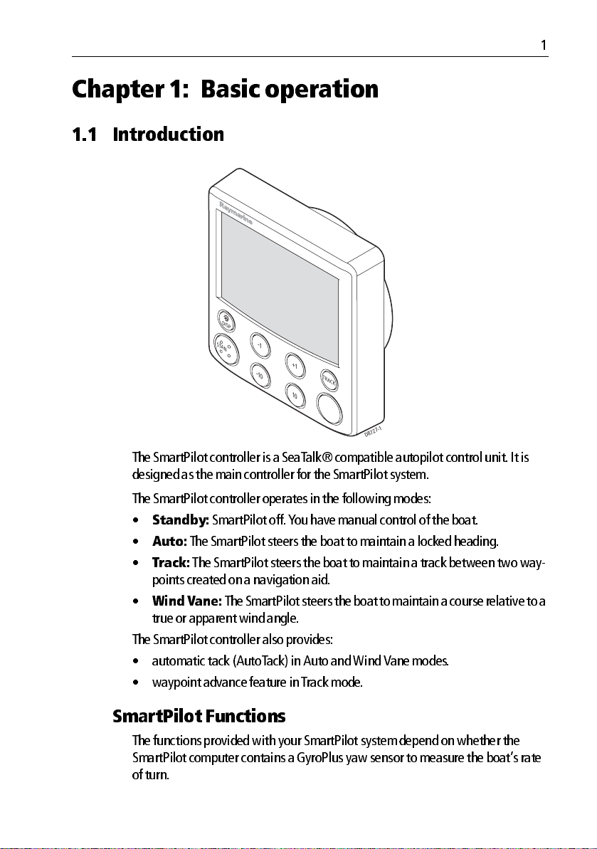
The Smar tPilot controller is a SeaT alk® c ompatible autop ilot control unit . It is
designed as the mai n controller for the SmartP ilot system.
+
1
-
10
TR
A
C
K
10
A
U
T
O
D8727-1
1
The Smar tPilot controller o perates in the following mo des:
•
Standby:
•
Auto:
•
Track:
SmartPilot off . Y ou have manua l control of the boat.
The SmartP ilot steers the boat to mainta in a locked h eading.
The SmartPi lot steers the boat to maintain a track between two way
points created on a navigation aid.
•
Wind V ane:
The SmartPil ot steers the boat to maintain a c ourse relative to a
true or apparent win d angle.
The Smar tPilot controller also provides:
• automatic tac k (AutoT ack) in Auto and Wind Van e modes.
• waypoi nt advance feature in T rack mo de.
SmartP ilot Funct ions
The fun ctions provided with yo ur SmartPilot system d epend on whether the
SmartPilot co mputer contains a Gyro Plus yaw sensor to measure th e boat’s rate
of turn.
Page 12
2 S1 Wheel and Tiller Pilots Operating Guide
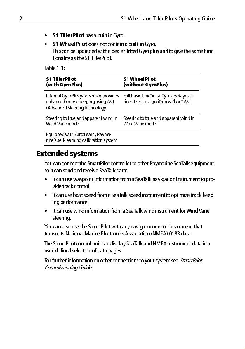
•
S1 TillerPilot
•
S1 WheelPilot
has a built in Gyro .
does not contain a builtin Gyro.
This c an be upgraded with a dealerfitted Gyro plus unit to give the same func
tionality as the S1 TillerPilot .
:
T able 11:
S1 TillerPilot
(with GyroPlus)
Internal GyroPlu s yaw sensor provides
enhanced course keeping us ing AST
(Advanced Steering T echnology)
Steering to true and apparent wind in
Wind Vane mode
Equipped with AutoLearn, Rayma
rine’s selflearnin g calibratio n sys tem
S1 WheelPilot
(without GyroPlus)
Full basic functionality : uses Rayma
rine steering algorithm without AST
Steering to tr ue and apparent win d in
Wind Vane mode
Extended systems
Y ou can connect the SmartPilot con troller to other Raymarine SeaT alk equipment
so it can send and recei ve SeaTalk da ta:
• it can use way point informa tion from a SeaT alk naviga tion instrument to pro
vide track control.
• it can use b oat speed from a SeaT alk speed instr ument to optimize t rackkeep
ing performanc e.
• it can use wind inform ation from a SeaT alk wind instru ment for Wind V ane
steering.
Y ou can also use th e SmartPilot with any navig ator or wind instrumen t that
transmits Nationa l Marine Electronics Assoc iation (NMEA) 0183 data.
The SmartP ilot control un it can display SeaT alk and NMEA instrument data in a
userdefined selection of data pages .
For furth er information on oth er connections to yo ur system see
Commissioni ng Guide.
SmartPilot
Page 13
Chapter 1: Basic operation 3
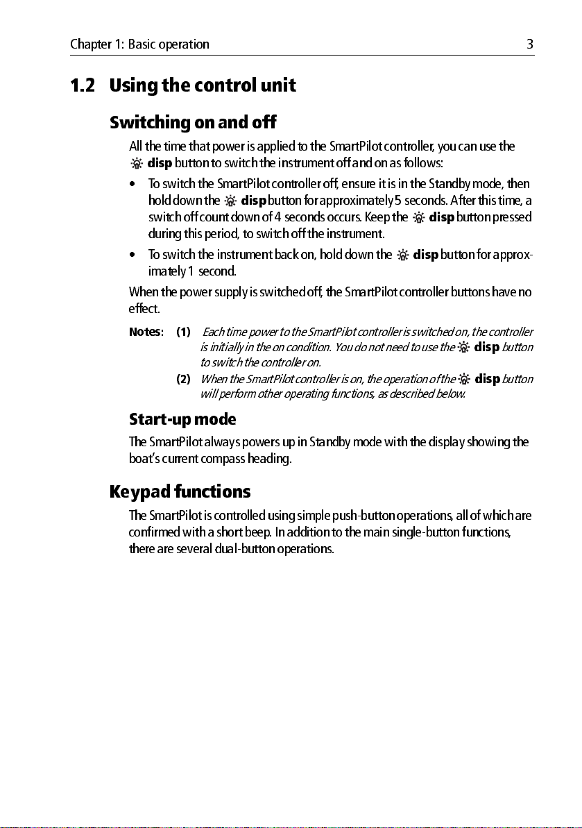
1.2 Using t he control unit
Switchi ng on and o ff
All the time that p ower is applied to the SmartPi lot controller, you can use the
disp
button to switch the instru ment off and on as follows:
• T o switch the SmartPil ot controller off , ensure it is in the Stan dby mode , then
disp
hold down the
switch off count down of 4 seconds occurs . Keep the
during thi s period, to switch off the instru ment.
• To switch the instrument back on, hold down the
imately 1 second.
When the power supply is switched off, the SmartPilot con troller buttons have no
effect.
Notes: (1)
Each time power to the SmartPilot con troller is switched on, the contro ller
is initially in the on con dition. You do no t need to use the
to switch t he contro ller on.
(2)
When the SmartPilo t controller is on, t he operation of the
will perform ot her operat ing fun ctions , as describ ed below .
Startup mode
The Smar tPilot always po wers up in Standby mo de with the display showin g the
boat’ s current compa ss heading.
button for a pproximately 5 seconds. After this time, a
disp
button pressed
disp
button for approx
disp
button
disp
button
Keypad functions
The Smart Pilot is controlled using sim ple pushbutton operat ions, all of which are
confirmed with a sh ort beep. I n addition to the ma in singlebutton functions ,
there are several dualbutto n operations .
Page 14
4 S1 Wheel and Tiller Pilots Operating Guide
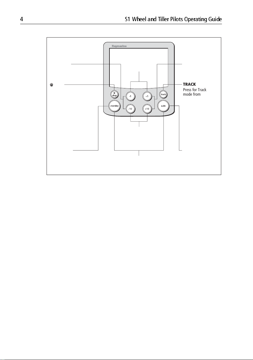
-1 plus +1
-1 plus -10
Press together for
AutoTack to port
Press for Response level
Press for 1 second
for Rudder Gain
+1 plus +10
Press together for
AutoTack to starboard
DISP
Press to display data pages
Press for 1 second for lamp
adjust
Press for 3 seconds for
contrast adjust
Press for 9 seconds
(in Standby mode) for
power down
When powered down, press
for 1 second to power up
STANDBY
Press for Standby mode
Press for 2 seconds to enter
Calibration mode
Course change keys
Port 1˚ Starboard 1˚
Port 10˚ Starboard 10˚
STANDBY plus AUTO
Press for Wind Vane mode
(if a wind vane is connected)
TRACK
Press for Track
mode from Auto
(if a navigator is
connected)
Press to accept
waypoint advance
Press for 1 second
to skip waypoint
AUTO
Press for Auto mode
D5449-3
Page 15
Chapter 1: Basic operation 5
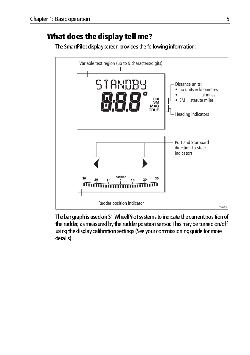
What does the display tell me?
The Smar tPilot display screen provides the following info rmation:
Variable text region (up to 9 characters/digits)
Distance units:
• no units = kilometres
n
S
MAG
TRUE
m
M
• nm = nautical miles
• SM = statute miles
Heading indicators
Port and Starboard
direction-to-steer
indicators
Rudder position indicator
D5457-3
The bar gra ph is used on S1 WheelPilot systems to indicat e the current position of
the rudder, as measured by the rudder posi tion sensor. This may be turn ed on/off
using the disp lay calibration setti ngs (See your commissio ning guide for mor e
details).
Page 16
6 S1 Wheel and Tiller Pilots Operating Guide
1.3 Using the SmartPil ot to steer your boat
CAUTION: Maintain a permanent watch
Automatic course contr ol makes it easier to sail a boat, but it is
NOT a substit ute for good seaman ship. AL WA YS ma intain a
permanen t watch by th e helm.
CAUTION: Risk of gybe
Always be aware of the relative wind angle, especially wh en using
the au topilot to sail down wind.
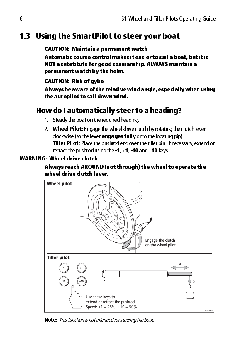
How do I automat ically st eer to a hea ding?
1. Steady the boat on the required heading.
2.
Wheel Pilot:
clockwise (so the lever
Tiller Pilot:
retract the pushrod using the
WARNING: Whee l drive clutch
Always reach AROUND (not th rough) t he wheel to oper ate the
wheel drive c lutch lever.
Wheel pilot
Engage the wheel drive clutch by rotating the clutc h lever
engages fully
onto the locating pip).
Place the pushrod end over the tiller pin. If necessary , extend or
1, +1, 10
and
+10
keys.
Tiller pilot
Use these keys to
extend or retract the pushrod.
Speed: +1 = 25%, +10 = 50%
Note:
This function is not int ended for steering the boat.
Engage the clutch
on the wheel pilot
a
b
D5341-2
Page 17
Chapter 1: Basic operation 7
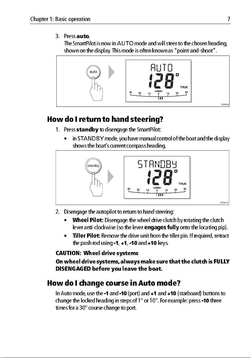
3. Press
auto
.
The Smart Pilot is now in
AUTO
mode and will steer to the ch osen heading,
shown on the disp lay . Th is mode is often known as “po intandshoot ”.
How do I r eturn t o hand stee ring?
1. Press
2. Disengage the au topilot to return to h and steering:
standby
•in
STANDBY
to disengage the SmartPil ot:
mode , you have manua l control of the bo at and the display
shows the boat’ s current comp ass heading.
•
Wheel Pilot:
lever anticlo ckwise (so t he lever
•
Tiller Pilot:
the push rod usi ng
Disengage the wheel drive clutc h by rotating the cl utch
engages fully
Remove the drive unit from the tiller pin . If required, retract
1, +1, 10
and
+10
TRUE
keys.
TRUE
D3560-6
D3561-6
onto the locatin g pip).
CAUTION: Whe el drive systems
On wheel drive systems, always make sur e that th e clutch is FU LL Y
DISENGAGED before you leave t he boat.
How do I change course in Auto mode?
In Auto mo de, use the 1 and
change the locked heading in steps of 1° or 10°. For example: press
times for a 30° course ch ange to port.
10
(port) and +1 and
+10
(starboard) buttons to
10
three
Page 18
8 S1 Wheel and Tiller Pilots Operating Guide
Port Starboard
or
or
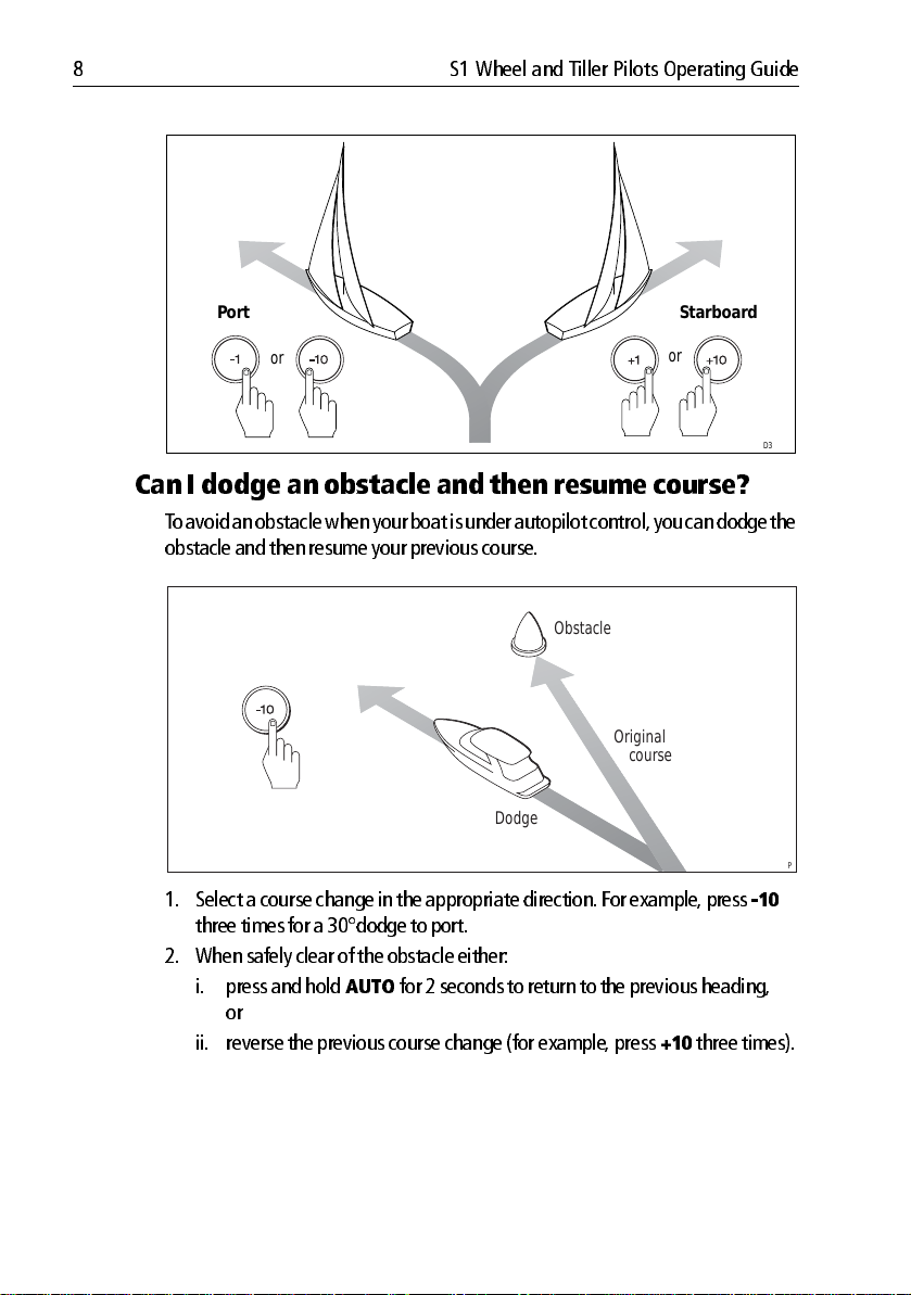
Can I dodge an obstacle and then resume course?
T o avoid an o bstacle when your boat is under au topilot control, you can do dge the
obstacle and th en resume your previous cou rse.
Obstacle
Original
course
Dodge
1. Select a course change in the appropriate direct ion. For examp le, press
three times for a 30°dod ge to port.
2. When safely clear of the ob stacle either:
i. press and hold
or
ii. reverse the previous course change (for example , press
AUTO
for 2 seconds to return to th e previous heading,
+10
three times).
D3303-3P
10
D3320-3
Page 19

Chapter 1: Basic operation 9
Off Cour se alarm
= deviation to port
= deviation to starboard
D3315-5
The SmartP ilot warns you when you have been off course from the locked headi ng
for long er than 20 seconds . It shows whether the deviatio n is to po rt or starboa rd.
The w arning automati cally clears if the heading recovers or if you change cou rse.
1. T o cancel the off course w arning, press
standby
to return to manual steer
ing.
2. Check whether your b oat is carrying too m uch sail, or whether the sails are
badly bala nced. Y ou can usu ally significantly improve course k eeping by
improving th e sail balance.
Note:
The default off course angle is set at 20º. You can adjust this angle in Dealer Cali
bration (see SmartPilo t Commission ing Guide).
1.4 How do I adjus t the perf ormance of my SmartPilot?
The pri ncipal method o f adjusting the performan ce of SmartPilot systems is by
changing the response level. Th is is the only user adjustm ent you should need to
make to y our Sm artPilot on a regula r basis .
The respo nse level controls the relationsh ip between the SmartPilot’ s course
keepin g accuracy and th e amount of helm/d rive activity . When you tu rn on your
SmartPilot it will alway s be at the defau lt level. (Thi s level can be ad justed in User
Calibration
When you req uire extra tight course k eeping (e.g . for pilotage in con fined and
sheltered waters), in crease the setting. If yo u want to minim ize drive activity and
conserve battery po wer , decrease the setting.
Y ou can mak e temporary ad justments to the response level when usi ng your
SmartPilot on a daytoday basi s. By doin g this you can matc h performance to
conditio ns as they occur .
see page 31 )
Page 20

10 S1 Wheel and Tiller Pilots Operating Guide
Note:
You will los e these t emporary changes t o respo nse level whenev er the s ystem is
powered off. You can make permanent ad justments in User Calibrat ion (See page 31). This
determines t he default powerup r espons e level.
Adjusting perform ance
TillerPilot ( and gyro upgr aded WheelPilot )
S1 Tiller Pilot (and gyro up graded WheelPilo t) systems have 9 levels of response:
•
level 9 to 7
give the tightest course k eeping and greatest ru dder activity
(and power con sumption). T his can lead to a rough passage in open waters as
the SmartPilot ma y ‘fight’ the sea.
•
levels 6 to 4
should give good co urse keeping with crisp, well co ntrolled
turns under no rmal operating con ditions .
•
level 3 to 1
minimizes the amou nt of pilot activity. This con serves power , but
may compro mise shortterm coursek eeping accu racy .
With these points in mind, you sho uld use the following p rocedure to mak e
temporary ad justments to the response level when requ ired:
1. Display the
RESPONSE
screen by pressing the
1
and +1 buttons together
momentarily.
Note:
The
RESPONSE
sioning Guide) s o you can also access it by pr essing
data pages.
2. Press 1 or
+1
screen is set as a default data p age (see Smart Pilot Co mmis
disp
and then s crolling throug h the
buttons to change the respon se level.
3. Press
Decrease
response
disp
or wait for 5 seconds to return to the previous displ ay .
Increase
response
D5452-3
Page 21

Chapter 1: Basic operation 11
Adjusting perform ance
S1 WheelP ilot (without gyr o)
S1 WheelPilot sy stems (without a gyro up grade) have three different response
levels:
• Response Level 1: Aut oSeastate on (Automatic deadband)
The SmartPilot will gradually ignore repetitive boat movements and
only react to true variations in course. This provides the best compromise between power consumption and course keeping accuracy.
• Response Level 2: Aut oSeastate off (Minimum deadba nd)
This setting provides tighter course keeping but will lead to increased
power consumption and drive unit activity.
• Response Level 3: Aut oSeastate off + yaw damping
This setting provides the tightest possible course keeping by introducing
counter rudder yaw damping You can adjust the counter rudder setting in
Dealer Calibration (see SmartPilot Commissioning Guide).
To make a
1. Display the
2. Press
3. Press
Note:
powered off. You can make permanent adjust ments in User Calibration (see page 31).
temporary
1
or +1 buttons to chan ge the response between levels 1 to 3.
disp
or wait for 5 second s to return to the previous disp lay .
You will los e these t emporary changes t o respo nse level wh enever the s ystem is
change to the respon se setting:
RESPONSE
screen by pressing the
1
and +1 buttons together.
1.5 Sailing func tions
Ta cking (Aut oTac k)
CAUTION: Allow tim e for course ch anges
When ma king major course changes, the trim on the boat m ay
change su bstantially . Due to this , the Sm artPilot may take some
time to settle accurately onto the new course.
The Smart Pilot has a built in automatic tac k facility (AutoT ack) that turns the boat
in the required di rection for a tacking man euver .
When you A utoT ack the boat turns th rough the AutoT a ck angle (100° default).
Y ou should then trim the helm to mirro r the wind angle from the previou s tack.
• To AutoTack to port
i. Press the 1 and
ii. Use the
angle.
+1
and
10
buttons together. The boat will then AutoT ack.
+10
buttons to trim the helm back to the required win d
Page 22

12 S1 Wheel and Tiller Pilots Operating Guide
• To AutoTack to starboard:
i. Press the +1 and
ii. Use the
1
and
+10
buttons together. The boat will then A utoT ack.
10
buttons to trim th e helm back to the required wind
angle.
AutoTack - Port
Helm
trim
AutoTack
Helm trim
+
Wind Wind
AutoTack
angle
AutoTack - Starboard
Helm trim
AutoTack
angle
+
AutoTack
+
AutoTack angle
Y ou should set the A utoTac k angle to 20° greater than the ac tual required change
of heading.
Example
If you wish to tack through 8 0° (i.e when sailing at 4 0° to the wind) you should set
the AutoT ack ang le to 100°. T he SmartPilot will Aut oT ack through the larg er
angle , you should then use the SmartPilot con trols to trim the helm bac k to the
required 40° relative to th e wind.
Helm
trim
+
D9318-1
Y ou can adju st the default AutoT ack ang le in User Calibration (see
page 30
).
Preventing gybes with AutoTack
The gy be inhibit feature prevents an A utoT ack away from th e wind – this will
prevent the AutoT ack featu re from gybing.
Note:
For the gybe inhibit featur e to work, the SmartPilot needs suitable wind inform a
tion.
Gybe inhibit is switched on as a default but can be disabled in User Calibration if
required
(see page 30)
.
Page 23

Chapter 1: Basic operation 13
With gybe in hibit on:
• you will be able to perform an AutoT ack int o the wind.
• the autopilo t will prevent the boat from performi ng an AutoT ack aw ay from
the wind, to prevent acc idental gybes .
With gybe in hibit off:
• you can perfor m an AutoT ack into o r away from the wind.
Note:
Gybe inhibit is switched on as a default but can be disabled in User Calibration (see
page 30).
Gusty co nditions
CAUTION: Risk of gybe
Always be aware of the relativ e wind angle, especially wh en using
the Aut opilot to sail down wind.
In gusty conditions, the course may tend to wander slightly , partic ularly if the sails
are badly bala nced. If you tak e the following preca utions, the SmartPilot will be
able to maintai n competent contro l even in gale force condition s:
• Y ou can imp rove course keeping by improving the sail balance:
• do not allow the b oat to heel over excessively .
• ease the mainsheet traveller to leewa rd to reduce heeling and weather
helm.
• if necessary , reef the mainsa il a little early .
• In very strong wind s and large seas, you should avoid sailing with the wind
dead astern:
• ideally , br ing the wind at least 30° awa y from a dead run.
• in severe conditions , you m ay also need to remove the mainsa il and sail
under headsail only.
Page 24

14 S1 Wheel and Tiller Pilots Operating Guide
1.6 Displa y lighting & con trast ?
Adjusting the display lighting
Y ou can adju st the display and k eypad ligh ting by:
1. Pressing
turn on the ligh ts.
.
1 second
disp
for 1 second from any mode to access the
LAMP
screen and
D3313-5
2. Press the
LAMP 3
LAMP 2, LAMP 3
disp
button to cy cle through the po ssible illumination settings:
(the brightest setting)
, LAMP 2, LAMP 1, OFF, LAMP 1,
and so on:
• as you chang e the setting, the illumin ation on any oth er SeaTa lk instru
ments or control units will also change.
3. The disp lay automatical ly returns to the previous mo de if you do not press a
button for 10 seconds:
• if you press anoth er mode button within 10 seconds you will selec t the
mode assigned to that button (for example:
standby
Notes: (1)
Notes: (1)
selects Standby mod e).
You can also adjust the lighting level from any other SeaTalk instrum ent
or contro l unit.
When you s witch off th e unit you los e any chan ges you have m ade to
the lightin g level.
auto
selects Auto mode ,
Adjusting the contrast
T o set the display co ntrast level:
disp
1. With the autopi lot in Standby mo de, press the
access the
2. Press the
LAMP
screen.
disp
button for one secon d again, to disp lay the
screen.
3. Use the
+1
and
1
buttons to set the required contrast level (from 1 to 15).
button for on e second to
CONTRAST
Page 25

Chapter 1: Basic operation 15
4. The di splay automatica lly returns to the previous mo de if you do not press a
button for 10 seconds:
Note:
if you p ress an other mo de butt on within 10 seconds you will s elect the mo de as
signed to that bu tton (for example:
mode).
auto
selects Auto mode,
standby
selects Standby
Page 26

16 S1 Wheel and Tiller Pilots Operating Guide
Page 27

Chapter 2: Advanced operation
2.1 How do I foll ow a route s et on a Chart plotter?
CAUTION: Sa fety in T ra ck mode
T rack mode pr ovides accur ate tra ck keeping even in complex
navigationa l situations . However, it is still th e skipper’ s
responsibility to ensur e the safet y of their boat at all time s
thr ough caref ul navigation and freque nt position check s. T rack
mode assists pre cise navigation and removes the tasks of
compensating f or wind and tidal drif t. However, you MUS T still
maintain an accur ate log with r egular plots .
In T rack mo de, the Sm artPilot mainta ins a route between w aypoints created on a
navigation sy stem. It makes an y course changes necessary to keep you r boat on
course , automaticall y compensating for tidal streams and leeway.
T rack mode is avail able only if you have con nected the SmartPilot to a suitable
navigation sy stem providing SeaT alk or NMEA in formation.
Commission ing Guide for connecti on details)
Y our SmartPil ot system can receive route inform ation from:
• a SeaT alk navigation in strument or chartplo tter .
• a navigation syst em transmitting data in NMEA 0183 format.
(See SmartPilot
17
How do I a ctivate T r ack mode?
CAUTION: Ma ke suitable pr eparation s for enterin g track mode
When you enter T ra ck mode, th e SmartP ilot will bring the boat
onto the track in a controlled way . The closer the boat is to the cor
rect heading and t rack, t he quicker it will settle the boat onto t he
new course . To av oid an unexpect ed turn, align the boat a pproxi
mately with the required track before entering Track mode.
Starting with the Smart Pilot in A UTO mode an d your chartplo tter following a
route.
1. Press
2. Wai t for the warning to sou nd.
track
to enter T rack mode .
The disp lay will show the bearing to the next planned waypo int and the direc
tion in which th e boat will turn to reach thi s waypoint.
Page 28

18 S1 Wheel and Tiller Pilots Operating Guide
3. If it is safe for the boat to turn on to the new course , press the
• the SmartPilot will tu rn the boat onto the new cou rse.
• the display will sh ow the heading required to achieve the required track.
Note:
If the boat is more than 0.3 nm from the track, th e Large Cross Track Error warnin g
will sound (see page 18 ).
Waypoint arrival Waypoint advance
Next target
Waypoint at 270˚
Target
Waypoint
TRUE
Old target
Waypoint
How do I leave T ra ck mode?
Y ou can leave T rack mode at an y time by:
• pressing
• pressing
auto
to return to Auto mode.
standby
to steer manually in Standby mode .
track
button:
New target
waypoint at 270˚
TRUE
D5416-4
Cross track error?
Cross track error (XTE) is the di stance between the current positio n and a planned
route . The SmartPi lot receives the cross track error informati on from the
navigation equi pment, and displays the XTE in nautical miles (nm), statute miles
(SM) or kilometres (km).
Cross tr ack err or course corr ection
The auto pilot will automati cally steer to correct the cou rse whenever it detects a
cross track error .
Page 29

Chapter 2: Advanced operation 19
CAUTION: Th e direction of turn an d the displayed bearin g to
waypoint may be different from that expected.
Example:
Course correction
Example1:
Initial turn toward waypoint
Target
Waypoint
Example2:
Initial turn away from actual
waypoint position.
Target
Waypoint
Cross
track error
Cross
track error
TRUE TRUE
D9416-1
Page 30

20 S1 Wheel and Tiller Pilots Operating Guide
Large cr oss trac k error
If the cross track error is greater tha n 0.3 nm, the Smart Pilot will sound the L arge
Cross T rack Er ror warning and show whether you are to the p ort (Pt) or starboard
(
Stb
) of the planned track.
Cross track error (XTE)
more than 0.3 nm
Actual route
Planned route
Waypoint 1
Waypoint 2
Tidal stream compensa tion
Under most con ditions, t he SmartPilot will hold the selected track to within ± 0.05
nm (300 ft) or better . It takes acco unt of the boat’s speed when compu ting course
changes to ensure o ptimum performan ce.
Waypoint 2
Boat's speed over ground
Tidal component
D5415-4
Waypoint 1
Boat's speed through water
D3261-4
Page 31

Chapter 2: Advanced operation 21
How do I d odge an obs tacle in T r ack mode ?
In T rack mode yo u still have full control from the keypad. Y ou can mak e a dodge
maneuver by usin g the course change bu ttons (
1,+1
,
10
or
+10
) to select the
desired course cha nge.
On making a dod ge maneuver , the auto pilot will revert to A UTO mode . Once you
are safely past the obstac le, re initiate T rac k mode to continue on your planned
route.
What hap pens when I arrive at a waypoint ?
As the boat arrives at the targ et waypoint the ch artplotter will select the next
target wayp oint and transmit th is to the SmartPilot. It will then detect the new
target wayp oint name , sound a W aypoint Ad vance warning and display the
Way point Advan ce (NEXT WPT) screen. This sh ows the new bearing to the next
waypoi nt and the direction th e boat will turn to acqui re the new track.
Waypoint arrival and advance
Next target
Waypoint at 270˚
New target
waypoint at 270˚
Target
Waypoint
TRUE
Waypoint arrival Waypoint advance
Old target
Waypoint
How do I get to the next waypoint in a route?
When the W aypoint Ad vance warning sounds , the SmartPilot suspen ds T rack
mode and mai ntains the current boat heading.T o adv ance to the next waypoin t:
1. Check that it is safe to turn on to the new track.
2. Press the
turn the boat tow ards the next waypo int.
Note:
maintain the current headi ng and continue sound ing the warning.
track
button. T his will cancel the W aypoint Advance warni ng and
If you do not press
track
to accept the Waypoint Advance, the SmartPilot will
TRUE
D5416-4
Page 32

22 S1 Wheel and Tiller Pilots Operating Guide
How do I skip a waypoint? (SeaTalk chartplotters)
If you want to advance to the next wayp oint
target waypo int, you can skip a waypoint by pressing
display will then show the W aypoint Advance screen for the next waypoin t. Check
it is sa fe to tu rn, t hen press
WARNING: Ensure nav igation safety
Skipping a waypoint will take you str aight to t he next way point.
Check your navigation befor e making th e turn.
Always be aware of the r elative wind an gle, especially when
turnin g away from t he wind.
track
to turn the boat towar ds the next waypoint.
before
you have arrived at the
track
for 1 se con d. T he
What is the Waypoint Advance alarm?
The SmartP ilot activates the W aypoint A dvance alarm (NEXT WPT?) in T rack
mode whenever the target wa ypoint name chan ges. T his occurs when:
• you select autom atic acquisition b y pressing
• you request w aypoint adv ance by pressing
(with SeaT alk navigators onl y)
• the boat arrives at the target and the navigator accepts the next wa ypoint
• you activat e the Man Overboard (MOB) function (see
When the alarm sou nds, th e SmartPilot continu es on its current heading but
displays:
• the bearing to the next w aypoint
• the direction the b oat will turn to tak e up that bearing
track
from Auto
track
for 1 second in T rack mode
page 28
)
How do I respond t o a Waypoint Advance alarm?
T o respond to a W aypoin t Advance alarm:
• check that it is safe to turn onto the new
waypoin t advance
• alternatively , yo u can cancel the alarm with out accepting the w aypoint
advance by pressing:
•
auto
to continue on the same heading, or
•
standby
to return to manual control
track
, then press track to accept the
What happens when I get to the end of the route?
The SmartP ilot displays the
reached the last way point on a route in Tra ck mode.
• press
auto
to continue on the same head ing.
ROUTE COMPLETED
warning when yo u have
Page 33

Chapter 2: Advanced operation 23
• or press
Note:
DATA when you reach the final waypoint.
standby
If waypoints are provid ed using an NMEA connection the controller will display NO
to return to manual co ntrol.
2.2 Using Wind V ane mode
Note:
You can only select Wind Vane mo de if the SmartPilot is receiving suitable SeaTalk
or NMEA wind direction infor mation.
What is Wind V ane mode?
When the SmartPil ot is in Wind V ane mode it uses the fluxgate comp ass as the
primary heading reference. As changes in the true or apparent wind angle occur,
it adjusts the lock ed heading to maintain the origi nal wind angle .
Wind i nform ation
T o use Wind V ane mode , the SmartPilot mu st receive wind information from one
of the following sources:
• SeaT alk wind instrumen t connected to the auto pilot via SeaT alk
• NMEA wind instrum ent
• Raymarine push pit wind vane conn ected via a SeaT alk interface
T rue and apparent wind
SmartPilots can maintain a course relative to eith er an apparent or true wind
angle in Wind Vane mode
The default setting is apparent wind. If req uired, you can chang e this to true wind
in User Calibration (see
page 31
).
WindTrim
In Wind V ane mode the SmartP ilot uses WindT rim to eli minate the effects of
turbulence an d short term wind variati ons. T his provides smoo th and precise
performance with m inimal power consum ption. Y ou can adjust the wind
response (WindT rim) level in User Calibration (see
the SmartPilot resp onds to changes in th e wind direction. H igher wind trim
settings will result in a p ilot that is more responsive to win d changes .
page 31
) to contro l how quickly
Page 34

24 S1 Wheel and Tiller Pilots Operating Guide
How do I select Wi nd V ane mode ?
Y ou can select Win d Vane mod e from either Standby or Au to mode:
1. Steady the boat on to the required wind ang le.
2. Press
3. In Wind V ane mode , the SmartPilot will th en adjust the boat’ s heading to
standby
and
auto
together to select Wind V ane mode and lock the
current wind angle:
• the display shows the locked heading (e.g. 128°) and the wind angle
(e.g.
WIND 145P
indicates an wind an gle of 145° to port)
• if the SmartPilot do es not enter Wind V ane mode, it is not receiving wind
data check the instrum ent and connectio ns
+
MAG
D3565-6
maintain the lo cked wind ang le.
How do I leave Wind Vane mode?
Y ou can leave Wind V ane mode by :
• pressing
• pressing
auto
to return to Auto mode.
standby
to return to manu al control.
How do I adjust the locked wind angle
Y ou can adjust the locked wind angl e by using the 1, +1,
change course . For example , to bear away by 10° when the boat is on a starboard
tack:
10
• press
to turn the boat 10 ° to port – the lock ed wind angle and locked
heading will bo th change by 10 °.
• the autopilot will then adjust the lock ed heading as requ ired to maintain the
new wind angle.
Note:
Because turning the boat affects the relation ship between the true and apparent
wind angles, you should only u se this method to m ake minor adjustm ents to the wind an
gle. For major changes, return to Stan dby mode, s teer onto the n ew heading, then r eselect
Wind Vane mo de.
10
and
+10
buttons to
Page 35

Chapter 2: Advanced operation 25
How do I dodge an obstacle in Wind V ane mode?
In Wind V ane mode you still have full control from the k eypad. Y o u can make a
dodge maneuver by using the course change buttons (
select the desired cours e change.
After you have avoided the hazard, you can cancel the dodge cou rse change by
making an equ al course change in the op posite direction.
1,+1
,
10
or
+10
) to
What is a Wind Shift warning?
If the autopilo t detects a wind shift of more than 15 ° it will sound the wind shift
warning and display the
• T o cancel the warn ing, and retain th e existing wind angle and new head ing,
standby
press
• Alternatively , to cancel the warning and return to the previous h eading:
• adjust the lock ed wind angle u sing the
• press
standby
ing, an d press
with the new wind angle .
WIND SHIF T
and
auto
together.
to return to hand steering, steer onto the requ ired head
standby
and
message:
1, +1, 10
auto
together to retu rn to Wind Vane m ode
and
+10
buttons.
How do I use AutoTack in Wind Vane mode?
Note:
If you use t he AutoTack function in Wind Vane mode, m ake sure the wind van e has
been centered accurat ely.
The Smart Pilot has a built in automatic tac k facility (AutoT ack) that turns the boat
in the required di rection for a tacking man euver .
When you A utoT ack in Wind V ane mode , the boat turns th rough the AutoT a ck
angle (100° defau lt). The SmartPi lot will then trim the helm to m irror the lock ed
wind angle from th e previous tack.
• T o AutoT ack to p ort: press the 1 and
• T o AutoT ack to star board: press the +1 and
10
buttons together.
+10
buttons tog ether .
Page 36

26 S1 Wheel and Tiller Pilots Operating Guide
AutoTack - Port
Automatic
Helm
trim
Wind Wind
AutoTack - Starboard
Automatic
Helm
trim
AutoTack
+
AutoTack
angle
AutoTack
angle
AutoTack
+
AutoTack angle
When sailing in Wind Van e mode you should set the AutoT ack angle to 20 °
greater than the actua l required change of head ing.
Example
If you wish to tack through 8 0° (i.e when sailing at 4 0° to the wind) you should set
the AutoT ack ang le to 100°. T he SmartPilot will Aut oT ack through the larg er
angle and then tri m the helm back to the wind v ane locked head ing.
Y ou can adju st the default AutoT ack ang le in User Calibration (see
page 30
Oper ating hi nts for Wi nd V ane mode
• Always trim your sails carefully to minimize the amoun t of standing helm.
• Reef the headsail and main sail a little early rather than too late.
• In Wind V ane mode the SmartPilot will react to long term wind shifts, but will
not correct for shor tterm changes such as gu sts.
• In gusty and unsteady inshore co nditions , it is best to sail a few degrees fur
ther off the wind so that chan ges in wind direction can be tolerated.
D9320-1
).
Page 37

Chapter 2: Advanced operation 27
2.3 How do I displ ay boat data?
Use the
disp
button to show ‘da ta pages’ of SeaT alk or NMEA data:
1. Press
Notes: (1)
Default data pages
disp
to access the first data page , and press it aga in to cycle throug h
each data page in turn:
• when you cyc le past the last data page , the display retu rns to the current
SmartPilot mo de screen (for example, AUT O).
• 4 data pag es are set in the factory as a default (see diagram): within User
setup you can select up to 15 pages and control the informatio n they dis
play (see
SmartPilot Co mmission ing Gu ide
If the SmartPilot system canno t obtain the required informa tion, the data
page will show dashes instead of a value.
(2)
The directionto steer arrows relate to the data page informat ion.
(3)
Most data pages sho w repeated data so you cannot adjust th em: the
exceptions are the
which you can adjust using th e
RESPONSE
).
and
RUDDER GAIN
1
and
+1
data pages ,
buttons
Data page 4
Data page 3
Autopilot mode
Press for 1 sec to
return to previous
data page
Data page 1
Data page 2
Can I dis play Wa ypoint na mes?
If waypoi nts have been given names , the SmartPilot con troller will display th em
on the Cross T rack Error (
Waypoint (
DTW
• waypoi nt names of five characters or less are display ed together with the
page name (as shown b y screen A below).
• waypoi nt names of more than five characters alt ernate with the page name
(as shown by screenB below).
XTE
) data pages:
), Bearing T o W aypoint (
BTW
) and Distance T o
D5455-3
Page 38

28 S1 Wheel and Tiller Pilots Operating Guide
• if the waypoin t name has more than nin e characters, the display only sh ows
the first n ine ch aracters .
TRUE TRUE
A
TRUE
2.4 Alarms
The SmartP ilot may activate th e alarms listed on the followin g pages. When
displayin g an alarm the sounder will beeping and the disp lay will show the
appropriat e alarm message.
Responding to alarm s
• Unless otherwise st ated, you shou ld deal with al arms by pressing
clear the alarm and retu rn to hand steering.
• In some situatio ns, the auto pilot will raise more than one alarm. When you
have dealt with the first alarm, th e autopilot will disp lay the next alarm.
Message Description and possible actions
LARGE XTE
MOB
B
D8561-1
standby
Large cr oss track err or
Activated when t he cross track erro r exceeds 0 .3 nm . T he alarm
clears if the heading recovers.
Man OverBoard alarm
The SmartPilot activ ates the Man Overboard alarm if it receives a
man overboard (MOB) mess age from another instru ment on the
SeaTalk s ystem. I t dis plays t he text M OB inst ead of t he waypoi nt
number for the XTE, DTW an d BTW data pages .
If the autopilot is in T rack mode, it will soun d the Waypoint
Advance alarm to notify you of the change in waypo int.
to
Page 39

Chapter 2: Advanced operation 29
Message Description and possible actions
NEXT WPT?
OFFCOURSE
(PT or Stb)
Waypoint a dvance ala rm
The SmartPi lot activ ates th e Wayp oint Adv ance alarm whenever
the target waypoint num ber changes. T his occurs when:
• you select automatic acquisition by pressing
• you request waypoint adv ance by pressing
in Track mod e (with SeaTalk navigators only)
• the boat arrives at the target waypoint and the navigato r
accepts the next waypoint
• you activate the Man Overboard (MOB) function in T rack
mode
When the alarm sounds , the pilot contin ues on its current heading
but disp lays:
• the bearing to the n ext wayp oint
• the direction the boat will turn to tak e up that bearing
Responding to a W aypoint Adv ance alar m
To respon d to a Wayp oint Ad vance alar m:
• check that it is safe to turn onto the new track, then press
track
to accept the w aypoint advan ce
• alternatively, you can cancel the alar m without accepting the
waypoint adv ance by press ing:
steering, or
Note: Way point ad vance o nly oper ates if th e Smartpilo t is receiv
ing valid bearing to way point and waypoint number information.
Off course alarm
When the vessel has been off cours e from the lock ed heading for
longer than 20 s econds .
• PT = Deviation to port
• Stb = Deviation to starboard
You can adjust this s pecified alarm angle in Dealer setup, see your
Commission ing gu ide for details.
If this h appens fr equently yo u sho uld check s ail balance and also
review autopilot performance . See
auto
to return to Auto mode .
standby
page 9
track
track
to return to hand
.
from Auto
for 1 second
SHALLOW
WINDSHIFT
Shallow ala rm
The SmartPilot activ ates the Shallow alarm if it receives a shallow
depth alarm via SeaT alk:
•press
Large wi nd shift warning
Indicates a chan ge in t he apparent wind an gle of mo re than 15º.
See
page 25
standby
.
or
disp
to cancel the alarm
Page 40

30 S1 Wheel and Tiller Pilots Operating Guide
2.5 User Calibrat ion Options
The cali bration informatio n in this handbo ok relates to only those setting s that
can be adjusted d uring normal op eration (
available cali bration settings , see
Note:
Many of the settings are sailb oat specific and will only be displayed if your vessel
type is set to
SAILBOAT
.
SmartPilot Com missioning Guid e.
How do I access Us er Calibr ation s ettings?
Y ou can only access the calibration m ode from Standby mo de:
1. With the SmartP ilot in Standby m ode, press an d hold the
2 seconds . The di splay will change to sh ow
2. Press the
3. Press
The first pag e of User Calibration will now be disp layed.
4. T o access other User Calibratio n pages, press
items within that gro uping:
5. When you reach an item y ou wish to ad just, use the
tons to change the val ue.
6. When you have mad e all the changes you w ant to make , press and ho ld
standby
disp
button once , the display will now show
auto
to enter User Calibration.
for two seconds to exit calibra tion mode and save chang es.
USER CAL
DISPLAY CAL
disp
). For infor mation on all
standby
USER CAL
to scroll down th rough the
1, +1, 10
.
button for
.
and
+10
but
User Calibration pages
AutoTack angle
The Au toTack ang le is the angle through which the boat will turn when y ou select
an automatic tack.
Screen T ext Options
AUT O TACK 40° to 125° in 1° steps
Gybe inhibit
With gybe in hibit on:
• you will be able to p erform an AutoT ack into the wind
• to prevent accidental gybes, the SmartPilot will prevent the boa t from per
forming an Au toT ack away from the win d
Page 41

Chapter 2: Advanced operation 31
With gybe in hibit off , you can perform an AutoT ack into or aw ay from the wind.
Screen T ext Options
GYBE STO P ON (Default) = Gybe in hibit o n (gybes prevented)
OFF = Gybe inhibit off (gybes permitted)
Wind selection
This sc reen determines whether the boat steers to ap parent or true wind in Win d
Van e mode.
Options
WIND APP (Default) SmartPilot steers t o apparen t wind an gle
WIND TRUE Smar tPilot steers to true wind angle
WindTrim
WindT rim co ntrols how quickly the SmartPilot respond s to changes in the wind
direction. Higher win d trim setting s will result in a system th at is more r esponsive
to wind changes.
Screen T ext Options
WIND TRIM Range = 1 to 9
1 to 3
Least responsiv e to wind changes (less system
activity)
4 to 6
Moderate response to wind chang es
7 to 9
Most respons ive to wind changes (more system
activity)
Response level
This sets t he default SmartPilot respon se level setting. The respon se level controls
the relationship between course keep ing accuracy and the amount of helm/ drive
activity . You can make temporary changes to response during normal operation,
as described in
Chapter 1, SmartPilot Operatio n
.
Page 42

32 S1 Wheel and Tiller Pilots Operating Guide
S1 TillerPilot (and gyro upgraded WheelPilot) systems
Screen T ext Options
RESPONSE
Range = 1 t o 9
levels 9 to 7
est rudder activit y (and power consumption). T his can lead
to a rou gh pas sage in open w aters as the Smar tPilot may
‘fight’ t he sea.
levels 6 to 4
well controlled t urns under n ormal o perating conditions .
levels 3 to 1
conserves p ower , but may comp romise s hortt erm cours e
keeping accur acy .
Variation
Screen T ext Options
VARIA TION
Apply heading co rrection to allow for v ariance of magnetic
north.
Degrees North, South , East & West.
(Not normally us ed)
gives the tig htest course keeping and great
should give good course keepin g with crisp ,
minimizes the amount of pilot activity . This
Page 43

Chapter 3: Fault Finding & Maintenance
All Raymarin e products are designed to provide many years of trou blefree
operation. We also put them thro ugh comprehen sive testing and quality
assurance p rocedures before sh ipping .
This chapter provides information ab out identifyin g problems , interpreti ng alarm
messages , maintaining your SmartPilot an d obtaining pro duct support.
If a fault o ccurs with yo ur SmartPilot, use the fault find ing tables in this section to
help id entify th e prob lem and provid e a so lution. If y ou c annot resolve the
problem yo urself, refer to the product supp ort information.
3.1 Fault fi nding
SYMPTOM POSSIBLE CA USE and S OLUTION
33
Display is blank
Data page display shows
stationary da shes
Display shows rotati ng dashes
Displayed compa ss heading
does not agr ee with the b oat’s
compass
No display ba r on the display
Rudder bar d isplay moves in
opposite dir ection to rudder
Boat turns slowly a nd takes a
long time to come onto course
Boat ove rshoots when turning
onto a new course
The SmartPilot ‘ hunts’ when
trying to positio n the rudder
No power – check the power and SeaTalk fuses on
course comput er , then check mai n fuse/ circuit
breaker.
The contro l unit is no t receiving necessary d ata from
other instrument s – check cabling.
Compass calibratio n in progress (see SmartPilo t
Commission ing Guide).
Y ou have not calibrated the compass . Carry out th e
deviation and alignment pr ocedures (see SmartPilot
Commission ing Guide).
Rudder bar s witched off i n Display Calibratio n –
select
RUDD BAR
Reverse the red an d green rudder p osition senso r
connections at the course comput er .
Rudder gain too low. Co mplete AutoLearn or increase
gain setting.
Rudder gain too high. Com plete AutoLearn or
decrease gain setti ng.
Adjust the
Commission ing Guide). Increase the damping one
level at a time until the autopilot stops hunting, and
always use t he lowest a cceptable valu e.
RUDD DAMP
or
STEER BAR
setting (see SmartPilot
.
Page 44

34 S1 Wheel and Tiller Pilots Operating Guide
SYMPTOM POSSIBL E CAUSE a nd SOLUTION
The SmartPilot a ppears to be
unstable on Northerly
headings in the Northe rn
hemisphere (or S outherly
headings in the S outhern
hemisphere)
You cannot enter Seatrial
Calibration
The SmartPilot w ill not ‘talk ’
to other SeaTalk instruments
Position informatio n not
received
The SmartPilot w ill not auto
advance to the next waypo int
NonRaymarine 24 V
autopilots clutch slipp ing
When holding a constant
course in ST ANDBY mode, the
heading continuously changes
Jog (+ and keys used to
extend / r etract til ler drive)
doesn’t work i n standby
mode.
Northerly/ Southerly heading correction (AutoAdapt)
is not set up (see SmartPilot Commissionin g Guide).
[Does not apply t o S1G , S2 G and S3G sy stems .]
Seatrial calibration lock is on – turn off the calibration
protection feature in Dealer Calibratio n (see
lot Commiss ioning Guide
Cabling problem – make sure all the cables are con
nected properly.
Navigator not transmi tting t he correct p osition data.
No bearing to wayp oint information received from
the naviga tor.
Check that t he clutch fu se is in the co rrect pos ition.
E.g. 24 V p osition for 2 4 V clut ches .
The Autopilo t is connected to a Raymarine Pathfind er
unit with the “Bridge NMEA Heading ” option
switched on. Disable this featu re on t he P athfin der
unit.
Vess el type is set i ncorrectly . Check vess el type is set
to SAILBOAT .
Refer to the separate commissio ning guide for
details.
).
SmartPi
SmartPilot alarm messages
When the SmartPilo t detects a fault or failure on the system, it will activ ate one of
the alarm messages listed in the following table .
• Unless otherwise stated, yo u should respond to the alarm by pressing
standby
to resolve the problem.
• In some situatio ns, the SmartP ilot will raise more than on e alarm. When you
have dealt with the first alarm, it will display the next alarm.
to clear the alarm and return to manual con trol, before you attempt
Page 45

Chapter 3: Fault Finding & Maintenance 35
ALARM MESS AGE POSSIBLE C AUSE and S OLUTION
CURRENT LIMIT
DRIVE STOPPED
LOW BA TTERY
LRN FAIL 1, 2
or
MOT POW
SWAPPED
NO DA T A
Serious drive failure – the driv e is t aking too much cu rrent du e to
shortcircuit or jamming. Check the drive unit.
The autopil ot is unable to tu rn the rudder (this occurs if the weather
load on helm is to o high, or if the rud der position senso r has passed
beyond the preset rudder limit s or rudder endsto ps).
Check drive and rudder positio n sensor .
Supply voltage has dropp ed below acceptable limits.
To respond to a Low Battery alarm:
• press standb y to clear the alarm and return t o hand steering
• start the engine to recharge the battery
AutoLearn not completed success fully .
4
Failur e codes:
1
= AutoLearn has n ot been car ried out (default s etting)
2
= AutoLearn failed, usually due to manual interr uption
4
= AutoLearn failed, probably due to driv e or compass failure
Repeat the AutoLearn procedur e.
Motor cables ar e connected to power term inals (and po wer cables
are connected to motor terminals) at cour se computer . T urn off
power and swap over connections .
Caused by any of t he following situat ions:
• the compass is not conn ected
• the autopilot is in Wind V ane mode and it has not received wind
angle data fo r 30 seconds
• the autopilot is in T rack mode and:
• the autopilot is no t receiving SeaTalk navigat ion data, or
• the position sen sor (GPS , Loran, Decca) is receiving a low
strength signal – t his will clear when the s ignal im proves
Check connections to the compass , wind instru ment and naviga
tor.
Note:
The auto pilot stop s adjusting the heading as soon as it loses
data.
NO PILOT
NO RUDREF
The contro ller is not receivin g data from th e SmartPilo t compu ter .
Check connections and check cours e comput er is s witched on.
Poss ible fault with rudder positio n sensor – check connections .
Page 46

36 S1 Wheel and Tiller Pilots Operating Guide
ALARM MESS AGE POSSIBLE CA USE and S OLUTION
RG FAIL
SEATALK
FAIL 1
or
SEATALK
and
2
and
GyroPlus yaw sensor has failed:
• If you have a S1G, S2G or S3G cour se computer with internal
GyroPlus sensor – call a Raymarin e service agen t.
• If you have a NonG
yaw sensor – check the sensor and connection s, then call a Ray
marine service ag ent.
SeaTalk dat a prob lem on o ne of t he SeaT alk lines – check con nec
tions.
The control un it cannot transm it data to the SeaT alk system. Mak e
FAIL
sure all SeaTalk cables are connected properl y.
3.2 Gener al maintenanc e
Routine checks
CAUTION: Do not dismantle Sma rtPilot pr oducts
The Smart Pilot computer and contr oller should be serv iced only
by author ized Raymarine se rvice techn icians. Th ese products do
not contai n any user serviceable part s.
The SmartP ilot computer do es NOT contain userserviceable parts . If you remove
the main cover y ou wil l inv alidate th e warra nty. The c ontroller is also a seal ed
unit, so user mai ntenance is limited to the fol lowing checks
• make sure all cable connectors are firmly attached
• examine for signs of wear or dama ge – replace any dama ged cables
Note:
Do not use chemical or abrasive materials to clean the SmartPilot computer. If the
case is dirty, wipe it with a clean, damp cloth.
s
course computer with extern al GyroPlus
Cleaning the display
CAU TI ON: Av oi d da mag e wh en cl ean in g
Take care when cleaning th e display . Avoid wiping t he display
screen with a dry clot h as this could scr atch t he scree n coating. If
necessary , use only a m ild detergent .
• Never use chemical or abrasive materia ls to clean the controller. If it is dirty ,
wipe it with a clean, dam p cloth.
• In certain c onditions, condensation may appear inside the d isplay screen. T his
will not ha rm the unit, and you can clear it b y switching on t he illumination for
a short time .
Page 47

Chapter 3: Fault Finding & Maintenance 37
Wheel dr ive
Routine maintenance
After each trip , flush inside the d rive unit by inserting a ho se pipe in the free slot
on the back cover.
Cleaning the wheel drive
CAUTION:
Do not use mi neralbase d solvents (such as WD40) to lubricat e or
clean th e wheel drive as they will damage the mater ial.
We recom mend that you co mplete the following step s each season to prevent th e
buildup of salt on the wheel drive bearings and drive belt:
1. Remove the wheel drive from the wheel:
• remove the wheel from the pedestal
• remove the spok e clamp screws
• remove the wheel drive front cover
2. Check inside the drive uni t for any signs of damage .
3. Tho roughly flush the wheel d rive interior with fresh water to remove any salt
buildup on the bearings and drive belt.
Do not lubricate any part of the wh eel drive. It is designed t o run
without lub rication.
4. Replace the front cover then fit wheel dr ive back onto the wheel.
5. Fit the wheel and wheel drive back onto the pedestal.
6. Clean the wheel drive case (using m ild detergent if necessary), then flush
thorough ly with fresh w ater.
Adjusting the clutch
Y ou need to adjust the clutch if the drive belt slips in Auto mode or drags in
Standby mo de. In n ormal use, you can tell if the clutch is slipping if the motor
operates but the dri ve does not turn the wheel.
T o adjust th e clutch, first m ake sure th at the autopilo t is in Standby mode and th e
clutch is diseng aged. Th en:
1. Use a 3 mm allen k ey (supplied) to l oosen the clutch knob screw about 2 turns
anticlockwise.
2. T urn the clut ch knob either 4 clicks clockwise t o tighten the clu tch, or 4 clicks
anticlockwise to lo osen the clutch.
3. Use the allen key to retighten the clutch kno b screw .
Page 48

38 S1 Wheel and Tiller Pilots Operating Guide
4. Check that the wheel still moves freely with the clutch off .
Note:
If the wheel d oes not move fr eely, reduce th e clutch t ension b y turn ing th e clutch
knob 2 clicks anticlockwise and check again
5. Check the drive’ s operation with the clu tch engaged.
This p rocedure is usually suffic ient to correct a slipping or dragging dr ive belt. In
some cases , however , you ma y need to repeat the steps to adju st the clutch
further.
Adjusting the clutch
Clutch knob
screw
Clutch knob
Loosen the screw
(2 turns)
1
To loosen
the clutch
(4 clicks)
To tighten
the clutch
(4 clicks)
2
Tighten the screw
(2 turns)
3
D5349-2
Replacing the belt
The drive belt is desi gned to be user serviceable. If there is insu fficient adjustment
to cure a slippin g clutch, or if the drive belt is da maged in any way (if it is broken,
frayed or stretched), you should replac e the drive belt. Y ou can obt ain a
replacement belt from any Raymarine dealer (part number A1808 3). Fitting
instruction s are su pplied with th e belt.
User serviceable parts
Y ou can obta in the following 400 0 mk2 wheel drive spare parts from yo ur
Raymarine dealer:
Page 49

Chapter 3: Fault Finding & Maintenance 39
Part de scription Part number
Fr ont cov er A18074
Clutch lever A18077
Clutch knob A18078
Pedest al brack et (torq ue restr aint) A18080
Drive belt A18083
Clutch kit (clutch eccentric and clutch roller) A18084
Single spok e clamp, screws and inserts A18089
EMC advi ce
• When powered up , all electrica l equipment prod uces electromagnetic field s.
These can cause adjacent pieces of electrical equipment to interact with one
another , with a consequent adverse effect on op eration.
• T o minimize th ese effects and enable you to get the best po ssible perfor
mance from you r Raymarine equipmen t, guidelines are given in the installa
tion instruct ions, to enable you to ensure min imum interaction between
different items of equipm ent, i.e. ensure optimum Electr omagnetic Compa ti
bility (EMC).
• Always rep ort any EMCrelated prob lems to your nearest Raymar ine dealer .
We use such in formation to impro ve our quality standard s.
• In some installa tions, it may not be possible to prevent the equipment from
being affected by external influences. In general this will not da mage the
equipment but it can lead to spurious resetting action, or momentarily may
result in faulty op eration.
Prod uct suppor t
Raymarine pro vides a comprehensive customer su pport service, on the world
wide web and b y telephone help line . Please use either of these fac ilities if you are
unable to rectify a problem.
World wide web
Please visit the Customer Sup port area of our web site at:
www.raymarine.com
As well as providing a comprehensive F requently Ask ed Questions section an d
servicing informati on, the web site gives email access to the Raymarine T echnical
Page 50

40 S1 Wheel and Tiller Pilots Operating Guide
Support Dep artment and a details of the loc ations of Raymarine agen ts,
worldwide.
Telephone help line
If you do no t have access to the world wide web , please call our help lin e.
In the USA
• +1 800 53 9 5539, extensio n 2444 or
• +1 603 88 1 5200 extension 2 444
In the UK, Europe the Middle East or the Far East
• +44 (0) 23 92 71 4713 (voice)
• +44 (0) 23 92 66 1228 (fax)
, call:
, call:
Help us to help you
When requesting service, please quo te the following produ ct information:
• Equipment ty pe.
• Model number.
• Serial number.
• Software issue numb er .
The follo wing illustration sh ows how to display the softw are information:
• press and hold
• after 2 seconds you will see the DISPLA Y CA L screen
• then after another 2 secon ds you see controller so ftware version
• press
• press
disp
disp
used in Auto mode.
standby
to display the com puter software version
again to display the total n umber of hours the Sm artPilot has been
for 4 seconds:
Page 51
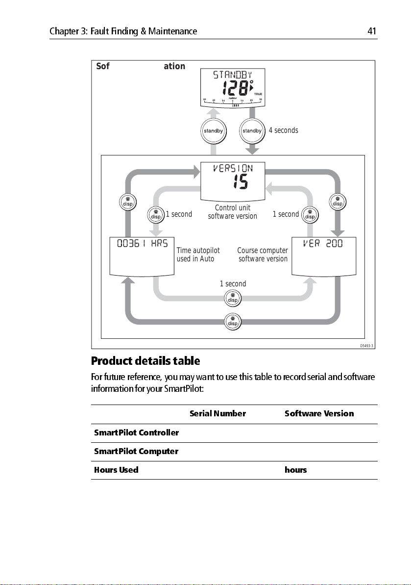
Chapter 3: Fault Finding & Maintenance 41
Software information
TRUE
4 seconds
software version
Time autopilot
used in Auto
Control unit
Course computer
software version
1 second1 second
1 second
D5493-3
Product details table
For futu re reference, you may want to use this tab le to record serial and software
information for your SmartPilot:
Serial Number Software V ersion
SmartPilot Contr oller
SmartPilot Compute r
Hours Used hours
Page 52

42 S1 Wheel and Tiller Pilots Operating Guide
Page 53
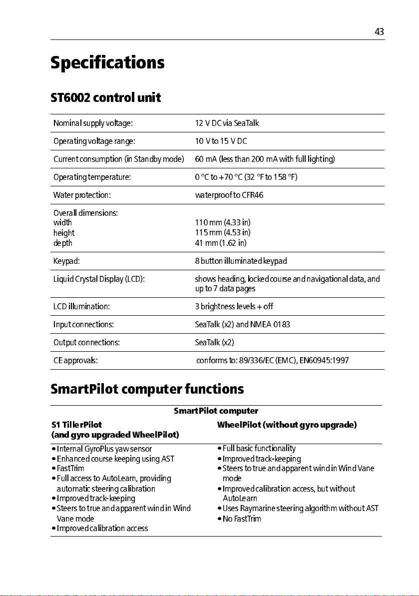
Specifications
ST6002 c ontrol unit
Nominal s upply voltage: 12 V DC via SeaT alk
Operating voltage r ange: 10 V to 1 5 V DC
Current con sumpt ion (in Standby m ode) 60 mA (less than 20 0 mA with fu ll lightin g)
Operating temperat ure: 0 °C to +70 °C (32 °F to 15 8 °F)
Water protection : waterproof to CF R46
43
Overall dimension s:
width
height
depth
Keypad: 8 button illum inated keypad
Liquid Crystal Display (LCD): s hows heading, locked cour se and navigational data, and
LCD illumination: 3 brightness levels + off
Input con nections: SeaTalk (x2) and NMEA 018 3
Output conn ections: SeaTalk (x2 )
CE approval s: conforms to: 89 /336/EC (EMC), EN60945:1 997
110 mm (4.33 in)
115 mm (4.53 in)
41 mm (1.62 in)
up to 7 data pages
SmartPilot computer f unctions
SmartPilot compute r
S1 TillerPi lot
(and gyr o upgraded Whe elPilot)
•Internal GyroPlus yaw sensor
•Enhanced course keeping using AST
•FastTrim
•Full access to AutoLearn , pro viding
automatic steering calibrat ion
•Improved trackkeeping
•Steers to true and apparen t wind in Wind
Vane mo de
•Improved calibration access
WheelPilot (wit hout gyro upgr ade)
•Full basic functionality
•Improved trackkeeping
•Steers to true and apparent wind in Wind V ane
mode
•Improved calibration access , but without
AutoLearn
•Uses Raymarine steering al gorithm without AST
• No FastTrim
Page 54

44 S1 Wheel and Tiller Pilots Operating Guide
Glossary
Term
AST Advanced Steering T echnology (AST) is Raymarine’s un ique advanced steering
AutoLearn Selflearning calibr ation featur e availab le on S1G , S2G an d S3G autopilo t sys
AutoT rim The AutoT rim setting determines the rate at which the autopilot applies ‘stand
AWG American Wire Gauge.
CE Marked on Raymar ine prod ucts th at compl y with defin ed Europ ean Commu
counter rud der Counter r udder is the am ount of rudd er the au topilot applies to try to pr event
CR pump Cons tant Ru nning h ydraulic p ump .
DC Direct current.
EMC
(Electromagnetic
Compatibility)
Meaning
algorithm. It uses inputs from a wide vari ety of sensors to tune the autopi lot’s
operation to pro vide superior contro l of the boat in any condition.
tems.
ing helm’ to correct for trim chang es caused by var ying wind loads o n the sails
or superst ructure.
nity standar ds.
the boat fro m yawing off course . Higher coun ter rudder sett ings result in more
rudder b eing appli ed.
When powered up, all electrical equipment produces electromagnetic fields .
These can cause adj acent pieces of electrical equipmen t to interact with one
another , an d this can degrade their perfor mance. By following th e EMC guide
lines in this h andbook, you can minimize t hese effects by ensurin g opt imum
Electromagnetic Comp atibility (EMC) between equipment.
Fluxgate Standard Raym arine comp ass s upplied with cours e computer core pack.
GPS Global P ositio ning Sys tem.
GyroPlus Raymarine’s GyroP lus yaw sensor that m easures t he boat’ s rate of turn. It is
built into the S1G , S2G and S3G course compu ters.
I/O drive I nboard/Ou tboard or stern dr ive.
MOB Man overb oard.
nm Nautical mile .
Page 55

Glossary 45
Term
NMEA The NMEA (Natio nal Maritime Electronics Associatio n) protocol is an interna
response The autopil ot respons e level controls t he relationship between course k eeping
rudder gain Rudder gain is a measure of h ow much helm the aut opilot will apply t o correct
SeaTalk SeaT alk is Raymarine’ s propriet ary commu nication s ystem. It links the p rod
SeaTalk bus T his refers to the con tinuous SeaT alk sys tem conn ecting tog ether a s eries of
SM Statute (land) mile .
VHF Very High F requency (radio).
WindT rim WindT rim (wind respons e) controls how quickly the autopilot resp onds to
XTE Cross track error .
Yaw
Meaning
tionally accepted serial commun ication interface standard for sh aring data
between electronic equipment. Raymarin e products can share informati on
with non SeaT alk equipment using the N MEA 018 3 pro tocol.
accuracy and the amoun t of h elm/driv e activity.
course erro rs . T he high er the s etting t he more r udder will be applied.
ucts to prov ide a sin gle, integrat ed syst em shari ng power and dat a.
Raymarine units .
changes in the wind direction. Higher wind trim settings will result in a pilot
that is more r esponsiv e to wind changes .
The boat’ s rate of turn (°/ sec).
Page 56

46 S1 Wheel and Tiller Pilots Operating Guide
Page 57

Index
47
A
Alarm
NEXT WPT
OFFCOURSE
SHALLOW
Alarms
CURRENT LIMIT
DRIVE ST OPPED
LARGE XTE
LOW BATT
LRN FAIL
MOB
MO T POW SWAPPED
NEXT WPT
NO DATA
NO PILO T
NO RUDREF
OFFCOURSE
RG F AIL
SEAT ALK FAIL 1 or 2
SEAT ALK/STLK FAI L
WINDSHIFT
Auto mode
AutoTack
Changing cour se
Dodging obs tacles
Offcourse alar m
AutoTack
in wind v ane mo de
C
Clutch (wheel drive) adjustm ent, 37
Contrast
Controller
Specifications
Course changes
Cross tr ack error
Explanation
LARGE XTE war ning
Current limit alarm
, 28,
,
28
, 11,
,
14
,
29
,
29
,
29
34
,
35
,
35
, 20,
28
,
35
,
35
,
35
,
22
,
35
,
35
,
35
,
9
,
36
,
36
,
36
,
25
,
6
,
11
,
7
,
8
,
9
30
,
25
,
43
,
7
,
18
, 20,
28
,
35
D
Data pages, 27
Display
,
Contrast
Illumination
Dodging obstacles
Drive stopped alarm
F
Fault finding, 33
Following a rou te
G
Glossary, 44–45
Gybe inhibit
GyroPlus fail alarm
H
Help lines, 40
I
Illumination, 14
K
Keypad
Illumination
Keypad fu nctions
L
Large XTE
Alarm
Learn fail alarm
Lighting
Low battery alar m
M
Maintenance, 36
Man Overboard alarm
MOB
Alarm
Motor/P ower s wapped alarm
N
Next WPT
Alarm
14
,
14
,
8
,
35
,
17
, 12,
30
,
36
,
14
,
3
,
28
,
35
,
14
,
35
,
28
,
28
,
29
,
35
Page 58

48 S1 Wheel and Tiller Pilots Operating Guide
Next WPT alarm, 22
No data alarm
No pilot alarm
No rudref alarm
O
Offcourse
Alarm
Description
P
Performan ce adjustment, 9
Gyro upgrad ed WheelPilot
TillerPilot
WheelPilot
Preventing gybes
Product suppo rt
R
Response level, 31
RG fail alarm
Route completed
S
Safety notices, i
T rack mode
Sailboats
AutoTack
Preventing gyb es
SeaTalk
SeaTalk fail 1 o r 2
SeaTalk fail alarm
Service
Settings
AutoTack
Gybe inhibit
Response lev el
User calibration
Wind type
WindTrim
Shallow
Alarm
SmartPilot
Disengaging
Engaging
Functions
Specifications
,
35
,
35
,
35
,
29
,
9
,
10
,
11
,
12
,
39
,
36
,
22
,
17
,
11
,
12
,
36
,
36
,
39
,
30
,
30
,
31
,
30
,
31
,
31
,
29
,
7
,
6
,
1
,
43
Standby Mode
Switching on/off
T
Technical su pport, 39
Track mod e
Cross track error
Dodge
Next waypoint
Route completed
Safety
,
10
Tidal compens ation
Waypoint names
U
User Calibration, 30
W
Waypoint
Advance
Advance w arning
Arrival
Skipping
Wheel drive
Clutch adjust ment
Maintenance
Wind angle
Adjusting
Wind type
Wind vane m ode
Adjusting wind ang le
Apparent wind
AutoTack
Dodge
Enabling
Operating hin ts
T rue wind
Wind shift warning
WindTrim
WindTrim
,
17
,
21
,
17
,
,
21
,
,
,
31
,
,
25
,
,
,
, 23,
21
22
24
,
25
24
23
23
31
7
,
3
,
18
,
22
,
22
,
20
,
27
,
22
,
37
,
37
,
23
,
24
,
23
,
26
,
25
 Loading...