


MK II Wheel
Drive
Installation Guide
Document number: 87063-1
Date: December 2005

MK II Wheel Drive 3
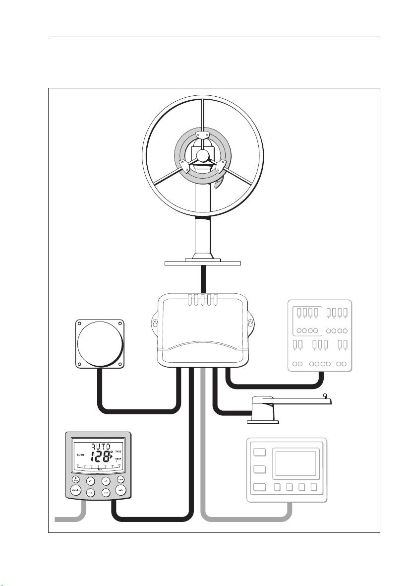
System layout
Wheel drive
Fluxgate compass
Control unit
Course computer
Boat's electrical
distribution panel
Rudder position sensor
NMEA
instrument
or navigator
D8908-1
4 MK II Wheel Drive
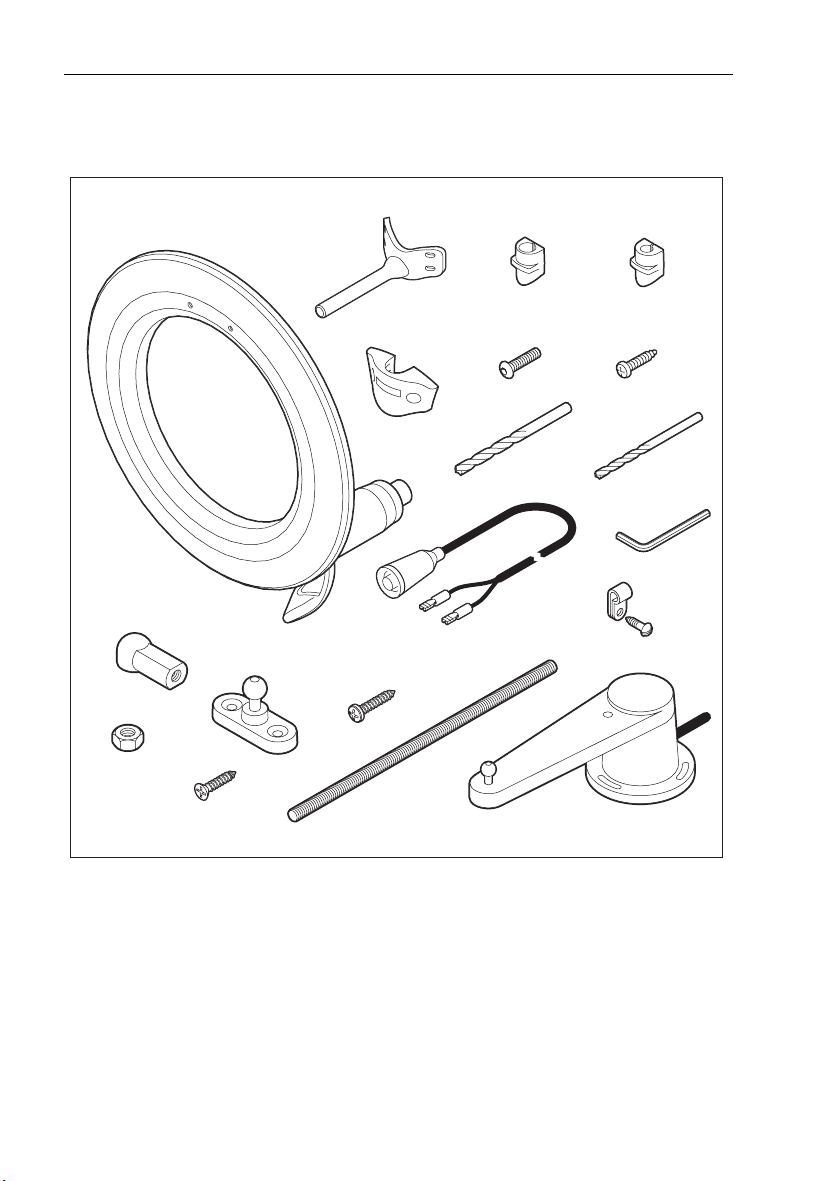
Parts supplied
Wheel drive parts
Wheel drive
Ball joint (x2)
Nut (x2)
Tiller pin
Pedestal bracket
Spoke clamp (x3)
No 8 x ¾ inch
Pan head screw (x3)
16 mm spoke
clamp insert (x3)
Clamp screw,
M5 x 16 mm (x6)
6 mm
drill bit
Stud
Power cable
4.5 m (15 ft)
12 mm spoke
clamp insert (x3)
Bracket screw,
No 10 x 3/4 in (x4)
4 mm
drill bit
3 mm
allen key
Cable clip
and screw,
No 6 x 1/2 in
Rudder position sensor
No 8 x ¾ inch
Countersunk head screw (x2)
Optional: Bulkhead/box pedestal fitting kit E15017 (if required)
D8885-1

MK II Wheel Drive 5
Tools required
1. Tape measure (metric/imperial)
2. Pliers and cross-head/pozi-drive screwdriver
3. Hammer and center punch
4. Pencil, masking tape
5. Spanner (Wrench) for the wheel nut
6. Washing-up liquid (to lubricate the spokes)
7. Hacksaw to cut the pedestal bracket
8. Power/battery Drill
9. 4 mm + 6 mm drill bits (supplied)
10. 3 mm allen key (Hex key, supplied)

6 MK II Wheel Drive
Wheel drive
The Raymarine wheel drive will fit 3, 4, 5, 6, 7 or 8 spoke wheels. It is designed to operate with
steering systems with between 1 to 3.5 turns lock to lock.
Clamp screw,
M5 x 16 mm (x6)
Wheel drive
front cover
Pre-drilled spoke
clamp holes (x2)
Bracket screw,
No 10 x 3/4 inch (x4)
Pedestal
bracket
Bracket pin
Cable plug
Cable socket
Motor tube
Spoke clamp (x3) Clamp insert (x3)
Wheel drive – main parts
Installation stages
Installing the wheel drive involves four steps:
1. Drilling the spoke clamp holes in the front cover.
2. Securing the wheel drive to the wheel.
3. Attaching the pedestal bracket.
4. Connecting the drive to the course computer.
Clutch lever
D8886-1
MK II Wheel Drive 7
Drilling the spoke clamp holes
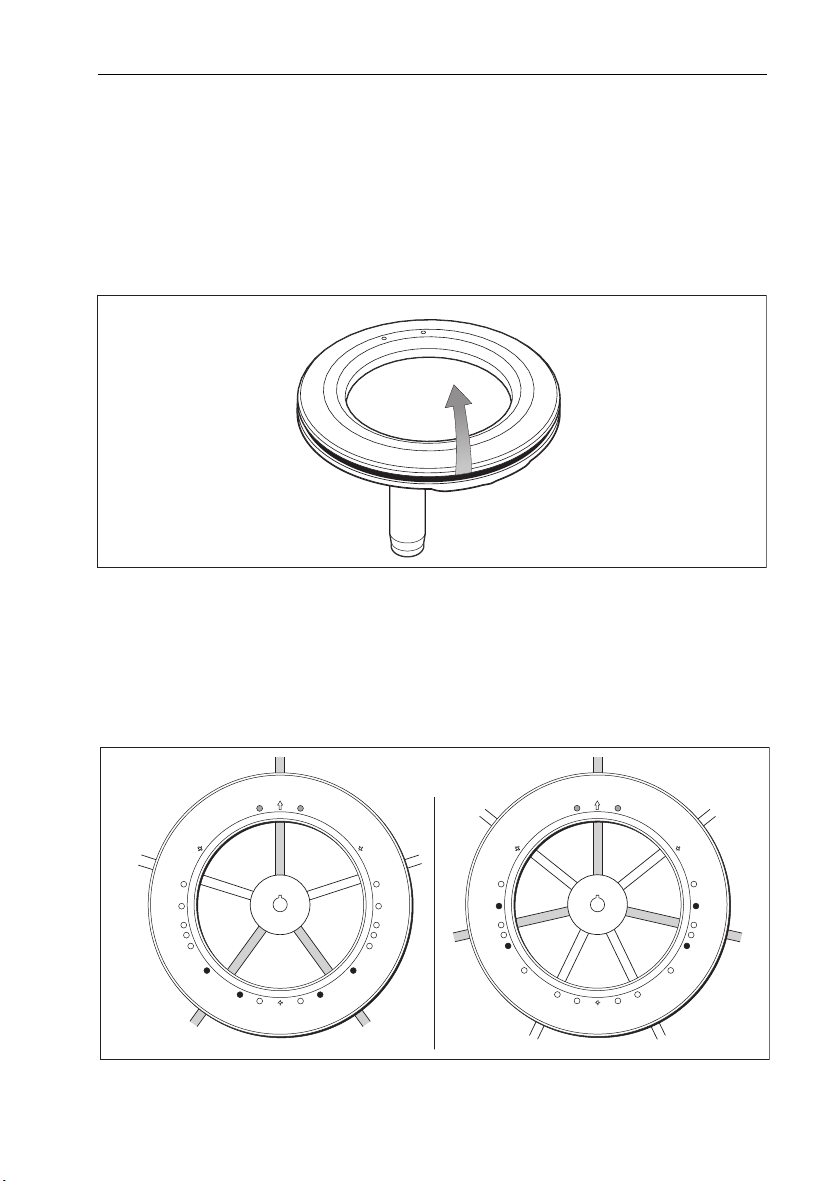
1. Remove the wheel drive front cover:
• the front cover is held onto the wheel drive by three ‘push-fit’ posts which sit in three
sockets on the drive ring
• to remove the cover, hold the motor in one hand and use your other hand to pull the
cover up and away from the drive unit (as shown below)
2. Identify the appropriate spoke clamp holes for your wheel. With the arrow at the top, refer
to the following diagrams:
• the holes are numbered inside the cover (e.g. if you have a 5 spoke wheel, you need to
drill the 4 locations marked with ‘5’)
• mark the appropriate spoke clamp holes and check them by holding the cover against
your wheel
5 spokes 7 spokes
Top 2 spoke clamp holes
are pre-drilled
D8888-1
D8889-1

8 MK II Wheel Drive
3 or 6 spokes 4 or 8 spokes
Note:
The wheel drive is designed to work with 3 spoke clamps on 4 or 8 spoke wheels. For cosmetic
Top 2 spoke clamp holes
are pre-drilled
reasons, however, you may want to fit an extra spoke clamp to the fourth spoke. Raymarine dealers can
supply an extra spoke clamp (part number A18089).
3. Drill the appropriate spoke clamp holes using the larger of the supplied drill bits (6.0 mm
1
or
/4in):
• drill from the inside, placing a piece of scrap wood under the cover to produce a clean
exit hole
• you will need to drill 4 new holes so the cover has 6 holes in total (2 for each spoke
clamp)
Note:
The spoke clamps will cover these exit holes, so they will not be visible when the wheel drive is
installed.
D8892-1
Piece of scrap wood
D8894-1
MK II Wheel Drive 9
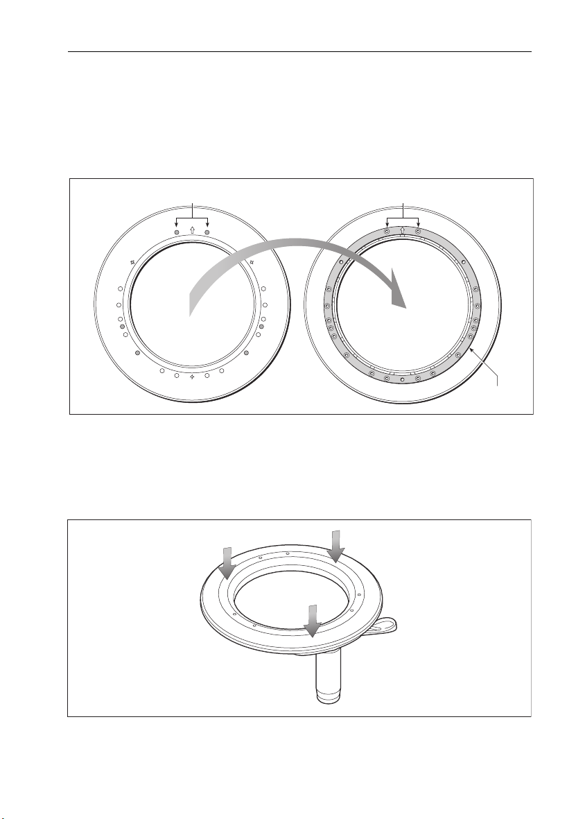
4. Align the cover with the wheel drive:
• the two pre-drilled holes (marked with an arrow) must line up with their matching pair
of threaded inserts on the drive ring (also marked with an arrow)
• make sure that the other spoke clamp holes align with their threaded inserts
Note:
The cover will only fit back onto the wheel drive when you have aligned the two parts correctly.
Pre-drilled holes
(marked with arrow)
Pair of threaded inserts
(marked with arrow)
Front cover Drive unit
5. Fit the cover back onto the wheel drive:
• press the cover in the three places shown on the diagram below to push each of the
posts back into its locating socket
Note:
This step is easier with the clutch engaged.
TOP
Drive ring
D8896-1
D8897-1
 Loading...