

Page 1

Distributed by
Any reference to Raytheon or
RTN in this manual should be
interpreted as Raymarine.
The names Raytheon and RTN
are owned by the
Raytheon Company.
Page 2

AUTOPILOT
Installation and Set Up
TYPE
100/300
Page 3

Page 4

Contents
3
Contents
Chapter 1: Introduction .......................................................................... 9
1.1 ST7000 Control Unit ................................................................. 10
1.2 ST6000 Control Unit ................................................................. 10
1.3 Course Computer ..................................................................... 11
1.4 Fluxgate Compass .................................................................... 11
1.5 Rotary Rudder Reference Transducer .......................................... 12
1.6 Linear Feedback Transducer ...................................................... 12
1.7 Type CR Interface Unit ............................................................... 12
1.8 Drive Systems.......................................................................... 13
Rotary Drive Units ..................................................................... 13
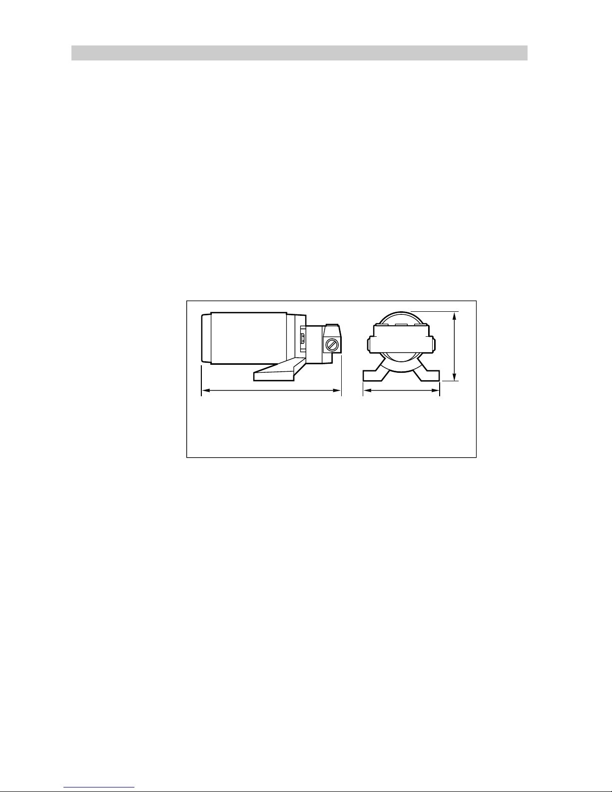
Reversing Hydraulic Pump ......................................................... 14
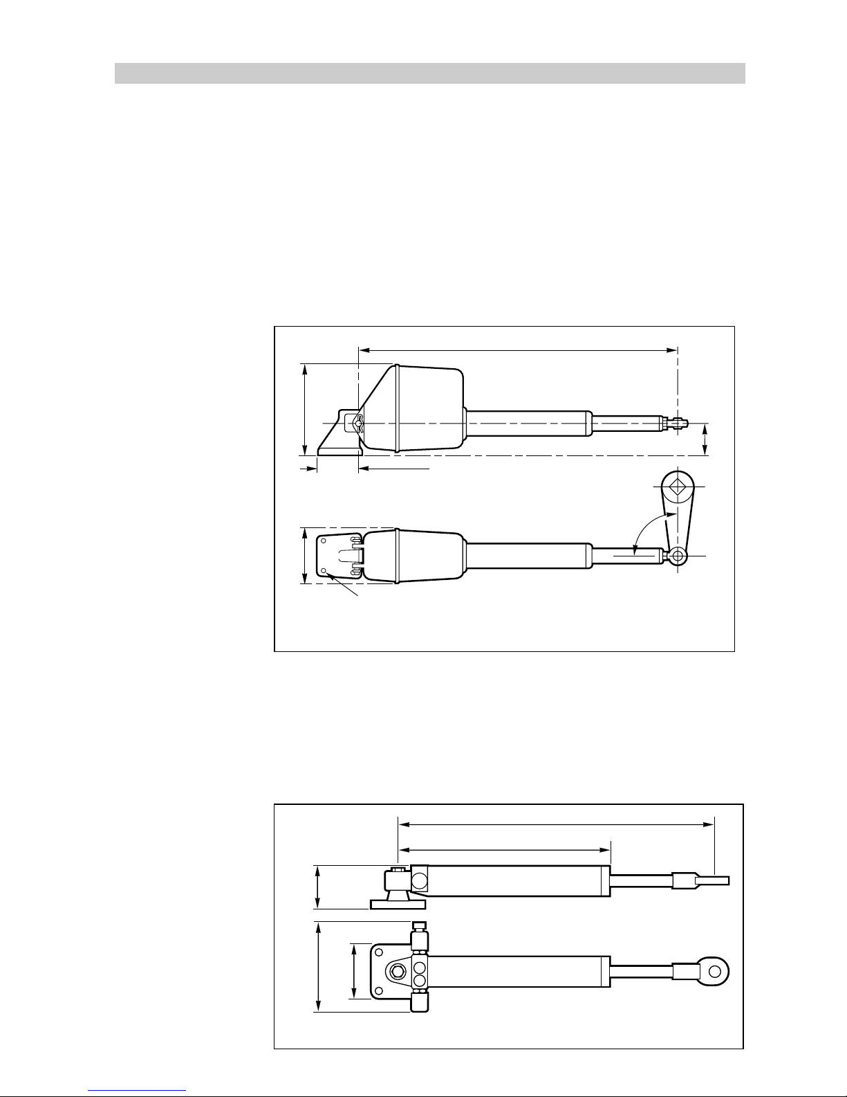
Linear Drive ............................................................................. 15
Hydraulic Linear ....................................................................... 15
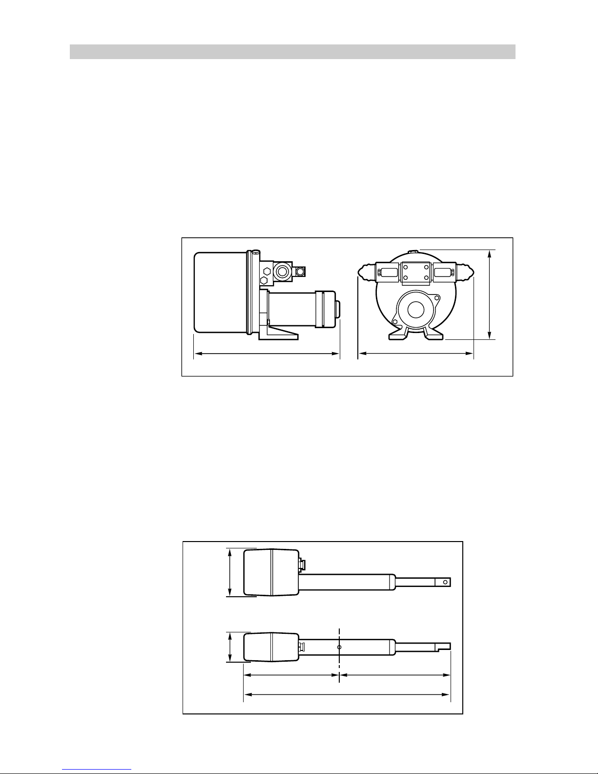
Constant Running Hydraulic Pump .............................................. 16
Stern drive............................................................................... 16
1.9 Options ................................................................................... 17
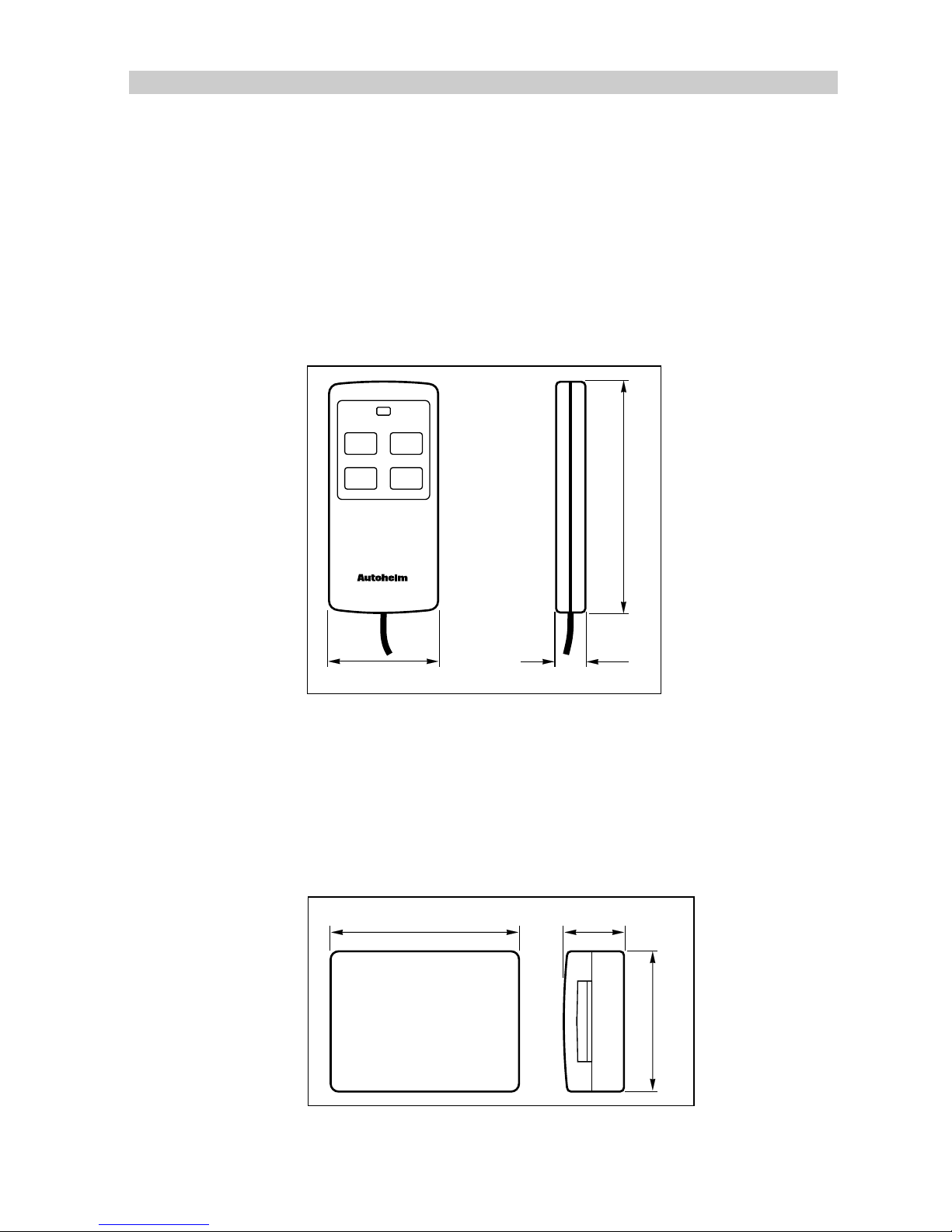
Hand-held Remote (Z101) .......................................................... 17
NMEA Interface (D153).............................................................. 17
Auxiliary Alarm (Z035) ............................................................... 18
Joystick (Z147) ........................................................................ 18
Wind Transducer (sail only) ......................................................... 19
Masthead Wind Transducer (Z080, Long Arm Version Z188) ...... 19
Pushpit Wind Transducer (Z087) ............................................ 19
Gyroplus Transducer (Z179) ...................................................... 20
Chapter 2: Installation .......................................................................... 21
2. General .................................................................................... 21
Planning the Installation ............................................................. 21
Page 5

4
TYPE100/300 Operation and Installation Handbook
2.1 Course Computer ..................................................................... 21
Mounting ................................................................................. 22
Cabling ................................................................................... 22
Type 1 Drive Units/Stern Drive/Constant Running Pump ............ 23
Type 2 Drive Units (12V) ........................................................ 23
Type 2 Drive Units (24V) ........................................................ 23
Type 3 Drive Units (12V) ........................................................ 24
Type 3 Drive Units (24V) ........................................................ 24
2.2 ST7000/6000 Control Unit........................................................ 25
Mounting ................................................................................. 25
Cabling ................................................................................... 26
2.3 Fluxgate Compass .................................................................... 28
Mounting ................................................................................. 28
Cabling ................................................................................... 29
2.4 Rotary Rudder Reference Transducer .......................................... 30
Mounting ................................................................................. 30
Cabling ................................................................................... 32
2.5 Linear Feedback Transducer ...................................................... 33
Mounting ................................................................................. 33
Cabling ................................................................................... 34
2.6 Hydraulic Drive Systems ............................................................ 35
Pump to Cylinder Specifications.................................................. 35
Reversing Hydraulic Pumps (Type 1, Type 2 & Type 3) ................... 35
Mounting ............................................................................ 35
Cabling............................................................................... 35
Type 1 Drive Unit ........................................................... 35
Type 2 Drive Unit (12V)................................................... 36
Type 2 Drive Unit (24V)................................................... 36
Type 3 Drive Unit (12V)................................................... 36
Type 3 Drive Unit (24V)................................................... 36
Page 6

Contents
5
Plumbing ............................................................................ 37
Two line system ................................................................... 39
Two line pressurised system.................................................. 39
Three line system ................................................................. 40
Bleeding the system ............................................................. 40
Constant Running Hydraulic Pump .............................................. 41
Mounting ............................................................................ 41
Cabling............................................................................... 42
Pump Cable ................................................................. 43
Solenoid Cable ............................................................. 43
Plumbing ............................................................................ 44
Hydraulic Linear Actuator........................................................... 45
Installation .......................................................................... 45
Cabling............................................................................... 48
Final Preparations Before use ................................................ 48
2.8 Mechanical Drive Systems ......................................................... 49
Rotary Drive Unit ...................................................................... 49
Mounting ................................................................................. 49
Cabling ................................................................................... 52
Type 1 Drive Unit.................................................................. 52
Type 2 Drive Unit (12V) ......................................................... 52
Type 2 Drive Unit (24V) ......................................................... 53
Linear Drive Unit ....................................................................... 53
Mounting ................................................................................. 54
Cabling ................................................................................... 55
Type 1 Drive Unit.................................................................. 55
Type 2 Drive Unit (12V) ......................................................... 55
Type 2 Drive Unit (24V) ......................................................... 56
Stern drive Actuator .................................................................. 56
Mounting ................................................................................. 56
Page 7

6
TYPE100/300 Operation and Installation Handbook
Volvo (Pre type 872215) ....................................................... 56
Volvo (Post type 872215) ..................................................... 58
Mercruiser/OMC/Yamaha ..................................................... 61
Mounting in a Restricted Area................................................. 63
Cabling ................................................................................... 64
2.9 Auxiliary Alarm ......................................................................... 65
Cabling ................................................................................... 65
2.10 Joystick ................................................................................ 66
Cabling ................................................................................... 66
2.11 Masthead Transducer (sail only) ................................................ 67
Mounting ................................................................................. 67
Cabling ................................................................................... 68
2.12 Interfacing to other manufacturer's equipment (NMEA) ................. 69
Course Computer NMEA ports ................................................... 69
Input Port ............................................................................ 69
Output Port ......................................................................... 70
Cabling............................................................................... 70
ST6000/ST7000 Control Unit NMEA Input ................................... 71
Cabling............................................................................... 72
NMEA Interface ........................................................................ 73
Cabling............................................................................... 74
Chapter 3: Functional Test ................................................................... 76
3.1 System test ............................................................................. 76
3.2 Switch-on ................................................................................ 76
3.3 Rudder angle sense .................................................................. 77
ST7000 control unit.................................................................. 77
ST6000 control unit.................................................................. 77
3.4 Rudder angle alignment ............................................................. 77
3.5 Operating sense ....................................................................... 78
3.6 Rudder deadband ..................................................................... 78
Page 8

Contents
7
3.7 Mechanical test (Linear, Rotary & Hydraulic Drives) ........................ 78
Current limit and cutout ............................................................. 78
3.8 Mechanical Test (Stern Drive) ..................................................... 79
3.9 Setting the Autopilot Rudder Limit (All drives) ................................. 79
3.10 GyroPlus Offset and Drift Compensation .................................... 80
Procedure ............................................................................... 80
Chapter 4: Calibration .......................................................................... 81
4.1 Recommended Settings ............................................................ 81
4.2 Selecting calibration.................................................................. 82
4. 3 Adj ust ing c ali brat ion.................................................................. 83
Rudder Gain............................................................................. 83
Rate Level ............................................................................... 84
Rudder Offset (Helm Adjust) ....................................................... 84
Rudder Limit ............................................................................ 84
Turn Rate ................................................................................ 85
Cruise Speed ........................................................................... 85
Off Course Limit ....................................................................... 85
Trim Level ............................................................................... 86
Joystick Mode (Manual Type) ...................................................... 86
Drive Option............................................................................. 86
Rudder Deadband (Rudder Damping) .......................................... 87
Magnetic Variation .................................................................... 87
Auto Adapt .............................................................................. 87
Latitude .................................................................................. 88
Wind Trim ................................................................................ 88
Response Level ........................................................................ 88
Auto Release (manual override) ................................................... 89
4.4 Saving Calibration Mode ............................................................ 89
4.5 Display Contrast Adjustment (ST7000 only) .................................. 90
4.6 Permanent Watch Alarm (SFIA) ................................................... 90
4.7 Recording Calibration Settings.................................................... 90
Page 9

8
TYPE100/300 Operation and Installation Handbook
Chapter 5: Initial Sea Trials................................................................... 91
5.1 Initial Sea Trials ........................................................................ 91
5.2 Automatic Compass Heading Alignment and Deviation Correction ... 91
5.3 Compass Alignment (without deviation correction) ......................... 93
5.4 First Sea Trials ......................................................................... 93
5.5 Response Control ..................................................................... 94
Level 1 - Automatic Sea State Control .......................................... 94
Level 2 - Automatic Sea State Inhibit ............................................ 94
Level 3 - Automatic Sea State Inhibit and counter rudder ................ 94
5.6 Automatic Trim Control ............................................................. 95
5.7 Rudder Gain Adjustment (Displacement Craft) ............................... 96
5.8 Rudder Gain Adjustment (High Speed Planning Craft) ..................... 97
5.9 Rudder Gain - Adjustment with Speed ........................................... 97
5.10 Manual Override (Stern Drive Actuators only) .............................. 98
Chapter 6: Track Control...................................................................... 99
Chapter 7: Windvane Control (Sail Only) ............................................. 101
Index .................................................................................................. 103
Page 10

Chapter 1: System Components
9
Chapter 1: Introduction
The Autohelm Type 100/300 autopilots are modular systems that can be
configured to suit the individual requirements of all types of vessels, using
a range of high efficiency rotary, linear or hydraulic rudder drive units to
match various types of steering systems.
The Autohelm system in its most basic form consists of a control unit,
course computer, drive unit, fluxgate compass and a rudder
reference transducer.
A full range of accessories are also available and include:
• Joystick (manual steering unit)
• Main alarm and interface
• Rate gyro
• Hand held remote control unit
• SeaTalk instrumentation
• Interface leads
Control
Unit
Control
Unit
Drive Unit
Rudder
Reference
Unit
Gyro
Fluxgate
Compass
Course
Computer
Cable
Clamp
D726-1
Page 11
10
TYPE 100/300 Operation and Installation Handbook
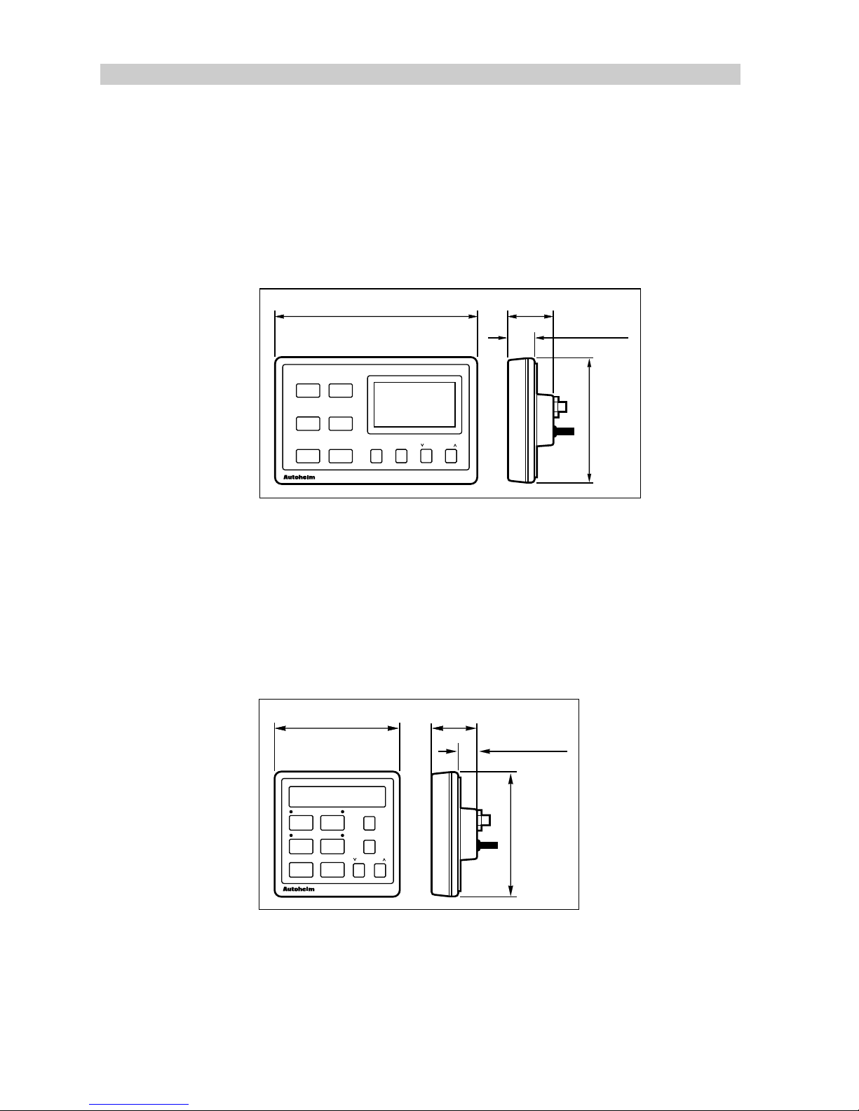
1.1 ST7000 Control Unit
The ST7000 control unit is fully weather protected and designed for above
or below deck istallation. The unit is connected to the course computer via
the SeaTalk bus. NMEA navigation, speed and wind information can be
received via a fixed socket on the rear of the case.
Note:
Additional control units can also be connected via the SeaTalk bus.
ST7000
●
●
●●
–1
–10
+
1
+
10
STAND BY AUTO DISPLAY TRACK RESPONSE
110mm
(4.33in)
24mm (0.95in)
177.8mm (7in)
38.75mm (1.5in)
D727-1
TM
1.2 ST6000 Control Unit
The ST6000 control unit, like the ST7000, is fully weather protected and
also designed for above or below deck installation. The unit is connected
to the course computer via the SeaTalk bus. NMEA navigation, speed and
wind information can be received via a fixed socket on the rear of the case.
Note:
Additional control units can also be connected via the SeaTalk bus.
–1
–10
+
1
+
10
STAND BY
AUTO
ST6000
DISPLAY
TRACK
RESPONSE
110mm
(4.33in)
24mm(0.95in)
110mm (4.33in) 38.75mm (1.5in)
D728 -1
TM
Page 12
Chapter 1: System Components
11
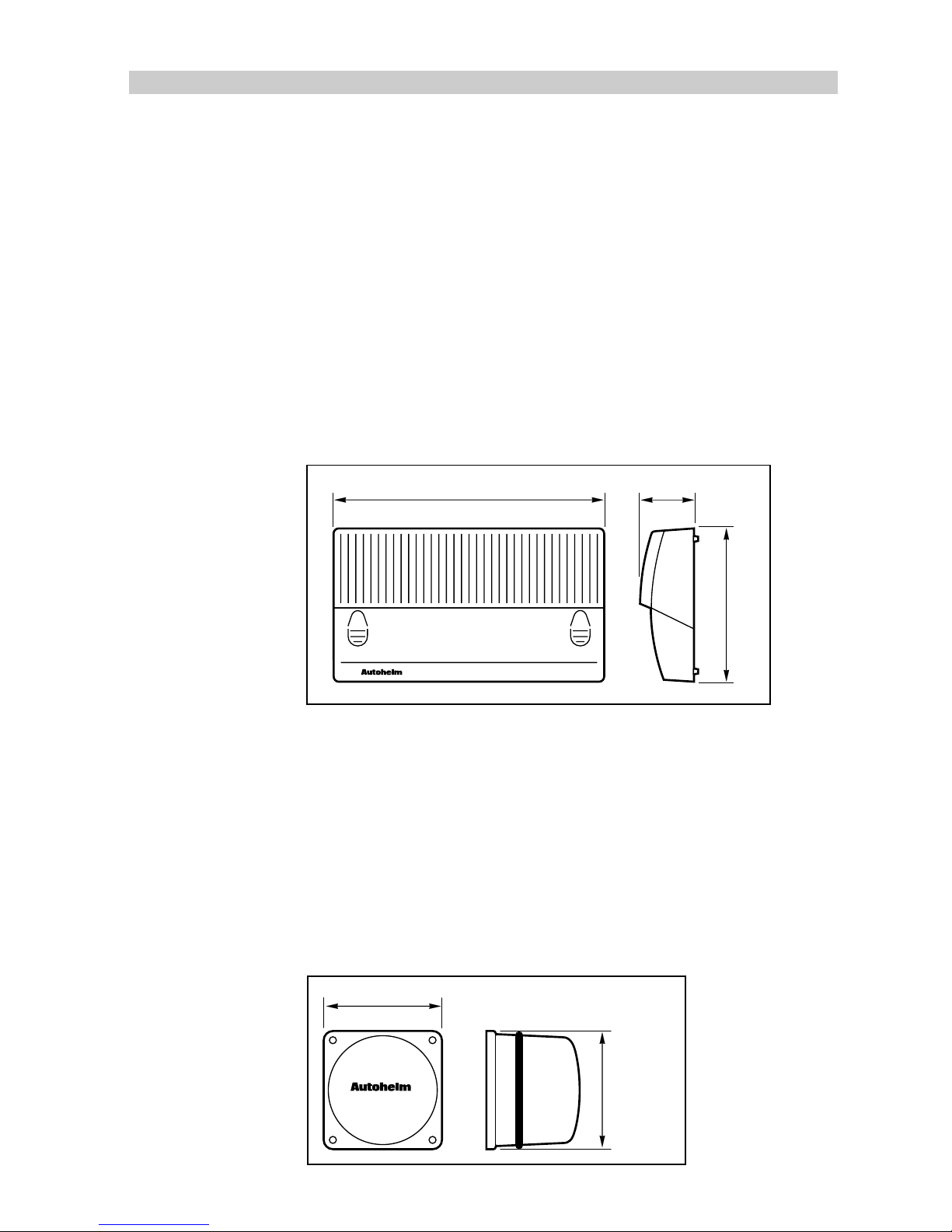
1.3 Course Computer
The course computer, available in both 12V or 24V versions, houses a
microprocessor, drive unit electronic control circuitry and power amplifier.
It is the central distribution point for the autopilot, electrical wiring and
ship’s power connection point.
The course computer also has NMEA input and outputs to allow operation
with other manufacturer's equipment.
The unit is only splash proof and must, therefore, be installed in a dry,
protected location.
Type 100 is used for Type 1 and Type CR 12V drives. Type 300 is used
with Type 2 and Type 3 drives.
45mm (1.8in)
233mm (9.2in)
130mm (5.1in)
D865-1
1.4 Fluxgate Compass
The fluxgate compass contains a gimbal mechanism that permits
accurate readings with pitch and roll movements up to +/- 35 degrees.
The compass is designed for below deck, bulkhead mounting and
connects directly to the course computer.
On steel decked vessels the compass can be mounted above deck,
however, autopilot performance may be affected due to the increased
motion.
76mm (3in)
76mm (3in)
D729-1
TM
Page 13
12
TYPE 100/300 Operation and Installation Handbook
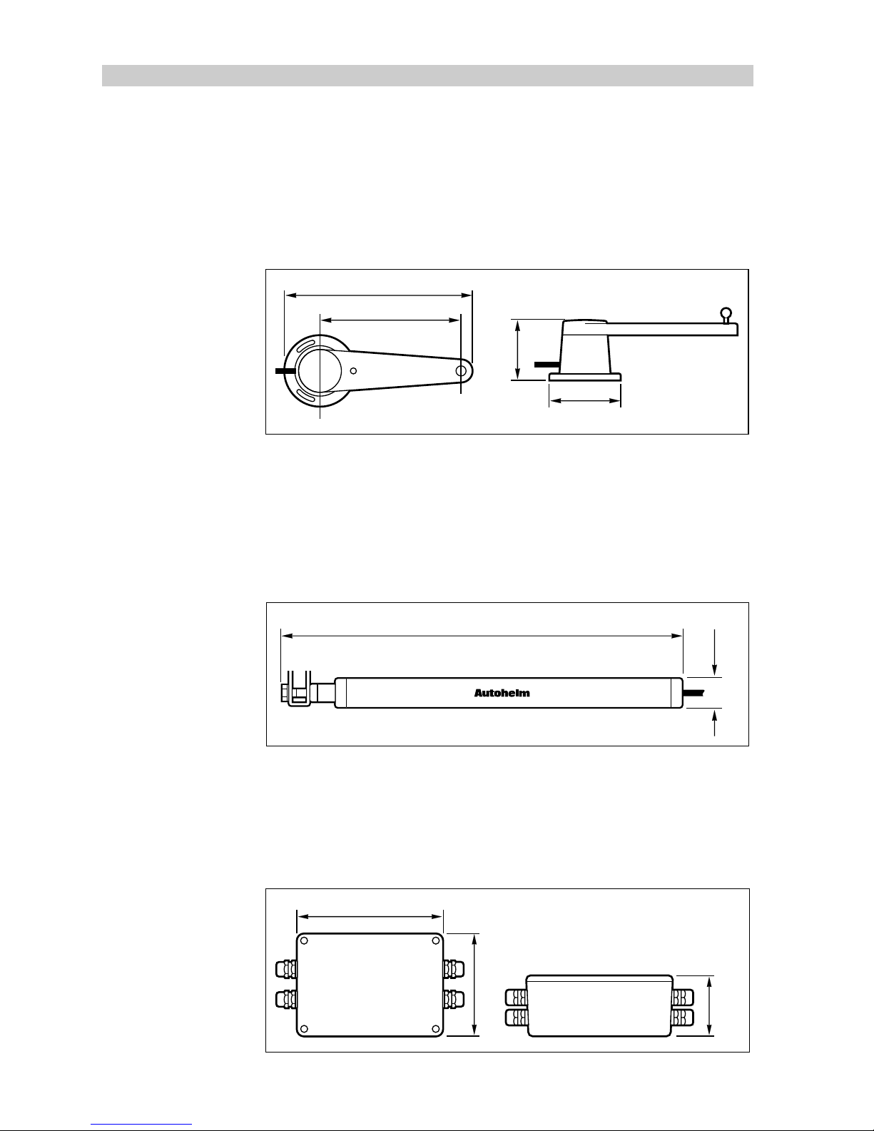
1.5 Rotary Rudder Reference Transducer
The rudder reference transducer provides the course computer with the
precise position of the vessels rudder. The unit is mounted on a suitable
base adjacent to the rudder stock. Its use is mandatory on all installations,
except when a linear rudder reference transducer is connected.
139.7mm (5.5in)
152mm (6in)
69.5mm (2.7in)
61mm (2.4in)
D730-1
1.6 Linear Feedback Transducer
The linear feedback transducer is designed for installations on ‘bullhorn’
style hydraulic outboard steering systems. The unit is totally weather proof
and mounted on the bullhorn ram. Its use is mandatory on all hydraulic
outboard installations.
425mm (16.75in)
32mm (1.3in)
D869-1
TM
1.7 Type CR Interface Unit
The course computer can be connected to the solenoids on a constant
running hydraulic pump using the type CR interface. The unit also provides
connections to energise a solenoid operated bypass valve.
125mm (5.9in)
100mm (3.95in)
60mm
(2.37in)
D734-1
Page 14
Chapter 1: System Components
13
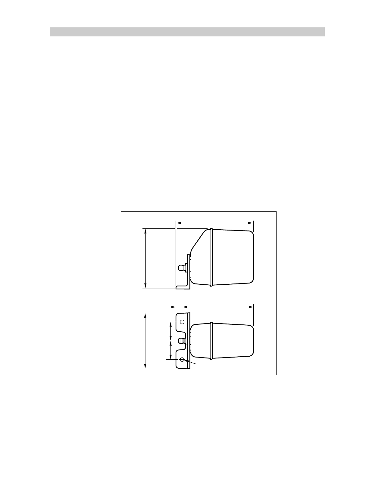
1.8 Drive Systems
A range of mechanical (rotary, linear and stern drive) and hydraulic drive
units are available for use with the Type 100/300 system. Rotary drives
are coupled to the steering system by a simple chain drive, linear drives
directly to the rudder stock at the tiller arm radius and stern drives directly
to the power steering valve block.
The type of hydraulic drive used is dependent on the size of the vessels
hydraulic cylinder.
Rotary Drive Units
Autohelm rotary drive units provide smooth, powerful steering commands
with almost silent operation. A rugged electric motor drives a precision
epicyclic gearbox via a high tensile drive belt. An electronic clutch
transmits high torque loads with no slippage. The drive unit can be
mounted in any attitude to simplify installation.
274mm (10.8in)
195mm
(7.7in)
256mm (10in)
20mm (0.8in)
184mm
(7.2in)
60mm
(2.4in)
60mm
(2.4in)
D736-1
2 holes 12.5mm (0.5in) diameter
Page 15
14
TYPE 100/300 Operation and Installation Handbook
Reversing Hydraulic Pump
The reversing hydraulic pump consists of a precision gear pump and an
integral check valve block driven by a continuously rated servo motor. The
pump is connected directly to the vessels steering cylinder, with the
course computer regulating the peak pump pressure.
There are three types of pump: type 1, type 2 and type 3. The different
type relates to the steering ram capacity, which is directly related to the
displacement of the vessel.
Type 1: 80 to 230 cc (4.9 to 14cu in)
Type 2: 160 to 350 cc (9.8 to 21cu in)
Type 3: 250 to 460 cc (15 to 28cu in)
'A'
117mm (4.62in)
103mm (4.07in)
D738-1
Pump Dimension 'A'
Type 1 177mm (6.96in)
Type 2 177mm (6.96in)
Type 3 235mm (9.25in)
Page 16
Chapter 1: System Components
15
Linear Drive
The Autohelm linear drive unit is of outstanding design which features
powerful thrust, fast hard overtimes and near silent operation. When
backdriven the movement is smooth with minimal backdriven force. Using
a high tensile belt drive and epicyclic reduction gearbox the powerful
electric motor is controlled by an electronic fail-safe clutch.
The design is highly efficient and provides high performance for minimum
current consumption.
90°
D1010-1
A
4 off fixing holes suitable
for 10mm (0.4in) bolts
79mm (3.1in)
114mm (4.5in)
197mm (7.8in)
50mm (2in)
Drive Dimension 'A'
Type 1 700mm (27.5in)
Type 2 (short) 700mm (27.5in)
Type 2 (long) 850mm (33.5in)
Hydraulic Linear
The hydraulic linear drive unit is a self contained secondary steering
cylinder (with a built-in solenoid bypass valve). The unit is driven by a
reversing hydraulic pump to provide a totally isolated autopilot steering
system.
D877-1
101.6mm (4in)
152mm (6in)
80mm
(3.15in)
457mm (18in)
A
Drive Dimension 'A'
Type 2 540mm (21.25in)
Type 3 690mm (27.15in)
Page 17
16
TYPE 100/300 Operation and Installation Handbook
Constant Running Hydraulic Pump
When steering loads require a ram capacity of over 460cc (28cu in) the
constant running hydraulic pump provides the ideal autopilot drive system.
Hydraulic fluid is supplied from a self contained reservoir and flow to the
steering ram is controlled by integral solenoid operated valves.
Used with a solenoid operated bypass valve and a separate hydraulic ram,
this system is recommended for heavy duty applications on large
mechanically steered vessels.
356mm (14in)
262mm (10.3in)
224mm (8.8in)
D740-1
Stern drive
The stern drive actuator must only be used on stern drives with cable
operated, power assisted steering.
The drive unit operates the power steering valve in exactly the same way
as the steering cable. A clutch disengages the drive unit to allow manual
steering when the autopilot is disengaged.
Installation kits are available for most popular types of steering manufacturers.
220mm (8.66in)
240mm (9.45in)
460mm (18.1in) mid-stroke
102.5mm
(4.0in)
63.4mm
(2.5in)
D743-1
Page 18
Chapter 1: System Components
17
1.9 Options
The Type 100/300 autopilot system is available with the following optional
system components:
Hand-held Remote (Z101)
The hand-held remote allows course changing from a position away from
the steering station. The hand held remote is connected to the autopilot via
the SeaTalk bus.
10
10
–
+
+
–
1
1
TM
65mm (2.5in) 14.5mm (0.6in)
138mm (5.4in)
D1011-1
NMEA Interface (D153)
Although the Type 100/300 has its own NMEA 0183 input and output
ports, you may wish to receive information from additional equipment
transmitting NMEA. The NMEA interface connects to the SeaTalk bus and
converts incoming data to SeaTalk. The interface also converts SeaTalk
data to NMEA 0183 format.
117.5mm (4.6in) 37mm (1.5in)
87.5mm (3.4in)
D873-1
Page 19
18
TYPE 100/300 Operation and Installation Handbook
Auxiliary Alarm (Z035)
The autopilot is provided with a comprehensive automatic off-course alarm
system that sounds from all control units. This provides sufficient audible
warning under most conditions. However, in cases where a high powered
alarm is required, an auxiliary alarm can be fitted. The auxiliary alarm is
connected to the SeaTalk bus via the NMEA interface box and will sound
whenever the autopilot transmits one of the following alarm conditions.
• Autopilot Off Course
• Watch Alarm
• Wind Shift
• Low Battery
• Large Cross Track Error
• NMEA Data Error
• No Autopilot Actuator Connected
• Stern drive Auto Release
• Waypoint Change Alarm
45mm (1.8in)85mm (3.35in)
D732-1
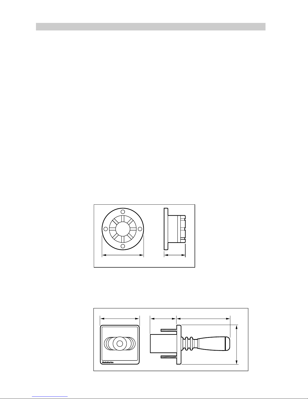
Joystick (Z147)
The Joystick is an electro mechanical remote steering unit that uses the
course computer and its drive unit to power steer the vessels rudder.
JOYSTICK
110mm (4.3in)
76mm (3in)
157mm (6.2in)
110mm (4.3in)
D734a-1
TM
Page 20
Chapter 1: System Components
19
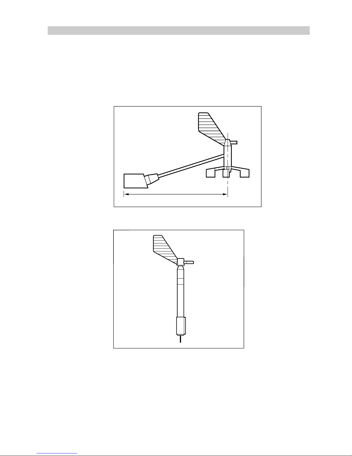
Wind Transducer (sail only)
If the installation does not include a SeaTalk Wind instrument either the
masthead or pushpit wind transducer can be connected directly to the
NMEA interface box to supply wind angle information.
Masthead Wind Transducer (Z080, Long Arm Version Z188)
371mm (14.6in)
D733-1
Pushpit Wind Transducer (Z087)
D1075-1
Page 21
20
TYPE 100/300 Operation and Installation Handbook
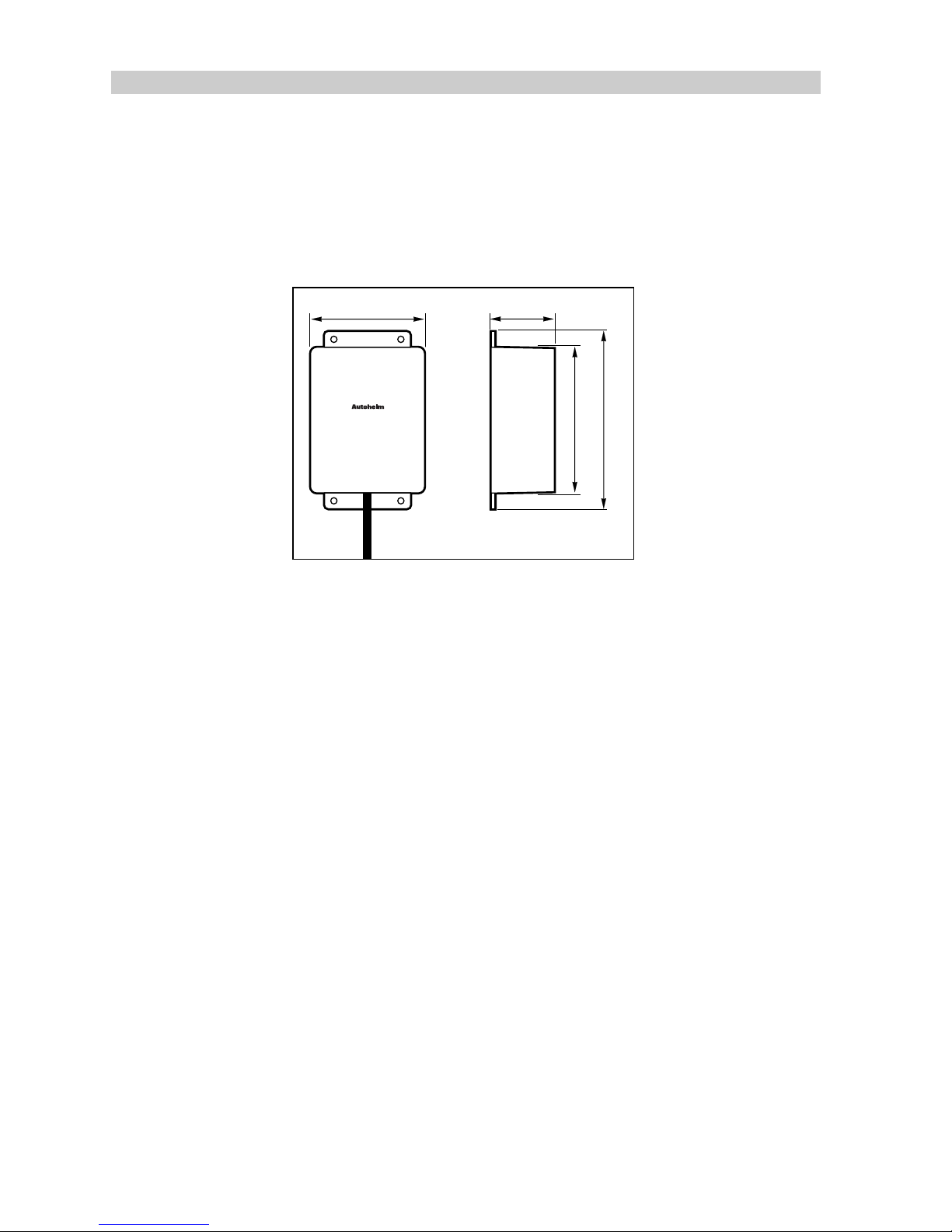
Gyroplus Transducer (Z179)
The Autohelm Gyroplus is a transducer that measures the rate of turn of
the vessel. This is used by the autopilot to give even better correction for
boat yaw in adverse weather conditions. It is particularly beneficial
downward and in following sea conditions.
140mm (5.5in)
115mm (4.5in)
51mm (2in)
90mm (3.5in)
D872-1
GYROPLUS
TM
Page 22

Chapter 2: Installation
21
Chapter 2: Installation
2. General
This section describes how to install the autopilot and system components
described in chapter1.
Planning the Installation
When selecting power cable it is important to use the stated wire gauge.
The cable you choose may meet the required current specification,
however, if too small, the voltage will drop between the supply and the
course computer. This will reduce the power of the drive unit and may
cause the electronics to malfunction.
2.1 Course Computer
The course computer must be located in a dry, protected location free
from high operating temperatures and excessive vibration. The unit must
be mounted vertically with free air flow to allow heat dissipation from the
power amplifier.
Avoid mounting the course computer:
• in an engine room
• where there is water splash/spray from bilge’s or hatches
• where it can be subjected to physical damage from heavy items (such
as hatch covers, tool boxes etc.)
• where it will be covered by other on-board equipment
• where it will be close to sources of high RF energy transmissions
(generators/SSB radios/ antenna cables etc.)
Page 23
22
TYPE 100/300 Operation and Installation Handbook
Mounting
D881-1
Vertical
1. With the course computer located as required, outline the two
mounting holes.
2. Drill two pilot holes for the fixing screws.
3. Secure the course computer to the vessel using the two screws
provided.
Note:
If the mounting surface is less than 3mm (1/8in) thick, use the U
clips provided.
4. Drill three pilot holes for the cable clamp bar.
5. Secure the cable clamp as shown.
Cabling
Note:
If you are installing the Type 100/300 system with a constant
running hydraulic pump, refer to page 40 before running the power cable.
1. Having sited the course computer, measure the total cable length
between the course computer and the vessels central power
distribution panel. Using the following tables, select the appropriate
cable size and circuit breaker relative to the type of drive unit used.
Page 24

Chapter 2: Installation
23
Type 1 Drive Units/Stern Drive/Constant Running Pump
Cable Length
(Distribution
panel to Course Computer)
Cable Gauge Copper Area
Up to 3m (10ft) 12 AWG 2.5 mm
Up to 5m (16ft) 10 AWG 4 mm
Up to 7m (23ft) 8 AWG 6 mm
Up to 10m (32ft) 6 AWG 10 mm
Up to 16m (52ft) 4 AWG 16 mm
81004-01
Type 2 Drive Units (12V)
Cable Length
(Distribution
panel to Course Computer)
Cable Gauge Copper Area
Up to 5m (16ft) 8 AWG 6 mm
Up to 7m (23ft) 6 AWG 10 mm
Up to 16m (52ft) 4 AWG 16 mm
81004-02
Type 2 Drive Units (24V)
Cable Length
(Distribution
panel to Course Computer)
Cable Gauge Copper Area
Up to 3m (10ft) 12 AWG 2.5 mm
Up to 5m (16ft) 10 AWG 4 mm
Up to 7m (23ft) 8 AWG 6 mm
Up to 10m (32ft) 6 AWG 10 mm
Up to 16m (52ft) 4 AWG 16 mm
81004-01
Page 25
24
TYPE 100/300 Operation and Installation Handbook
Type 3 Drive Units (12V)
Cable Length
(Distribution
panel to Course Computer)
Cable Gauge Copper Area
Up to 5m (16ft) 8 AWG 6 mm
Up to 7m (23ft) 6 AWG 10 mm
Up to 16m (52ft) 4 AWG 16 mm
81004-02
Type 3 Drive Units (24V)
Cable Length
(Distribution
panel to Course Computer)
Cable Gauge Copper Area
Up to 5m (16ft) 8 AWG 6 mm
Up to 7m (23ft) 6 AWG 10 mm
Up to 16m (52ft) 4 AWG 16 mm
81004-02
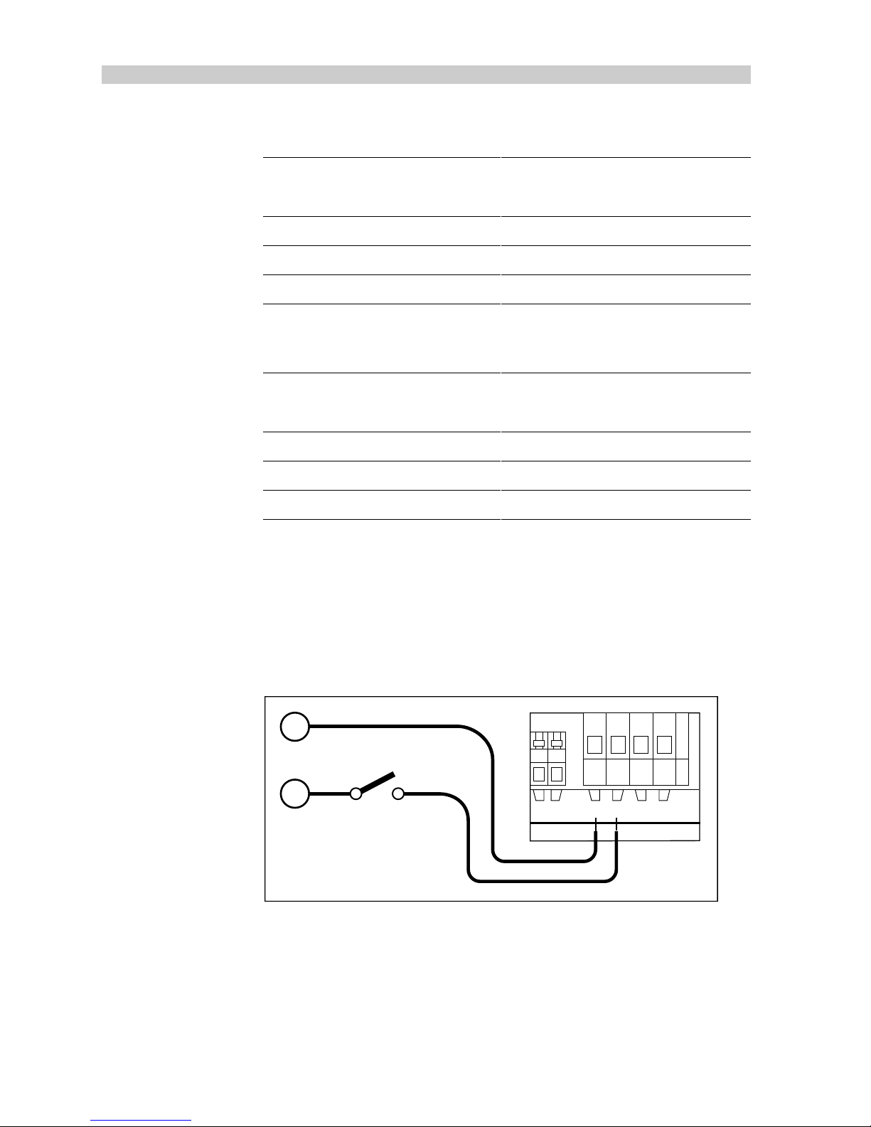
2. Remove the connector cover from the course computer.
3. Connect the power supply cable to the course computer power
terminals.
Note:
The cable must be protected by a circuit breaker
(see table for size).
Power
Supply
Circuit
breaker
D882-1
CLUTCH MOTORPOWER
+–+ –
12
–
+
Page 26
Chapter 2: Installation
25
Drive Unit Circuit Breaker Size
Type 1 25
Type 2 (12V) 40
Type 2 (24V) 25
Type 3 40
Sterndrive 25
Type CR 25
81004-03
2.2 ST7000/6000 Control Unit
The ST6000 and ST7000 control units are identical in operation and
installation.The main ST7000/6000 control unit should be mounted close
to the steering station where it is:
• normally viewed straight on for the best display legibility
• well protected against physical damage
• at least 9in (230mm) from a compass
• at least 20in (500mm) from radio receiving equipment
• accessible from behind to install and run cables
Note:
The rear case is designed to breathe through a small duct in the
cable boss to prevent the accumulation of moisture. Direct exposure to
the rear of the control unit must be avoided.
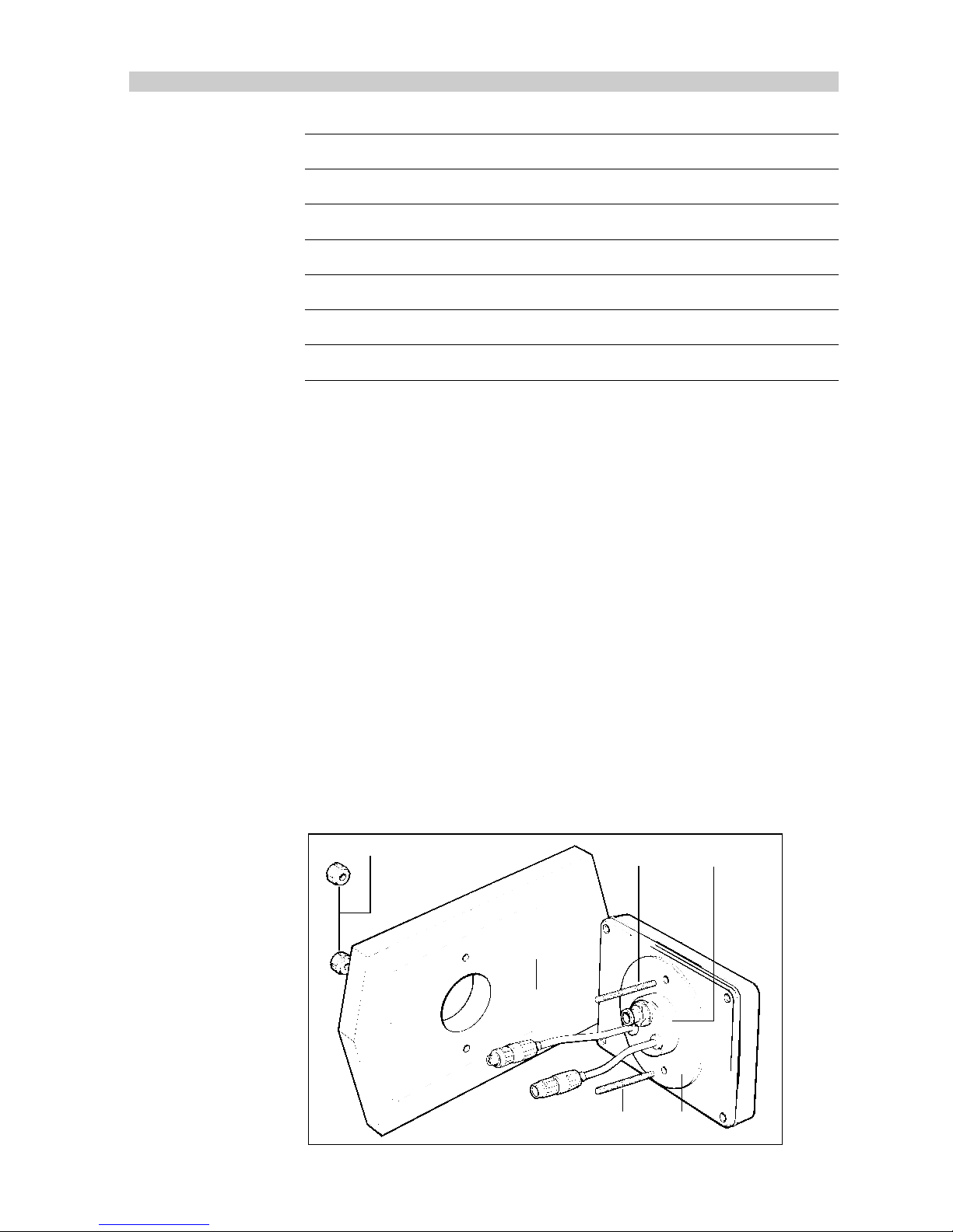
Mounting
13
42
2
D746-1
1 Cable boss 2 Fixing stud 3 Thumb nut 4 Sealing gasket
Page 27
26
TYPE 100/300 Operation and Installation Handbook
1. Make sure that the mounting surface is smooth and flat.
2. Use the template provided to mark the centres for the two fixing studs
and the cable boss.
Note:
Adjacent instruments should have 6mm (1/4in) separation to allow
room for the protective covers.
3. Drill two 4mm (5/32in) diameter holes.
4. Using a 50mm (2in) diameter cutter, drill the hole for the cable
boss (1).
5. Screw the two fixing studs (2) into the rear case of the control unit.
6. Pass the cable tails through the large hole and secure the control unit
with the thumb nuts (3) provided.
Note:
The sealing gasket (4), is already attached to the rear case of the
control unit.
Cabling
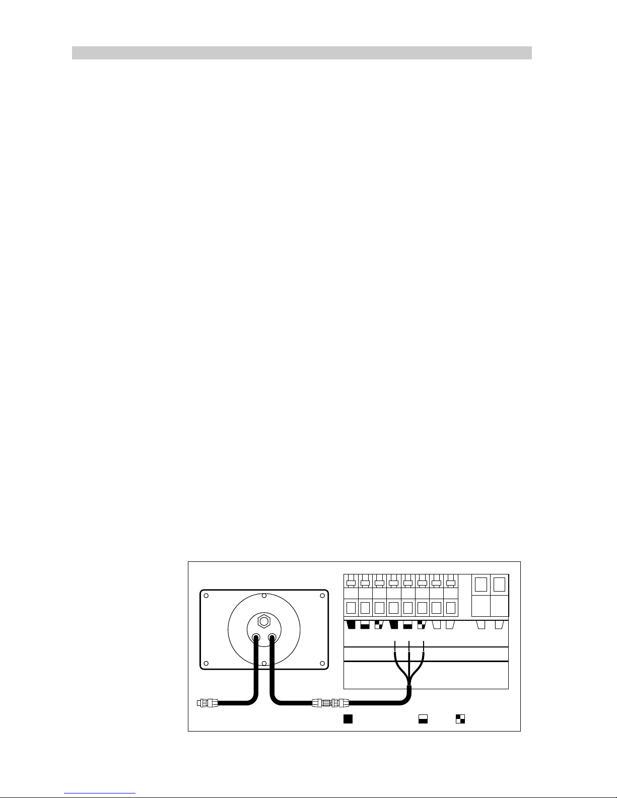
The control unit is provided with a SeaTalk cable fitted with a 3 pin socket
on each end.
1. Plug one end of the cable into one of the two SeaTalk sockets on the
back of the control unit.
2. Run the SeaTalk cable back to the course computer.
Note:
If more than one control unit is fitted, the SeaTalk cable can be
connected to the free SeaTalk socket on the first control unit.
3. Cut the remaining plug from the SeaTalk cable and connect to the the
SeaTalk terminals on the course computer (as shown in the following
illustration).
SeaTalk SeaTalk CLUTCH POWER
+–+–
D1012-1
Grey (screen) Red Yellow
Page 28
Chapter 2: Installation
27
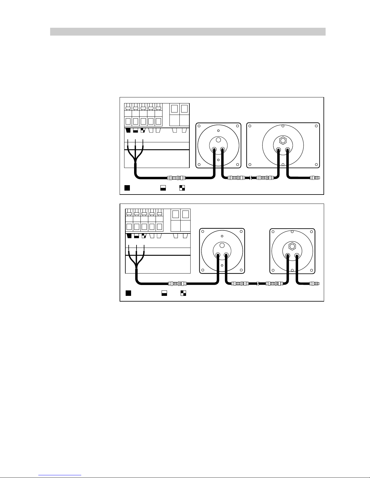
If the vessel is already fitted with Autohelm instrumentation, this should be
connected to the course computer as shown, using one of the standard
SeaTalk interface cables. The course computer will then supply power for
the complete system.
D1013-1
+
+
+
+
+
+
+
+
+
+
ST50 Instrument ST7000 Control Unit
SeaTalk CLUTCH POWER
+–+–
Grey (screen) Red Yellow
+
+
+
+
+
+
D1014-1
+
+
+
+
ST50 Instrument ST6000 Control Unit
SeaTalk CLUTCH POWER
+–+–
Grey (screen) Red Yellow
Page 29
28
TYPE 100/300 Operation and Installation Handbook
2.3 Fluxgate Compass
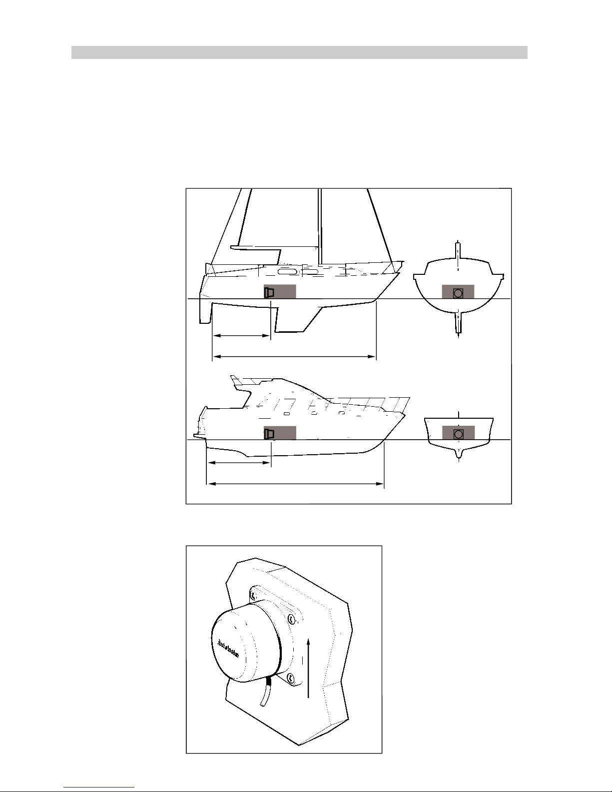
Correct positioning of the fluxgate compass is crucial if ultimate performance is to be achieved. To minimise gimbal disturbance, the fluxgate
should ideally be positioned as near as possible to the pitch and roll centre
of the vessel.
0.3L to 0.5L
L
0.3L to 0.5L
L
X
X
Y
Y
D194-2
Mounting
D193-2
Vertical
Page 30
Chapter 2: Installation
29
1. Locate the fluxgate compass on a suitable vertical surface.
2. Drill four pilot holes and attach the fluxgate compass using the selftapping screws provided.
3. Make sure that the fluxgate is positioned at least 0.8m (2ft 6in) away
from the vessel’s steering compass in order to avoid deviation of both
compasses. To avoid compass deviation and reduction in sensitivity
of the sensor, the fluxgate must also be positioned as far away as
possible from large iron masses.
Note:
If any doubt exists over magnetic suitability of the chosen site, the
position may be surveyed using a simple hand bearing compass. The hand
bearing compass should be fixed in the chosen position and the vessel
swung through 360 degrees. Relative differences in reading between the
hand bearing compass and the vessel’s main steering compass should,
ideally, not exceed 10 degrees on any heading.
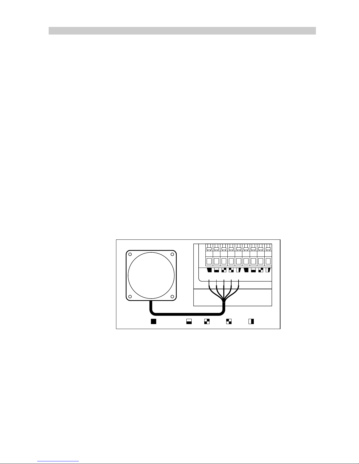
Cabling
1. Run the cable back to the course computer.
2. Connect the to the fluxgate terminals on the course computer.
D890-1
FLUXGATE
JOYSTICK
Grey (screen) BlueRed YellowGreen
Note:
A 10m (30ft) extension cable is available for larger installations
(part no. D174).
Page 31
30
TYPE 100/300 Operation and Installation Handbook
2.4 Rotary Rudder Reference Transducer
The rotary rudder reference transducer must be connected directly to the
tiller arm to provide accurate rudder position to the course computer. If it
is more convenient, the unit may be installed upside down. However, if
mounted this way, the red and green wires must be reversed at the
course computer.
Mounting
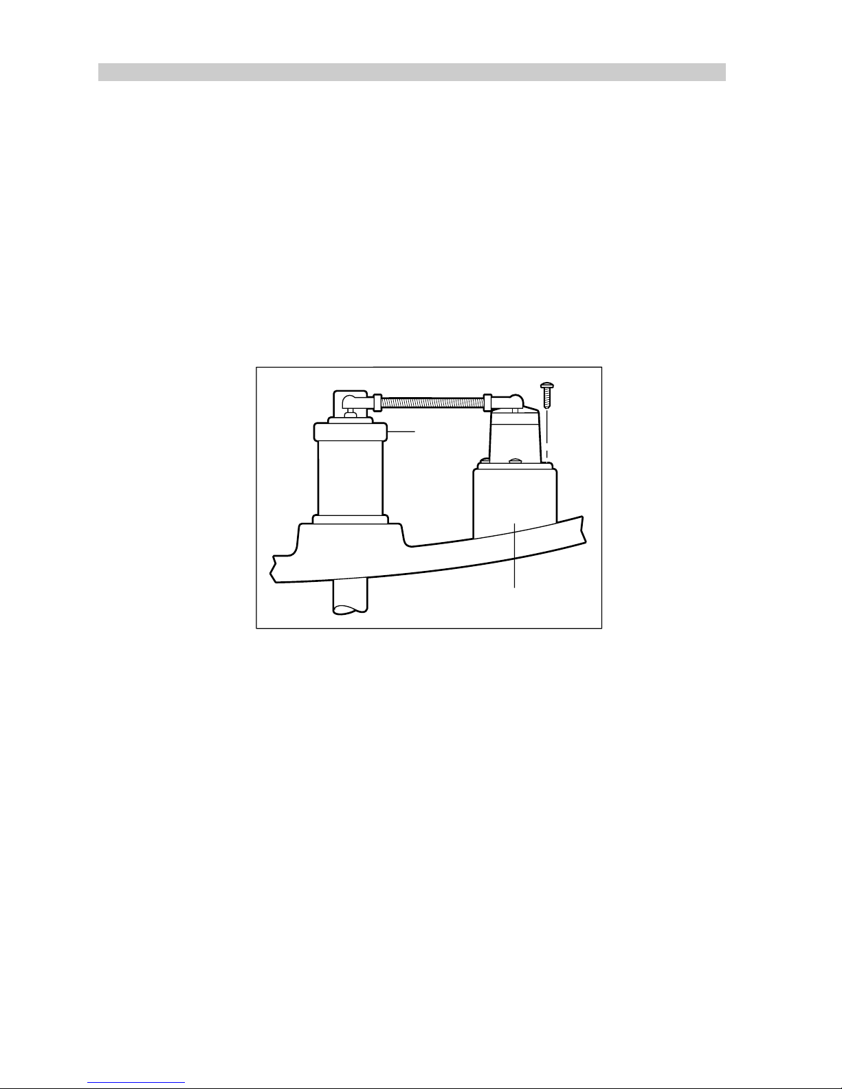
1. Using the self tapping screws provided, mount the rudder reference
transducer on a suitable base adjacent to the rudder stock.
X
Tiller arm
Mounting base
D195
2. Make sure that the base height of the rudder reference transducer
can maintain the correct vertical alignment between the rudder
reference transducer arm and tiller arm (as shown).
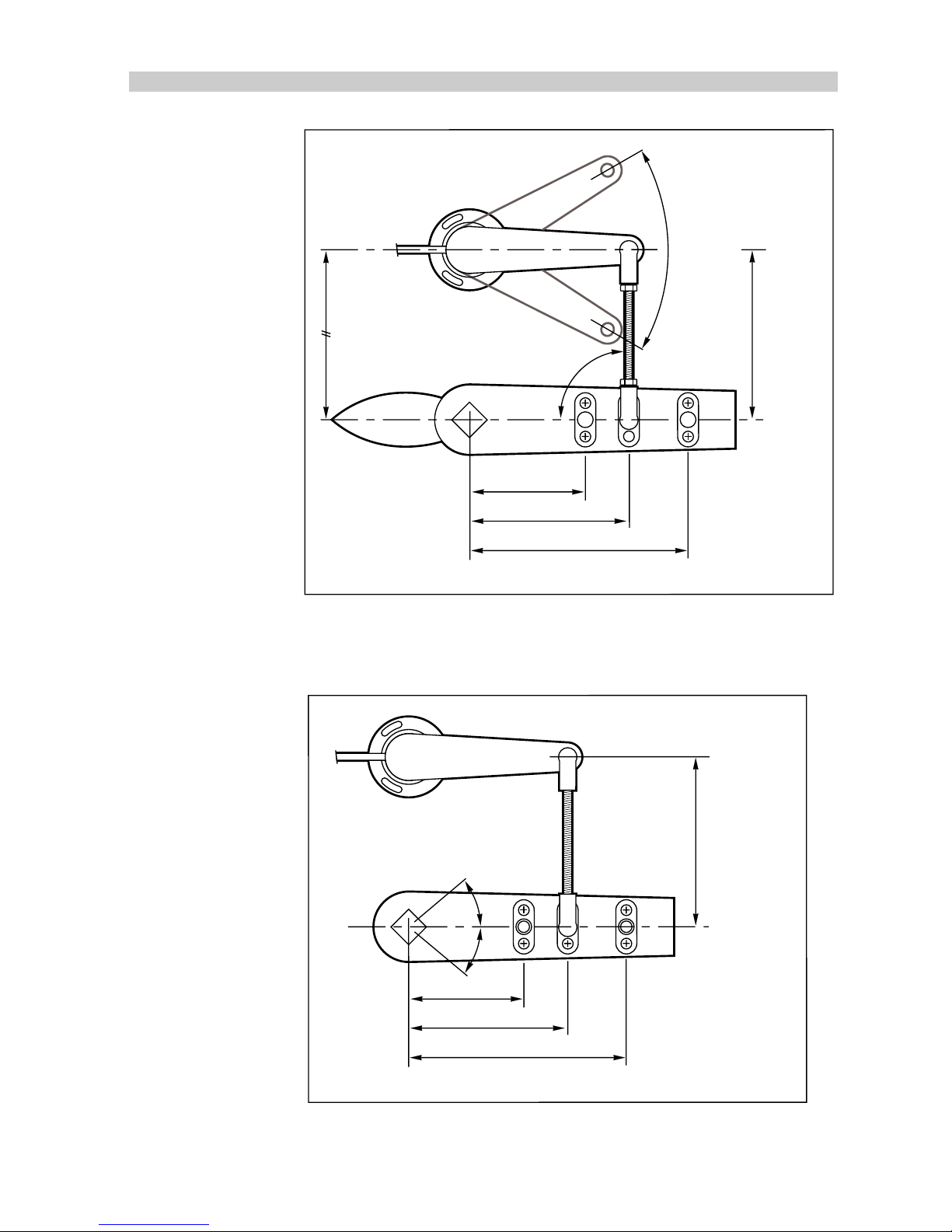
• To give the precise rudder position, the rudder reference transducer has
a built in spring to remove any free play in the linkage to the tiller .
• The rudder reference arm movement is limited to ± 60 degrees. Care
must be taken during installation to ensure that the rudder reference
arm is opposite the point of cable entry when the rudder is amidships.
Failure to do this could result in damage if the rudder reference arm is
driven onto its end stops by the steering system.
Page 32
Chapter 2: Installation
31
A
Parallel
Cable
entry
90°
Rudder amidships
± 60°
maximum
travel
permitted
D196/2
Min 101mm (4in)
'A' 140mm (5.5in)
Max 190mm (7.5in)
Min
75mm
(3in)
Max
310mm
(12.2in)
It is important to ensure that the dimensions (set out above) are within the
set limits and that the tiller and rudder reference arms are parallel to each
other.
A
D197
40°max
40°max
Min 101mm (4in)
'A' 140mm (5.5in)
Max 190mm (7.5in)
Min 75mm
(3in)
Max 310mm
(12.2in)
1. With the rudder amidships, the rudder reference arm should be
opposite the point of cable entry and at 90 degrees to the connecting
Page 33
32
TYPE 100/300 Operation and Installation Handbook
bar. Minor adjustments can be made by loosening the 3 securing
screws and rotating the transducer body.
2. The tiller pin must be positioned within the limits shown. Ideally,
dimension ‘A’ should be 140mm (5.5in). However, changes within the
given limits will not degrade the autopilot performance, but will slightly
alter the scaling of the rudder angle display on the control unit. The
tiller pin is secured to the tiller arm using the self tapping screws
provided.
3. Cut the threaded rod to length and screw on the lock nuts ‘Y’and the
ball pin sockets - the sockets can then be pressed onto the pins. Move
the rudder from side to side to ensure the linkage is free from any
obstruction at all rudder angles.
Cabling
1. Run the rudder reference cable back to the course computer.
2. Connect to the rudder reference terminals on the course computer.
GYRO 2 RUDDER REF. NMEA
+–+–
D894-1
Grey (screen) BlueRed Green
Note:
A 10m (30ft) extension cable is available for larger installations
(part no. D173).
Page 34
Chapter 2: Installation
33
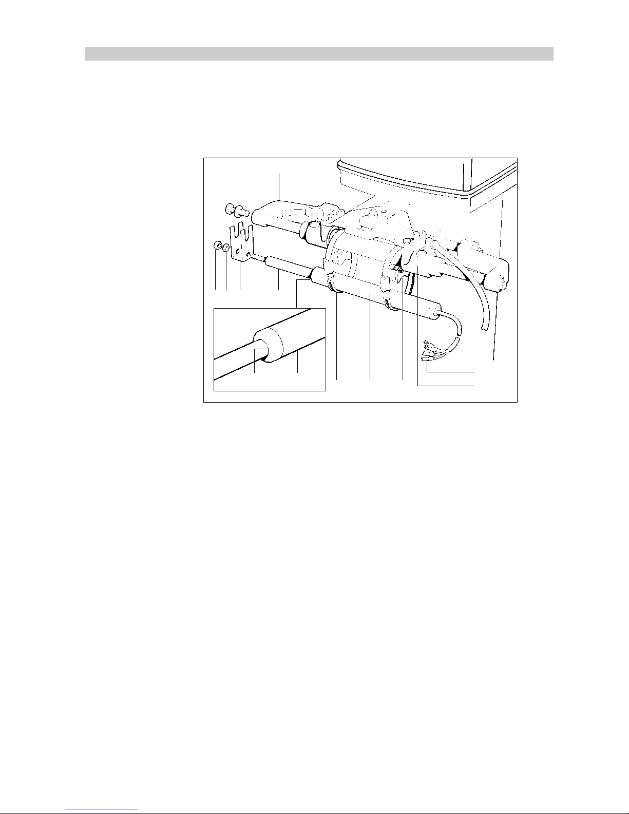
2.5 Linear Feedback Transducer
The Linear Feedback Transducer is designed for use with bullhorn type
outboard installations.
1110
2
78 3 9
564121
D717-1
Mounting
1. Operate the steering system so that the ‘bullhorn’ ram (1) is positioned
amidships.
2. Release the hydraulic pressure from the vessels hydraulic steering
system (if required). Refer to the manufacturer’s instructions for
correct procedures.
3. Loosen the starboard bolt that secures the ‘bullhorn’ ram (1) shaft to
the end bracket (2).
4. Assemble the U-bracket (3) over the end bracket (2) and the shaft of
the ‘bullhorn’ ram (1).
5. Hand tighten the starboard ‘bullhorn’ bolt to hold the U-bracket (3) in
position.
6. Fully open the hose clamps (6) using a flat bladed screwdriver.
7. Hang the hose clamps (6) over the ‘bullhorn’ ram (1).
8. Site the spacers (4) on the ‘bullhorn’ ram (1) and hold, temporarily,
with adhesive tape.
9. Pull the shaft (9) out of the linear feedback transducer (5) until the
alignment mark (10) is level with the end of the body (11).
Page 35

34
TYPE 100/300 Operation and Installation Handbook
10. Position the linear feedback transducer (5) on top of the spacers (4)
so that the threaded end of the shaft passes through the
U-bracket (3).
Note:
The linear feedback transducer should, under normal circum-
stances, be assembled with the shaft (9) pointing towards starboard.
However, if it is not possible to orientate the unit in this way, port installation is possible providing the red and green wires are reversed at the
course computer.
11. With the adjustment screw and barrel aligned with the spacers, close
the hose clamps (6) around the linear feedback transducer (5) and the
‘bullhorn’ ram (1).
12. Tighten the ‘bullhorn’ bolt to retain the U-bracket (3).
13. Fit and tighten the nut (7) and washer (8) to the shaft of the linear
feedback transducer (5).
Cabling
1. Run the linear feedback transducer cable back to the course
computer.
2. Connect to the course computer rudder reference terminals.
Note:
To allow for movement of the bullhorn, leave a loop of cable at the
end of the Linear Feedback Transducer.
GYRO 2 RUDDER REF. NM
+–
D895-1
TM
Grey (screen) BlueRed Green
Page 36

Chapter 2: Installation
35
2.6 Hydraulic Drive Systems
This section covers the installation of hydraulic system components
together with relevant plumbing and cabling procedures.
For optimum autopilot performance it is important that the pump specifications given below match the vessel's steering ram.
Pump to Cylinder Specifications
Pump Capacity
Type 1 80 to 230cc (4.9 to 14cu in)
Type 2 160 to 350cc (9.8 to 21cu in)
Type 3 250 to 460cc (15 to 28cu in)
CR1 350 to 500cc (21 to 30cu in)
CR2 500 to 1200cc (30 to 73cu in)
81004-04
Reversing Hydraulic Pumps (Type 1, Type 2 & Type 3)
Mounting
The hydraulic pump should be mounted in a horizontal position clear of
spray and possible water immersion. It should also be located as near as
possible to the hydraulic steering cylinder.
Bolt the hydraulic pump to a substantial member to avoid vibration that
could damage the interconnecting pipework.
Cabling
Using a suitably sized cable (see below) route the pump leads back to the
course computer and connect to the motor terminals.
Type 1 Drive Unit
Cable Length (Drive Unit
to Course Computer)
Cable Gauge Copper Area
Up to 3m (10ft) 12 AWG 2.5 mm
Up to 5m (16ft) 10 AWG 4 mm
Up to 7m (23ft) 8 AWG 6 mm
Up to 10m (32ft) 6 AWG 10 mm
Up to 16m (52ft) 4 AWG 16 mm
81004-05
Page 37

36
TYPE 100/300 Operation and Installation Handbook
Type 2 Drive Unit (12V)
Cable Length (Drive Unit
to Course Computer)
Cable Gauge Copper Area
Up to 5m (16ft) 8 AWG 6 mm
Up to 7m (23ft) 6 AWG 10 mm
Up to 16m (52ft) 4 AWG 16 mm
81004-06
Type 2 Drive Unit (24V)
Cable Length (Drive Unit
to Course Computer)
Cable Gauge Copper Area
Up to 3m (10ft) 12 AWG 2.5 mm
Up to 5m (16ft) 10 AWG 4 mm
Up to 7m (23ft) 8 AWG 6 mm
Up to 10m (32ft) 6 AWG 10 mm
Up to 16m (52ft) 4 AWG 16 mm
81004-05
Type 3 Drive Unit (12V)
Cable Length (Drive Unit
to Course Computer)
Cable Gauge Copper Area
Up to 5m (16ft) 8 AWG 6 mm
Up to 7m (23ft) 6 AWG 10 mm
Up to 16m (52ft) 4 AWG 16 mm
81004-06
Type 3 Drive Unit (24V)
Cable Length
(Distribution Panel to
Pump)
Cable Gauge Copper Area
Up to 3m (10ft) 8 AWG 6 mm
Up to 7m (22ft) 6 AWG 10 mm
Up to 16m (52ft) 4 AWG 16 mm
81004-07
Page 38
Chapter 2: Installation
37
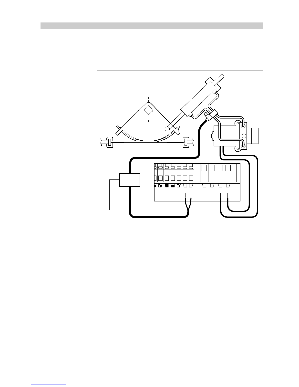
Note:
The reversing hydraulic pumps do not require a clutch connection.
If the pump is to be used to drive a secondary steering ram, a bypass
valve will have to be fitted as shown in the following illustration.
D915-1
Talk SeaTalk CLUTCH MOTORPOWER
+–+ –
12
Power
Relay
Note:
A 5 amp relay should be used to energise the bypass valve. The
relay should have a 12V coil (taking less than 500ma) and be driven by the
clutch output on the course computer connector.
Plumbing
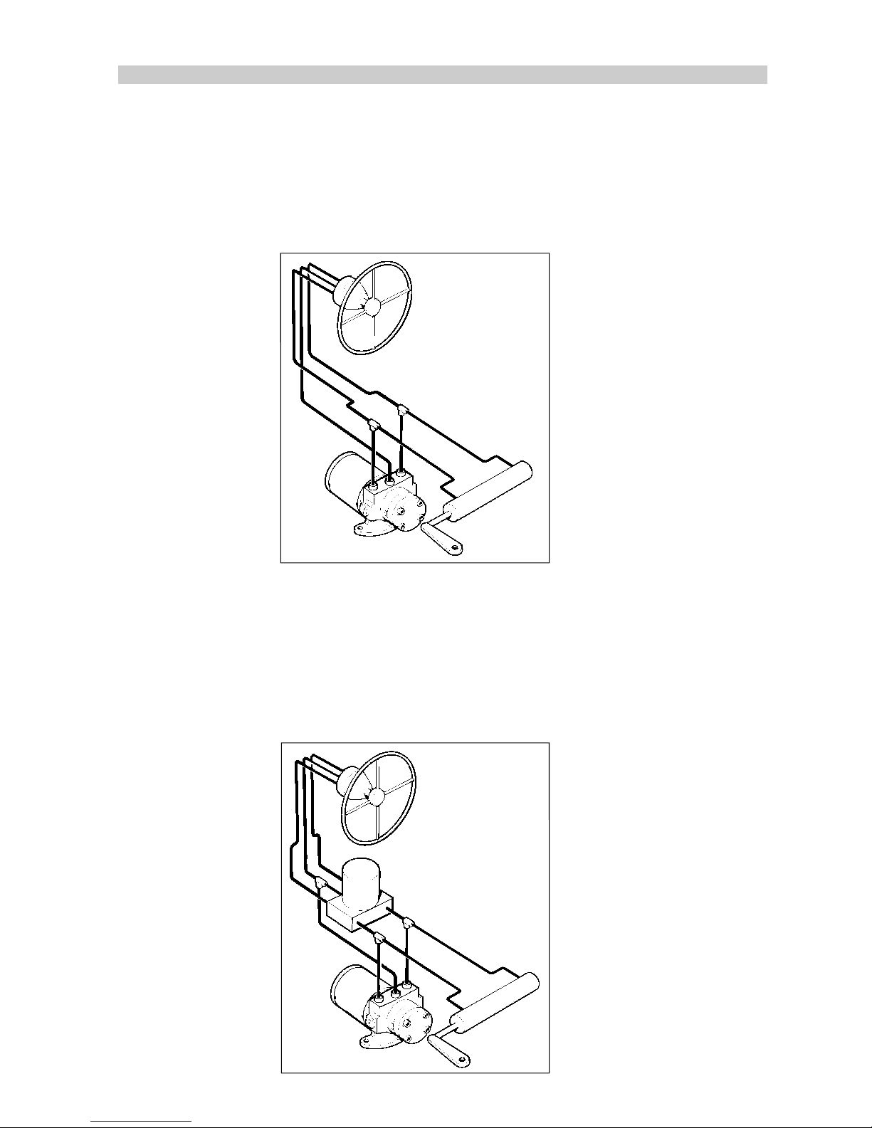
There are three basic types of hydraulic steering systems:
• two line system
• three line system
• two line pressurised system
Typical connection points for the autopilot pump are shown for each type.
In all cases it is strongly recommended that the steering gear
manufacturer is consulted.
All hoses used to fit the pump should match or exceed the specification of
those used in the existing steering system.
Page 39
38
TYPE 100/300 Operation and Installation Handbook
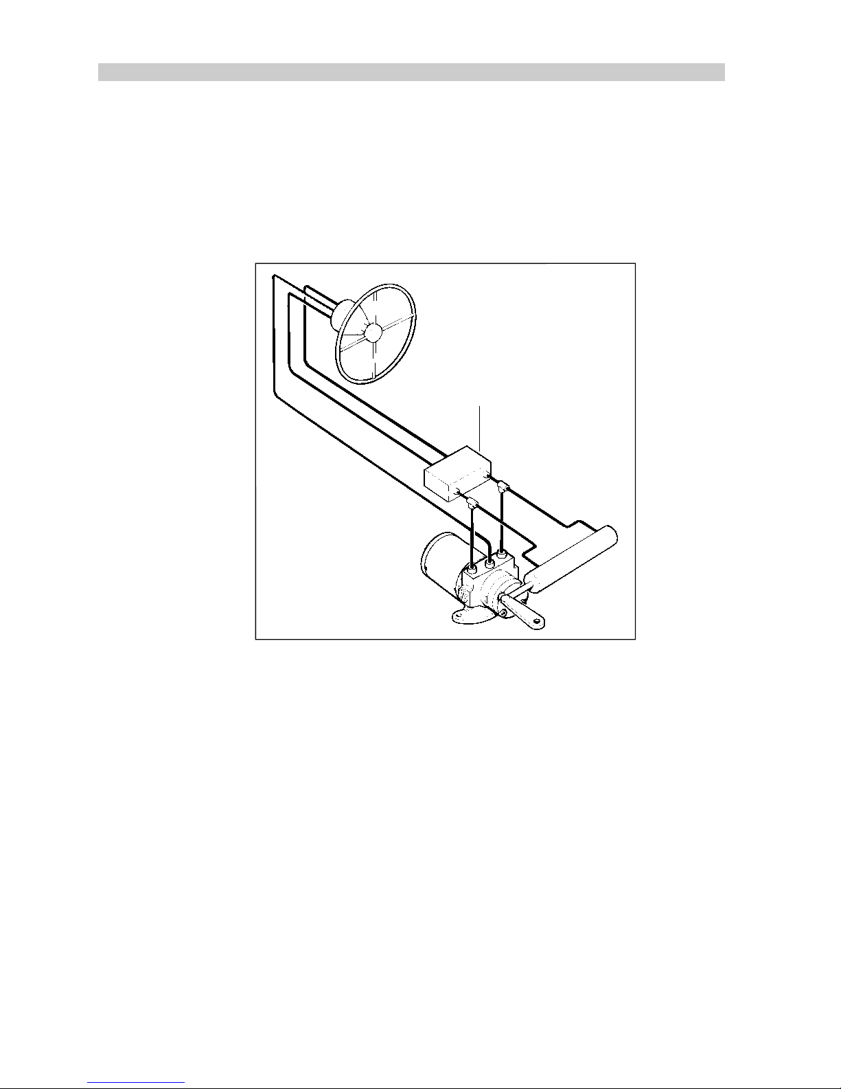
It is also necessary to ensure that the helm pump is fitted with reversing
check valves, otherwise the autopilot pump will drive the helm pump
(sometimes referred to as motoring the wheel) in preference to moving the
ram. Single helm pump systems without check valves should incorporate
a double pilot check valve and block (available as part Z068). This is shown
in the following illustration.
Check valve (Z068)
D274-3
Notes:
1. A double pilot check valve may also be necessary on long tubing runs.
Tubing expansion may result in poor autopilot performance. The valve
should be installed close to the cylinder with the pump in between (as
shown).
2. If the vessel has two steering positions, check valves will already be
fitted to ensure independent operation of the two wheels.
Minimisation of hydraulic fluid loss during connection of the drive unit will
help to reduce the time and effort required later to bleed the system of
trapped air. Absolute cleanliness is essential since even the smallest
particle of foreign matter could interfere with the correct function of the
steering system precision check valves.
Page 40
Chapter 2: Installation
39
Two line system
A typical two line steering system is shown in the following illustration.
Hydraulic fluid can be pumped into the ram in either direction depending
on the direction of the helm pump rotation. The autopilot pump is connected to the system as shown.
D271-2
Two line pressurised system
Two line pressurised systems have an external pressurised reservoir. This
reduces the possibility of inducing air into the system and any sponginess
felt due to pipe expansion. The autopilot pump is connected to the system
as shown in the following illustration.
Note:
Refer to the manufacturer’ s instructions on depressurising the system.
D272-2
Page 41

40
TYPE 100/300 Operation and Installation Handbook
Three line system
In a three line system, hydraulic fluid flows in one direction only - out of the
helm pump to the ram and then returning from the other side of the ram to
the reservoir via a common return line.
A uniflow valve block will be fitted in the system to ensure that all returned
fluid from the ram is directed back to the reservoir.
D273-2
Bleeding the system
Correct bleeding of the hydraulic system is one of the most important
steps when installing a hydraulic pump. The presence of air in the hydraulic
system will not only reduce performance of the autopilot but also the
overall operation of the steering system.
Further to the manufacturer’s instructions for bleeding the steering
system, the following procedures should be carried out to bleed the
autopilot pump.
1. Press and hold the -10 degree key : the autopilot pump will try to drive
the rudder to port.
2. Counter this rudder movement by turning the helm to starboard to
keep the rudder stationary. This will cause any air in the pump to rise
to the helm pump and exhaust into the reservoir.
Page 42
Chapter 2: Installation
41
3. Reverse this action to clear any air on the other side of the pump as
follows:
4. Press and hold the +10 degree key: the autopilot will try to drive the
rudder to starboard.
5. Counter the rudder movement by turning the helm to port.
Note:
Monitor the reservoir tank at all times during the bleeding proce-
dure, make sure it remains full of the hydraulic fluid recommended by the
manufacturer. If air is left in the system the steering will feel spongy,
particularly when the wheel is turned to the hardover position.
Constant Running Hydraulic Pump
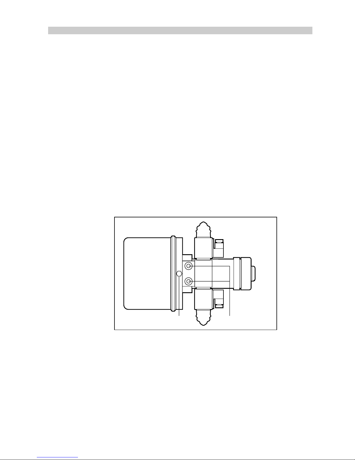
Mounting
Bolt the constant running hydraulic pump to a suitable horizontal surface.
The service ports are tapped to 1/4in B.S.P. and the reservoir port is
tapped to 3/8in. B.S.P. Three N.P.T. adaptors are included for conversion
to N.P.T. where required.
Reservoir port (3/8in B.S.P.) Service port (1/4in B.S.P.)
D765-1
Page 43
42
TYPE 100/300 Operation and Installation Handbook
Cabling
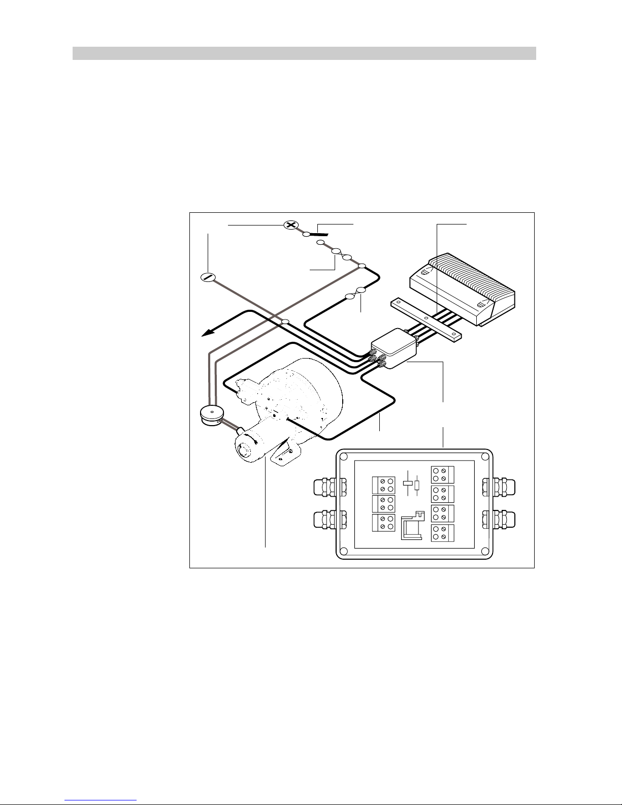
The constant running interface must be used on all installations with
constant running hydraulic pumps. The main power supply is led to the
interface and then onto the course computer. The interface unit has
connections for the solenoid valves and the bypass valve, if one is
required. The pump should be wired (as shown) using the specified cable
size and designated circuit breaker.
Supply
Main breaker
Type CR
interface unit
To bypass
valve
Clutch drive
25A
Solenoid 'A' cable
Power pack motor supply
3L (12V) – 50A
4.5L (12V) – 70A
3L (24V) – 30A
4.5L (24V) – 40A
RLY1
D2
D1
+ – + – + –
+ –
+ –
+ –
BYPASS
VALVE
BATTERY
A B
SOLENOIDS
M1 M2
SUPPLY
CLUTCH
D778-1
Page 44

Chapter 2: Installation
43
Pump Cable
Cable Length
(Distribution Panel to
Pump)
Cable Gauge Copper Area
Up to 3m (10ft) 8 AWG 6 mm
Up to 7m (22ft) 6 AWG 10 mm
Up to 16m (52ft) 4 AWG 16 mm
81004-07
Solenoid Cable
Solenoid Cable Length
(Course Computer to Pump)
Cable Gauge Copper Area
Up to 7m (23ft) 12 AWG 2.5 mm
Up to 12m (39ft) 10 AWG 4.0 mm
Up to 17m (55ft) 8 AWG 6.0 mm
81004-08
An isolator switch should be installed in the power supply to the complete
system.
The solenoid valve connectors can only accept cable up to 12 AWG. If
larger cable is required, 18 inches of 12 AWG should be used to wire to
the connectors.
The Type CR Interface may also be connected to alternative constant
running hydraulic pump providing:
• the solenoid coils take less than 10 amps
• the response time of the solenoid valve is less than 80 milliseconds
• the operating voltage of the solenoid coils is the same as the course
computer supply voltage.
It is important to minimise the overall cable length between the pump and
the vessels power distribution panel.
Page 45
44
TYPE 100/300 Operation and Installation Handbook
Plumbing
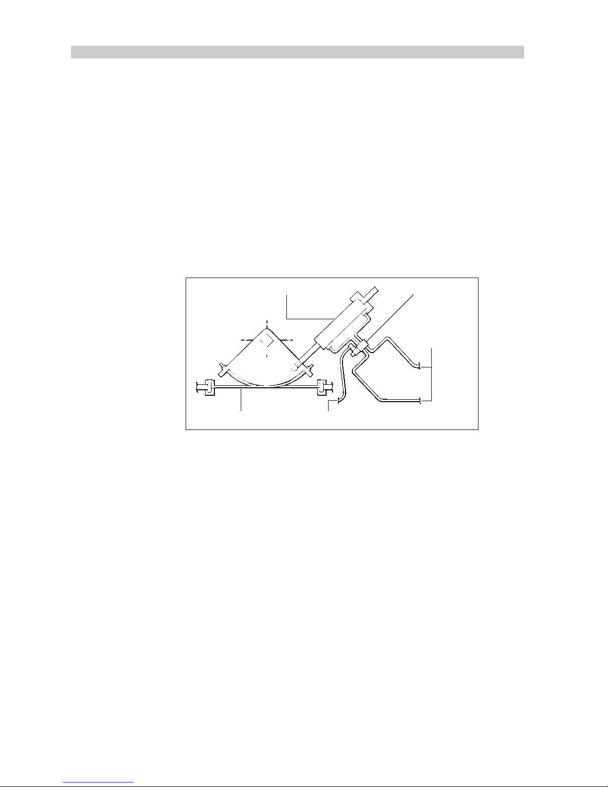
If the autopilot operated hydraulic cylinder is independent of the manual
steering system, a solenoid operated bypass valve
(Z079 (12V),Z122 (24V)) should be fitted to allow the cylinder to backdrive
when manual steering. The bypass valve should be connected to the
‘bypass’ connector on the Type CR Interface Unit.
The bypass valve should be mounted between the autopilot steering
cylinder ports and, under normal circumstances, be de-energised to allow
the cylinder to backdrive. When the autopilot is engaged, the valve is
energised by the Type CR Interface to allow the autopilot steering cylinder
to drive the rudder.
Hydraulic cylinder
Bypass valve
Autopilot
hydraulic
drive
Manual steering system Cable to course computer 'Bypass' connector
D766-1
Note:
The bypass valve voltage must be matched to the course computer
supply voltage, i.e. 12V or 24V.
If the steering cylinder is unbalanced (single ended), a pilot operated
pressure relief valve must be connected (as shown) to enable excess oil to
be returned to the reservoir when the cylinder ram is retracting.
Page 46
Chapter 2: Installation
45
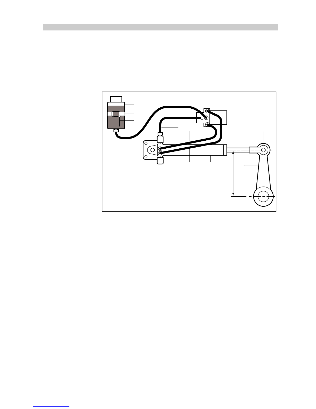
Hydraulic Linear Actuator
The hydraulic linear actuator, with built in solenoid operated bypass valve
and load limiting system, is designed for use as a secondary autopilot
steering cylinder. The system is supplied prefilled and preplumbed for
ease of installation.
1
4
5
62
9
7
83
10
11
D776-1
Drive Dimension X
Type 2 180mm (7.1in)
Type 3 267mm (10.5in)
X
1 Reservoir 2 Pump 3 Cylinder 4 Tie-wrap 5 Clip 6 Reservoir hose 7 Pump hose A
8 Pump hose B 9 Cylinder hose 10 Cylinder ball joint 11 Quadrant
Installation
Caution:
It is important to note that the hydraulic linear actuator can exert a
thrust of upto 2700 Ibs - this is the equivalent weight of a large
family saloon car. If there is any doubt about the strength of the
existing tiller arm or quadrant the steering gear manufacturer
must be consulted. Also, the mounting foot should be bolted to a
substantial member and always over engineer to ensure reliability
and maintenance of correct alignment.
Page 47
46
TYPE 100/300 Operation and Installation Handbook
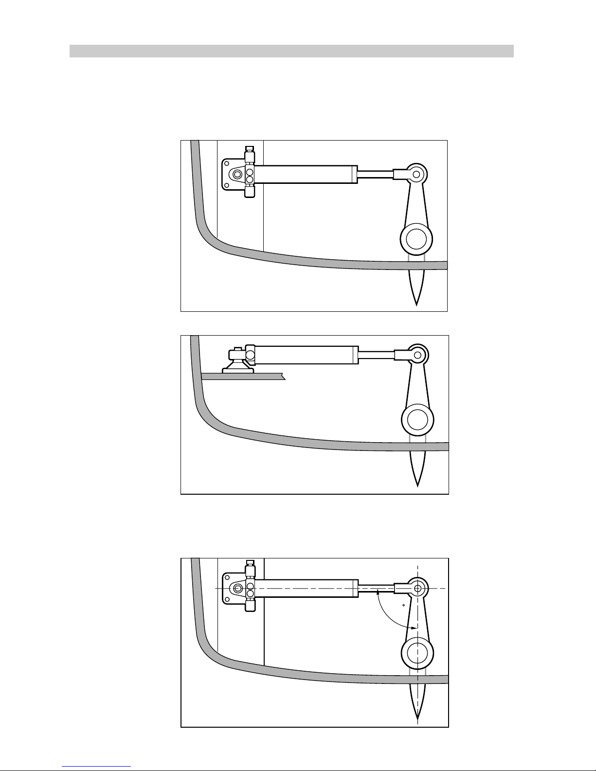
When siting the actuator the following points should be noted:
1. The actuator mounting foot must be mounted to a horizontal surface.
There is insufficient movement in the swivel joint for vertical mounting.
D1034-1
✓
View from above
✗
D1035-1
View from above
2. The drive end must be at right angles to the hydraulic cylinder when
the tiller is amidships.
D1037-1
90
View from above
Page 48
Chapter 2: Installation
47
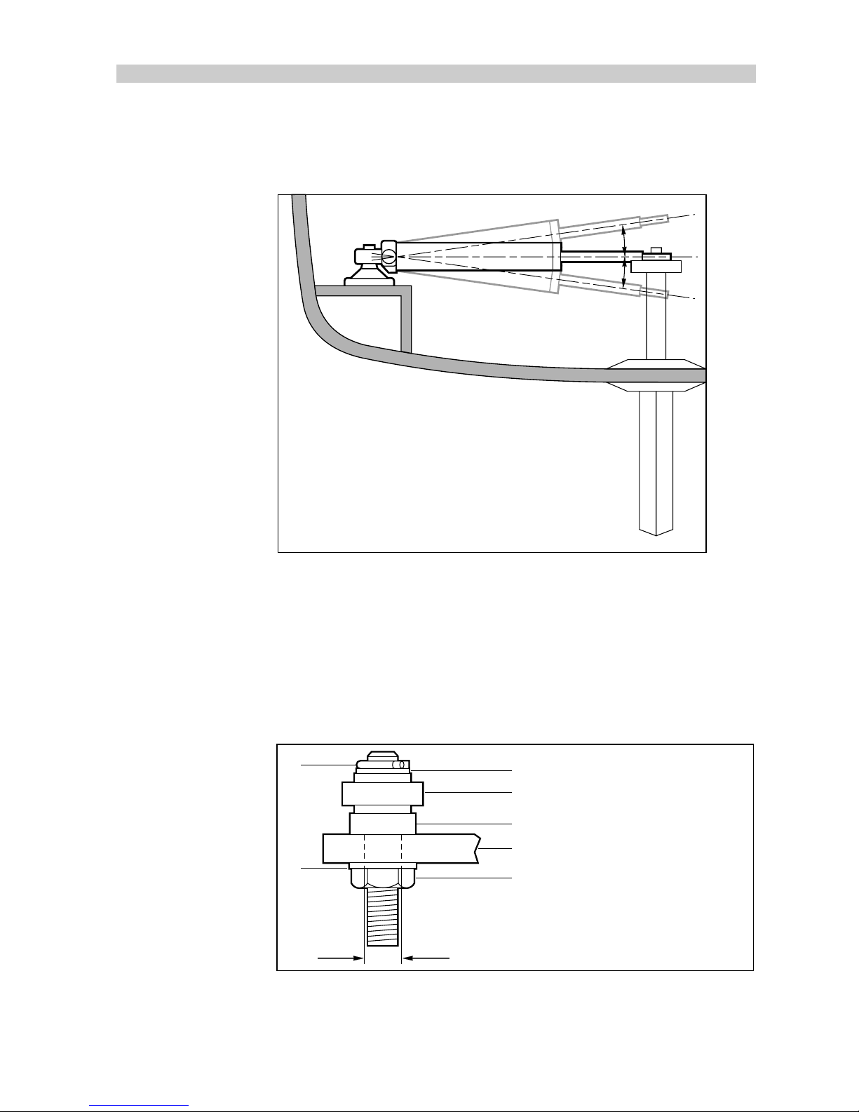
3. Accurate angular alignment between the hydraulic cylinder and the
tiller arm plane of rotation is extremely important – under no
circumstances should any misalignment exceed +/- 5 degrees.
D1036-1
5° Max.
5° Max.
View from astern
Caution: The push rod must not be shortened as it contains hydraulic fluid.
4. The push rod ball end must be attached to the tiller arm at the radius
specified on page 45. Use the supplied fixing bolt with its flange
positioned between the ball end and the tiller arm. It is very important
that this bolt is a tight fit in the tiller arm. Use Loctite 638 (or an
equivalent) to secure the tiller bar bolt and lock the securing nut.
X
A
B
C
D
F
D1046-1
E
G
Hole size X:
Type 2, 11.96 - 12.06mm
(0.471 - 0.475in)
Type 3, 19.9 - 20mm
(0.783 - 0.787in)
A Spring clip B Washer
C Washer D Push rod ball end
E Fixing bolt flange F Tiller arm
G Fixing nut
5. Position the reservoir (1) so that it is at least 150mm (6in.) above the
pump (2). The pump (2) should be sited above the cylinder (3).
6. Use the cable tie-wrap (4) to secure the reservoir (1) to the clip (5).
Page 49
48
TYPE 100/300 Operation and Installation Handbook
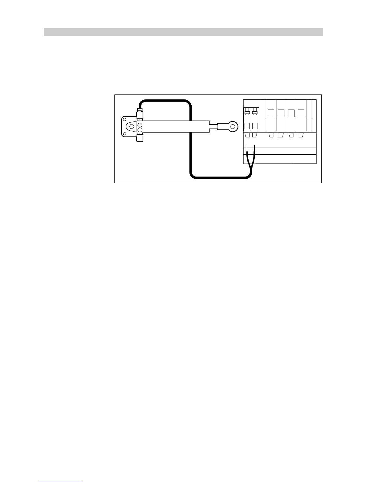
Cabling
1. Run the pump and bypass valve cable back to the course computer.
2. Wire to the course computer clutch and motor connections.
CLUTCH MOTORPOWER
+–+ –
12
D917-1
Final Preparations Before use
1. Remove the reservoir cap and replace with the supplied standard cap.
2. Set the reservoir valve to the open position.
Caution:
Make sure the mechanical limits of the steering system stop
rudder movement before the cylinder reaches its end stops failure to do this will damage the steering cylinder and will invalidate the warranty.
3. Switch the Autopilot to ‘Auto’ mode and, using the 10 degree course
change keys, steer hard-over to hard-over to check for correct
operation and any possible leaks.
4. Set-up the autopilot end stops as described in the autopilot installation
handbook.
WARNING:
KEEP CLEAR OF MOVING STEERING LINKAGES AT ALL TIMES.
Page 50
Chapter 2: Installation
49
2.8 Mechanical Drive Systems
Rotary Drive Unit
The rotary drive is coupled to the steering by a chain drive. Most steering
gear manufacturer's supply special autopilot drive attachments (many
include this as standard). The Edson Company is a good source.
Mounting
Having selected the position for attachment of the autopilot drive chain, it
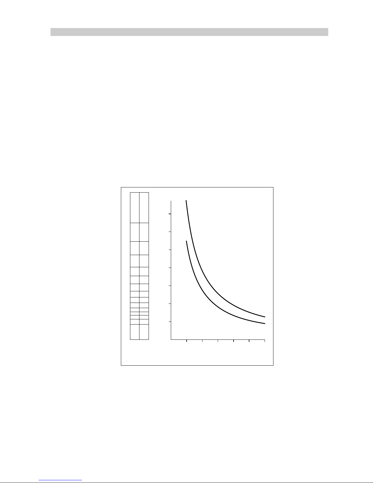
is necessary to determine the chain reduction ratio.
Count the number of turns of the steering gear shaft (driven sprocket)
when the rudder is driven from hardover to hardover. Determine the
sprocket sizes required from the following table.
17
19
25
15
13
17
15
13
17
15
13
15
17
Driven Sprocket
Driver Sprocket
76
76
57
57
57
38
38
38
25
25
25
25
25
1
23456
1
2
3
4
5
6
7
Number of Driven Sprocket
Turns Hardover Hardover
Chain Reduction Ratio
Rotary Drive Chain Reduction Ratios
Type 1
Type 2
D757-1
These ratios provide good steering performance for most vessels. If the
vessel is thought to have unusual steering characteristics, contact our
Product Support Department, or an authorised representative, for advice.
A standard 3/8in. or 1/2in. pitch chain is recommended for the chain drive
and, ideally, the drive sprocket should not have less than 15 teeth. Bore
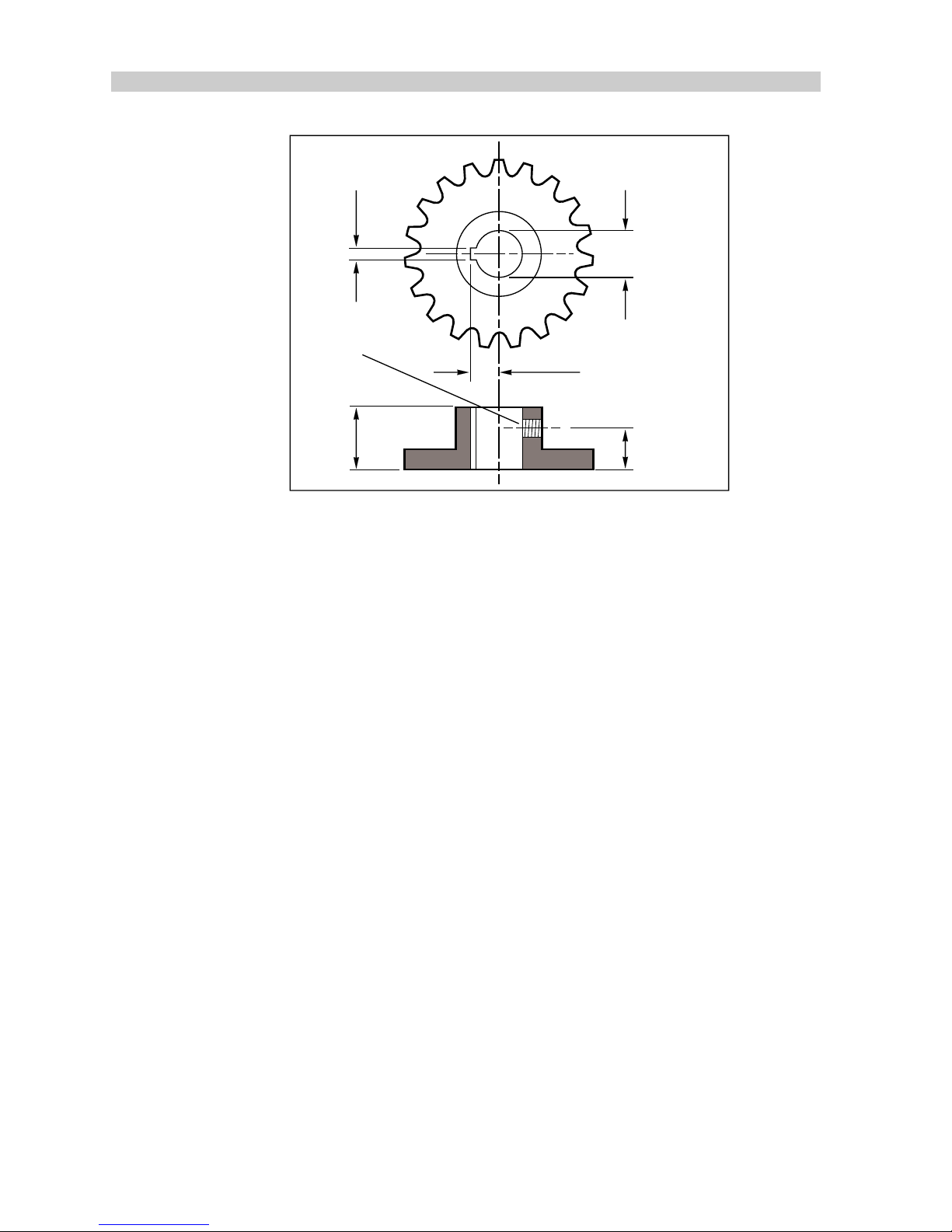
and keyway dimensions for the drive unit sprocket are detailed in the
following illustration. It is essential that these bore and keyway dimensions
are strictly adhered to. All sprockets must be keyed, set screwed to their
shaft and finally secured with loctite.
Page 51
50
TYPE 100/300 Operation and Installation Handbook
9.46mm – 9.61mm
(0.3725in – 0.3785in)
3.22mm – 3.24mm
(0.127in – 0.1275in)
15.89mm – 15.9mm
(0.6256in – 0.6275in)
19mm
(0.75in)
12.7mm
(0.5in)
Grub screw
D758-1
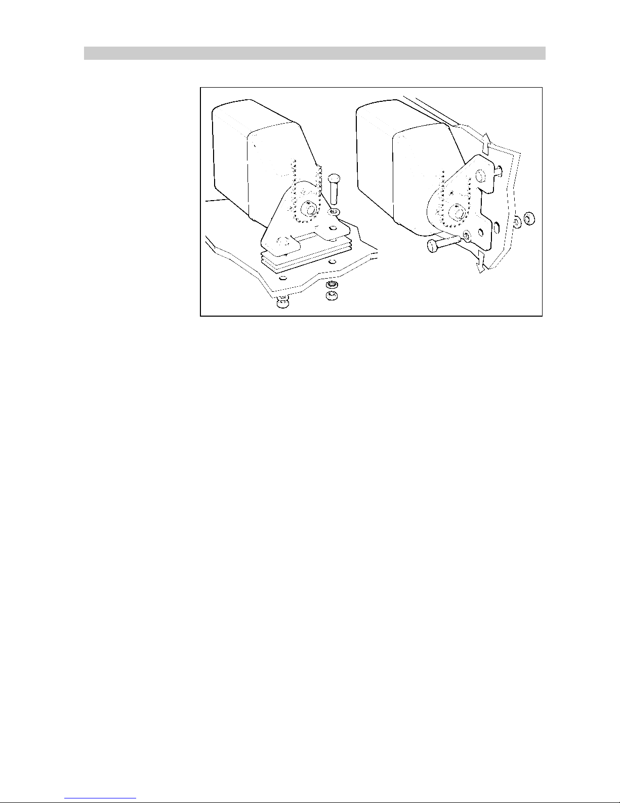
The drive unit must be bolted to a substantial frame member. The
mounting foot is secured to the drive unit by four equally spaced allenhead
screws and it may be rotated through 90 degrees to provide a more
convenient mounting position, if required. In some cases it may be
necessary to fabricate a special frame to mount the drive unit.
It should be noted that chain tension can exceed 500 lb (230Kg) and,
therefore, an extremely rigid mounting structure is vital to maintain good
chain alignment. Installation failures can occur in this area and overengineering is strongly recommended for drive unit mounting. All
fastenings should be secured with lock washers.
Provisions must also be made for chain adjustment. This is achieved by
removable shims placed under the mounting foot or, alternatively, by
elongated clearance holes in the mounting frame.
Page 52
Chapter 2: Installation
51
D759-1
Both sprockets must be accurately aligned to run in the same plane.
Correct alignment must be carefully checked by means of a straight edge.
The gearbox can be mounted in any position. Additionally, the drive
sprocket may face in any direction as the steering sense can, by reversing
the polarity of the drive motor connection, be corrected when installation is
complete.
Finally, the chain should be tensioned until it is just tight and there is
minimal lost motion to the drive system. Total lost motion between the
driven sprocket attached to the steering system and the rudder stock
should not, under any circumstances, exceed 2% of the total movement.
If lost motion exceeds this level it must be corrected, otherwise steering
performance will be impaired.
Having completed installation of the drive unit, turn the steering wheel from
hardover to hardover and check that the chain and sprockets driving the
actuator move freely and are in alignment.
Page 53

52
TYPE 100/300 Operation and Installation Handbook
Cabling
The rotary actuator has electrical connections for both the drive motor
(red/black cores) and clutch (twin cable with blue/red cores). Using a
suitable size cable (see tables), route back to the course computer and
connect to the clutch and motor terminals.
D902-1
SeaTalk CLUTCH MOTORPOWER
+–+ –
12
Type 1 Drive Unit
Cable Length (Drive Unit
to Course Computer)
Cable Gauge Copper Area
Up to 3m (10ft) 12 AWG 2.5 mm
Up to 5m (16ft) 10 AWG 4 mm
Up to 7m (23ft) 8 AWG 6 mm
Up to 10m (32ft) 6 AWG 10 mm
Up to 16m (52ft) 4 AWG 16 mm
81004-05
Type 2 Drive Unit (12V)
Cable Length (Drive Unit
to Course Computer)
Cable Gauge Copper Area
Up to 5m (16ft) 8 AWG 6 mm
Up to 7m (23ft) 6 AWG 10 mm
Up to 16m (52ft) 4 AWG 16 mm
81004-06
Page 54
Chapter 2: Installation
53
Type 2 Drive Unit (24V)
Cable Length (Drive Unit
to Course Computer)
Cable Gauge Copper Area
Up to 3m (10ft) 12 AWG 2.5 mm
Up to 5m (16ft) 10 AWG 4 mm
Up to 7m (23ft) 8 AWG 6 mm
Up to 10m (32ft) 6 AWG 10 mm
Up to 16m (52ft) 4 AWG 16 mm
81004-05
Linear Drive Unit
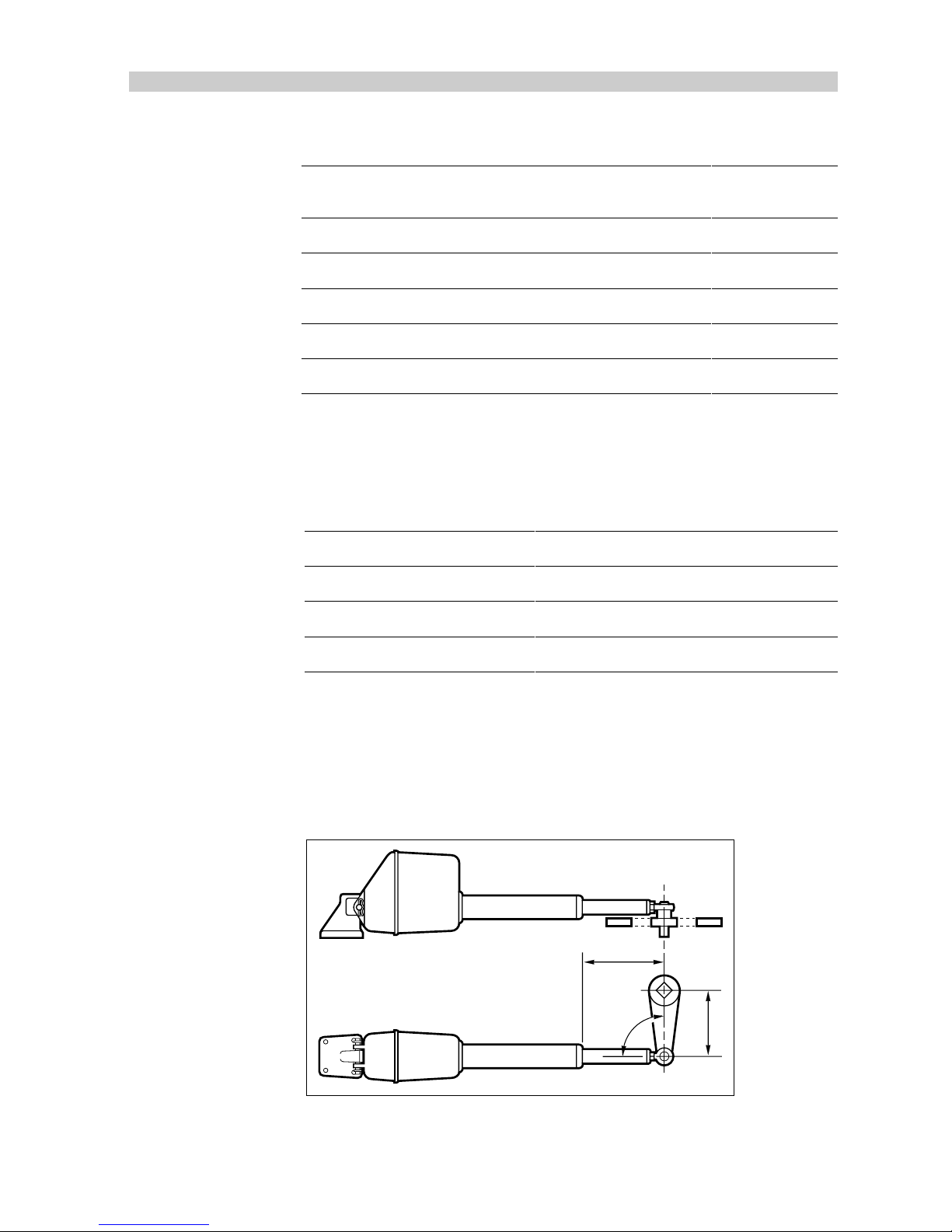
The linear drive unit connects directly on to the rudder stock at the tiller
arm radius (shown below).
Drive Unit Tiller Radius (B)
Type 1 250mm (10in)
Type 2S 250mm (10in)
Type 2L 360mm (14in)
81004-09
It is preferable to couple the linear drive unit to the rudder stock via an
independent tiller arm (Edson and Whitlock offer a standard fitting). In
certain cases, however, it may be possible to couple the pushrod to the
same tiller arm, or rudder quadrant employed, by the main steering
linkage.
Mid Stroke
'B'
90°
D760-1
Caution: The linear drive system can exert a thrust of over 1000Ib.
(450Kg). The steering gear manufacturer must be consulted if any doubt
exists about the strength of the existing tiller arm or rudder quadrant.
Page 55
54
TYPE 100/300 Operation and Installation Handbook
Mounting
When siting the linear drive unit, the following points should be noted:
• The drive unit mounting bracket can be attached to any horizontal or
vertical surface. Also, the drive unit can be mounted upside down if
required.
• The ball end fitting will allow up to 5 degrees misalignment between the
pushrod and tiller arm plane of rotation. Accurate angular alignment is
extremely important and, therefore, under no circumstances should this
limit be exceeded.
• The drive unit must be at right angles to the tiller arm when the rudder is
amidships.
• The drive is clear of any bilge water.
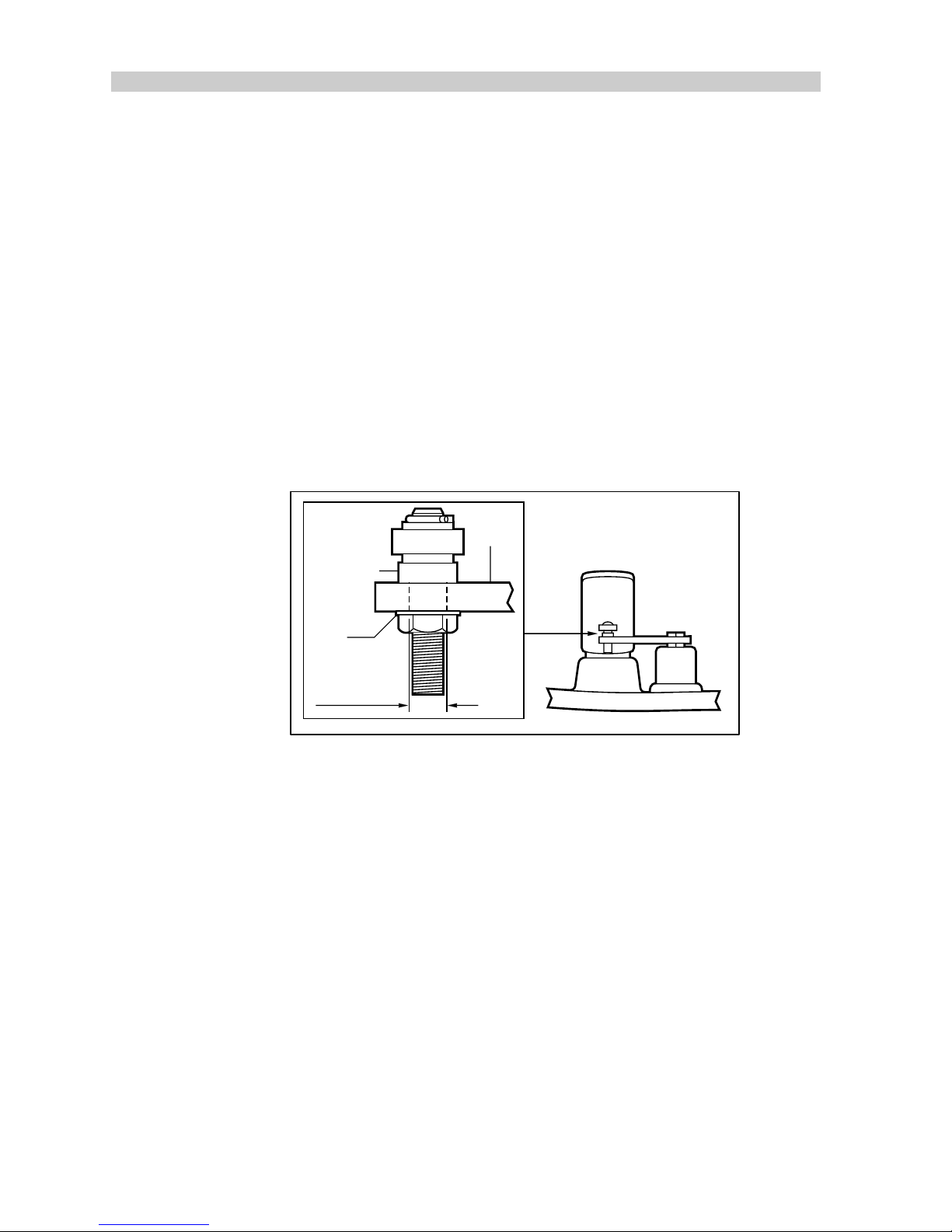
Lock
washer
Tiller
arm
Fixing
bolt flange
Hole dia.
0.52in (13mm)
D761-1
• The mounting bracket should be bolted to a substantial frame member.
Always over-engineer to ensure reliability and maintenance of
correct alignment.
The pushrod ball end must be attached to the tiller arm, using the adaptor
pin (supplied), with its flange positioned between the ball end and the tiller
arm. It is vitally important that the lock washer (supplied) is used and that
the nut is tightened fully.
The mounting bracket should be attached with four stainless steel 3/8in.
bolts and locknuts/lock washers.
Having installed the drive unit, turn the steering wheel from hardover to
hardover and check that:
• no part of the drive unit fouls the vessels structure.
• the mechanical limit stop on the vessels steering system is reached
before the actuator reaches its mechanical limit.
• angular movement of the ball end fitting is less that 5 degrees.
Page 56
Chapter 2: Installation
55
Cabling
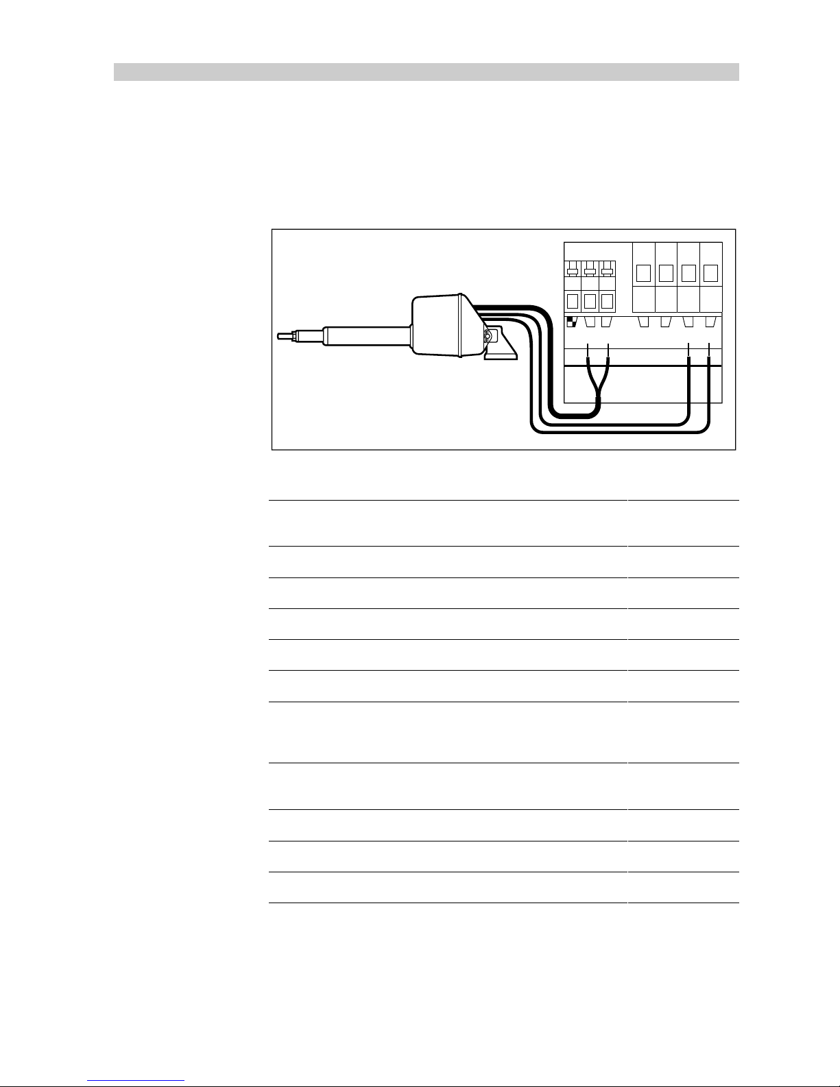
The linear drive unit has electrical connections for both the drive motor and
clutch. Using a suitable size cable (see tables), route back to the course
computer and connect to the clutch and motor terminals as shown.
D902a-1
lk CLUTCH MOTORPOWER
+–+ –
12
Type 1 Drive Unit
Cable Length (Drive Unit
to Course Computer)
Cable Gauge Copper Area
Up to 3m (10ft) 12 AWG 2.5 mm
Up to 5m (16ft) 10 AWG 4 mm
Up to 7m (23ft) 8 AWG 6 mm
Up to 10m (32ft) 6 AWG 10 mm
Up to 16m (52ft) 4 AWG 16 mm
81004-05
Type 2 Drive Unit (12V)
Cable Length (Drive Unit
to Course Computer)
Cable Gauge Copper Area
Up to 5m (16ft) 8 AWG 6 mm
Up to 7m (23ft) 6 AWG 10 mm
Up to 16m (52ft) 4 AWG 16 mm
81004-06
Page 57
56
TYPE 100/300 Operation and Installation Handbook
Type 2 Drive Unit (24V)
Cable Length (Drive Unit
to Course Computer)
Cable Gauge Copper Area
Up to 3m (10ft) 12 AWG 2.5 mm
Up to 5m (16ft) 10 AWG 4 mm
Up to 7m (23ft) 8 AWG 6 mm
Up to 10m (32ft) 6 AWG 10 mm
Up to 16m (52ft) 4 AWG 16 mm
81004-05
Stern drive Actuator
The stern drive actuator can be fitted to power assisted Stern drive
systems made by Volvo-Penta, Mercruiser, OMC and Yamaha. Different
installation kits are available to cover most of these installations.
Note:
Older Volvo steering systems (Pre type 872215) require an adaptor
bracket (D129).
Mounting
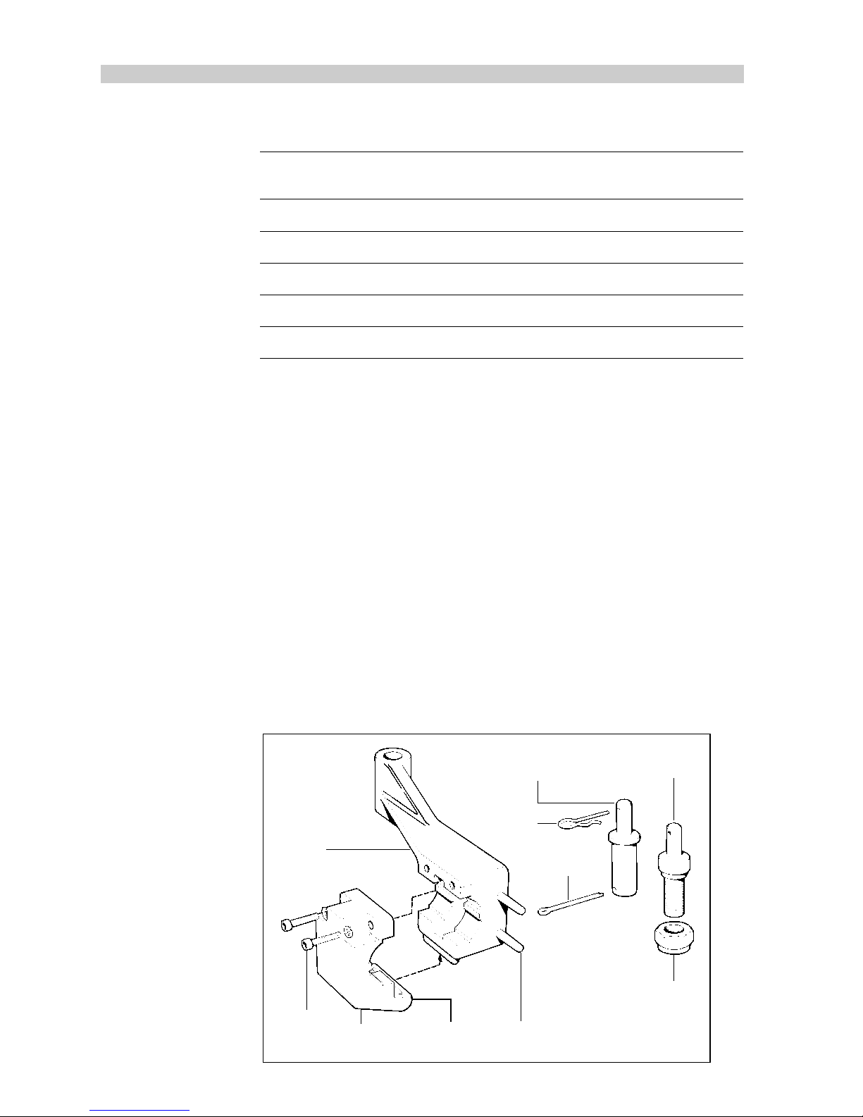
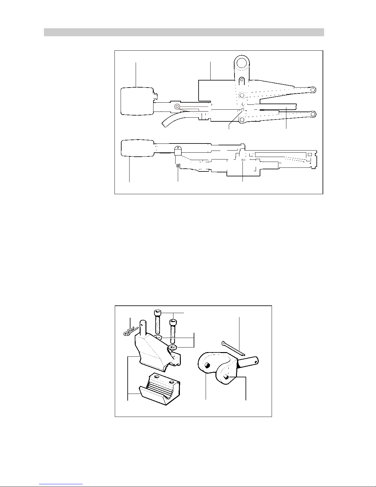
Volvo (Pre type 872215)
Fitting to this type of engine requires an adaptor bracket (M81139).
The stern drive actuator should be connected to the centre hole on the
tiller arm. On twin engine installations, this is the position used to connect
the engine tie bar to link the two tiller arms.
Hexagonal
key bolt
(2 off)
Spring
washer (2 off)
Bracket
clamp
Mounting
bracket
Location
pin
Nyloc nut
Split pin
Small
spring
clip
Adaptor pin
(Multi-engine mount)
Adaptor pin
(Single engine mount)
D768-1
Page 58
Chapter 2: Installation
57
1. Push the mounting bracket behind the steering cable, sliding the
location pins either side (top and bottom) of the Volvo power steering
block.
2. The bracket clamp hinges onto the mounting bracket and is located
using the two allenhead key bolts. Tighten the two bolts evenly until
the bracket is securely located.
Bracket Large diameter
Valve block
Spool valve shoulder
Cable
clamp nut
D769-1
D129 Mounting bracket
D129 Mounting bracket
Location pin
Steering
cable
Bracket clamp
Volvo Penta
steering valve block
Steering cable
Cable clamp nut
Valve shoulder to
remain out of bracket
3. Uncouple the engine tie bar from the outdrive tiller arm by bending
back the locking tabs and removing the cotter pin. This should be
replaced with the multi-engine adaptor pin. Make sure that it is
secured properly with a split pin (on single engine installations, fit the
single engine adaptor pin in the vacant middle hole in the tiller arm).
Page 59
58
TYPE 100/300 Operation and Installation Handbook
Drive unit
Drive unit
Valve block
Engine tie bar
Small spring clip
Split pin Split pin
D770-1
4. Attach the drive unit to the mounting bracket as shown above and
secure split pin provided. The small spring clip can then be used to
attach the drive unit to the adaptor pin.
5. Slowly turn the steering system from hardover to hardover. It is most
important that the drive unit and the adaptor pin bracket do not touch
any part of the engine or steering system.
Volvo (Post type 872215)
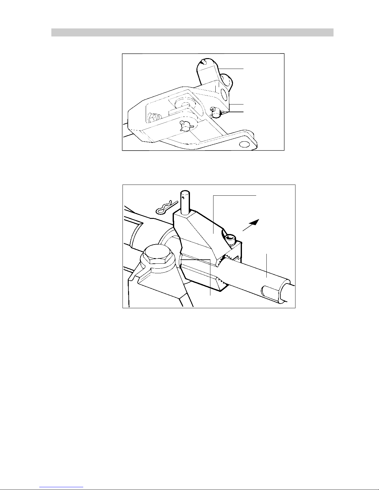
1. Remove the locating pin that attaches the cable rod to the tiller end
block and replace with the girdle support bracket as shown.
Locating bolts
Shakeproof
washers
Split pin
Sprung location
pin
Girdle support
bracket
Adaptor pin
bracket
Safety clip
D744-1
Page 60
Chapter 2: Installation
59
Girdle support
bracket
Tiller end block
Split pin
D745-1
2. Secure the assembly with the split pin (supplied).
3. Install the adaptor pin bracket to the cable end sheath.
Adaptor
bracket
Aft
Cable end
sheath
Shoulder
D925-1
Note:
The adaptor pin bracket must sit against, but not on, the shoulder of
the cable end sheath. Also, it is important that the securing bolts are
sternside of the steering cable end sheath.
4. Ensure that the bracket remains vertical and tighten the locking bolts.
5. Rotate the girdle support bracket so that locator pin is facing
forwards.
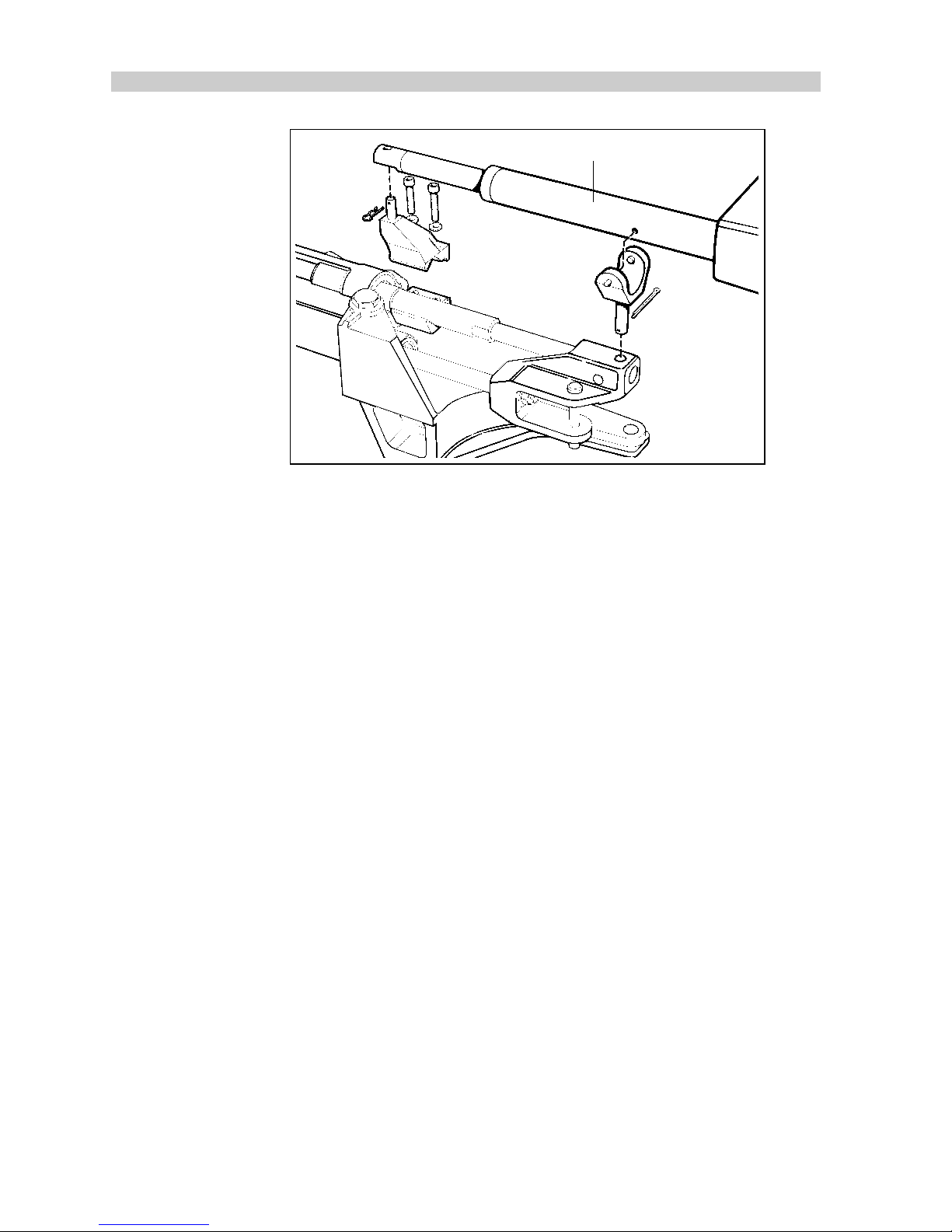
6. Position the stern drive actuator so as to locate the fixed support pin
on the girdle support bracket into the hole in the girdle tube.
Page 61
60
TYPE 100/300 Operation and Installation Handbook
D926-1
Girdle tube
7. Carefully twist and lower the actuator into the girdle support bracket
until the spring pin locates into the opposite side of the girdle tube.
Caution: It is most important that both the solid and spring location pins
are fully engaged in the actuator girdle tube. Failure to do so will result in
autopilot failure and possible steering system damage.
8. Position the drive unit pushrod over the top of the adaptor pin and
secure with the safety clip.
9. Slowly turn the steering system from hard-over to hard-over. The drive
unit and the adaptor pin bracket must not touch any part of the engine
or steering system. This includes any engine hoses that may have
only passing contact with the autopilot actuator; after a time these
will wear and ultimately fail.
Page 62

Chapter 2: Installation
61
Mercruiser/OMC/Yamaha
1. Remove the locating pin that attaches the cable end sheath to the tiller
end block.
2. Replace the locating pin with the girdle support bracket as shown.
Girdle
support
bracket
Tiller
end block
Split
pin
Cable end sheath
R745a-1
3. Secure the assembly with the split pin (supplied).
4. With the helm turned hard to port, assemble the adaptor pin bracket
to the cable end sheath as shown.
D1003-1
Adaptor
bracket
Forward
Cable end
sheath
6.5in (165mm)
Note:
The securing bolts must be on the front or bow of the boat side
cable end sheath. Also, the bracket should be positioned 6.5in (165mm)
from the girdle support bracket.
Page 63
62
TYPE 100/300 Operation and Installation Handbook
5. Make sure that the bracket remains vertical and tighten the two
locating bolts.
6. Rotate the girdle support bracket so that the spring locator pin is
facing forwards.
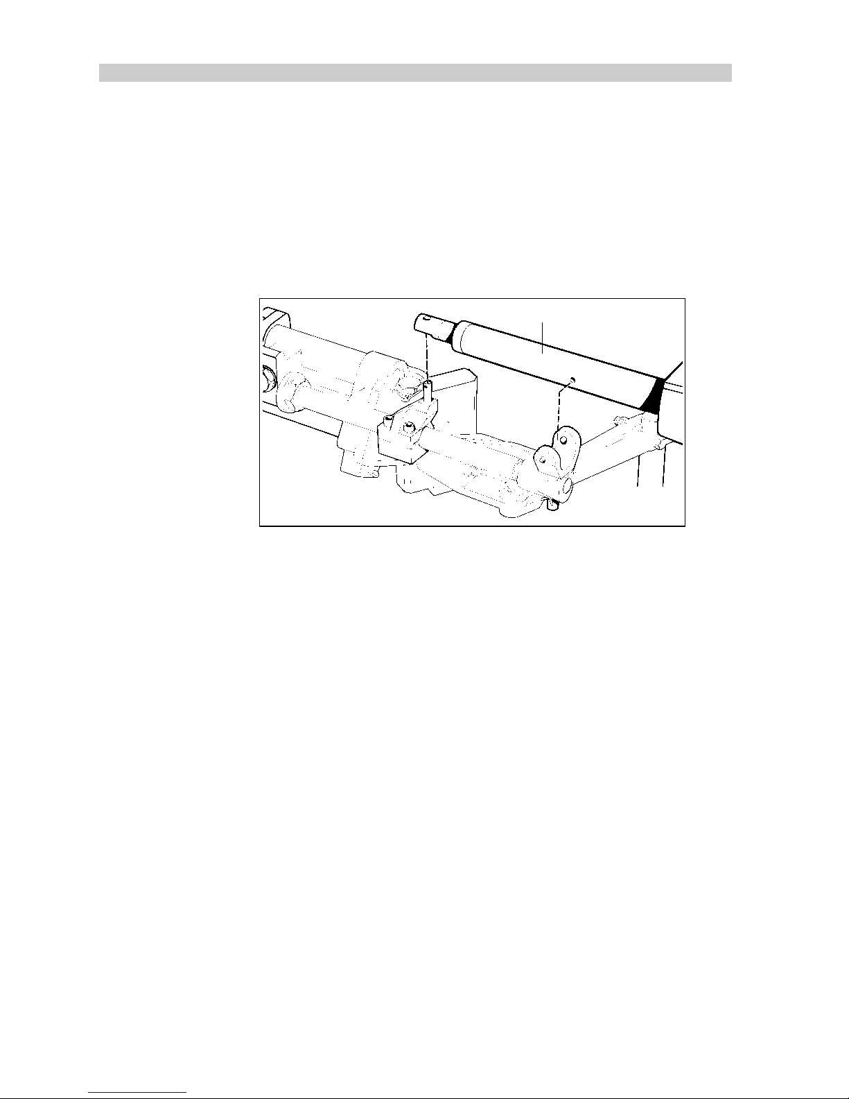
7. Position the stern drive actuator so as to locate the fixed support
pin on the girdle support bracket into its location hole in the girdle
tube.
Girdle tube
D1002-1
8. Carefully twist and lower the actuator in to the girdle support
bracket until the spring pin locates into the opposite side of the
girdle tube.
Note:
Both the solid and spring location pins must be fully engaged in
the actuator girdle tube; failure to do so will result in autopilot
failure.
9. Position the drive unit pushrod over the top of the adaptor pin and
secure with the safety clip.
10. Slowly turn the steering system from hard-over to hard-over.
Note: It is most important that the drive unit and the adaptor pin
Page 64

Chapter 2: Installation
63
bracket do not touch any part of the engine or steering system. This
includes any engine hoses that may have a passing contact with the
autopilot actuator; after a time these will wear and ultimately fail.
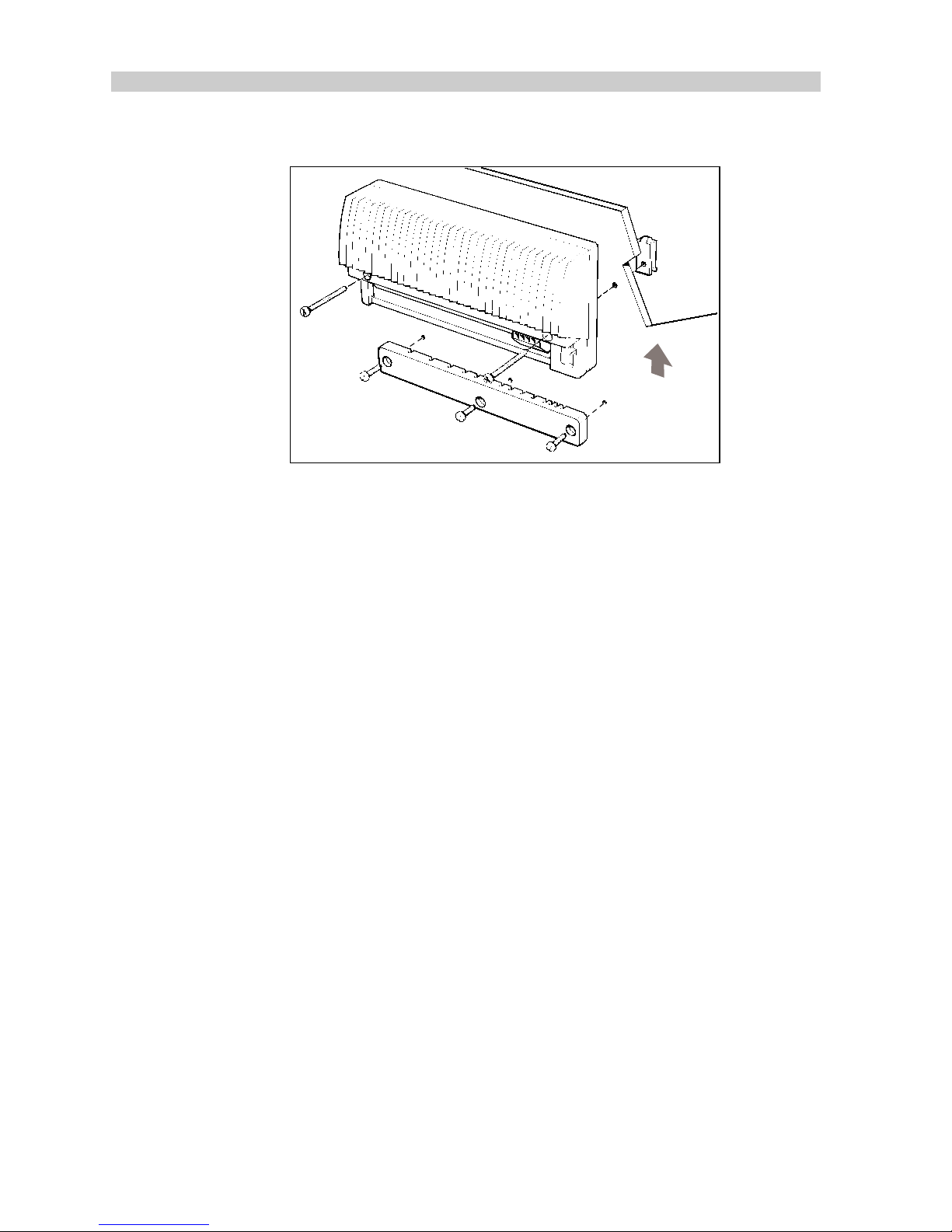
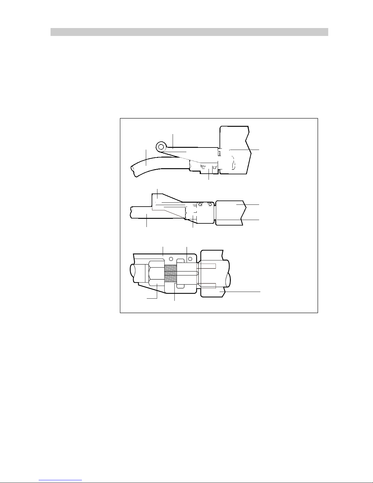
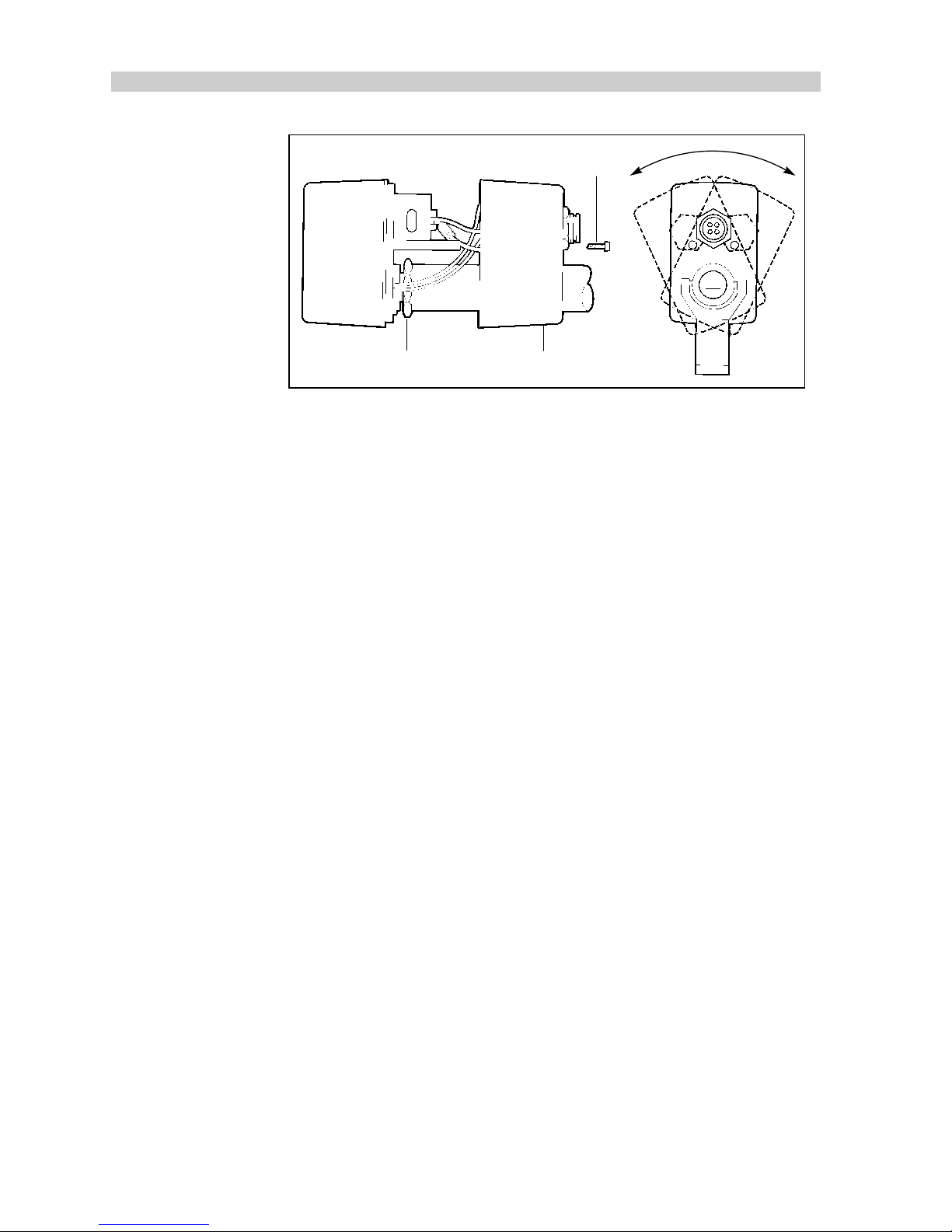
Mounting in a Restricted Area
If an obstruction prevents installation of the drive unit as supplied, the
main body can be rotated relative to the mounting bracket as follows:
1. Remove the two fixing screws and carefully slide the cover
forwards, ensuring that the four cables do not pull away from the
plugs inside the cover.
2. Loosen off the lock nut and rotate the main body as required.
3. Re tighten the lock nut securely, making sure that the lock nut is
no more than one turn from the start of the thread.
4. Replace the cover taking care not to crimp any cables.
5. Using the steering wheel, move from hard over to hard over and
check that no part of the drive unit contacts any part of the vessel/
fittings.
Page 65
64
TYPE 100/300 Operation and Installation Handbook
Front cover
Lock nut
Fixing screw
D409-2
Cabling
1. Plug in the power cable, supplied with the drive unit, making sure
that the connector is locked in place by turning the locking ring
clockwise.
2. Run the cable back to the course computer. Secure the cable
close to the drive unit but allowing sufficient free length to
accommodate the drive unit movement.
3. Once again using the steering wheel to move the rudder from
hard over to hard over, check that the cable does not catch on
any part of the vessel/fittings.
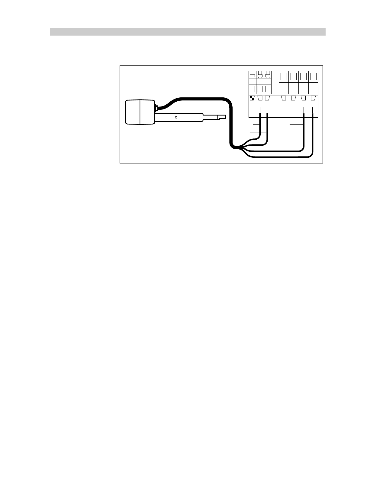
4. The actuator cable has electrical connections for both the drive
motor and the clutch. Connect to the course computer terminals
Page 66
Chapter 2: Installation
65
labelled clutch and motor as shown.
D912-1
lk CLUTCH MOTORPOWER
+–+ –
12
Blue
Brown
Black
Red
2.9 Auxiliary Alarm
The auxiliary alarm is waterproof and, therefore, can be mounted in
any position. A foam seal on the mounting flange ensures a watertight
joint to the mounting surface.
The auxiliary alarm must be connected to the system via an NMEA
interface.
1. Drill a 7/8in (22mm) diameter hole through the mounting panel
as shown.
2. Pass the two way connector block and cable through the drilled
hole.
3. Mount the auxiliary alarm in position using the four self tapping
screws (supplied).
Page 67
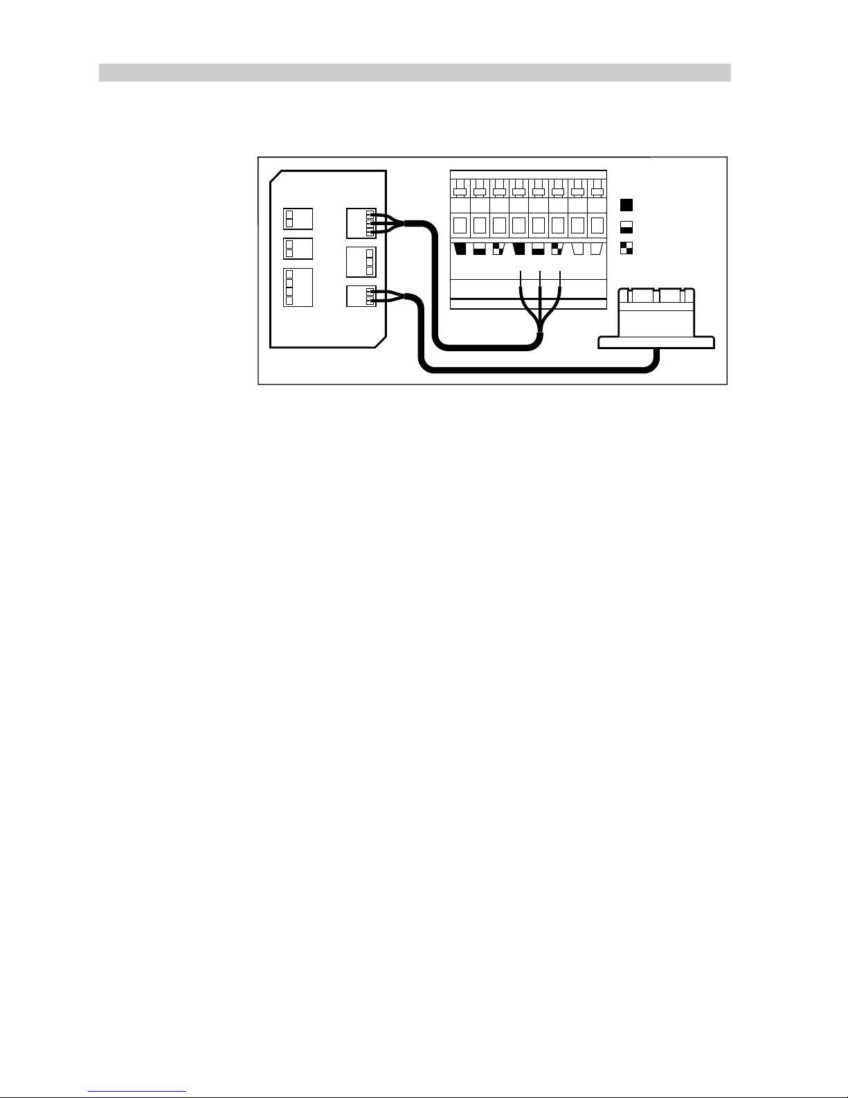
66
TYPE 100/300 Operation and Installation Handbook
Cabling
IN
+ –
NMEA WINDVANE
SEATALKSEATALKALARM
OUT
+ –
D982-1
SeaTalk SeaTalk CLUTCH
+–
Grey (screen)
Red
Yellow
Connect the NMEA interface to the alarm and course computer as
shown.
2.10 Joystick
The mounting surface must be smooth and flat to ensure that there is
adequate waterproofing.
1. Use the template provided to mark the centers for the two fixing
holes and outline of the body aperture.
2. Drill the fixing holes and cut-out the aperture for the body.
3. Remove the mounting template and peel off the protective paper
from the rear of the weather gasket and fix to the mounting
surface.
4. Pass the signal cable through the body aperture and secure the
Joystick with the thumb nuts provided.
Page 68
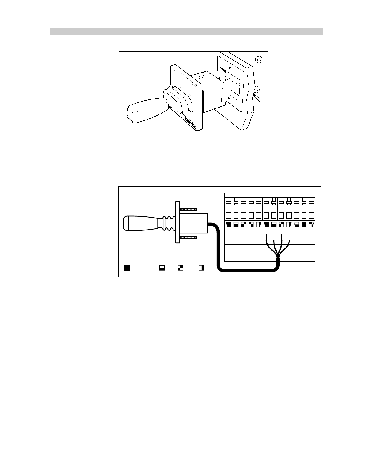
Chapter 2: Installation
67
D1004-1
Cabling
The Joystick is supplied with 26ft (8m) of cable which should be
connected to the course computer as shown.
D984-1
FLUXGATE
JOYSTICK GYRO
Grey (screen) BlueRed Green
Note:
Only one joystick can be connected.
2.11 Masthead Transducer (sail only)
To enable wind information to be made available to the SeaTalk
system, the wind transducer must be connected to the NMEA
interface box.
Page 69
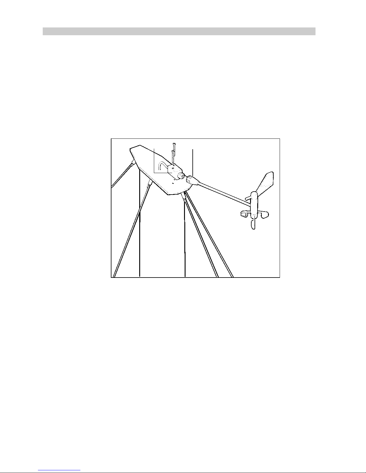
68
TYPE 100/300 Operation and Installation Handbook
Mounting
1. With the threaded end of the mounting block facing forwards,
mark the position for the self tapping screws.
2. Drill the holes using the supplied 4.0mm (5/32in.) drill.
3. Attach the mounting block to the mast using a suitable sealing
compound.
4. Tighten the locking ring securely.
12
D756-1
1 Mounting block 2 Locking ring
Cabling
1. Cut the cable with sufficent length to run from the monting block
to the NMEA interface box.
2. Feed the cable down the mast.
Note:
If the mast is deck stepped the cable should be passed
through the deck and sealed using a proprietry gland fitting.
3. Connect the cable to the NMEA interface box as shown.
Page 70
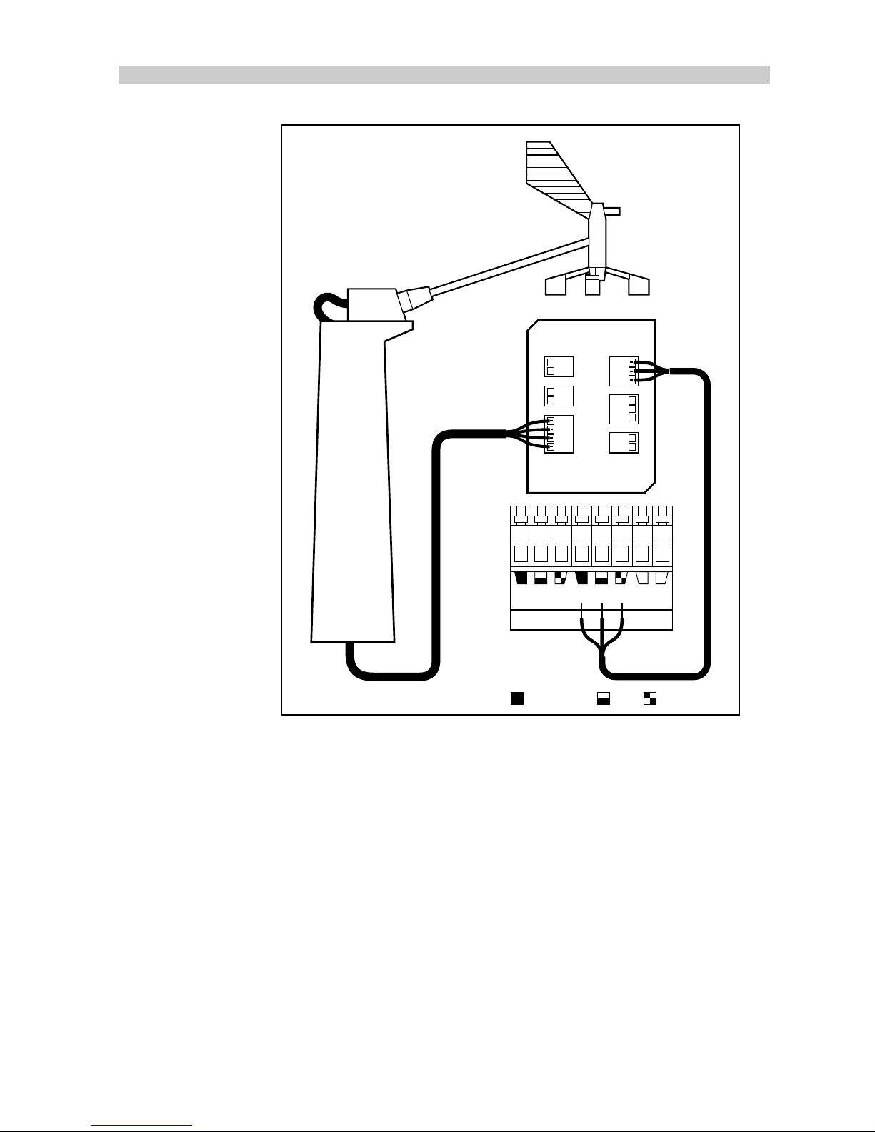
Chapter 2: Installation
69
D1021-1
SeaTalk SeaTalk CLUTCH
+–
IN
+ –
NMEA WINDVANE
SEATALKSEATALKALARM
OUT
+ –
Grey (screen) Red Yellow
Page 71

70
TYPE 100/300 Operation and Installation Handbook
Note:
The yellow connection from the mast head transducer is not
connected at the NMEA interface.
2.12 Interfacing to other manufacturer's equipment (NMEA)
Course Computer NMEA ports
The type 100 and 300 course computers have NMEA 0183 input and
output ports. Sentances decoded are as follows.
Input Port
NMEA 0183 Data NMEA Header Received
Cross Track Error APA, APB, RMB, XTE, XTR
Bearing to Waypoint BPI, BWR, BWC, BER, BEC, RMB, APB
Distance to Waypoint BPI, BWR, BWC, BER, BEC, RMB, WDR, WDC
Waypoint Number APB, BPI, BWR, BWC, BER, BEC, RMB, APA,
WDR, WDC, BOD, WCV
Water Speed
(through the water)
VHW
Apparent Wind Angle VWR
Latitude/Longitude GGA, GLL, GXA, RMA, RMC, GXP, GDF,
GDP, GDA, GOF, GOP, GLF, GLP, GLA
GOA, IMA, GXF
COG/SOG VTG, RMA, RMC, VTA
Variation HDG, RMA, RMC, HVD, HVM
Output Port
Page 72
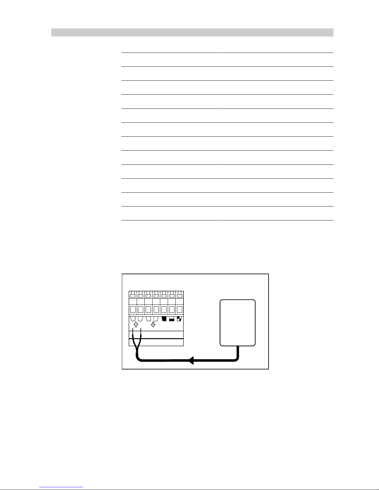
Chapter 2: Installation
71
NMEA 0183 Data NMEA Header Transmitted
Cross Track Error XTE
Bearing to Waypoint BWC
Distance to Waypoint BWC
Waypoint Number BWC
Latitude and Longitude GLL
Magnetic Heading HDG, HDM, HDT
True Heading HDT
Locked Autopilot Heading HSC
Course Over Ground VTG
Speed Over Ground VTG
Fix/No Fix GLL
81004-11
Cabling
Connect the NMEA output from a GPS, Loran, Decca etc. to the
NMEA input terminals on the course computer.
NMEA SeaTalk
+–+–
GPS
Loran
Decca
Type 100/300
Course Computer
D1064-1
NMEA out
Page 73
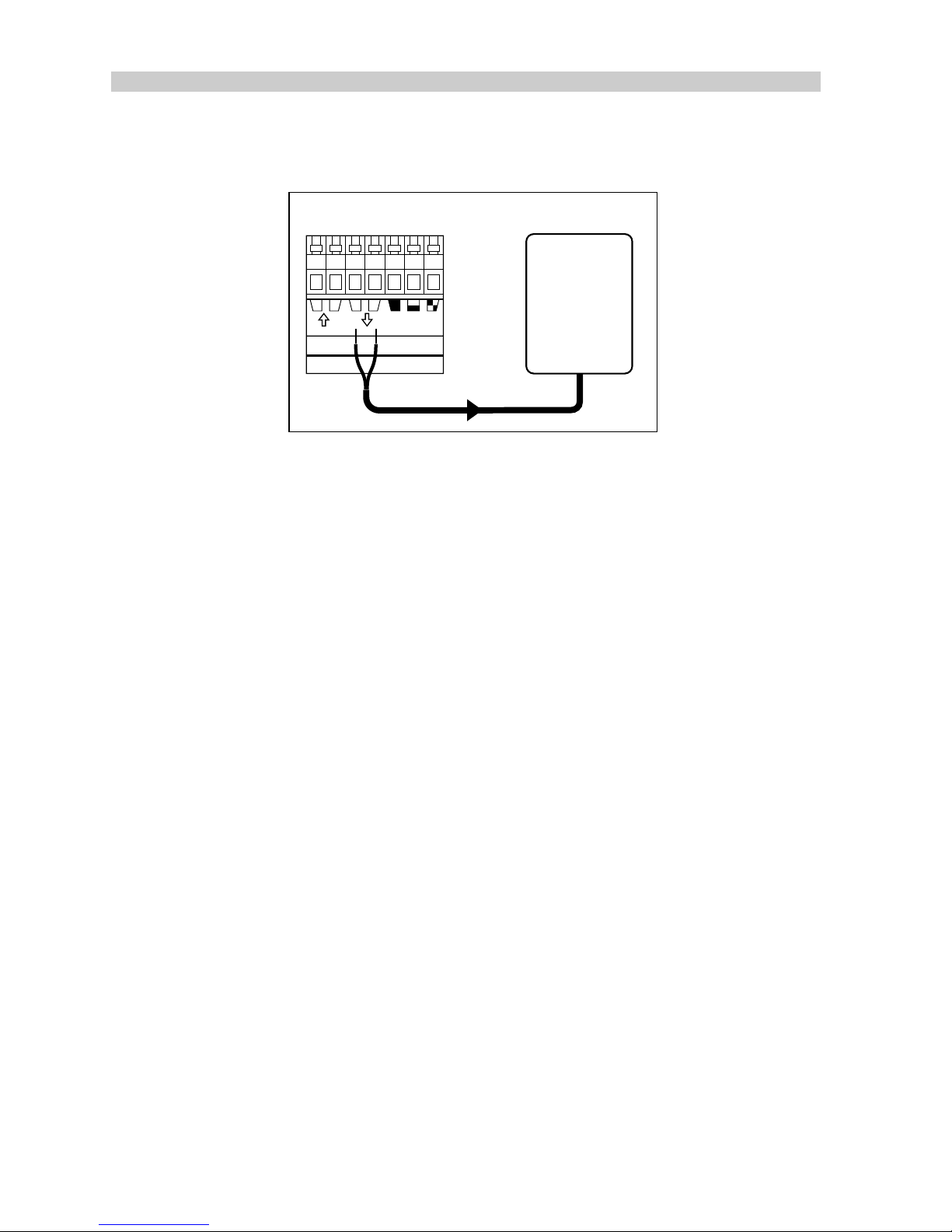
72
TYPE 100/300 Operation and Installation Handbook
Connect the NMEA input on the radar etc. to the NMEA output
terminals on the course computer.
NMEA SeaTalk
+–+–
NMEA in
Radar etc.
Type 100/300
Course Computer
D1065-1
ST6000/ST7000 Control Unit NMEA Input
The ST6000/ST7000 control units are fitted with an NMEA input port.
sentances decoded are as follows.
Page 74
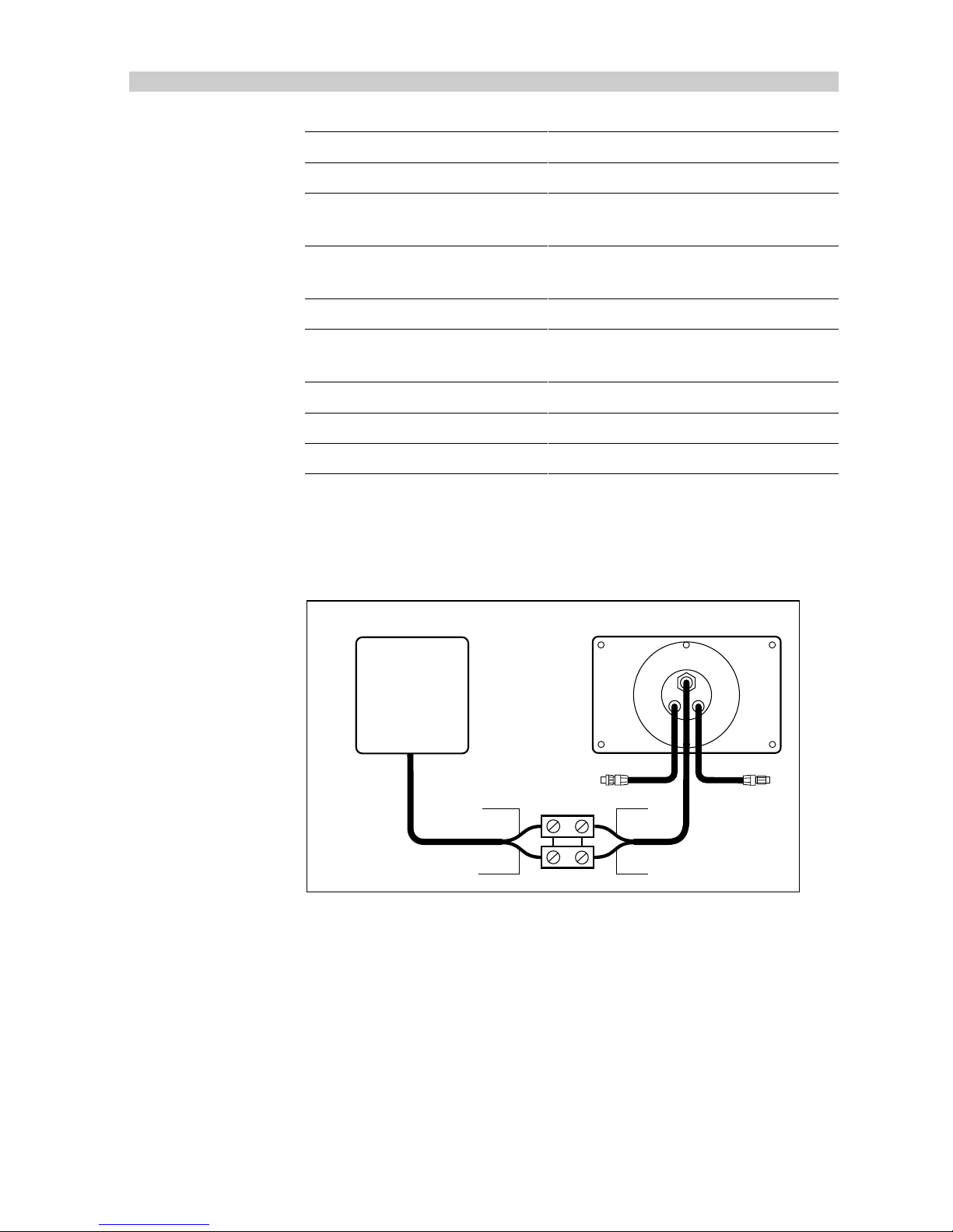
Chapter 2: Installation
73
NMEA 0183 Data NMEA Received Header
Bearing to Waypoint APB, BPI, BWR, BWC, BER, BEC, RMB
Distance to Waypoint WDR, WDC, BPI, BWR, BWC, BER,
BEC, RMB
Waypoint Number APB, APA, BPI, BWR, WDR, BWC,
WDC, RMB, BOD, WCV, BER, BEC
Speed (through water) VHW
Apparent Wind Speed and
Direction
VWR
Latitude and Longitude GLL
COG and SOG VTG
Cross Track Error XTE, XTR, APA, APB, RMB
81004-12
Cabling
Connect the NMEA output from either a GPS, Loran, Decca, Speed
or Wind instrument to the NMEA input on the control unit.
D1066-1
+
+
+
+
+
+
ST7000 Control Unit
Data 0v
Red
Blue
Data tx
NMEA out
GPS
Loran
Decca
Wind Instrument
Speed Instrument
NMEA Interface
The NMEA interface is primarily designed to allow operation with
other manufacturers equipment by providing conversion between
SeaTalk and NMEA 0183 data format. Sentances decoded and
transmitted are as follows:
Page 75

74
TYPE 100/300 Operation and Installation Handbook
Data SeaTalk instrument
required
Transmitted
NMEA
Header
Cross Track Error Navcenter or Navdata or
GPS
APB
Bearing to
Waypoint
Navcenter or Navdata or
GPS
BWC
Distance to
waypoint
Navcenter or Navdata or
GPS
BWC
Waypoint Number Navcenter or Navdata or
GPS
BWC
Apparent wind
speed and
direction
Wind VWR
Boat Speed
(Through water)
Speed or Tridata VHW
Water Depth Depth or Tridata DBT
Longitude and
Latitude
GPS or Navcenter or
Navdata
GLL
Magnetic Heading Compass or SeaTalk
Autopilot
HDM, HDG,
VHW
True Heading Compass or SeaTalk
Autopilot
HDT, VHW
Locked autopilot
heading
SeaTalk Autopilot HSC
Water Temperature Speed or Tridata MTW
Course over the GPS or Navdata or VTG
Page 76
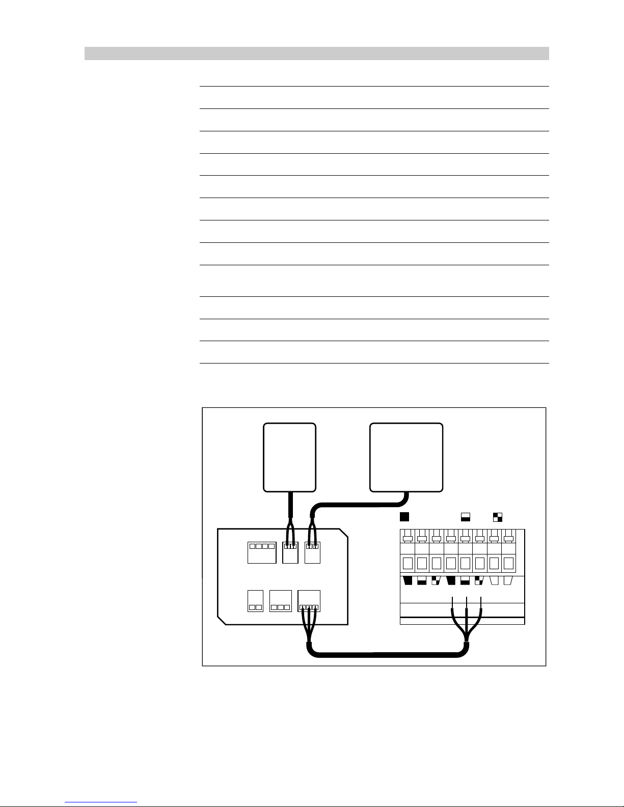
Chapter 2: Installation
75
NMEA 0183 Data NMEA Header Transmitted
Cross Track Error XTE
Bearing to Waypoint BWC
Distance to Waypoint BWC
Waypoint Number BWC
Latitude and Longitude GLL
Magnetic Heading HDG, HDM, HDT
True Heading HDT
Locked Autopilot
Heading
HSC
Course Over Ground VTG
Speed Over Ground VTG
Fix/No Fix GLL
81004-11
Cabling
IN
+ –
NMEA WINDVANE
SEATALKSEATALKALARM
OUT
+ –
D896-1
SeaTalk SeaTalk CLUTCH
+–
Grey (screen) Red
Yellow
Radar etc.
GPS
Loran
Decca
Wind Instrument
Speed Instrument
• Connect the NMEA interface box to the course computer SeaTalk
connection or alternatively any other SeaTalk product using one of
the available interface cables.
• Other manufacturer's equipment can now be connected to the
NMEA in or NMEA out connections.
Note:
Only one transmitter should ever be connected to an NMEA
Page 77

76
TYPE 100/300 Operation and Installation Handbook
Chapter 3: Functional Test
This section provides detailed information related to complete system
testing, equipment calibration and initial sea trials.
3.1 System test
The steering system and drive unit/rudder reference transducer should be
carefully inspected and the following points checked using the steering
wheel to drive the vessels steering from hardover to hardover.
• the steering system reaches the rudder end stops before the drive
actuator reaches its end stops (Linear/Stern Drive).
• no part of the autopilot drive system fouls any part of the steering
system or vessels structure through full travel.
• the mechanical alignment of the drive unit is as specified in this handbook.
• the mechanical alignment of the rudder reference transducer is as
specified in this handbook.
• all connecting wires are secured clear of the bilge and cannot foul any
part of the steering system. All connectors are tightly secured.
• all securing bolts are fully tightened and mechanical locking arrangements as specified are in place.
3.2 Switch-on
Switch on the electrical supply from the main panel. All control units will
emit a short beep and display the autopilot type: either ST6000 or
ST7000. Within 2 seconds Standby will be displayed to indicate that the
autopilot is in Standby mode.
Page 78
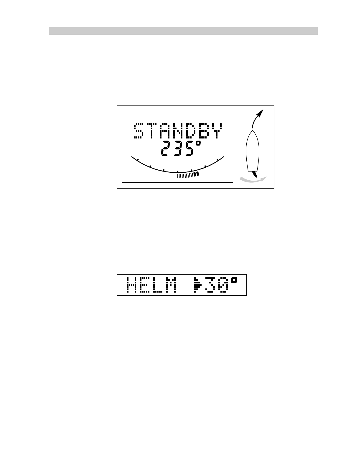
Chapter 3: Functional Test
77
3.3 Rudder angle sense
ST7000 control unit
Move the wheel to produce a starboard turn. The rudder angle display
should move to the right.
RUDDER
0
10
20
30
10
20
30
D1015-1
If the display moves to the left the red and green wires from the rudder
reference transducer must be reversed.
ST6000 control unit
Press Display twice.
Move the wheel to produce a starboard turn. The rudder angle should
increase and the direction indicator (
▼
) be displayed.
D1029-1
If the (▲) rudder angle indicator is displayed the red and green wires from
the rudder reference transducer should be reversed.
3.4 Rudder angle alignment
With the rudder amidships, see if the rudder angle display reads zero.
Misalignment up to +/- 7 degrees can be removed in the calibration
sequence which is explained later in this section. If the misalignment is
greater than 7 degrees the rudder reference should be mechanically
adjusted to be within the +/- 7 degree limit.
Page 79

78
TYPE 100/300 Operation and Installation Handbook
3.5 Operating sense
The operating sense of the autopilot can be checked as follows:
1. Push AUTO.
2. Press the +10 degree key. This should move the rudder a few
degrees to produce a turn to starboard. If the rudder moves
hardover to port, the motor connections at the course computer
should be reversed.
3.6 Rudder deadband
The factory preset rudder deadband level will provide stable rudder
positioning on most steering systems. On some steering systems, where
a rotary or hydraulic drive unit is sited a long way from the rudder, slight
instability may occur. This can be removed by increasing the 'rudder
damping' level in calibration. Any increase should be minimised as it will
reduce the autopilots course keeping accuracy.
3.7 Mechanical test (Linear, Rotary & Hydraulic Drives)
WARNING: When the steering system is being moved manually, or
under drive from the autopilot, do not touch any part of the system.
The forces exerted are considerable and could cause injury.
1. Push AUTO.
2. Press the +10 degree key to drive the rudder hardover onto the end
stops
Note:
This may require increasing the rudder limit in the calibration mode.
3. Make sure the drive unit mounting shows no sign of movement.
4. For hydraulic systems, make sure there is no seepage of hydraulic
fluid and that the steering ram moves smoothly.
Caution: If the installation is a non Autohelm Constant Running
Pump, firstly check that the system includes a pressure relief valve.
Failure to do this could cause damage to the steering system.
5. Repeat driving the rudder hardover to the opposite end stop.
Current limit and cutout
When the rudder is driven onto the end stops the power to the drive will be
cut out after a few seconds - this is normal. Drive will only be restored if the
rudder moves away from the end stop or if drive is required in the opposite
direction.
Page 80

Chapter 3: Functional Test
79
3.8 Mechanical Test (Stern Drive)
It is recommended that the Auto Release facility is used when a Autohelm
mechanical stern drive actuator is installed. This should be switched on in
calibration.
1. Manually drive the steering hardover to starboard
2. With the engines running, engage Auto and, with repeated presses of
the -10 degree key, drive the steering to the opposite lock (port).
3. The autopilot should drive the steering onto the end stops, sound an
alarm, display the 'Release' message and then revert to 'Standby'.
4. Re-engage the autopilot (Auto) and repeat the driving the steering
hardover to starboard using the +10 degree key.
5. The autopilot should again drive onto the end stop, sound an alarm,
display 'Release' and return to 'Standby'.
Note:
If the unit sounds the alarm and displays Release before reaching
the opposite lock, carefully check the vessel’s steering system for any
stiffness or mechanical jamming.
If the condition persists, set the Auto Release function to “off” (0) in
calibration and contact the Product Support Department at Autohelm for
further advice.
Note:
The Auto Release function should always be set to “off” (0) in
calibration if using any drive unit other than a stern drive actuator.
3.9 Setting the Autopilot Rudder Limit (All drives)
Having checked the correct functioning of the drive unit and the appropriate End Stop Cutout/Auto Release function the programmable rudder
angle unit should be set.
The rudder angle limit sets the maximum angle to which the autopilot will
move the rudder. This should be set to just less than the vessel’s mechanical limit stop to avoid putting the steering system under unnecessary load.
Using the rudder angle display whilst manually moving the helm, record
maximum rudder angle in both directions. Set up the rudder angle limit in
calibration mode (see page 82) to 5 degrees less than the minimum angle
recorded.
Page 81

80
TYPE 100/300 Operation and Installation Handbook
3.10 GyroPlus Offset and Drift Compensation
The GyroPlus uses the latest generation solid-state rate gyro to enhance
steering performance at response level 3 (see Calibration for details). Like
all rate gyro's the GyroPlus is subject to offset and drift. However, this is
automatically compensated for whenever the autopilot is in AUTO mode.
When the GyroPlus is initially installed, it is important that offset and drift
compensation ( a once-only operation) is carried out before selecting
response level 3 - failure to carry out this procedure will result in rapid
course changes when level 3 is selected.
Procedure
Compensation for offset and drift is achieved by simply using the autopilot
in response level 1 or 2 for at least 5 minutes before you select level 3.
Alternatively, if you want to use response level 3 as soon as you engage
AUTO, then the following procedure must be carried out.
1. Moor the vessel so that the heading remains constant.
2. Press AUTO and leave for at least 5 minutes.
3. After 5 minutes, press STANDBY to return to "standby" mode. The
autopilot will nor have stored the compensation value for future use.
Page 82

Chapter 4: Calibration
81
Chapter 4: Calibration
4.1 Recommended Settings
As supplied the ST7000 can be switched on and tested safely without any
adjustments to the factory calibration settings.
The table below lists the suggested settings for sailing/power displacement and planing power vessels. These will provide good performance for
initial sea trials and can be fine tuned later to optimise performance.
Vessel Type
Displacement
Factory Preset
Planing
Set to
Rudder Gain (level) 5 4
Rate Gain (level) 7 4
Rudder Angle Limit
(degrees)
30 30
Turn Rate Limit
(degrees/sec)
20 12
Cruise Speed (knots) 8 25
Off Course Alarm
(degrees)
20 20
Trim Level 1 3
Autopilot Drive Unit Type
Mechanica
Drive
Stern
Drive
Hydraulic
Drive
Hydraulic
Linear
Factory
Preset
Set to Set to Set to
Drive Type 3 3 4 3
Rudder
Position
Deadband
(level)
1 1 1 3
Auto Release off on off off
Page 83
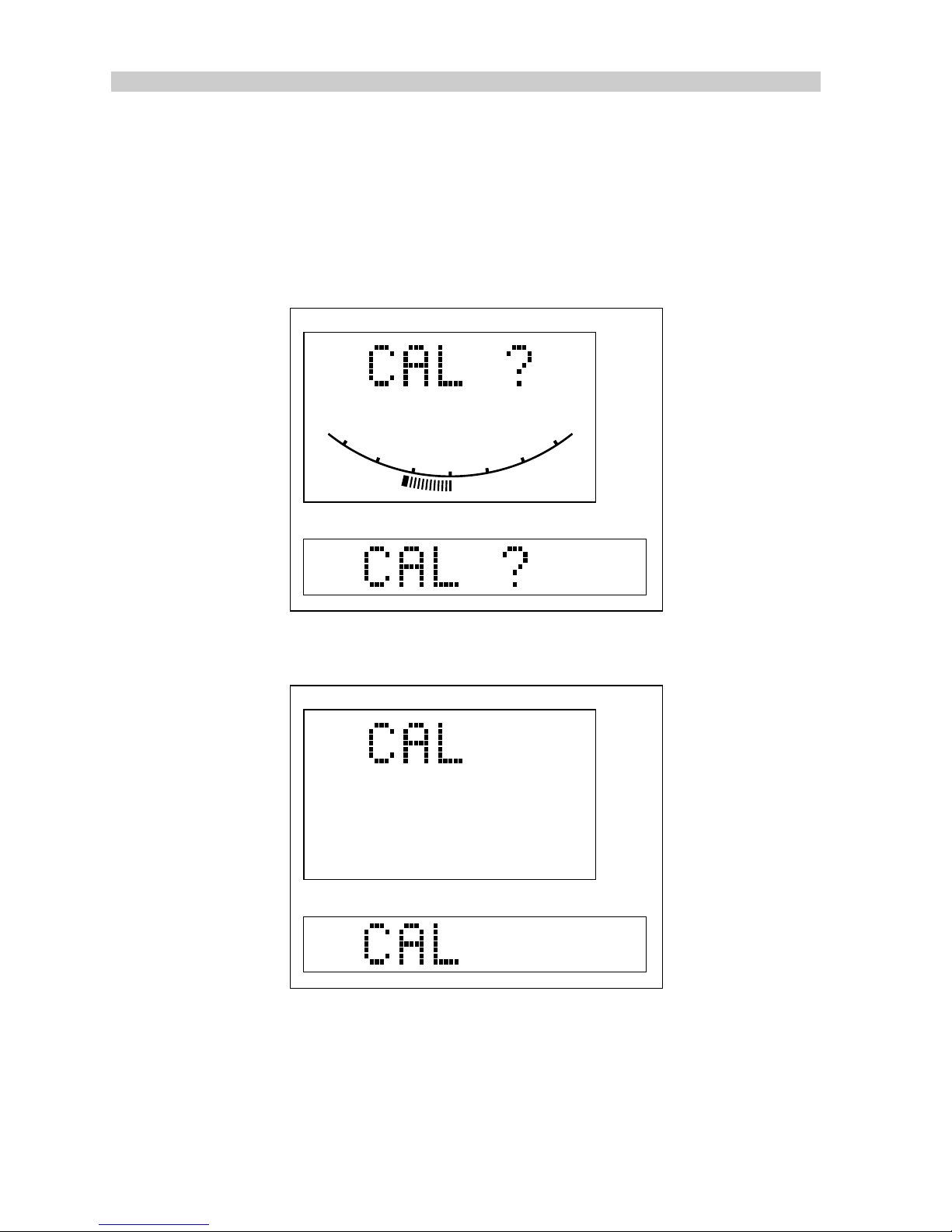
82
Type 100/300 Operation and Installation Handbook
4.2 Selecting calibration
To select calibration:
• Press Standby.
• Press and hold Track and Display for 2 seconds to access the
following display.
D1030-1
RUDDER
0
10
20
30
10
20
30
ST6000
ST7000
• Press and hold Track and Display for a further 2 seconds to access
the following display.
D1031-1
ST6000
ST7000
Cal.
Cal.
Page 84

Chapter 4: Calibration
83
4.3 Adjusting calibration
In calibration the Display key is used to scroll through the menu. The
displayed value is adjusted using the Response keys (hold down for fast
scroll).
Note:
If the 'CAL' display reappears at any time during calibration, press
Display to advance to the next menu level.
Once calibration has been carried out, further adjustment can be made at
any time.
Rudder Gain
Rudder Gain controls the amount of rudder the pilot will apply to turn onto
a new heading. A correctly set rudder gain will, for example, turns the
vessel crisply onto the new heading with an overshoot of no more than 2 to
5 degrees for a 40 degree course change. A high rudder gain setting will
result in oversteer, recognized as an overshoot of more than 5 degrees.
A rudder gain level that is too low will result in understeer giving poor
steering performance.
WARNING: It is most important that the rudder gain is correctly set
on planing craft. Incorrect adjustment will lead to poor steering
performance and is dangerous at high speeds.
The settings available are as follows:
Range 1 to 9
Recommended
setting
5 (Displacement)
5 (Semi displacement)
4 (Planing)
3 (Stern drive)
81004-17
Page 85

84
Type 100/300 Operation and Installation Handbook
Rate Level
Rate level controls the amount of rudder the pilot will apply to reduce the
speed at which the vessel is turning. This is also known as counter rudder,
and is only used in response level 3.
The settings available are as follows:
Range 1 to 9
Recommended
setting
7 (Displacement)
7 (Semi displacement)
7 (Planing)
5 (Stern drive)
81004-18
Rudder Offset (Helm Adjust)
Rudder Offset sets the control head to read zero degrees of rudder when
the helm is positioned amidships.
The range available is as follows:
Range -7 to +7 degrees
Default Setting 0
81004-19
Rudder Limit
Rudder Limit restricts autopilot rudder movement to just less than the
steering systems mechanical stops. This avoids putting the steering
system under unnecessary load.
The range available is as follows:
Range 15 to 40 degrees
Default setting 30 degrees
81004-20
Page 86

Chapter 4: Calibration
85
Turn Rate
Turn Rate is the rate in degress per second at which the vessel will turn
when course changes are made via the autopilot.
The settings available are as follows:
Range 5 to 20 degrees per second
Default setting 20 degrees (Displacement)
15 degrees (Semi displacement and
planing)
8 degrees (Stern drive)
81004-21
Turn Rate limit does not apply in power steer or joystick modes.
Cruise Speed
Cruise Speed should be set to the vessel's normal cruising speed and is
used in track mode.
Note:
If boat speed is available on either the SeaTalk bus or via the NMEA
input this will be taken and used in preference to the Calibration Cruise
Speed.
The range available is as follows:
Range 4 to 60 knots
Recommended
setting
6 (Displacement)
8 (Semi displacement)
20 (Planing)
20 (Stern drive)
81004-22
Off Course Limit
Off Course Limit warns you if the autopilot is unable to maintain its set
course and has subsequently strayed more than the set limit for more than
20 seconds.
The off course alarm settings available are as follows:
Range 15 to 40 degrees
Default setting 20 degrees
81004-23
Page 87

86
Type 100/300 Operation and Installation Handbook
Trim Level
Trim Level sets the level for automatic trim which applies additional rudder
to correct for unbalanced propeller torque on twin engine installations, or
weather helm.
The Trim Level settings available are as follows (rate of trim increases with
trim level):
Range 0 to 4
Default setting 2 (Displacement)
3 (Semi displacement, planing and
stern drive)
Joystick Mode (Manual Type)
Power steer selects the Joystick mode of operation: Proportional or ‘BangBang’.
Proportional applies rudder in proportion to Joystick movement - the
further the Joystick is held over the greater the applied rudder.
Bang-Bang applies continous rudder drive in the direction of lever movement. To improve control the speed of rudder movement changes with the
angle of the lever. For maximum speed push the lever hardover. If the lever
is returned to the center position the rudder will remain in its current
position.
The settings available are as follows:
Range 0
1
2
OFF
(Proportional)
(Bang-Bang)
Default setting 1
81004-25
Drive Option
Drive Option sets the type of drive used by your vessel: mechanical with
rudder reference or hydraulic with rudder reference.
The settings available are as follows:
Range 1 to 4
Default setting 1 Future use
2 Future use
3 (Displacement and stern drive)
4 (All hydraulic installations)
81004-26
Page 88

Chapter 4: Calibration
87
Rudder Deadband (Rudder Damping)
The factory setting for Rudder Deadband provides stable rudder positioning on most steering systems. However, some steering systems that use
a rotary or hydraulic drive unit a long way from the rudder may experience
slight instability. This instability can be minimised by increasing the setting.
The settings available are as follows:
Range 1 to 9
Default setting 1
81004-27
Magnetic Variation
Variation tells other equipment the level of magnetic variation present at
the boats current position. Local variation should be entered using the
appropriate keys.
The settings available are as follows:
Range 30 degrees West to 30 degrees East
Default setting Off
81004-28
Auto Adapt
It may be noticed that the autopilot tends to be a little less stable on
northerly headings in higher latitudes of the northern hemisphere and
southerly headings in the southern hemisphere. This is caused by the
increasing angle of dip of the earth’s magnetic field at higher latitudes. This
has the effect of amplifying the rudder gain on northerly (southerly)
headings, affecting all magnetic compasses and getting worse the further
away from the equator you are.
The autopilot is able to compensate for this and provide precise course
keeping on all headings by automatically adjusting the gain of the autopilot
depending on the heading.
It is recommended that for high speed craft the Auto Adapt facility is
selected. This automatically reduces the effects of Northerly/Southerly
heading instability.
This feature is selected in calibration by entering the vessel’s operating
latitude. When selected it automatically adjusts the Rudder Gain depending
on heading removing the need for manual adjustment.
Page 89

88
Type 100/300 Operation and Installation Handbook
Note:
If Auto Adapt is not selected manual adjustment of rudder gain is
normally required when going from Northerly to Southerly headings or vice
versa. Failure to do so can lead to poor course keeping.
The settings available are as follows:
Range 0: Off
1: North
2: South
Default setting 1: North
81004-29
Latitude
Latitude is used to compensate for Northerly/Southerly headings errors.
The settings available are as follows:
Range 0 to 80 degrees
Default setting 0 degrees
81004-30
Wind Trim
Wind trim varies the response of the autopilot in Vane mode.
Range
1 -- Fast response
2 -- Slow response
Default setting 1
81004-31
Response Level
This sets the response level when the pilot is switched on.
The settings available are as follows:
Range Level 1: Automatic sea state control
Level 2: Automatic sea state inhibit
Level 3: Automatic sea state inhibit
counter rudder
Default setting Level 1
Page 90

Chapter 4: Calibration
89
Auto Release (manual override)
Auto Release provides emergency manual override, should it be necessary, for example, to avoid an obstacle at the last moment. It is used with
an Autohelm stern drive actuator. For all other drive systems Auto release
should be turned off.
The settings available are as follows:
Range 0 = Off
1 = On
Default setting N/A (Displacement)
N/A (Semi displacement)
N/A (Planing)
1 (On) (Stern drive)
81004-33
4.4 Saving Calibration Mode
To exit calibration mode and save all changes, press and hold Track and
Display for 2 seconds.
Changes made to calibration settings can, while still in the calibration
mode, be cancelled by quitting as follows:
Press Standby.
Page 91
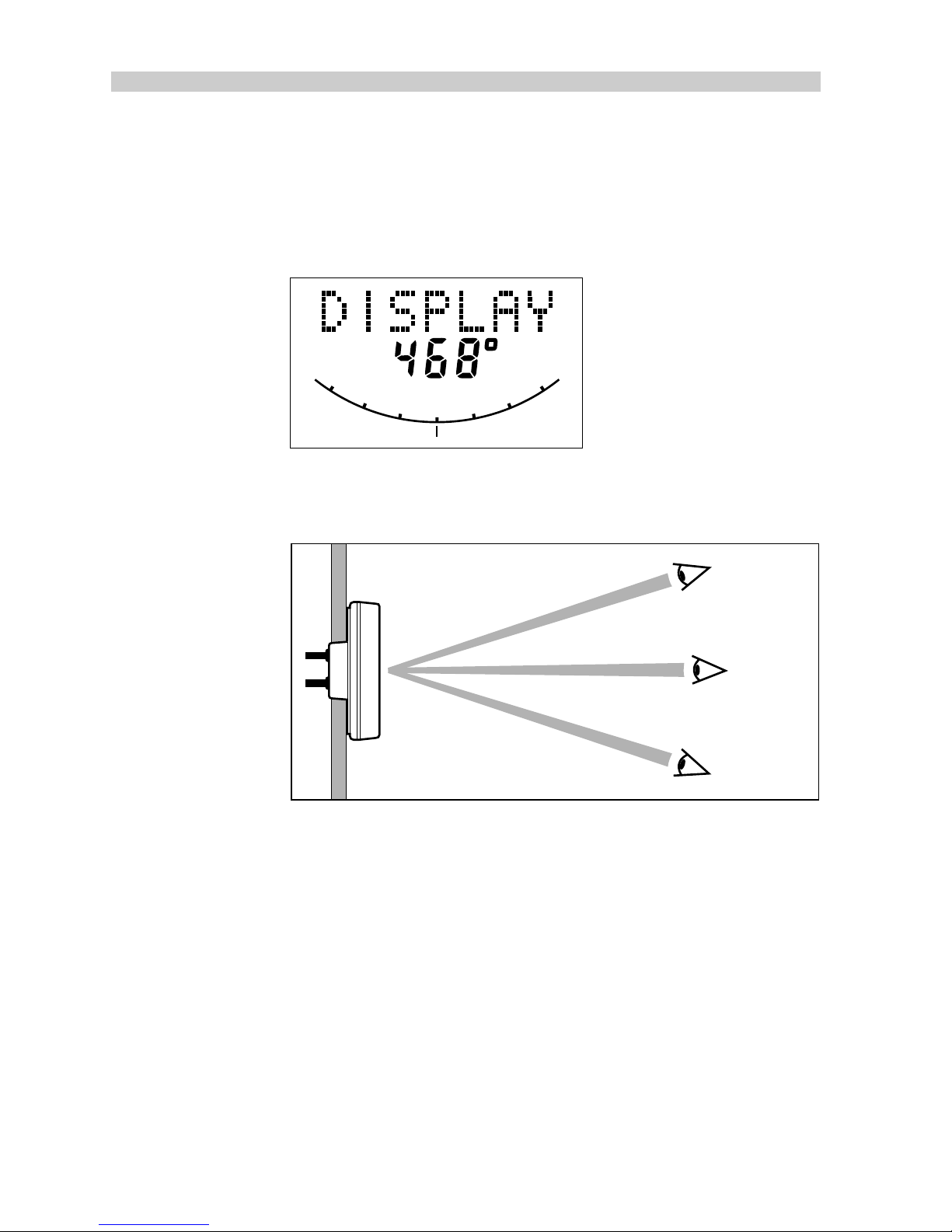
90
Type 100/300 Operation and Installation Handbook
4.5 Display Contrast Adjustment (ST7000 only)
The contrast of the LCD display can be adjusted to suit a wide range of
viewing angles.
• Press Display and Track together momentarily.
RUDDER
0
10
20
30
10
20
30
Cal.
D1016-1
• Press Response (▲) to increase contrast (suits viewing from below).
• Press Response (▼) to decrease contrast (suits viewing from above).
D1017-1
Normal
viewing
position
Increase
contrast ratio
Decrease
contrast ratio
To store the contrast selection, press Display and Track together
momentarily.
4.6 Permanent Watch Alarm (SFIA)
If a permanent watch alarm is required, please contact the Autohelm
Product Support Department or an authorised dealer for further information.
4.7 Recording Calibration Settings
Having fined tuned the calibration settings during initial sea trials, record
them in the following table for future reference.
Page 92
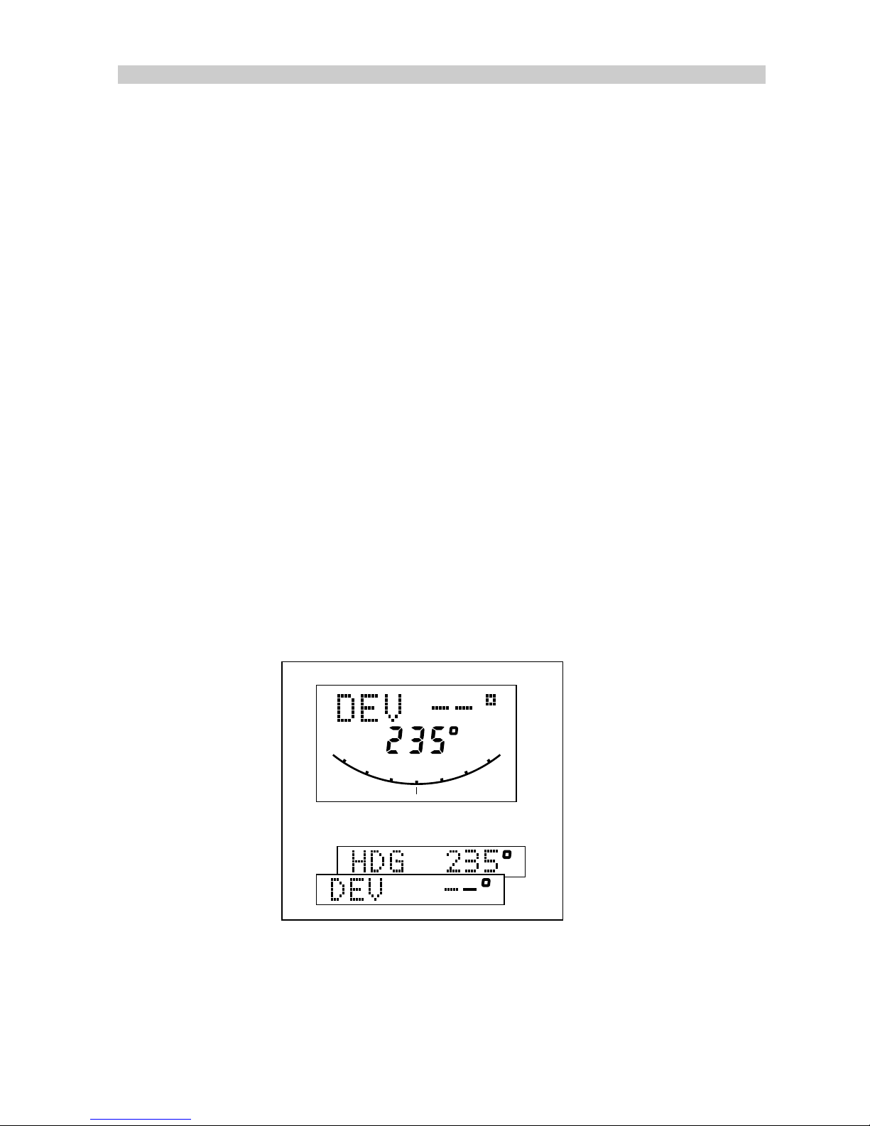
Chapter 5: Initial Sea Trials
91
Chapter 5: Initial Sea Trials
5.1 Initial Sea Trials
Initial sea trials should be carried out in calm conditions with plenty of sea
room. As the vessel will be constantly changing heading, it is most
important to maintain a constant look out.
Before sea trials:
• Read the Operating section of this manual.
• Carry out the system test to verify that the autopilot is operating
correctly.
5.2 Automatic Compass Heading Alignment and Deviation Correction
The displayed compass heading requires alignment with the ships
compass. Until this procedure is carried out, the autopilot compass
display will not agree with the ships compass.
The autopilot will correct the fluxgate compass for most deviating
magnetic fields. This correction procedure should be carried out in calm
conditions preferably in flat water.
To select compass heading alignment and correction, push and hold
STANDBY for 2 seconds until the display shows:
RUDDER
0
10
20
30
10
20
30
Cal.
Cal.
Cal.
ST7000
ST6000
D1019-1
1. Press DISPLAY
2. Keeping boat speed below 2 knots, turn the vessel slowly so that it
takes at least 3 minutes to complete 360 degrees.
Page 93
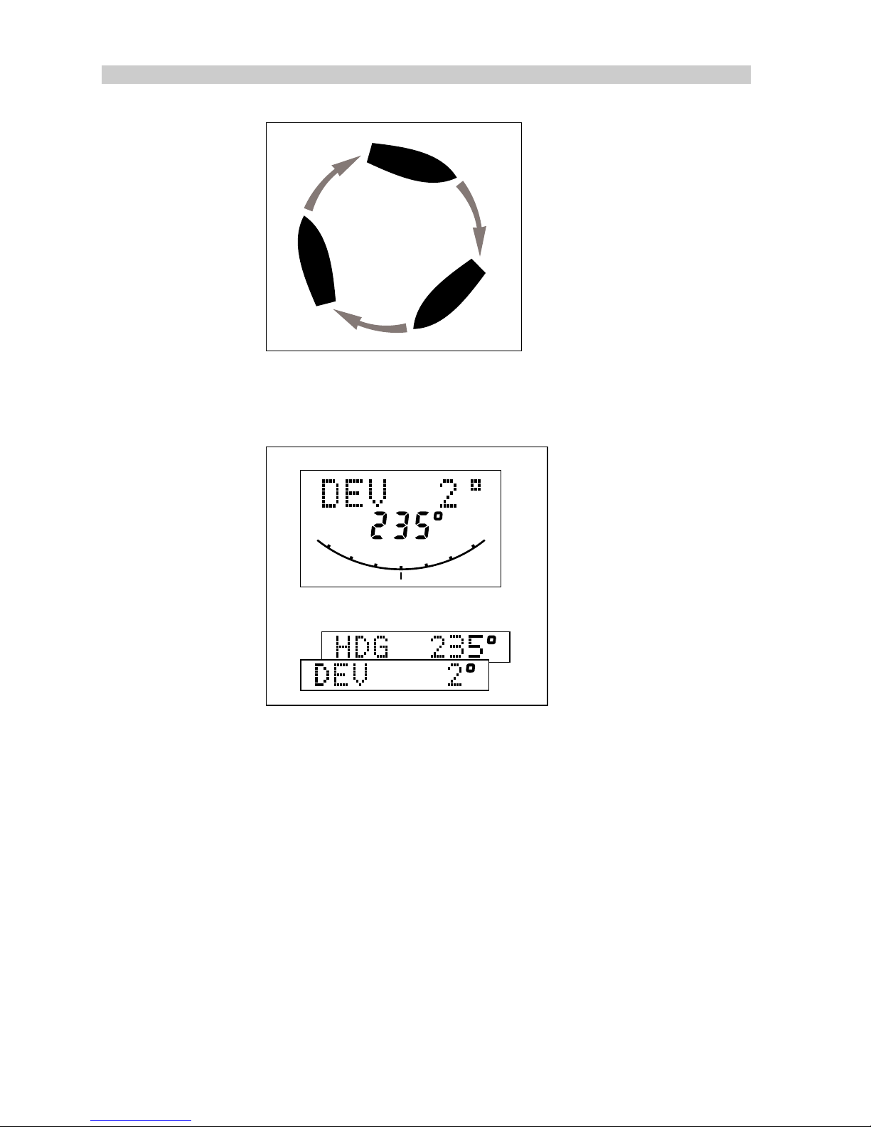
92
TYPE 100/300 Operation and Installation Handbook
D919-1
Keep turning until the display changes to show the amount of deviation the
autopilot has corrected. This can take up to 2 full turns depending on the
amount of deviation found.
RUDDER
0
10
20
30
10
20
30
Cal.
Cal.
Cal.
ST7000
ST6000
D1019a-1
Note:
If the deviation exceeds 15 degrees, you should relocate the
fluxgate compass.
3. Steady the boat up on one heading and use the course change keys
to adjust the displayed heading until it agrees with the steering
compass or a known transit bearing.
4. To exit fluxgate alignment/correction and store the settings, push and
hold STANDBY for 2 seconds until the pilot returns to ‘STANDBY’
mode.
5. To exit fluxgate alignment/correction without saving any new settings,
push STANDBY momentarily.
Page 94

Chapter 5: Initial Sea Trials
93
5.3 Compass Alignment (without deviation correction)
It is possible to change the alignment between the fluxgate and the ship's
compass without carrying out the automatic deviation correction. Proceed
as follows:
1. Push and hold STANDBY for 2 seconds to select fluxgate alignment/
correction mode.
2. Use the course change keys to adjust the heading displayed.
3. To exit fluxgate alignment/correction and store the new setting push
and hold STANDBY for 2 seconds until the pilot returns to ‘STANDBY’
mode.
4. To exit fluxgate linearisation without saving the new setting push
STANDBY momentarily.
5.4 First Sea Trials
In clear waters, steer the boat on to the required heading.
1. Hold the course steady for 5 to 10 seconds.
2. Press AUTO to lock onto the current heading. In calm conditions a
perfectly constant heading will be maintained.
3. Alter course to port and starboard using the course change keys on
any control unit. Course changes should be prompt and without any
sign of overshooting.
4. Press STANDBY to disengage the autopilot for return to hand
steering.
Page 95

94
TYPE 100/300 Operation and Installation Handbook
5.5 Response Control
There are three response levels to provide tighter than normal course
keeping when there is restricted sea room. Select each level in turn and
observe the autopilot activity.
Level 1 - Automatic Sea State Control
• This provides the optimum compromize between power consumption
and course keeping accuracy and is suitable for most situations.
The automatic sea state control can be observed during the sea trial.
• When the autopilot is initially engaged in Auto mode it will respond to all
pitch and roll movements.
• During the first minute of operation, it will be noticed that repetitive
movements of the vessel are gradually neglected until finally the
autopilot will respond only to true variations in course.
• To ensure precise course adjustments the sea state control is automatically reset whenever the course change knob is adjusted.
Level 2 - Automatic Sea State Inhibit
• Where increased course keeping accuracy is required the automatic
sea state control can be inhibited by moving to response level 2.
• Autopilot activity and therefore power consumption will be increased.
Level 3 - Automatic Sea State Inhibit and counter rudder
• Where maximum course keeping accuracy is required a Rate Gyro
transducer should be fitted. This introduces counter rudder (rate) to
increase the natural damping of the vessel. On power craft level 3 is
useful at slow speed where the natural damping of the vessel is
reduced. Autopilot activity and therefore power consumption will be at a
maximum.
The minimum response level necessary to achieve the desired course
keeping should be used to reduce power consumption and autopilot wear
and tear.
Page 96

Chapter 5: Initial Sea Trials
95
5.6 Automatic Trim Control
The autopilot automatically corrects for trim. No adjustment of the pilot is
necessary.
After each course change the automatic trim is cancelled and the autopilot
will re-establish the correct trim for the new heading. It should be noted
that if a large course change is keyed in(greater than 60 degrees) the
autopilot will not assume the final selected course immediately. The vessel
will come to within say 10 degrees of the desired course and will only
settle onto course when the automatic trim has been fully established. This
may take up to two minutes.
It is recommended the following procedure is adopted for large course
changes:
• Note required heading
• Select STANDBY and steer manually
• Bring vessel onto new heading
• Select AUTO and let vessel settle onto course
• Bring to final course with 1 degree course change increments
It is sound seamanship to make major course changes only whilst steering
manually. In this way any obstructions or other vessels may be cleared
properly and due account taken of the changed wind and sea conditions
on the new heading prior to engaging the autopilot.
Note: If the autopilot trim control is switched off, regular checks on the
vessel's heading should be made as changes in standing helm will change
the course steered by the autopilot.
Page 97
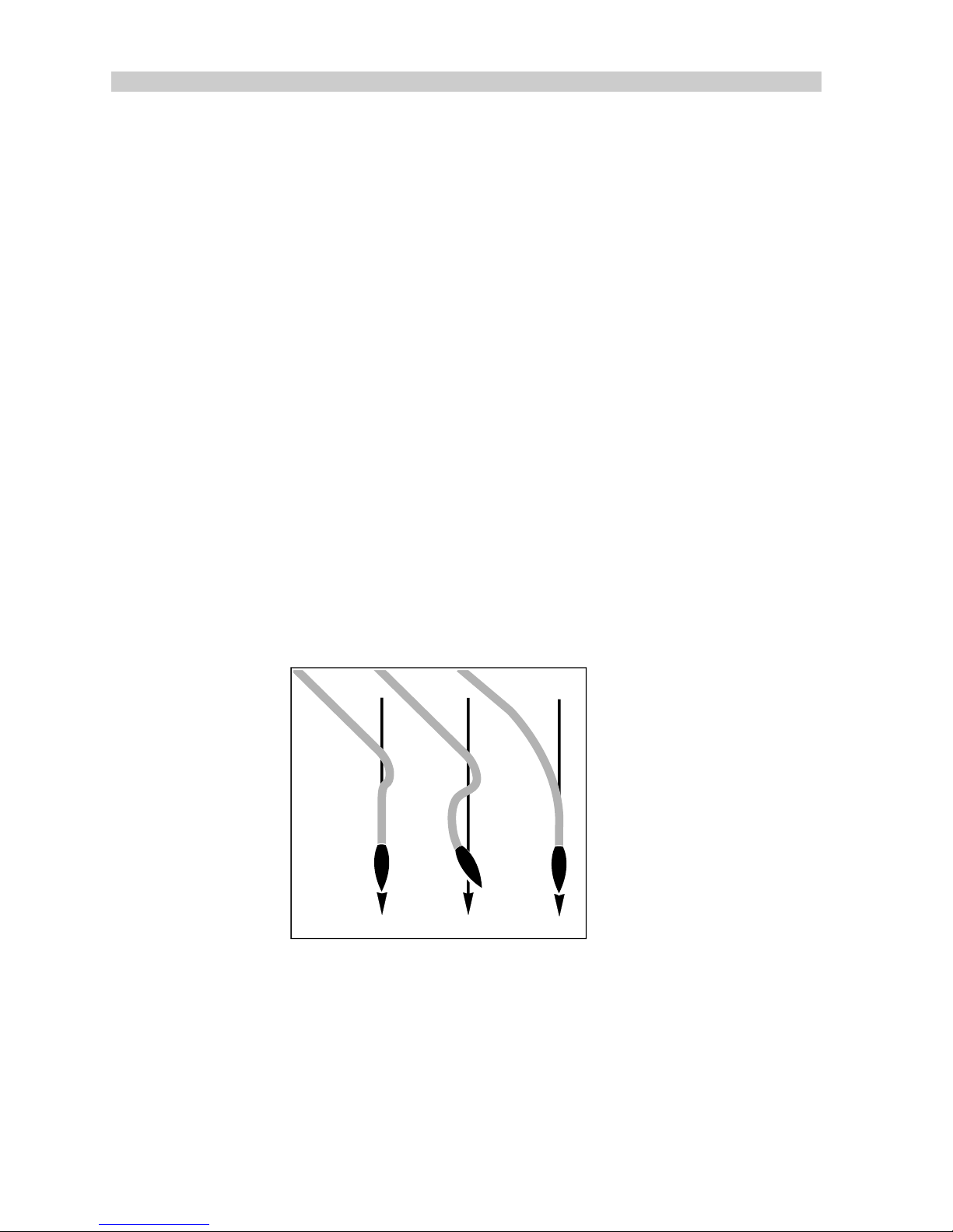
96
TYPE 100/300 Operation and Installation Handbook
5.7 Rudder Gain Adjustment (Displacement Craft)
The factory set rudder gain level provides stable control for initial sea
trials. However, vessels can vary widely in their response to the helm, and
further adjustment to the rudder gain may improve the autopilot’s steering
characteristics. Rudder gain should be set in Response level 1.
An excessively high rudder control setting will result in oversteer, which
can be recognized by the vessel swinging from side to side of the
automatic heading, accompanied by excessive rudder movement. In
addition, distinct overshoot will be observed when the course is changed.
This condition can be corrected by reducing the rudder setting.
Similarly, an insufficient rudder control setting results in understeer which
gives sluggish steering performance and is particularly apparent when
changing course. This is corrected by increasing the rudder setting. These
tendencies are most easily recognized in calm sea conditions where wave
action does not mask basic steering performance.
Typically, if at cruising speed a course change of 40 degrees results in an
overshoot of between 2 - 5 degrees, the rudder gain is correctly adjusted.
Push either RESPONSE key for access to Rudder Gain. Adjust either side
of the calibrated setting to provide optimum autopilot steering.
Correct
rudder
setting
Rudder
setting
too high
New
heading
New
heading
R173/2-1
Rudder
setting
too low
New
heading
AB
Note:
Once the optimum setting has been found, the default calibration
setting for rudder gain should be changed.
Adjustment with Response Level 3
Response level 3, by default, automatically sets the gain to 3 settings
above the gain at response level 1. This can be adjusted as follows:
Select response level 3 and then scroll to the gain display. Adjust the
value as required and save the new value by pressing the up and down
response keys together momentarily.
Page 98

Chapter 5: Initial Sea Trials
97
5.8 Rudder Gain Adjustment (High Speed Planning Craft)
Warning: It is particularly important that the Rudder Gain is correctly set
on high speed craft. Incorrect adjustment will lead to poor steering
performance and is a dangerous condition at
high speed.
Adjust as follows:
• Set to Rudder Gain for optimum steering performance at the vessels
normal cruising speed.
• Push either RESPONSE key for access to Rudder Gain. Adjust either
side of the calibrated setting to provide optimum autopilot steering.
5.9 Rudder Gain - Adjustment with Speed
Due to the significant differences in dynamic stability between planing and
non-planing conditions, most high speed craft require Rudder Gain
adjustment when going from planing to displacement speeds or vice
versa. The required adjustment can be achieved automatically
or manually.
• When the autopilot is used with the speed input from an Autohelm
SeaTalk Speed instrument or is receiving boat speed via its NMEA
input. Rudder gain is automatically adjusted with boat speed. After
setting the gain at planing speed no further manual adjustment should
be required.
Warning: When speed information is fed to the autopilot via the
NMEA input always check the displayed speed is close to the
actual boat speed before locking the autopilot onto a heading.
Delays in data transmission could result in the 'pilot' applying too
much rudder after a large change in vessel speed.
• If no Speed input or NMEA is available manual adjustment should be
carried out to the Rudder Gain setting via the Response keys adjusting
as follows:
1. Speed decreases from planing to displacement
- Increase gain by 1 or 2 levels.
2. Speed increases from displacement to planing
- Decrease gain by 1 or 2 levels.
Warning: The manual gain adjustment must be made after
reducing from planing to displacement speed and before
increasing from displacement to planing speed.
Page 99

98
TYPE 100/300 Operation and Installation Handbook
5.10 Manual Override (Stern Drive Actuators only)
Manual override should be selected in calibration only on installations
fitted with the stern drive actuator. When it has been selected, the
autopilot can be overridden to allow hand steering by turning the steering
wheel. This will return the autopilot to Standby and sound the control unit
buzzer for 10 seconds. There is a slight delay before the autopilot will
return to Standby.
CAUTION: Excessive force is not required and will not reduce this delay.
With the autopilot in Auto and clear of obstruction, turn the steering wheel
to observe the manual override. Repeat two or three times until you are
confident with its operation.
The manual override is intended for emergency use only. The autopilot
should normally be disengaged by pushing the STANDBY button on the
control unit.
Page 100

Chapter 6: Track Control
99
Chapter 6: Track Control
Track control allows the autopilot to maintain track between waypoints
entered on a GPS, Decca or Loran Navigation System. The navigation
system must have a suitable autopilot NMEA output (refer to section 2.13).
If the navigation system transmits the correct NMEA 0183 sentences, the
autopilot will receive and display bearing to waypoint, distance to
waypoint, waypoint number and cross track error.
If it transmits NMEA 0180 only crosstrack error will be displayed.
Before attempting sea trials, make sure that the control unit is receiving
navigation data by using the Display key to bring it up on the control
unit LCD.
Note:
If data is not being received it is impossible to select Track Mode.
 Loading...