

Page 1

Supplied By www.heating spares.co Tel. 0161 620 6677
HE Primary AAA
05
06
Instructions for Use
Installation and Servicing
To be left with the user
HIGH EFFINCENCY
CONDENSING
PRIMARY BOILER
HE Primary AAA
Natural Gas (G20) I
G.C. No. 47-581-
LPG (G30-G31) I
G.C. No. 47-581-
05
3+
06
2H
- II
- II
2H3+
2H3+
Technical and illustative data are not binding and can be modifi ed without prior notice.
The descriptions and illustrations in the present booklet are for guideline purposes only.
RAVENHEAT MANUFACTURING LTD, CHARTISTS WAY, MORLEY, LEEDS, LS27 9ET
TEL. 0044( 0)113 252 7007 - FAX: 0044 (0)113 238 0229
Website : www.ravenheat.co.uk - E-mail : sales@ravenheat.co.uk
Page 2
Supplied By www.heating spares.co Tel. 0161 620 6677
CONDENSING SYSTEM INNOV ATION
CENTRAL HEATING BOILER
This new super high effi cient boiler is designed to meet heating requirements at super high effi ciency,
unheard of only a few years ago
POSITION
The appliance is extremely versatile as it can be fitted in almost any room The appliance is room
sealed, there is no contact between combustion chamber and living accommodation This guarantees
maximum safety and effi ciency Indeed, our depression/combustion front cover has been designed to
fi t, achieving maximum air tight seal using screw down fasteners at 15 cm This should not hinder
service of the appliance, but does ensure maximum efficiency and safety - something which
Ravenheat take great pride in
Each boiler has been designed and manufactured in our modern plant to exacting ISO 9001 discipline,
all boilers carry full CE marking of approval Technical sales and commercial service are available
throughout the UK This product is guaranteed by Ravenheat Manufacturing, Chartists Way, Morley,
LEEDS, LS27 9ET Telephone No (0113) 252 7007
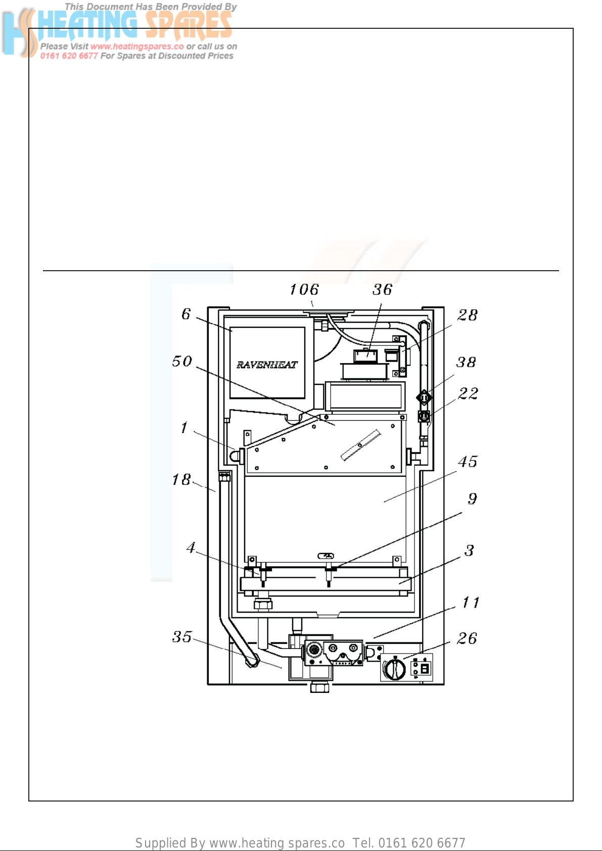
BASIC COMPONENTS - (See figure 1)
Guarantee is a full 12 months from date of purchase providing the appliance has been fitted in
accordance with these instructions and relevant codes of practice
MAJOR COMPONENTS
- Gas valve
- Burner with fl ame stabiliser designed to operate under all thermal conditions
- Primary heat exchanger constructed from copper
- Unique patented condensing heat exchanger for high thermal fl ue transfer gases to water
- Aesthetically pleasing panels and controls
- On/Off ball valve for shutting off gas
- Programmable 7 day module with digital display (optional)
NOTE: Due to the high effi ciency of this boiler a plume of water vapour will form at the fl ue terminal during operation.
COSHH - CONTROL OF SUBSTANCES HARMFUL TO HEALTH
IMPORT ANT
This appliance contains materials that are indicated below.
It is the Users/Installers responsibility to ensure that the necessary personal protective clothing is
worn when handling, where applicable, the pertinent parts that contain any materials that could be
interpreted as being injurious to health and safety .
WARNING When installing the appliance, care should be taken to avoid any possibility of injury when handling
sheet metal parts
GENERAL INFORMATION
GLUES AND SEALANTS - exercise caution - if these are still in liquid form
INSULATION PADS, CERAMIC FIBRE - may be harmful if inhaled, may be irritating to skin, eyes,
nose and throat.
When handling keep dust generation to a minimum, avoid inhaling and contact with skin or eyes .
When disposing of the product keep dust generation to a minimum and ensure that parts are securely
wrapped.
When servicing avoid inhalation by using a vacuum cleaner or in conjunction with other tools .
After handling wash hands and other exposed parts.
RAVENHEAT use only high quality material for production of this product, in an effort to protect the
environment components should be re-cycled.
3
Page 3
Supplied By www.heating spares.co Tel. 0161 620 6677
SECTIONS
TABLE OF CONTENTS
PAGE
GENERAL LAYOUT
10
11
1
2
3
4
5
6
7
8
9
INTRODUCTION
DESIGN PRINCIPLES AND
OPERATING SEQUENCE
TECNICAL DATA
GENERAL REQUIREMENTS
INSTALLATION
COMMISSIONING
SERVICING INSTRUCTIONS
FAUL FINDING
ELECTRICAL SYSTEM DIAGRAM
EXPLODED PARTS DIAGRAM
LIST OF SPARE PARTS
6
6
8-9
6
15
26
30
37
38
42
43
Fig.1
KEY
1 - Heat exchanger
3 - Burner
4 - Sensing electrode
6 - Condensing heat exchanger
9 - Ignition electrode
11- Modulating Gas Valve
15 - Heat control thermostat
18 - Frame
22 - C.H. sensor
26 -Heating control
28 - Air Pressure switch
35 - Condensing trap
4
36 - Fan
38 - Overheat cut off thermostat
45 - Combustion chamber
50 - Flue gas exhaust hood
106 - Flue restriction ring
Page 4
Supplied By www.heating spares.co Tel. 0161 620 6677
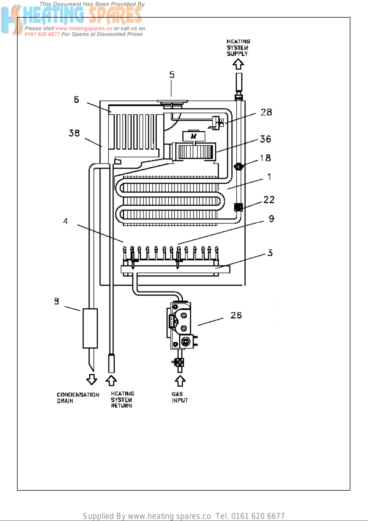
OPERATING SCHEME
KEY
1 - Heat exchanger
3 - Burner
4 - Sensing electrode
5 - Flue restriction rin
6 - Condensing heat exchanger
8 - Condensing trap
9 - Ignition electrode
18 - Overheat cut-off thermostat
22- C.H. sensor
26 - Modulating Gas Valve
Fig.2
28 - Air Pressure switch
36 - Fan
38 - Sealed chamber
5
Page 5
Supplied By www.heating spares.co Tel. 0161 620 6677
SECTION 1 INTRODUCTION
2.3.2 Air is drawn by the fan for combustion
1.1 The CSI Primary is a gas fi red room sealed
fan assisted condensing heating boiler suitable for fully pumped open vented or sealed
system central heating and domestic hot
water systems.
1.2 The provision of stored domestic hot
water is possible by the addition of
an indirect cylinder with ‘Y’ or ‘S’ plan
controls The data badge is placed on the
front panel.
1.2.1 Fig 1 illustrates the general layout of
components.
Fig.2 illustrates the operating principals
described in section 2.
SECTION 2 DESCRIPTION OF CONTROL SYSTEM
AND SEQUENCE OF OPERA TION
2.1 If the main neon is on with a demand for
heat to the system (radiators etc ) the fan
operates via the pressure switch and sends a
signal back to the ignition board that the fan
is running at maximum speed.
2.2 The spark ignition system is powered which
in turn commences the spark ignitor to
operate and light the burner. At this point
the ignition board opens the gas valve to light
the burner.
2.2.1 When the electrode/sensor senses the sig nal
of the burner the spark ignition stops.
2.2.2 From the minimum gas rate setting
the boiler increases to the maximum
permissible pressure over a period
of 3 to 4 seconds and will remain at
its maximum required power until its
maximum regulated temperature.
2.2.3 When the boiler thermostat is satisfi ed the
boiler will go to rest mode, the burner is shut
down and the pressure switch will return
back to its rest mode.
2.2.4 As the heating sensor reaches temperature
the gas burner power modulates down,
the fan speed. When starting, the fan will
always start at maximum speed.
2.2.5 The boiler is fitted with an anti-cycling
device on the control board. This delays
the boiler from re-firing over a 2/5 minute
period.
2.3 GENERAL FUNCTION
2.3.1 The gas valve boiler output settings may
be adjusted to requirements other than
factory settings
2.3.3 he fan also forces exhaust gas through the fl ue
to the outside, this creates a lesser pressure
in the sealed combustion cham ber, thus
sucking in combustion air through the inlet duct
2.3.4 The boiler water temperature is automati cally
controlled by a built in thermostat
2.3.5 Interior space temperature is set by the room
thermostat to be installed in the heat ing system The
boiler already carries con nection terminals for this
thermostat, as well as for a timeclock The burner
contin ues to operate until it is stopped by the
timer or one of the thermostats
2.3.6 When the room thermostats and/or timer intervene
the burner shuts down The fan stops and the pump
off via the pump overrun.
2.3.7 The condensate t rap is fi tted with a block age safety
sensor This prevents the boiler operating should there
be a blockage in the condensate discharge trap.
2.3.8 An overheat cut off thermostat set slightly higher
than the heat thermostat acts to turn off the burner to
resetable “lockout” (Fig 50) .
SECTION 4 GENERAL REQUIREMENTS
4.0 SAFETY
Gas Safety (Installation and Use)
Regulations, 1994 and amended 2000.
It is law that all gas appliances are installed
and serviced by a CORGI registered installer in
accordance with the above regulations and these
installation instructions. All CORGI registered
installers carry a CORGI I.D. card and have a
registration number. Both should be recorded in
your boiler log book. You can check your installer
by calling CORGI direct on: 01256 732300.
Failure to install appliances correctly could lead to
prosecution. It is in your own interest, and that of
safety, to ensure the law is complied with. Check
the boiler and flue is the correct type for installation.
The installation of the boiler MUST be in
accordance with the latest I.E.E. (BS 7671) Wiring
Regulations, local building regulations, bye-laws
of the local water authority , the building regulations
and the Building Standards (Scotland) and any
relevant requirements of the local authority.
authority, the building regulations and the Building
standards (Scotland) and any rele vant requirements
of the local authority .
4.1 GENERAL INFORMA TION
Both the user and the manufacturer rely
heavily on the installer, whose job it is to in stall the
combination boiler and connect it to a correctly
designed heating system Ac quaint yourself
with the British Standards concerning installation
requirements If you need advice on any points
your Ravenheat Technical Services Offi ce would be
pleased to help It is recommended that tools suitable
6
Page 6
Supplied By www.heating spares.co Tel. 0161 620 6677
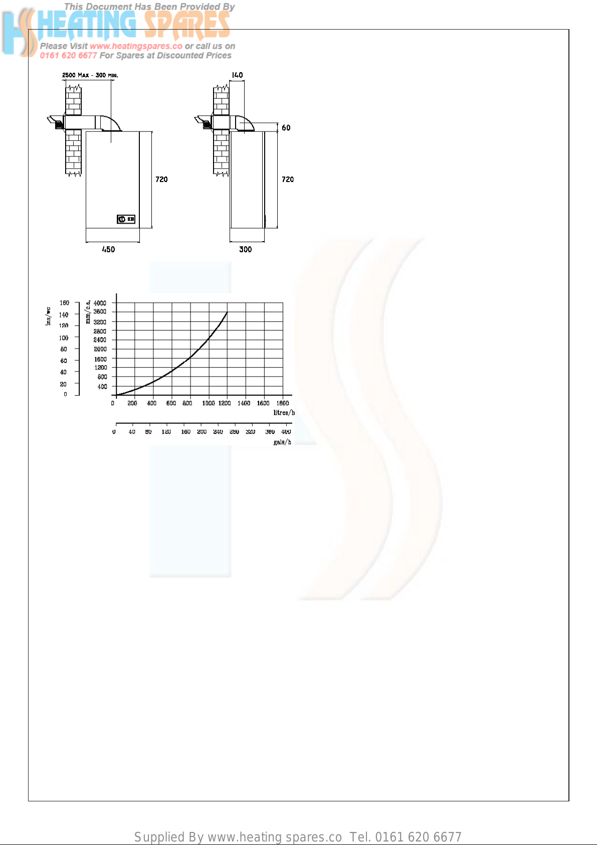
OVERALL DIMENSION
PRESSURE DROP ACROSS APPLIANCE
Fig.3
BS 5440:2 Ventilation (for gas appliances
of rated input not exceeding 60
kW)
DD 189:1990 Discharge of condensate
Health & Safety Document No. 635
The Electricity at Work Regulations1989
The manufacturer’s notes must NOT
be taken, in any way, as overriding
statutory obligations
IMPORT ANT These appliances are CE certificated for safety and performance It
is, therefore, important that no external
control devices e g flue dampers,
economisers etc , are directly connected
to this appli ance unless covered by these
Installation and Service Instructions or
as otherwise recommended by Ravenheat
in writing If in doubt please enquire
Fig.5
Any direct connection of a control device not
approved by Ravenheat could invalidate the
certifi cation and the normal appliance war-
ranty It could also infringe the Gas Safety
regulations and the above regulations
for brass fi ttings are used, and have a capa-
bility to accomodate hexagon sizes up to 50
mm.
CODES OF PRACTICE/Ref Documents
Detailed recommendations are contained in th e
following British Standard Codes of Practice
BS 6891 Low pressure installation pipes
BS 6798 Installation of gas fired
hot water boilers of rated
input not exceeding 60 kW
BS 5449 Forced circulation hot water
systems
BS 5546 Installation of gas hot
water supplies domestic
purposes (2nd Family Gases)
BS 5440 1 Flues (for gas appliances
of rated input not exceeding
60 kW)
NOTE The Ravenheat HE Primary boiler
has been tested and examined by BG,and
is certifi ed to comply with PrEN 483
Manufacturers instructions must NOT
be taken in any way as overriding
statutory obligations.
If in doubt on any point please consult
Ravenheat Manufacturing Ltd.
4.2 LOCATION OF BOILER
4.2.1 Siting of Ravenheat HE Primary Boiler
must be as follows The position of installation should be within the building, unless
otherwise protected by suitable enclosure
Adequate space for installation, servicing
and air circulation around boiler must
be allowed for.
The Ravenheat HE Primary must be fi tted
on a fl at and vertical wall capable of ade-
quately supporting the weight of the boiler
and any ancillary equipment
The appliance may be installed on a
combustible wall subject to the requirements of the Local Authority and Building
Regulations.
LPG versions of this appliance shall not
be installed in cellars or basements.
4.3 CLEARANCES AROUND THE
APPLIANCE
4.3.1 The following minimum free spaces, re-
quired for installation inspection and servicing, must be left around the boiler.
7
Page 7

Supplied By www.heating spares.co Tel. 0161 620 6677
SECTION 3 TECHNICAL DATA
HE PRIMARY AAA
TABLE 1
NATURAL GAS (G 20) І2H - П2H3+
NOMINAL HEAT INPUT NET QMS 22.6 kW
MINIMUM HEAT INPUT NET 11.6 kW
NOMINAL HEAT OUTPUT 22.3 kW
MINIMUN HEAT OUTPUT CONDENSING 23.9 kW
NOMINAL HEAT OUTPUT 11.4 kW
MINIMUM HEAT OUTPUT CONDENSING 12.3 kW
GAS RATE Max 2.3 m
3
/h
AFTER 10 MINUTES min 1.2 m3/h
INLET PRESSURE 20 mbar
BURNER PRESSURE max 10.5 mbar
min 2.0 mbar
BURNER INJECTORS Nr. 13 x 1.25
ELECTRICAL SUPPLY 230V ~ 50 Hz
POWER CONSUMPTION 60 W
EXTERNAL FUSE RATING 3 A
INTERNAL FUSE 2 A
DRY WEIGHT 35 kg
WATER CONTENT C H 0.5 litre
GAS SUPPLY CONNECTION C H 15 mm
FLOW CONNECTION C H 22 mm
RETURN CONNECTION C H 22 mm
CONDENSATION DRAIN 3/4” (21.5 mm) push fi t over fl ow
SEALED WATER SYSTEM C.H.
MAX PRESSURE PMS 2.5 bar
MINIMUM WORKING PRESSURE 0.5 bar
CENTRAL HEATING OPERATING TEMPERATURE MAX - 85 °C min - Off
FLUE OUTLET NOM. DIAMETER 60/100 mm specially supplied with boilers
DESTINATION : AT, DK, Fl, SE CATEGORY I
DESTINATION: GB, IE, CH, ES, IT, PT CATEGORY II2H3+
FLUE TYPE: C12 - C32 - C52 NOX 4
8
2H
Page 8
Supplied By www.heating spares.co Tel. 0161 620 6677
HE PRIMARY AAA
TABLE 1/A
LPG (G 30 - G 31) І3p - П2H3+
NOMINAL HEAT INPUT NET QMS 22.6 kW
MINIMUM HEAT INPUT NET 11.6 kW
NOMINAL HEAT OUTPUT 22.3 kW
MINIMUN HEAT OUTPUT CONDENSING 23.9 kW
NOMINAL HEAT OUTPUT 11.4 kW
MINIMUM HEAT OUTPUT CONDENSING 12.3 kW
GAS RATE Max G31 0.9 m
3
/h G30 0.7 m3/h
AFTER 10 MINUTES min 0.4 m3/h 0.3 m3/h
INLET PRESSURE G31 37 mbar G 30 28-30 mbar
BURNER PRESSURE Max G 31 35. 4 mbar G 30 27. 3 mbar
min 7. 3 mbar 7. 0 mbar
BURNER INJECTORS Nr. 13 x 0.75
ELECTRICAL SUPPLY 230V ~ 50 Hz
POWER CONSUMPTION 60 W
EXTERNAL FUSE RATING 3 A
INTERNAL FUSE 2 A
DRY WEIGHT 35 kg
WATER CONTENT C H 0.5 litre
GAS SUPPLY CONNECTION C H 15 mm
FLOW CONNECTION C H 22 mm
RETURN CONNECTION C H 22 mm
CONDENSATION DRAIN 3/4” (21.5 mm) push fi t over fl ow
SEALED WATER SYSTEM C. H.
MAX PRESSURE PMS 2. 5 bar
MINIMUM WORKING PRESSURE 0. 5 bar
CENTRAL HEATING OPERATING TEMPERATURE MAX - 85 °C min - Off
FLUE OUTLET NOM. DIAMETER 60/100 mm specially supplied with boilers
DESTINATION : BE, FR CATEGORY I
DESTINATION : GB, IE, CH, ES, IT, PT CATEGORY II2H3+
FLUE TYPE : C12 - C32 - C52 NOX 4
3p
9
Page 9
Supplied By www.heating spares.co Tel. 0161 620 6677
18 inches (450 mm) in front
5 inches (125 mm) above
6 inches (150 mm) below
0 2 inches (5 mm) on each side
1 inch (25 mm) in front when installed in
a cupboard
4.4 IMPORTANT NOTICE
4.4.1 If the boiler is to be fi tted in a timber
framed building it should be fitted
in accordance with the British Gas
Publication Guide for Gas Installations
in Timber Frame Housing Reference
DM2. If in doubt advice must be
sought from the local gas supplier
The boiler may be installed in any room
or internal space, although particular
attention is drawn to the requirements of
the current I.E.E Wiring Regulations, and
in Scotland the electrical provisions
the Building Regulations applicable in
Scotland, with respect to the installation
of the combina tion boiler in a room or
internal space con taining a bath or shower
Where a room sealed appliance is
installed in a room containing a bath or
shower, any electrical switch or appliance
control, utilis ing mains electricity should
be so situated that it cannot be touched by
a person using a bath or shower.
A compartment used to enclose the boiler
MUST be designed and constructed specifically for this purpose an existing cupboard,
or compartment, may be used provided it
is modified accordingly. Samples of the
CSI boiler have been examined by BG
Technol ogy Notifi ed Body, and is certifi ed
to comply with the essential requirements
of the Gas Appliance Directive 90/396/
EEC, the Low Voltage Directive 72/23/
EEC and shows compliance with the
Electra Magnetic Com patibility Directive
89/336/EEC and are therefore permitted
to carry the CE Mark .
The appliance has been tested and
approved by the WRc as meeting
the requirements of G3 and L of the
Building regulations and water Bylaws
Scheme- Approved Products.
4.5 GAS SUPPLY
4.5.1 A gas meter is connected to the
service pipe by the Local Gas Region
or the Local Gas Region contractor
An existing meter should be checked
preferably by the Gas Region to ensure
that the meter is ade quate to deal with
the rate of gas supply required for all
appliances it serves Instal lation pipes
should be fi tted in accordance with BS
6891 Pipework from the meter to the boiler
must be of adequate size (22 mm) min To
within at least 3 metre of the boiler (15
mm) min can then be used for remain ing
pipe work to the appliance.
of-
A smaller size than the boiler inlet
gas connection should not be used The
complete installation must be tested for
soundness as described in the above Code
N B: if the gas supply for the boiler serves
other appliances ensure an adequate
sup ply is available both to the boiler and the
other appliances when they are in use at
the same time.
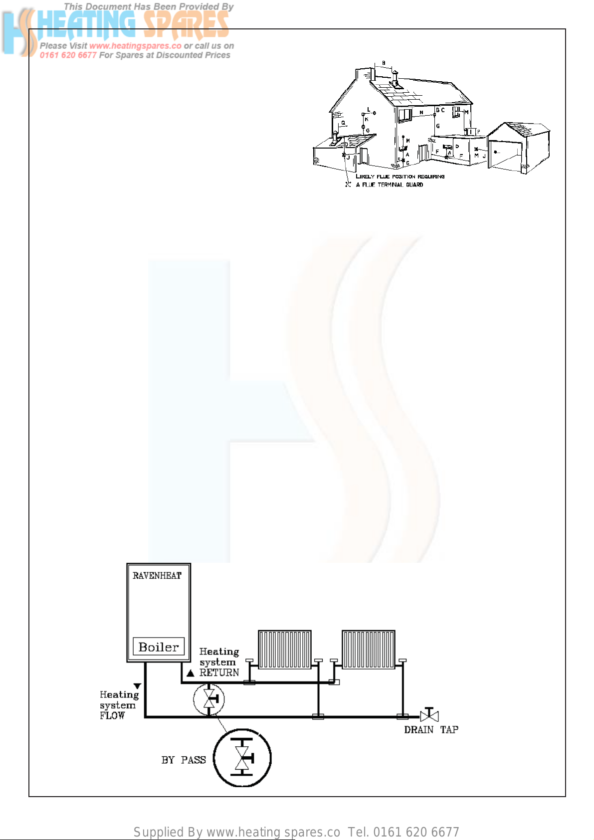
4.6 FLUE SYSTEM
4.4.1 The terminal should be located where dis-
persal of combustion products is not impeded and with due regard for the damage or
discolouration that might occur to building
products in the vicinity (see fi g 6) The terminal
must not be located in a place where it is
likely to cause a nuisance In cold and/or
humid weather water vapour may condense
on leaving the fl ue terminal The effect of such
steaming must be con sidered.
The terminal must not be closer than 25 mm (1
in) to any combustible material For protection
of combustibles, refer to BS 5440.1.
Where a fl ue terminal is installed less than
1000 mm from a plastic, or painted gutter, or
500 mm from painted eaves, an alumini um
shield 1000 mm long, should be fi tted to the
underside of the gutter or painted surface
Pluming will occur at the terminal so, where
possible, terminal positions which could
cause a nuisance should be avoided The
fl ue must be installed in accordance with the
recommendations of BS 5440.Part 1.
IMPORTANT NOTES
For greater fl ue lengths see twin fl ue
Instructions.
Flue must be positioned in a place not likely
to cause a nuisance.
IMPORT ANT: The following notes are intended
for general guidance.
The boiler MUST be installed so that the
terminal is exposed to external air.
It is important that the position of the termi nal
allows the free passage of air across it at all
times.
Minimum acceptable spacing from the ter-
minal to obstructions and ventilation open ing
are specifi ed in Fig.6
Note positions: Due to the terminal design,
installation is possible with clearances less
than those specifi ed in BS 5440, Part .1.
10
Page 10
Supplied By www.heating spares.co Tel. 0161 620 6677
NOTE The fl ue must be terminated in a place not
likely to cause a nuisance
4.6.2 A concentric vertical fl ue kit is available, for
fl ueing applications up to a maximun height
of 40 metres.
For further details see vertical fl ue installation
instructions.
4.7 AIR SUPPLY
4.7.1 The following notes are intended for general
guidance.
The room sealed fan fl ued boiler does not re
quire a permanent air vent for combustion air
supply.
Where installed in a cupboard or compartment
ventilation is not required.
CONDENSATE DRAIN
A condensate drain is provided on the boiler
This drain must be connected to a drainage
point All pipework and fi ttings in the condesate
drainage system MUST be made of plastic-no
other materials may be used Discharge of
condensate DD X 189 1990 Y.
The drain outlet on the boiler is standard
3/4” (21 5 mm) push fi t overfl ow pipe.
NOTE:Condensate drain pipework must
never be less than 15 mm.
Important: any external runs must be carried
out in 1 1/4 (32 mm) wastepipe .
A fall of 2 5° (45 mm/m) all runs must have.
4.8 WATER CIRCULATION (central heating)
4.81 Detailed recommendations are given in BS
6798:1897/ 5449 : 1990 (for smallbore
and microbore central heating systems).
The following notes are given for general
guidance.
Fig 6
Terminal position for fan assisted boiler
(minimum distance) mm
A- Directly below an open window or other 300
opening (e.g. air brick)
B - Below gutters, soil pipes or drain pipes 75
C - Below eaves 150
D - Below balconies or car port roof 200
E - From vertical drain pipes and soil pipes 150
F - From internal or external corners 300
G - Above ground or below balcony level 300
H - From a surface facing a terminal 600
I - From a terminal facing a terminal 1200
J - From an opening in the car port
(e.g. door window) into dwelling. 1200
K - Vertically from a terminal on the same wall 1500
L - Horizontally from a terminal on the same wall 300
M - From adjacent wall to flue 300
4.8.2 Pipework
Copper tubing to BS 2871 1.1.1971 is reco mended for water pipes Jointing should be
either with capillary soldered or with
compression fi ttings.
Where possible pipes should have a gradient
to ensure air is carried naturally to air release
points and water fl ows naturally to drain taps,
It should be ensured as far as possible that
the appliance heat exchanger is not a natural
collecting point for air.
Except where providing useful heat, pipes
should be insulated to prevent heat loss and
to avoid freezing Particular attention should
be paid to pipes passing through ventilated
spaces in roofs and under fl oors.
Fig.6A
11
Page 11

Supplied By www.heating spares.co Tel. 0161 620 6677
WATER SYSTEM
4.8.2.1 WATER SYSTEM
For an open (vented) system the boiler
must be supplied from an unrestricted
water supply taken from a feed and expan sion tank (minimum 22 litre 5 gall)
capacity situated at a maximum
height of 27 5 metre (90ft) above
the boiler The cold feed supply must
be 15 mm minimum size It is impor tant that the relative positions of the
pump, cold feed and open vent See Fig
6D
4.8.2.2 CILINDER
The hot water cylinder must be a
double feed (fully indirect) type
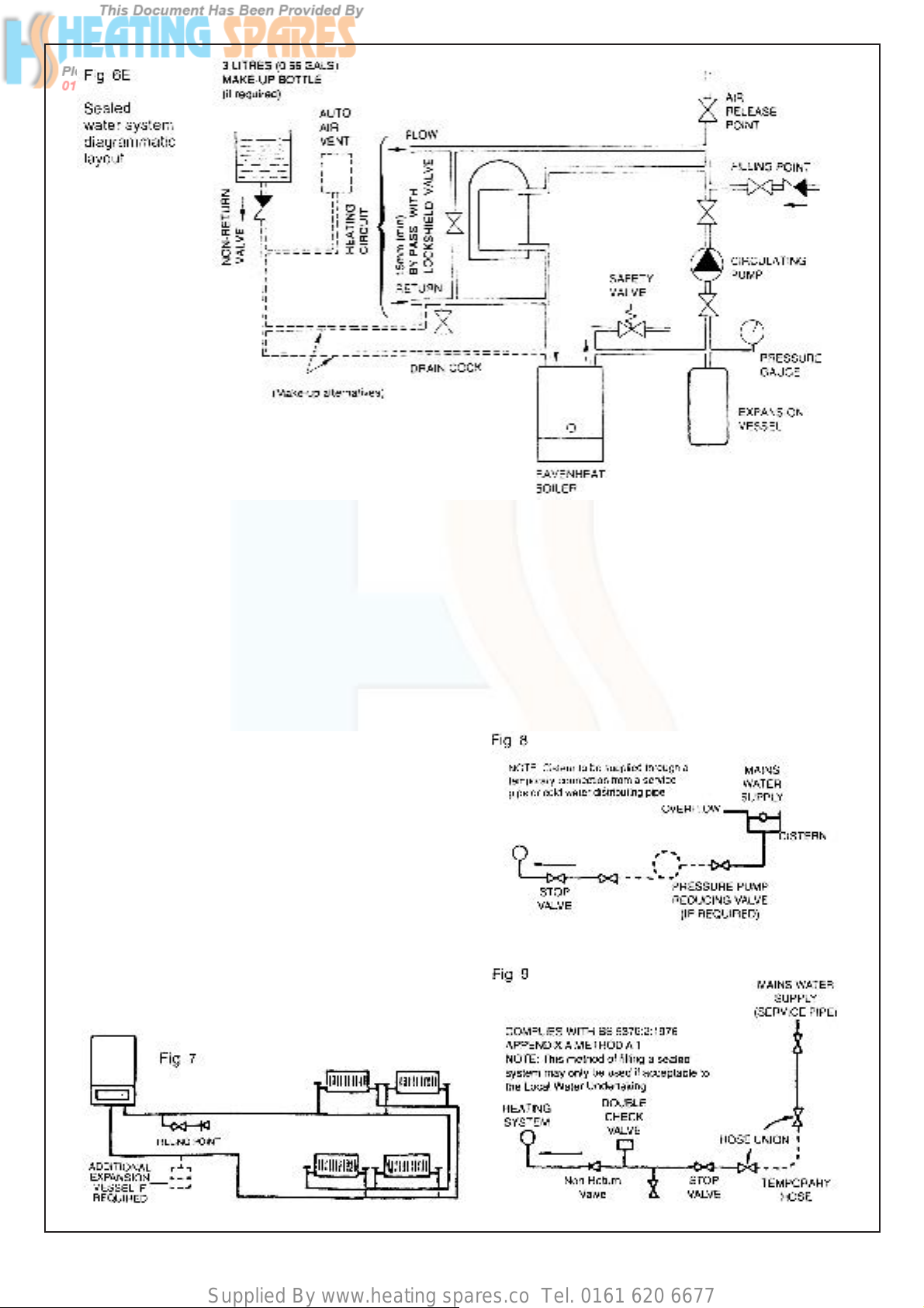
4.8.2.3 SEALED W ATER SYSTEMS
The installation should comply with
the appropriate requirements of BS5449
Part 1 and BS6798, see Fig 6E All valves
and fi t tings must be suitable for use on
sealed systems
4.8.2.4 SAFETY V ALVE
The safety valve must be fi tted in a sealed
system The safety valve must conform
to BS6759 Part 1 and be fitted to the
require ments of BS6798
4.8.2.5 EXP ANSION VESSEL
A diaphragm type expansion vessel,
con forming to BS4814 must be connected
at a point close to the inlet side of the
circulating pump, see Fig 6E or as laid
down by the manufacturer
The expansion vessel must suit the volume
of water in the system, s ee BS5449 Part 1
clause 25 for details The charge pressure
must not be less than static head i e
the height of the highest point of the
system ABOVE the expansion vessel
The expansion vessel should have
suffi cient capacity to accept the volume
change when the water is heated from 10
°C to 110 °C Refer to BS5449 Part 1
for specific details See Table 3
4.8.2.6 PRESSURE GAUGE
A pressure gauge with set pointer and cov-
ering at least the range 0 to 4 bar (0 to 60
2
) shall be permanently fi tted to the sys-
lb/in
tem in a position it can be seen when carry ing out the fi lling operation
4.8.2.7 SYSTEM DESIGN
Fig 6A illustrates typical heating only lay -
out Figs 6B and 6C illustrate typical layout
with ‘Y’ or ‘S’ plan system
4.8.3 The water through the appliance heat
exchanger circuit must exceed the min 1 84
gals min (503 It/h) when the burner is fi ring
It is important to ensure that this rate is
achieved when sections of the system are
shut off either manually or bu automatic
12
Page 12
Supplied By www.heating spares.co Tel. 0161 620 6677
controls Therefore a by-pass must be fi t-
ted to the system (15 mm min) (Fig. 6A).
If the volume of circulating water is too low,
the boiler water temperature will rise too
rapidly This could cause noise in the system
or evene cause the safety thermostat to trip
4.8.4. Draining tap
These must be located in accessible posi-
tions to permit the draining of the
whole system The taps must be at least
15 mm nominal size and manufactured
in accor dance with BS 2870 1980.
4.8.5 Air release points
These must be fi tted at all high points where
air will naturally collect, and must be sited to
facilitate complete fi tting of the system.
4.8.7 Mains water feed: central heating
There must be no direct connection to
the mains water supply, even through a
non- return valve, without the approval
of the Local Water Authority.
4.8.8 Permissible methods of fi lling
Cistern method (Fig 8)
The system may be fi lled by one of the fol-
lowing methods Through a cistern used for
no other purpose, via a ballvalve perma nently connected directly to a service
pipe and/or cold water distributing pipe .
The sta tic head available from the
cistern should be adequate to provide
the initial system design pressure.
The cold feed pipe from the cistern should
include a non-return valve, and a stop-valve
with an automatic air vent connected be tween them, with the stop valve being locat ed, between the cistern and the automatic
air vent The stop valve may remain open
during normal operation of the system,
if automatic water make-up is required
Booster pump method (Fig 8).
13
Page 13
Supplied By www.heating spares.co Tel. 0161 620 6677
SIZING OF EXPANSION VESSEL TABLE 3
Safety
valve setting (bar)
Vessel charge
pressure (bar)
Initial system
pressure (bar)
T otal water
content of system
Litres
25
50
75
100
125
150
175
200
225
250
275
300
325
350
375
400
425
450
475
500
30
05 10 15
05 10 15 20 10 15 20 15 20
EXPANSION VESSEL VOLUME (LITRES)
21
42
63
83
104
125
146
167
187
208
229
250
270
291
31 2
333
354
375
396
41 6
35
70
105
140
175
210
245
280
31 5
350
385
420
455
490
525
560
595
630
665
700
65
129
194
259
324
388
453
51 8
583
647
71 2
777
841
906
97 1
1036
1101
1165
1230
1259
137
275
413
551
689
826
964
1102
1240
1377
151 5
1653
179 1
1928
2066
2204
2392
2479
261 7
2755
27
54
82
109
136
163
191
218
245
272
300
327
357
38 1
409
436
463
490
51 8
545
47
95
142
190
237
285
332
380
427
475
52.2
570
61 7
665
71 2
760
807
855
902
950
103
206
309
412
515
618
721
824
927
1030
11
33
1236
1339
1442
1545
1648
1751
1854
1957
2060
39
78
117
156
195
234
27 3
312
35 1
390
429
468
507
546
585
624
663
702
741
780
83
165
248
331
413
496
579
662
745
827
910
993
1076
1158
1241
1324
1407
1489
1572
1655
For system volumes
other than those given
above, multiply the
system volume by
the factor across
Note: This pressure can be increased up to 1.5 bar to suit high static head situations, see item 10, other appliance components in the
SERVICING INSTRUCTIONS
The system may be fi lled through a self
contained unit comprising of a cistern pressure booster pump if required and if necessary an automatic pressure reducing valve
or fl ow restrictor The cistern should be sup-
plied through a temporary connection from
a service pipe or cold water distributing
pipe The unit may remain permanently connected to the heating system to provide limited automatic water make up
Mains topping up method (Fig 9)
00833
0 1 40 0 259 0 55 1 0 109 0 1 9 0 0 412 0 15 6 0 331
hose from the draw off tap shall be con-
nected to this fi tting)
b) A test clock
c) Double check valve of an accepted
type
d) A non return valve of an accepted
type
We recommend use of a Ravenheat
Filling Loop designed for this
method of fi lling the system A vailable
from your supplier
Here the temporary connection is supplied
from a service pipe, or distributing pipe,
which also supplies other draw-off points at
a lower level
A combined double check valve shall be
installed upstream of the draw-off point,
through a temporary hose connection from
a tap supplied from the mains, where the
mains pressure is excessive a pressure
reducing valve shall be used to make fi lling
easier The following fi ttings shall form a
permanent part of the system and shall be
fi tted in the order stated
a) A stop valve complying with the require
ments of BS 1010 Part 2 (the temporary
PROVISIONS FOR MAKE UP WATER
(Fig 7)
Provision can be made for replacing water
loss from the system either
A) from a manually fi lled made up bottle
with a readily visible water level The bottle
should be mounted at least 150 mm (6 in)
above the highest point of the system and
be connected through a non return valve
to the return side of the heating system
B) Where fi tting a make up vessel would
be diffi cult re pressurisation of the system
can be done See section on FILLING
If the capacity of the central heating system
14
Page 14
Supplied By www.heating spares.co Tel. 0161 620 6677
should exceed 110 litres, an additional
ves sel should be installed on the return
to the combination boiler from the heating
system (Fig 7) Guidance on vessel sizing
is given in (Table 3).
Reference should be made to British
Gas Publications «Material and
Installation Specifi cations for Domestic
Central Heating and Hot Water» Draining
taps should be at least 1/2” in BSP
nominal size and be in accordance with
BS 2879.
4.8.9 Installation to an existing central heating
system
Before installing a new boiler to an existing
system, fl ush out the old system with a rec-
ommended descaling agent.
It is most important that the correct concentration of the water treatment product
is maintained in accordance with the
manu facturers’ instructions .
If the boiler is installed in an existing system
any unsuitable additives MUST be removed
by thorough cleansing BS 7593 1992
details the steps necessary to clean
domestic central heating system Also
check pipework and renew any corrod ed
pipework or fittings V alve glands must be
repacked or replaced wherever necessary and any defective controls exchanged.
WATER TREATMENT
This boiler has a secondary
ALUMINIUM alloy heat exchanger.
Ravenheat recom mended only the
use of FERNOX-COPAL SENTINEL
X100 or SALAMANDER CUR ROSION
GUARD water treatment products,
which must be used in accordance
with the manufacturers instructions
For further information contact
Fernox Manufacturing Co Ltd
Tel 01799 550811
Sentinel Division Betz Dearborn Ltd
Tel (0151) 424 5351
Salamander (Eng)Ltd
Tel (0121) 3780952/4508
4.10 ELECTRICAL SUPPLY
Warning: this appliance must be
earthed
4.10.1 External wiring to the appliance
must be carried out by a competent
person and be in accordance with the
current I.E.E. Regula tions and local
regulations which apply The Ravenheat
boiler is supplied for con nection
to a 230 V ~ 50 Hz single phase
supply The supply must be fused at 3 A.
NOTE The method of connection
to the electricity supply MUST
facilitate complete electrical isolation
of the appliance, by the use of a fused,
double pole isolator, having a contact
separation of at least 3 mm in all poles
The point of connection to the elec tricity
supply must be readily accessible and
adjacent to the appliance except,
where the appliance is installed
in a bathroom, this MUST be sited
outside the bathroom
SECTION 5 INSTALLATION
5.1 WARNING
5.1.1 It is MOST IMPORTANT that this
appliance is installed in a VERTICAL
POSITION, with the fl ue air duct
passing through the wall Make sure
fl ue slopes 2.5° down towards
the boiler that is 45 mm/m fall per
metre of fl ue length.
15
Page 15
Supplied By www.heating spares.co Tel. 0161 620 6677
5.2 DELIVERY
5.2.1 The appliance carton containing (Fig.15)
a) boiler fully assembled
b) installation instructions and
user instructions
c) white paper template
d) terminal cover plate
Polythene bag containing
a) 1-1/2” BSP Union Gas Cock
b) 2-22 mm fl anged copper tails complete
with 3/4” brass nuts and washers
c) 4 coach bolts and wall plugs
screws and dowels.
WARNING
Maximum allowable fl ue length 2.5 m
maximum No 2x1000 mm
Flue duct extension used with standard fl ue
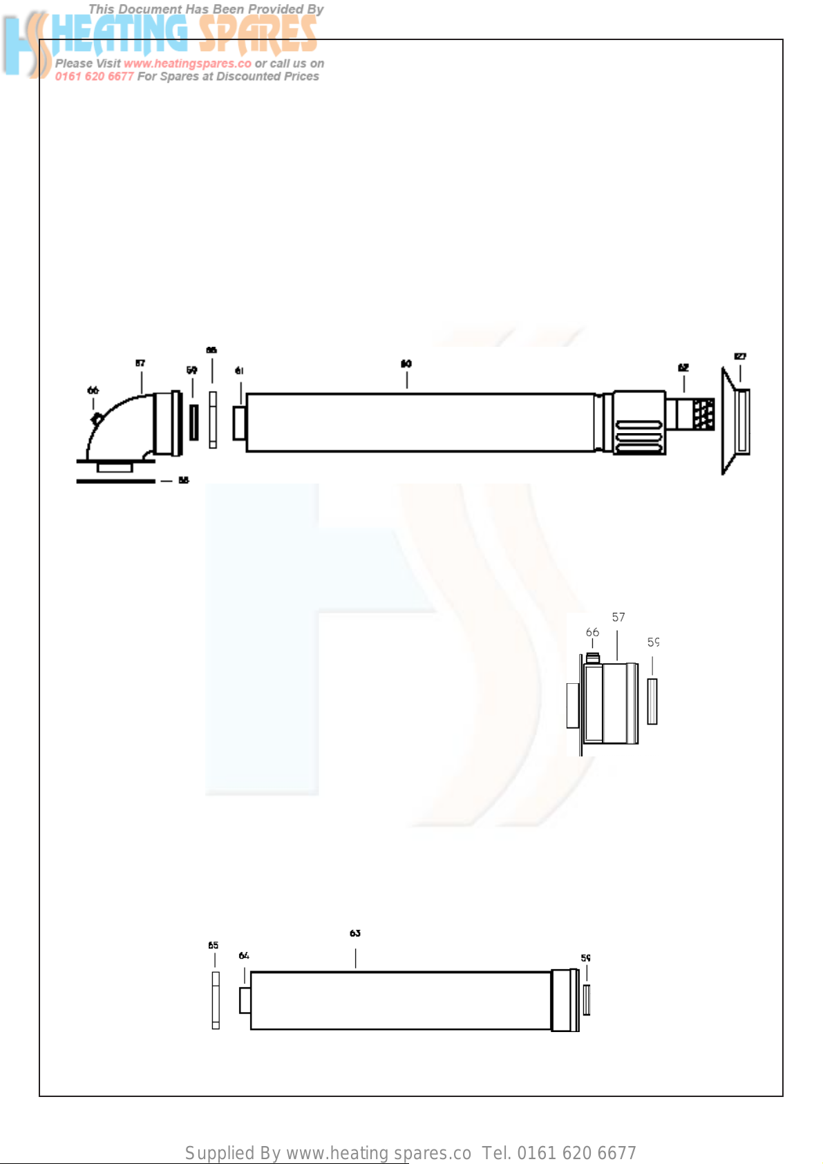
Horizontal HE fl ue kit carton
containing (Optional) (Fig 12)
57- Flue bend assembly
58- Header gasket
59- Rubber seal Ø 60
60- Air intake duct
61- Flue exhaust duct
62- Terminal
65- Pipe centering spring
66- Flue gas sample point
127-Terminal Cover Plate
Fig. 12
OPTIONAL EXTRAS:
STRAIGHT HEADER Box containing (Fig 13) :
57 - Straight header
59 - Rubber seal Ø 60
66 - Flue gas sample point
FLUE EXTENSION Box containing(Fig 14)
1000 mm fl ue extension duct as an extra cost only when
requested for side and vertical fl ue applications
59 - Rubber seal Ø 60
63 - Air intake duct extension
64 - Flue exhaust duct extension
65 - Pipe centering spring
Fig. 13
Fig. 14
16
Page 16

Supplied By www.heating spares.co Tel. 0161 620 6677
Fig. 18
17
Page 17

Supplied By www.heating spares.co Tel. 0161 620 6677
5.4 POSITIONING OF THE BOILER
5.41 Remove the 4 screws that secure the upper
and the lower part of the casing(Fig.19-20).
5.4.2 Unscrew the 4 screws that fasten the lower
grating on the casing and remove it from the
sides of the casing (Fig.20)
5.4.2.1 Carefully slide the casing forward to lift off.
(Fig 21).
5.4.2.2 Make sure that the casing and screws are put
to one side in a safe place.
5.4.3 Lifting instrument panel (not necessary
for installation).
- Unscrew the 2 screws that fasten the
instrument panel.
- Lift the instrument panel in order to
deta ch it from the sides, and lift it up
by rotating it on its own hinges.
Make sure the casing screws are put to
one side in a safe place.
Fig. 19
Fig. 20
Fig. 21
5.5 INST ALLING THE APPLIANCE FOR
REAR FLUE OUTLET
5.5.1 Use adhesive tape to attach the template to the
wall, making sure that the centre line is vertical
- Mark the four boiler fastening holes on the
wall as well as the centre of the fl ue duct
- Detach the template from the wall.
- Use a 10 mm dia drill to make the 4 boi ler
securing holes Insert the plastic expansion
plugs.
- Cut or core drill a 105 mm dia hole for
inserting the fl ue duct
- Screw in the two upper coach bolts leaving
them about 10 mm out from the wall to
enable the boiler to be located on the wall .
Fit the elbow header positioning it towards
the required direction (Fig 30).
IMPORTANT: Make sure that the elbow’s dia 60 mm
duct is inserted into the fan, the rubber seal and orifi ce
(F2) have been cor rectly fi tted.
Fig. 28
18
Page 18

Supplied By www.heating spares.co Tel. 0161 620 6677
5.5.2 Locate the rubber Ø 100 and Ø 60 into the fl ue
elbow header (Fig 30).
IMPORTANT
CORRECT FLUE MUST BE USED .
Check Spigot Distance ( approx 35mm )
on STARTER HEADER.
Ensure Flue is fi tted together correctly,
supported and fi rmly secured . (Fig.29).
Fig. 29
Fig. 30
- Cut the inner fl ue duct (60 mm) at right
- angles to a length equal to W + 264 mm
Insert from cut end Reassemble the
two tubes Insert centering spring 65 Must
be de-burred
- Reassemble together inner and outer fl ue
duct insert centering spring.
Fig. 32
INTAKE AND EXHAUST TERMINAL COMPONENTS
Fig. 31
KEY
56 - Straight header
57 - Elbow header
58 - Header gasket
59 - Rubber seal Ø 60
60 - STD air intake duct
61 - STD fl ue exhaust duct
62 -Terminal
63 - air intake duct extension
64 - Flue exhaust duct extension
65 - Pipe centering spring
66 - Sample point
127 - Terminal cover plate
19
Page 19

Supplied By www.heating spares.co Tel. 0161 620 6677
5.5.3 If the standard duct furnished with the boiler
is too long (the wall to go through is less than
680 mm thick) it can be shortened as follows
- Remove the centering spring 65, the fl ue
terminal to disengage inner fl ue duct
- Measure the thickness W of the wall
- Cut the outer fl ue duct at right angles to a
length equal to W + 152 mm
Must be de-burred.
5.5.4 Insert the fl ue assembly into the wall, being
careful to make sure that the outer air duct
comes fl ush to the inner surface of the wall.
5.5.5 Lift the boiler on to the wall (Fig 34), locating
onto the top coach bolts Fit the two lower
coach bolts and tighten all four securing
bolts.
5.5.6 Working above the boiler pull the fl ue exhaust
duct towards the boiler in order to engage
tube item 61 into its header 57 ( Fig.31).
Position fl ue into elbow header and push so
as to locate inner and outer fl ue correctly
ensuring good seal is made with o-rings.
5.5.7 Fit terminal cover plate and terminal guard.
(Fig.37)
Fig.35
Fig 36
5.5.8 Extension kits are available on order for fl ue
extension of up to 2.5 metres total length
(Fig.31).
Fig 37
20
Page 20

Supplied By www.heating spares.co Tel. 0161 620 6677
5.5.9 Each extension length extends the pipe by
approximately 1000 mm long up to a maxi mum
of two extensions.
Pipeline length can be established using the
instructions in section 5.5 for rear fl ue outlets
and section 5.7 for side fl ue outlets. Extensions
must be installed with the widened end of the air
intake pipe and the tapered end of the fl ue pipe
aimed towards the exhaust terminal. Extensions
must be joined together with the standard
terminal pipe, and inserted in each other as far
as they can go.
If an extension must be shortened, this must
be done from the straight end, and not from the
widened or tapered end .T o mea sure the pipeline
properly all components must be assembled
and total length mea sured before cutting. The
straight end of the extension connects to the
boiler. The fl ue output pipe fi ts into the boiler
header until it stops .The air intake pipe should
be located approximately 2 mm from the boiler
header (Fig 31).
When cutting both inner and outer ducts of the
extension, always ensure that the reduced end
(male) of the inner duct is longer than the outer
duct.
All joints must be sealed with the rubber seals
supplied.
It is important to put the centering spacer,
supplied with the unit, inside between the two
pipes, from the side opposite the exten sion’s
straight end.
5.7 INSTALLING THE APPLIANCE FOR SIDE
FLUE OUTLET (Fig. 28)
5.7.1 - Attach the template to the wall with adhe-
sive tape, making sure that the centre line
is vertical and that the distance from the
centre line to the nearest side wall is not
less than measurement in table 6.
- Mark the four boiler securing holes on the
wall and extend the axis of the fl ue duct
hole to the side wall ensuring it is
horizontal.
- Trace the centre of the fl ue duct hole
measure distance F (table 6) From the
corner of the wall (Fig. 28), measure the
distance Y between the centre of fl ue duct
hole to the corner Detach the template
from wall.
- Use a dia 10 mm drill to make the 4 holes
for securing the boiler Insert the plastic
expansion plugs Core drill a 105 mm dia
hole in the side wall for inserting the fl ue
duct.
TABLE 6
CSI PRIMARY
F = 140 mm
G = 275 mm
NOTE: A suitable support bracket is availa ble
from Ravenheat Manufacturing and should
be used to support fl ue length at least every
1.8 metre preferably at each joint this bracket
should be secured to wall and fl ue duct.
5.5.10 INLINE FLUE BEND
Measure the distance between the fl ue bends or
the fl ue/terminal assembly . The measurements
should be taken from the outer edge of the fl ue
and bend(Fig.39). IMPORT ANT: Inline fl ue
bend - 1680 mm must be deducted from
overall length for each 90° bend - 1680 mm
must be deducted from overall length for
each 135° bend (Fig 39).
5.6 COMPLETING BOILER INSTALLATION
5.6.1 Reassemble the outer casing (sect 5 4)
proceeding in this order
1) Fit the two sides
2) Refi t the instrument panel in reverse ord er
as in sect. 5.4.3.
3) Refi t the lower grating .
21
Page 21

Supplied By www.heating spares.co Tel. 0161 620 6677
Fig.39
IN LINE FLUE BEND AND FLUE EXTENSION
KEY
56 - Sample point
57 - Elbow Header
59 - Rubber seal Ø 60mm
5.7.2 Positioning the elbow towards the required direction
(Fig 30).
5.7.3 Locate the rubber Ø 60 into the elbow.
(Fig 30) .
5.7.4 - If the standard duct furnished with the
boiler is too long (position of the boiler
from the wall to go through as illustrated
in the drawing and wall thicknesses less
than what was specified above) it can be
shortened as follows (Fig 28-29-31-32)
Cut or core drill a 105 mm dia hole for
inserting the fl ue duct.
- Remove the centering spring 65 (Fig39),
pull the fl ue terminal disengage inner fl ue
duct.
- Measure the thickness W of the wall
- Cut the outer air duct (100 mm dia) at
right angles and to a length equal to
W +Y - 47 mm (Fig. 32).
- Cut the inner fl ue duct (dia 60 mm) at
right angles and to a length equal to
W +Y + 65 mm .
- Outer air duct and inner fl ue duct must be
de-burred.
- Reassemble the two tubes, insert
centering spring 65. (Fig.39).
63 - Air intake duct extension
64 - Flue Exhaust duct extension
65 - Pipe centering spring
128 - In Line Bend
5.7.5 Insert the fl ue assembly into the wall, making
sure it will not interfere when fi xing the boiler on
the wall.
5.7.6 Lift the boiler on the wall.
Locate onto the top coach bolts.Fit the lower
coach bolts and tighten all four securing bolts.
5.7.7 Working above the boiler pull the fl ue duct
towards the elbow in order to engage tube into
its header (Fig.35).
Position fl ue into straight header and push
so as to locate inner and outer fl ue correctly.
Ensuring good seal is made with o rings.
5.7.8 IMPORTANT: Terminal rubber must be
fi tted (Fig 36-37).
5.7.9 Extension kits are available on order for
fl ue extension of up to 2.5 metres total
length (Fig.31) For further details see
sect. 5.5.9.
5.7.10 VERTICAL FLUE INSTRUCTIONS ONLY
L
L
Fig.40-P Fig.40-M
22
L
Fig.40
L
L+ L = 3.25m MAX
Page 22

Supplied By www.heating spares.co Tel. 0161 620 6677
INLINE FLUE BEND - 1680 mm MUST BE DEDUCTED FROM OVERALL LENGTH FOR EACH 90° BEND OBTUSE
FLUE BEND - 1680mm MUST BE DEDUCTED FROM OVERALL LENGTH FOR EACH 135° BEND
The vertical fl ue kit is intended
for use where a horizontal fl ue
outlet is not possible or desired The vertical fl ue can be
used either with a fl at roof or
a pitched roof (maximum pitch
60°) Where a straight vertical
fl ue is not possible or desired, an offset vertical fl ue can
be used in conjunction with a
side horizontal fl ue extension
piece and an inline 135°/90°
fl ue bend (Fig 41)
IMPORTANT NOTES
For greater fl ue lengths see
twin fl ue leafl et
L
L = 3.0m MAX
plus Vertical Flue kit
Fig 41
LL
L = 3.0m MAX
plus Vertical Flue kit
L = 2.25m MAX
(2 in line 45° bend Max)
plus Vertical Flue kit
Proceed with installation as detailed in section 5 up to
5.4. 8 , of the main Installation and Servicing Instruction,
ignoring all references to horizontal fl ue installations
Fig 42
POSITION MIN DISTANCE mm
N above roof level (to base of terminal) 300
P from adjacent wall to fl ue 300
Q from internal corner to fl ue 300
S from facing terminal 1,200
M horizontally from a vertical terminal to a wall 300
Before proceeding with installation check the contents of
the RAVENHEAT VERTICAL FLUE KIT, comprising
of the following pieces
- 1 RAVENHEAT VERTICAL FLUE complete
with terminal assembly (for vertical fl ue application).
- Additional 1000 mm (approx) .
Flue Extension pieces as necessary,
each extension is provided with inlet and outlet
sealing rings and fl ue centering bracket
- One box containing straight header with
inlet and outlet sealing rings.
Use adhesive tape to attach the template to the wall,
making sure that the centre line is vertical and that the
fl ue centre line is virtually below the point at which the
fl ue will exit the roof.
- Ensure that the maximum permissible fl ue
length is not exceeded (Fig .42).
- Mark the four boiler fastening holes on the
wall.
- Detach the template from the wall.
- Use a 10 mm dia drill to make the 4 boiler
securing holes.Insert plastic expansion
plugs (Fig 29).
- Screw in the two upper coach bolts leaving
them about 10 mm out from the wall to
enable the boiler to be located on the wall.
- Position the straight header on the top of
the appliance (Fig 43) Item 6, and ensure
that the gasket and sealing rings are cor
rectly fi tted.
IMPORTANT: Make sure that the fl ue header
dia 60 mm duct is inserted fully into the fan spigot.
23
Page 23

Supplied By www.heating spares.co Tel. 0161 620 6677
Model Model no
of fl ue
extensions
Overall
max fl ue
length
Distance to
centre of fl ue
from back wall
Fig 44
HE PRIMARY
3 4 metre 200 mm
FLUE EXTENSION
CUT
Starting at the appliance end, assemble the extension
duct sections, making each inner and outer (fl ue) joint
by inserting the spigot end into the socket end of the next
tube, making sure the seal rings are correctly located (Fig
44). Make sure that the entire fl ue is adequately suppor-
ted. Use at least one bracket for each extension used.
Ensure that all inner fl ue connections have a good fi t/
seal, and that the space clips in each extension are
correctly positioned.
5.8 REASSEMBLE BOILER AS PER
(sect. 5.6.1)
5.8.1 Fitting valve pack
Remove plastic caps from boiler connection
and fi t fl anged copper tail and valves as per
using washers provided.
Cut a 105 mm diameter hole through the ceiling and/
or roof, at the point previously marked.
Fit a roof fl ashing sleeve (Fig. 43) to the roof, available
from Ravenheat Manufacturing.
Insert the Vertical Flue terminal assembly through the
fl ashing plate from the outside.
Fix the appliance to the wall, locating onto the top
coach bolts Fit the two lower coach bolts and tighten
all four securing bolts.
Measure the vertical distance between the top of the
fl ue (Fig.42) and the bottom of the fl ue
terminal assembly (Fig.41).
The measurements should be taken from the outer
diameter of the fl ue.
NOTE: Where this length does not match any standard combination of the extensions, extension can be
cut to the required length (Fig.44).
When cutting both inner and outer ducts of the extension,
always cut on spigot side, and they must be de-burred
5.9 GAS CONNECTION
5.9.1 A minimum working gas pressure of 20 mbar
must be available at the boiler inlet
at full fl ow rate (37 mbar for propane, 29
mbar for butane).
5.9.2 Fit gas service cock to the boiler via the union
nut and connect gas pipe.
Do not overtighten and use another spanner
as a counter force to avoid straining internal
connections.
Important consult (sect 4.5.1).
5.10 CENTRAL HEATING CONNECTION
5.10.1 Before any central heating connections are
made to the boiler all system valves should
be opened and the system thoroughly fl shed
out with cold water.
- Connect the central heating return pipe
marked C.H.R
- Connect the central heating fl ow pipe
marked C.H.F
- Pipe dimensions and positions are marked
on template supplied.
24
Page 24

Supplied By www.heating spares.co Tel. 0161 620 6677
5.13 ELECTRICAL CONNECTIONS
5.13.1 IMPORTANT: Electricity supply must be as
specifi ed in clause (sect. 4.10).
- When controls external to the appliance
are required, design of the external
electrical circuits should be undertaken by
a competent person In accordance with
the IEE wiring regulations. Factory fi tted
internal wiring must not be disturbed when
wiring external controls.
- To gain access to the electrical box
remove the front panel of the case as
described in clauses (sect.5.4.1) and the
instrument panel as described in clauses
(sect. 5 .4 .3).
- The terminals are easily visible on the front
of the electronic control board (Fig. 48).
- Heat resistant fl exible cable is fi tted
between the isolator and the terminal block
A 3 core cable of 0.75 mm
to BS 6500.
Make sure all wires to the appliance are
routed away from sharp edges and hot
surfaces .
The cable must be fastened with
its cord anchorage and connected so that
should the cable slip from the anchorage
the current carrying conductors become
taut before the earthing conductor .
Securely tighten all terminal screws and
arrange the cable with slack between the
cord anchorage and the terminal block.
WARNING: If the supply cord is damaged,
it must be replaced by a service
engineer (supply cord available from
Ravenheat Manufacturing Ltd).
2
(24x0.2 mm)
Make sure all wires to the appliance are
routed away from the sharp edges and
hot surfaces.The cable must be fastened
with its cord anchorage and connected so
that should the cable slip from the anchorage the current carrying conductors become taut before the earthing conductor.
Securely tighten all terminal screws and
arrange the cable with slack between the
cord anchorage and the terminal block.
5.13.4 The pump must be connected directly to the
boiler terminal’s marked pump supply (Fig 94)
Any external controls must not interrupt
this electrical connection.
5.13.5 To fi t timer/programmer remove white link
wire ,can be Free Volts or 230 Volts
(Fig.95 - 95.1 - 96 - 97).
5.13.6 Check the electrical installation for earth
continuity, short circuits, resistance to earth,
correct polarity and fuse failure.
WARNING: if supply cord is damaged it
must be replaced by a service engineer
(supply cord available from Ravenheat
Manufecturing Ltd).
5.13.2 To gain access to the electrical connection
remove the front panel of the case as
described in clauses (sect. 5.4.1) .
Unscrew the 2 screws that fasten the
instrument panel .
Lift the instrument panel in order to detach it
from the sides, and lower it down by rotating
it on its own hinges . The terminal box
is easily visible on the front of the control
panel Pull the electrical cover off to expose
connection (Fig. 48).
5.13.3 Heat resistant fl exible cable is fi tted between
the isolator and the terminal block. A 3 core
cable of 0.75 mm (24 x 0.2 mm) to BS6500
25
Page 25

Supplied By www.heating spares.co Tel. 0161 620 6677
SECTION 6 COMMISSIONING
6.1 Each boiler has been through a rigorous
operational procedure at our factory and
should not require any further adjustment.
If in the unlikely event of the appliance not
operating correctly, please turn to the Fault
Finding and Logic Sequence charts.
6.2 GAS SUPPLY INSTALLATION
6.2.1 Inspect the entire installation including the
gas meter, test for soundness and purge, all
as described in BS 6891 .
6.3 ELECTRICAL INSTALLATION
Preliminary electrical systems checks to
ensure electrical safety shall be carried out
by a competent person (earth continuity,
polarity, resistance to earth). Those checks
are outlined in the «Instructions for British
Gas Multimeter» Booklet.
If a fault has occurred on the appliance the
fault fi nding procedure should be followed as
specifi ed under the servicing section of this
document.
6.4 INITIAL FILLING OF THE SYSTEM
- Gradually fi ll the heating system until water
is heard to fl ow.
- Starting with the lowest radiator open
each air release tap in turn. Close it
only when clear water, free of bubbles,
fl ows out In the same way release air from
any high points in the pipework.
- Inspect the system for water soundness
and remedy any leaks discovered.
ELECTRICAL CONNECTION
6.5 SETTING THE SYSTEM DESIGN
PRESSURE
6.5.1 The design pressure must be a min 1 bar
and max 1.5 bar These fi gures are read off
the pressure gauge.
- The actual reading should ideally be 1 bar
+ the height in metres to the highest
point of the system above the base of the
appliance (up to a max of 1,5 bar).
N.B. The safety valve is set to lift a 3 bars
(30 mt).
- To lower the system pressure to the
required value remove drain point
or drain on the heating circuit.
6.6 LIGHTING THE BOILER (Fig. 50)
Before lighting the burner make sure
that any heating circuit fl ow and return
valves are open.
- If external controls are installed (e.g.
timeclock and thermostat) make sure
that they call for heat.
- Press On/Off switch to On (Fig.50)
- Turn control thermostat up to its
maximum setting.
- Now the Burner should turn on
With leak detection fl uid test for gas
soundness of all gas components and
joints.
- See paragraph 6.14 for regulating the
heating circuit thermostat.
CHECK GAS MAINS PRESSURE (Fig. 51)
Fit a gas pressure gauge on pressure inlet
77 on the gas valve, after releasing the seal
screw.
Check the gas mains pressure with boiler
operating.
Check with the Local Gas supplier if the
pressure differs signifi cantly from 20 mbar
(natural gas), 37 mbar (G31) and 29 mbar
(G30).
Fig. 48
26
Page 26

Supplied By www.heating spares.co Tel. 0161 620 6677
INSTRUMENT PANEL
Fig. 50
Power Indicator On/Off and
Light Reset Switch
Boiler Overheat and/or
Thermostat Flame Failure
Indicator Light
GAS VALVE
Fig. 51
Key
77 - Upstream pressure inlet
81 - Downstream pressure outlet
104 - Gas valve modulator
1 10 - min. regulator nut
1 11 - Max regulator nut
1 14 - Electrical connections modulator
1 15 - Electrical connections
27
Page 27

Supplied By www.heating spares.co Tel. 0161 620 6677
6.7 CHECK THE GAS PRESSURE AT THE
BURNER
Now check the gas pressure at the burner is
equal to 10.5 ± 0.5 mbar .
LPG check gas pressure inlet (37mbar
propane - 29 mbar butane).
To do this proceed as follows
- Press to off On/Off Switch (Fig. 50).
- Set control thermostat at it’s maximum
setting.
- Fit a pressure gauge, using hose to
pressure test point 81, (Fig 51).
After fi rst loosening it’s close-off screw.
- Press to On on/Off switch (FIG.50)
- The pressure indicated after a few seconds
on the pressure gauge is the maximum
operating gas pressure.
6.8 ADJUSTING BURNER SETTING PRESSURE,
HONEYWELL - DUNGS GAS VALVE
( Fig.51)
- Remove cap covering modulator to gas
valve.
- Detach one the cables connected to the
modulator 114.
- With the boiler operating use a screw driver
(HONEYWELL 9 mm spanner) to turn the
nut 111 clockwise to increase pressure and
anti-clockwise to decrease pressure.
NOTE: LPG ONLY
The minimun pressure is factory set and
sealed, and cannot be adjusted.
6.9 CHECKING THE FLUE SYSTEM
6.9.1 The fl ue system should be visually checked
for soundness. Check all connections and
fi xings are secure and tight.
Once the process of commissioning the boiler is complete,
the commissioning engineer MUST complete his section in
the Benchmark log book.
6.10 CHECKING THE HEATING THERMOSTAT
6.10.1 Allow the system to warm up and then turn
the C.H. thermostat to ensure the main
burner modulates from “high” to off and
viceversa.
(scale range covers approx. Off - 85° C).
6.11 HANDING OVER TO THE USER
6.11.1 After completion of installation and commissio-
ning of the system, the installer should hand
over to the Householder by taking the following
actions:
- Hand the “User’s Instructions” to the
Householder and explain His/Her
responsibilities under the “Gas Safety Regu-
lations 1996”.
- Explain and demonstrate the lighting and
shutting down procedures.
Fig.49
28
RATIO BETWEEN BURNER PRESSURE AND OUTPUT
Page 28

Supplied By www.heating spares.co Tel. 0161 620 6677
- The operation of the boiler including
the use and adjustment of ALL system
controls which should be fully explained
to the Householder This then ensures the
greatest possible fuel economy consistent
with household requirements of both
heating and hot water consumptions.
Advise the User of the precautions
necessary to prevent damage to the
system, and to the building, in the event
of the system remaining inoperative during
frost conditions.
- Explain and demonstrate the function of
time and temperature controls, neon lights
radiator valves etc. for the economic use
of the system.
- If an optional time clock is fi tted, then draw
attention to the timeclock User’s
Instructions and hand them to the
Householder.
- Stress importance of regular servicing
by a qualifi ed Heating Engineer and that a
comprehensive service should be carried
out AT LEAST ONCE A YEAR.
Data badge position - lower left hand sub
frame.
- The following notes apply to the appliance
and its controls but it should be remembered
that attention must also be paid to the
heating and hot water circuits with special
attention to radiator valves, thermostats,
clocks, leaking hot water taps etc.
- Where it is necessary to replace a
gasket that relies on adhesive for
securing - this adhesive will be supplied
with the gasket as a spare item.
- In all cases prior to servicing, remove the
outer case (sect. 5.4).
Operate the appliance by turning
the boiler thermostat up and down and
observe the main burner.
- Check that the fl ame covers all the fl ame
ports and is of a light blue colour Yellow
fl ames and excessive lifting of fl ames
indicate poor combustion.
- IMPORTANT: After completing any
servicing or replacement of gas carrying
components it is essential that a test for
gas soundness is always carried out along
with functional checks in operation.
SECTION 7 SERVICING INSTRUCTIONS
Ravenheat are a member of the Benchmark initia-
tive and fully supports the aims of the programme
Benchmark has instructed to improve the standards of installation and commissioning of central
heating systems in the UK and to encourage in
the regular servicing of all central heating systems to ensure safety and effi ciency.
7.1 SERVICING
7.1.1 To ensure continued effi cient operation of
the appliance it is necessary to carry out
servicing and cleaning at regular intervals
The frequency of cleaning will depend
upon the particular installation conditions
and usage but in general, once per year
should be adequate.
WARNING:
Before the start of any servicing or replacement
of components always isolate electricity
supply to the appliance and always turn off
the appliance gas supply at the gas
service cock.
Fig.52
7.2 TO INSPECT AND CLEAN
THE APPLIANCE
7.2.1 Before carrying out cleaning operation, cover
the electrical control panel with a piece of
waterproof material to protect it from debris.
7.2.2 Inspect the heat exchanger for any blockage
Deposits of any material should be brushed
away using a soft brush.
NOTE: Do not use brushes with metallic
bristles.
7.2.3 Examine internal pipe-work connections and
automatic air vent for any water leaks.
Rectify if necessary.
7.2.4 Examine the combustion chamber insulating
material and renew if damaged.
7.2.5 Remove and examine the burner
injector clean or renew, as necessary.
7.2.5.1 Inspect the burner and remove any
deposit with a soft brush. Check the electrodes
for damage or deterioration, clean or
renew as necessary.
Ensure that the spark gaps are correct to
dimensions specifi ed in Fig.52.
7.2.6 Inspect the secondary condensate heat
exchanger.Deposits can be cleared by
removing and fl ushing out the exchanger.
Inspect the siphonic condensate trap for a
blockage. Any deposits should be fl ushed out
(Fig. 90).
29
Page 29

Supplied By www.heating spares.co Tel. 0161 620 6677
7.2.6.1 To remove condensate trap (sect 5.4) Pull
forward the trap (Fig 90).
Unscrew the earth wire, and the sensor Replace
in reverse order
7.2.7 Examine the fan for any mechanical damage,
check to ensure free running of the fan wheel
Clean the wheel if necessary with a soft brush
Check sealing gasket and renew if damaged
(sect 7.6)
7.2.8 Examine fl ue duct and fl ue hood and ensure
that there is no obstruction Examine the
gasket at the entry into the fl ue duct
7.2.9 It is essential that a good seal is made at the
outlet to the fan, renew this gasket if there is
any sign of damage or deterioration
7.3 TO REMOVE/REPLACE THE CASING
(Fig.19,20 & 21)
7.3.1 Unscrew the 4 screws that fasten the lower
grating down the casing and remove it.
Remove the 4 screw that secure the top and
below of the casing. Carefully side forward
to lift off.
7.4 TO REMOVE/REPLACE THE
DEPRESSION CHAMBER COVER
7.4.1 Remove the front casing panel (sect 7.3)
7.4.2 Unscrew all the screws that fasten the cover
to the chamber body and put them into a
container so that they don’t get lost
7.6.5 TO REMOVE/REPLACE CONDENSING
HEAT EXCHANGER Fig. 55-56
7.6.5.1. Remove front casing (sect. 7.3). Remove
depression chamber front cover as in
7.6.5.3 Remove the fan (sect.7.6)
7.6.5.4 Disconnect 2 unions for the heating water
7.6.5.5 Disconnect condensing discharge pipe by
7.6.5.6 Pull the heat exchanger down and slightly
7.6.5.7 Replace in reverse order.Taking care to refi t
IMPORTANT:When replacing heat exchanger
7.7 TO REMOVE/REPLACE THE FLUE HOOD
7.7.1 Remove front casing (sect 7.3)
Remove depression chamber front cover
7.7.2 Remove the fan (sect 7.6)
7.7.2.1 Remove condensing heat exchanger
(sect.7.4).
pipelines (Fig.55) .
pulling off the pushfi t connector at top rear of
boiler (Fig 55)
forward until it comes out of the connection
from chamber (Fig.56).
discharge pipe at rear.
new seals must be used.
(Fig.57-58)
as in (sect.7.4)
(sect.7.6.5).
7.4.3 Detach the cover, being careful not to damage
the seal
7.4.4 Reassemble in reverse order
Ensure good seal of cover when replacing
7.6 TO REMOVE/REPLACE THE FAN
ASSEMBLY (Fig. 54)
7.6.1 Remove front casing (sect 7.3).
Remove depression chamber front cover
as in (sect 7.4).
7.6.2 Disconnect the electrical connections from
the fan motor
7.6.4 Support the fan and remove the two fi xing
screws and bracket from the front of the fl ue
hood
Carefully withdraw from condensing heat
exchanger then from the appliance Place in
a safe place until required
Reassemble in reverse order Ensure wires
are connected correctly (Fig 94)
7.7.3 Remove the three screws on the front that
fasten hood to the combustion chamber
7.7.4 Remove the two screws at the rear of hood.
7.7.6 Replace in reverse order.
7.8 TO REMOVE THE HEAT EXCHANGER
(Fig. 59-60)
7.8.1 Remove front casing (sect.7.3). Remove
depression chamber front cover as in
(sect. 7.4) .
7.8.4 Remove the fan (sect. 7.6).
7.8.5 Remove condensing heat exchanger
(sect 7.6.5).
7.8.6 Remove the fl
ue hood (sect. 7.7).
30
Page 30

Supplied By www.heating spares.co Tel. 0161 620 6677
7.9 TO REMOVE/REPLACE COMBUSTION
CHAMBER INSULATION PANELS (Fig.63)
7.9.1 Remove front casing (sect 7.3) .
Remove depression chamber front cover
(sect 7.4).
7.9.2 Remove fan (sect. 7.6).
Fig. 54
7.8.8 Disconnect unions for two heating (right side of
boiler) water pipelines (Fig.59).
7.8.9 Unscrew the ring that fasten the heat exchanger
to the combustion chamber.(Fig.59).
7.8.10 Remove the two side insulation panels at top of
heat exchanger.
7.9.3 Remove condensing heat exchanger
(sect. 7.6.5)
7.9.4 Remove the fl ue hood (sect 7.7).
7.9.5 Remove burner (sect. 7.15).
Remove top insulation pieces at sides .
Remove 2 screws securing combustion chamber
to rear of boiler.
Lower chamber carefully remove all insulation
panels.
7.9.6 Replace in reverse order.
7.10 TO REPLACE THE ELECTRODE
(Fig. 61)
7.10.1 Remove front casing (sect. 7.3).
Remove depression chamber front cover .
Fig. 55
7.8.11 Pull the heat exchanger up until its fl ow
connections come out from the combustion
chamber and then remove it (Fig. 60).
7.8.12 Replace in reverse order.
Ensure correct wire position (Fig. 94).
IMPORTANT: When replacing a heat
exchanger new seals must be used.
31
Page 31

Supplied By www.heating spares.co Tel. 0161 620 6677
Fig. 57
Fig. 56
Fig. 58
32
Page 32

Supplied By www.heating spares.co Tel. 0161 620 6677
Fig. 59
7.15.6 Pull the burner forward and remove (Fig.64).
7.15.7 Replace in reverse order.
IMPORTANT: When refi tting the burner make
sure that the pins at the rear of the
combustion chamber locate into the slots
made on the rear of the burner
7.16 TO REMOVE/REPLACE THE GAS VALVE
(Fig. 51)
7.10.2 Detach the wire from electrode and then unscrew
the nut that secures it to the burner and remove
.(Fig.61).
7.10.3 Replace with new electrode in reverse order.
7.14 TO REMOVE/REPLACE THE INJECTORS
Fig.62-63).
7.14.1 Remove the front casing and the depression
chamber front cover (sect.7.3,& 7.4)
7.14.2 Unscrew the union and the 4 screws securing
the manifold at the burner .
7.14.4 Pull the manifold up and out from the
combustion chamber (Fig 62).
7.14.5 Unscrew and replace the injectors and their
seals (Fig. 63).
7.14.6 Replace in reverse order.
7.14.7 Relocate the grommet, sealing the gas supply
pipe to the casing taking care not to damage it
Replace if necessary.
7.15 TO REMOVE/REPLACE THE BURNER
7.15.1 Remove the front casing and the depression
chamber front cover
(sect.7.3 & 7.4)
7.15.4 Remove the injectors manifold as described
in sect. 7.14
7.15.5 Remove the two screws securing the
burner to the combustion chamber.
7.16.1 Remove front casing panel (sect 7.3) and
remove the lower grating.
7.16.2 Remove the 2 screws that fasten the
instrument panel .
7.16.3 Lower the instrument panel down
by rotating it on its own hinges.
7.16.4 Disconnect the electrical connections from
the gas valve and modulator.
7.16.7 Remove the eight screws (four per side) that
connect the gas valve to the gas pipelines and
then remove it from its seat.
7.16.8 Replace in reverse order, always using
new seals.
7.19 TO REMOVE/REPLACE THE HEATING
CONTROL THERMOSTAT
7.19.1 Remove the front casing (sect. 7.3)
and remove the lower gratin panel,
lower down the instrument panel .
7.19.2 Remove the 2 screws that fasten the
instrument panel, and lower it panel down
by rotating it on its own hinges.
7.19.3 Remove the top of control box cover by
unclipping it from its 4 locate pins.
7.19.5 Pull off the thermostat knobs and unscrew
lock nut which fastens the potentiometer to
the instrument panel.
7.19.6 Detach all the connectors from PCB board.
7.19.7 Replace in reverse order.
33
Page 33

Supplied By www.heating spares.co Tel. 0161 620 6677
Fig. 60
Fig. 61
Fig. 62
Fig. 63
34
Page 34

Supplied By www.heating spares.co Tel. 0161 620 6677
7.22 TO REMOVE/REPLACE THE OVERHEAT
THERMOSTAT (Fig. 78,79)
7.25 TO REMOVE/REPLACE
THE IGNITION/CONTROL BOARD
7.22.1 Remove the front casing (sect. 7.3)
7.22.2 Remove the depression chamber cover.
7.22.3 Unscrew the 2 wires that connect to the
overheat termostat, macking sure these
wires will subsequently be reconnected to
the same poles. (Fig.1).
7.22.4 Replace in reverse order .
7.24 TO REMOVE/REPLACE THE
DIFFERENTIAL PRESSURE SWITCH
(Fig. 65)
7.24.1 Remove the front panel from the outer casing
and the depression chamber front cover
(sect. 7.3 & 4).
7.24.2 Detach the wires that connect to the pressure
switch, make sure that these wires are
later reconnected to the same poles.
7.24.3 Unscrew the two screws that fasten the
pressure switch to the back of combustion
chamber.
7.25.1 Remove front casing (sect. 7.3 and lower
gratin panel.
7.25.2 Remove 2 screw to instrument panel.
7.25.3 Remove the plastic box protection by unclip
ping it from its 4 locating pins (2 each side).
7.25.4 Detach the wires by unclipping the connectors
from the control board.
7.25.5 Detach the PCB board from its base by
unscrewing the 4 screws.
7.25.6 Replace in reverse order( ensure all electrical
connections are made correctly).
AIR PRESSURE SWITCH
Fig. 65
ELECTRICAL PLUG
7.24.4 Remove the two silicone tubes.
7.24.5 Ensure tubes are connected correctly (Fig.65)
avoiding kinks.
7.24.6 Replace in reverse order.
Fig. 64
CONNECT WITH
WHITE SILICON TUBE
Fig. 66
CONNECT WITH
RED SILICON TUBE
CONDENSING
TRAP
SEAL
CAP
35
Page 35

Supplied By www.heating spares.co Tel. 0161 620 6677
SECTION 8 FAULT FINDING
Stat to maximum
Ensure external controls calling for heat (Room Stat/Time Clock/TRV)
36
Page 36

Supplied By www.heating spares.co Tel. 0161 620 6677
Section 9 ELECTRICAL SYSTEM DIAGRAM
Fig. 94
37
Page 37

Supplied By www.heating spares.co Tel. 0161 620 6677
9.0 GENERAL SCHEMATIC DIAGRAM WIRING TO EXTERNAL SWITCHES AND THERMOSTATS VOLT FREE
Fig. 95
Fig. 95.1
38
Page 38

Supplied By www.heating spares.co Tel. 0161 620 6677
9.1 WIRING TO “Y” AND “S” PLAN INSTALLATIONS USING AN EXTERNAL PROGRAMMER
Fig.96
“ Y “ PLAN
Fig.97
“ S “ PLAN
39
Page 39

Supplied By www.heating spares.co Tel. 0161 620 6677
8.0 INSTALLATION INSTRUCTIONS
FOR TWIN FLUE PIPE
(ECCENTRIC FLUE DUCT SYSTEM)
IMPORTANT
These instructions must be read in
conjunction with the main installation and
servicing instructions
As with all fl ues the kits must be installed
taking due account of the current issue of BS
5440 parts 1 & 2 and timber frame housing
REF DM2
Also note that the requirements will vary
depending upon the kit being installed.
Guidance is provided but unless otherwise
stated, always comply with the
recommendations of the relevant codes of
practice
8.1 TWIN FLUE INSTRUCTIONS
This part of the installation manual covers the
installation and fi xing instructions of the twin
fl ue eccentric fl ue duct systems only
When ordering twin fl ue it must be stated for
HE range.
Typical installation procedures are illustrated
by drawings
10 - air intake bend 90°
10 - fl ue exhaust bend 90°
11 - air inlet terminal
12 - fl ue exhaust terminal
13- 45° air intake bend duct
13 - 45° fl ue exhaust bend
14 - fl ue exhaust duct
14 - air intake duct
15 - two-way fl ue gas header
16 - vertical eccentric fl ue exhaust duct
Supplied with the HE twin fl ue header is a
F1 orifi ce plate along with supplementary
depression seal
Before fi xing the twin fl ue system the existing
orifi ce plate must be replaced with F1 also
ensuring supplementary seal has been fi tted
Remove the 13 screws securing the depression front
panel item 2 fi gure 53A to expose front edge of de-
pression chamber (Twin fl ue instructions fi gure 1
adjacent) Using adhesive sponge supplied with CSI
twin fl ue header, carefully attach to depression cham-
ber so as to create a softer seal
Taking care not to damage the new seal,
carefully re-fi t the depression chamber front cover in
reverse order
Take out the 4 temporarily fi tted securing screws, lif-
ting our the gasket and orifi ce plate disconnecting it
from the venturi tube
40
Page 40

Supplied By www.heating spares.co Tel. 0161 620 6677
Discard this orifi ce plate and re-fi t the F1 ori-
fi ce plate ensuring that the venturi tube has
been re-fi tted, making sure this is securely lo-
cated into the locating peg
Locate the sealing washer fi xing the twin fl ue
header as illustrated making sure that the inner aluminium exhaust locates fi rmly in the
outlet spigot Make sure that the screws are
satisfactorily located through the gasket seal
Locate the 2 x 80 mm ‘O’ rings in the twin fl ue
header
Figures show the versatility of this fl ueing
system. Measurements and bends must be
calculated correctly so as not to oversize
maximum fl ue lengths
All located ‘O’ rings must be lubricated with a
silicone grease to ensure easy, snug fi t
NOTE: Exhaust fl ue must slope 2° down
towards the boiler 35 mm fall per metre
Spacing Clips
Spacing clips are available on request should
they be required.
NOTE: for eccentric vertical fl ue a 125 mm
(5 in) diameter fl ashing plate will be required
E = EXHAUST
I = INLET
T =TERMINAL
Exhaust/suction system with concentric pipes for fl at
or sloping roofs
Extensions with two separate pipes
Maximum distance = I + E + T = 2 Metre + 2 Metre
+ 1 Metre = 12 Metre maximum (pipe + terminal).
Minimum distance D = T = 2 metre
Exhaust terminal must not be cut
NOTE: The pressure loss for each elbow fi tted is:
90° slow bend less 3 metre of pipe for each one fi tted
135° bend less 1.5 metre of pipe for each one fi tted
NOTE: If bends are used in the exhaust fl ue then
horizontal sections must be avoided and
there must be a 2° slope towards the boiler
35 mm fall per metre
IMPORTANT: See Fig. 42 for terminal clearances
41
Page 41

Supplied By www.heating spares.co Tel. 0161 620 6677
Exhaust/suction system with two separate rated 80
dia. Pipes - exhaust on fl at or sloping roof, suction from
vertical wall
Maximum distance D = I + E + T = Total exhaust/inlet
pipe = 20 metre
Exhaust terminal must not be cut
Min inlet pipe distance = 0.5 metre
NOTE: The pressure loss for each elbow is
90° slow bend less 3 metre of pipe for each one fi tted
45° bend less 1.5 metre of pipe for each one fi tted
Minimum total length = 2 metre
NOTE: Exhaust fl ue must slope 2° down towards the
boiler 35 mm fall per metre
IMPORTANT:
see Fig. 6 and 42 for terminal clearances
Exhaust/suction system with two separate pipes throu-
gh a single vertical wall
ITEM DESCRIPTION
1
CSI fl ue adaptor gasket and screws
2
Straight pipe
3
Eccentric vertical terminal
4
90º slow bend
5
45º bend
6
Air inlet terminal (plastic) 80 mm
7
Exhaust terminal (stainless steel) 80 mm
8
Pitch roof slate
9
Flat roof slate
10
Twin fl ue pipe socket seal 60 mm
PART NO
30005
30001
30003
30009
30011
30007
Maximum distance D = I + E = Totale exhaust/inlet pipe
18 metre
Minimum distance D = I + E = 1.5 metre
Min inlet pipe distance 0 5 metre Min distance between
pipe 50 mm
NOTE: The pressure loss for each elbow fi tted is
90° slow bend less 3 metre of pipe for each one fi tted
45° bend less 1.5 metre of pipe for each one fi tted
IMPORTANT: inlet and exhaust terminals must
never be installed on opposite walls of the building
(PrEN483)
IMPORTANT NOTICE: If the fl ue terminates
less than 2 M. above a balcony, above the
ground, or above a fl at roof to which people
have access, then a suitable terminal guard
must be fi tted
Fit only recommended fl ue terminal guard by
securing concentrically around terminal with
screws
Available on request from:
RAVENHEAT MA NUFACTURING LTD
Chartists Way
Morley, Leeds, West Yorkshire
ENGLAND LS27 9ET - U.K
Tel (0113) 252 007
IMPORTANT:
see Fig. 6 and 42 for terminal clearances
42
Page 42

Supplied By www.heating spares.co Tel. 0161 620 6677
section 10 EXPLODED PARTS DIAGRAM
43
Page 43

Supplied By www.heating spares.co Tel. 0161 620 6677
RAVENHEAT HE PRIMARY AAA CONDENSING BOILER
SHORT LIST OF SPARE PARTS
Ravenheat G.C.
Pos. Part. No. Part. No. Description
1 0001COP01010/0
2 0012VEN03005/1 Fan
3 0002SCA06006/0 Condensing heat exchanger
4 0001COP06005/0 Flue gas exhaust hood cover
5 0001CAP06005/0 E23-733 Flue gas exhaust hood
6 0002SCA06011/0 Heat exchanger
7 0003BRU06016/1 Burner PRIMARY natural gas
8 0012CAN09005/2 Sensing electrode
9 0012CAN09005/2 Ignition electrode
10 0014RAC06005/0 E23-735 Condensing trap
11 0008VAL09015/0 Dungs gas valve
12 0005PRE06006/0 Air Pressure Switch
13 0001DIA06005/0 E23-730 Flue restriction ring 79 HE(F2)
14 0014TUB01006/1 Red Nylon tube from pressure switch
15 0007TER08010/0 Overheat thermostat
Depression chamber cover
16 0007SON11015/0 C.H. Clip Sensor
17 0014PAS09010/0 Depression chamber seal
18 0011RAC06005/0 Heat exchanger Nipple
19 0001TEL06010/3 Frame
20 0014SPI09005/0 Sight glass
21 0012CIR06010/0 Fan control board
22 0012CIR06015/0 Printed Ignition control board
23 0014PAN06005/0 Instrument Panel
24 0014GUA01020/1 371277 Flue gasket
25 0014COP06015/0 Electrical Box Cover
26 0014SCA11005/0 Electrical Box
27 0012FUS01008/0 E23-720 Internal fuse 2A
28 0012INT09010/0 Main Switch
29 0012LAM09005/0 Indicator Light
30 0014MAN06015/0 E23-718 Knob
44
Page 44

Supplied By www.heating spares.co Tel. 0161 620 6677
Ravenheat G.C.
Pos. Part. No. Part. No. Description
31 0012CAV06020/0 Cable for spark-sensing electrode
32 0003UGE03005/0 371297 Nozzle Ø 1,25 for natural gas
32.1 0003UGE01011/0 E23-755 Nozzle Ø 0.75 for LPG
33 0013GUA03035/0 371273 Gasket 32 x 32 x 2 gas valve
34 5018025 372851 Gasket 18.5 x 11.6 x 2
35 5018030 372867 Gasket 24 x 15 x 2
36 0019CUR06005/1 Elbow header
37 0019PR005005/0 Flue extension duct complete
38 0019TER06005/1 Flue duct and terminal complete
39 0019TER06010/0 E23-753 Vertical Flue Terminal Complete
40 0001MAN06005/0 Bottom panel
41 0014GUA06010/0 Flue gasket dm 100
42 0014GUA06005/0 Flue gasket dm 60
43 0014GUA06015/0 Flue gasket dm 80
44 0019SDO06005/0 Twin header
43 1015PAN06005/0 E23-737 Insulation pads set
45
Page 45

Supplied By www.heating spares.co Tel. 0161 620 6677
Chartists Way, Morley, Leeds, LS27 9ET
Telephone : 0044(0)113 252 7007
Tfax : 0044(0)113 238 0229
Website : www.ravenheat.co.uk
E-mail : sales@ravenheat.co.uk
Ravenheat reserves the right to make changes and
improvements in our products which may affect the accuracy
of the information contained in thi leafl et.
46
COD 0017LIB06016/2 - 11/2006
Page 46

Supplied By www.heating spares.co Tel. 0161 620 6677
The code of practice for the installation, commissioning & servicing of gas central heating
Installation, Commissioning and Service Record Log Book
CUSTOMER DETAILS
NAME
ADDRESS
IMPORTANT
1. Please keep the Log Book in a safe place for future reference.
2. This Log Book is to be completed in full by the competent person(s) who commissioned the boiler and associated equipment and then handed to
the customer. When this is done, the Log Book is a commissioning certifi cate that can be accepted as evidence of compliance with the appropriate
Building Regulations.
3. Failure to install and commission this appliance to the manufacturer’s instructions may invalidate the warranty.The above does not affect your statutory rights.
INSTALLER & COMMISSIONING ENGINEER DETAILS
INSTALLER DETAILS
COMPANY NAME
ADDRESS
INSTALLER’S NAME
CORGI REGISTRATION DETAILS
NAME
ADDRESS
CORGI REGISTRATION DETAILS
REG No.
COMMISSIONING ENGINEER
REG No.
(IF DIFFERENT)
BOILER
MAKE AND MODEL
APPLIANCE SERIAL No.
LOCATION
LOCATION
CONTROLS
To comply with the Building Regulations, each section must have a tick in one or other of the boxes.
REQUIREMENT MEASURES PROVIDED
1. TIME AND TEMPERATURE CONTROL TO HEATING ROOM STAT & PROGRAMMER/TIMER PROGRAMMABLE ROOMSTAT
TEL No.
CORGI ID SERIAL No.
CORGI ID SERIAL No.
NEW SISTEM
INSTALLATION DATE
TEL No.
COMMISSIONING DATE
TEL No.
SEDBUK No. %
or REPLACEMENT BOILER
%
2. TIME AND TEMPERATURE CONTROL TO HOT WATER CYLINDER STAT & PROGRAMMER/TIMER COMBI BOILER
3. HEATING ZONE VALVES FITTED NOT REQUIRED
4. THERMOSTATIC RADIATOR VALVES FITTED
5. AUTOMATIC BYPASS TO SYSTEM FITTED NOT REQUIRED
6. BOILER INTERLOCK PROVIDED
PLEASE FOLLOW THE INSTALLATION AND COMMISSIONING INSTRUCTIONS IN THE INSTALLATION MANUAL SUPPLIED WITH THE EQUIPMENT
FOR ALL BOILERS
HAS THE SYSTEM BEEN FLUSHED IN ACCORDANCE
WITH THE BOILER MANUFACTURER’S INSTRUCTIONS?
HAS AN INHIBITOR BEEN USED?
WHICH INHIBITOR WAS USED?
YES
NO
WHAT WAS THE CLEANSER USED?
YES
NO
For the central heating mode, measure and record:
HEAT INPUT
BURNER OPERATING PRESSURE
CENTRAL HEATING FLOW TEMPERATURE
CENTRAL HEATING RETURN TEMPERATURE
kW
mbar
°C
°C
FOR COMBINATION BOILERS ONLY
HAS A WATER SCALE REDUCER BEEN FITTED?
WHAT TYPE OF SCALE REDUCER HAS BEEN FITTED?
YES NO
The content of this Log Book has been produced in
consultation with
© CENTRAL HEATING INFORMATION COUNCIL
Benchmark is supported by
47
Page 47

Supplied By www.heating spares.co Tel. 0161 620 6677
For the domestic hot water mode, measure and record:
HEAT INPUT
MAXIMUM BURNER OPERATING PRESSURE
MAXIMUM OPERATING WATER PRESSURE bar
COLD WATER INLET TEMPERATURE
HOT WATER OUTLET TEMPERATURE
WATER FLOW RATE AT MAXIMUM SETTING
kW
mbar
°C
°C
Its/min
FOR CONDENSING BOILERS ONLY
HAS THE CONDENSATE DRAIN BEEN INSTALLED IN ACCORDANCE WITH THE MANUFACTURER’S INSTRUCTIONS?
YES NO
FOR ALL INSTALLATION
DOES THE HEATING AND HOT WATER SYSTEM COMPLY WITH THE APPROPRIATE BUILDING REGULATIONS? YES
HAS APPLIANCE AND ASSOCIATED EQUIPMENT BEEN INSTALLED AND
COMMISSIONED IN ACCORDANCE WITH THE MANUFACTURER’S INSTRUCTIONS? YES
HAVE YOU DEMONSTRATED THE OPERATION OF THE APPLIANCE AND SYSTEM CONTROLS TO THE CUSTOMER? YES
HAVE YOU LEFT ALL THE MANUFACTURER’S LITERATURE WITH THE CUSTOMER? YES
COMPETENT PERSON’S SIGNATURE CUSTOMER’S SIGNATURE
(To confi rm demonstrations of equipment and receipt of appliance instructions)
It is recommended that your heating system is serviced regularly and that your service
engineer completes the appropriate Service Interval Record below.
Before completing the appropriate Service Interval Record below, please ensure
you have carried out the service as described in the boiler manufacturer’s instructions
Always use the appliance manufacturer’s specifi ed spare part when replacing gas controls.
SERVICE 1 DATE:
ENGINEER NAME
COMPANY NAME
TEL No.
CORGI ID SERIAL No.
COMMENTS
SERVICE INTERVAL RECORD
SERVICE PROVIDER
and in compliance with The Gas Safety Regulations.
SERVICE 2 DATE:
ENGINEER NAME
COMPANY NAME
TEL No.
CORGI ID SERIAL No.
COMMENTS
SIGNATURE
SERVICE 3 DATE:
ENGINEER NAME
COMPANY NAME
TEL No.
CORGI ID SERIAL No.
COMMENTS
SIGNATURE
SERVICE 5 DATE:
ENGINEER NAME
COMPANY NAME
TEL No.
CORGI ID SERIAL No.
COMMENTS
SIGNATURE
SERVICE 7 DATE:
ENGINEER NAME
COMPANY NAME
TEL No.
CORGI ID SERIAL No.
COMMENTS
SIGNATURE
SERVICE 9 DATE:
ENGINEER NAME
COMPANY NAME
TEL No.
CORGI ID SERIAL No.
COMMENTS
SIGNATURE
SERVICE 4 DATE:
ENGINEER NAME
COMPANY NAME
TEL No.
CORGI ID SERIAL No.
COMMENTS
SIGNATURE
SERVICE 6 DATE:
ENGINEER NAME
COMPANY NAME
TEL No.
CORGI ID SERIAL No.
COMMENTS
SIGNATURE
SERVICE 8 DATE:
ENGINEER NAME
COMPANY NAME
TEL No.
CORGI ID SERIAL No.
COMMENTS
SIGNATURE
SERVICE 10 DATE:
ENGINEER NAME
COMPANY NAME
TEL No.
CORGI ID SERIAL No.
COMMENTS
SIGNATURE
48
When all of the above services have been completed, please contact your Service Engineer for an additional service interval record sheet.
SIGNATURE
GBLB Second Edition 01.03.02
48
 Loading...