

Ravenheat HE 120N, HE 150N, HE 120T, HE 150T Instructions For Use Installation And Servicingtion And Servicing
Page 1
Supplied By www.heating spares.co Tel. 0161 620 6677
HE 120N(T)
Low Nox
HE 150N(T)
Low Nox
Instructions for Use
Installation and Servicing
To be left with the user
HIGH EFFINCENCY - LOW NOX
COMBINATION BOILER
HE 120N(T)
HE 150N(T)
Natural Gas (G20) I
LPG (G30-G31) I
G.C. No. XX-XXX-XX
CONDENSING
Low Nox
Low Nox
- II
3+
2H
- II
2H3+
2H3+
Technical and illustative data are not binding and can be modifi ed without prior notice.
The descriptions and illustrations in the present booklet are for guideline purposes only.
RAVENHEAT MANUFACTURING LTD, CHARTISTS WAY, MORLEY, LEEDS, LS27 9ET
TEL. 0044( 0)113 252 7007 - FAX: 0044 (0)113 238 0229
Website : www.ravenheat.co.uk - E-mail : sales@ravenheat.co.uk
Page 2
Supplied By www.heating spares.co Tel. 0161 620 6677
Page 3

Supplied By www.heating spares.co Tel. 0161 620 6677
HIGH EFFICENCY CONDENSING SYSTEM INNOV ATION AUTOMATIC MODULATING BOILER
FOR CENTRAL HEA TING AND DOMESTIC HOT WATER
This new super high effi cient turbo-modulating boiler is designed to meet domestic hot water and central heating requirements
at super high effi ciency, unheard of only a few years ago.
POSITION
The appliance is extremely versatile as it can be fi tted in almost any room. The appliance is room sealed, there is no contact
between combustion chamber and living accommodation. This guarantees maximum safety and effi ciency. Indeed, our
depression/combustion front cover has been designed to fi t, achieving maximum air tight seal using screw down fasteners at
15 cm. This should not hinder service of the appliance, but does ensure maximum effi ciency and safety - something which we
at Ravenheat take great pride in.
Each boiler has been designed and manufactured in our modern plant to exacting ISO 9001 discipline, all boilers carry full CE
marking of approval. Technical sales and commercial service are available throughout the UK. This product is guaranteed by
Ravenheat Manufacturing, Chartists Way, Morley, LEEDS, LS27 9ET. Telephone No (01 13) 252 7007.
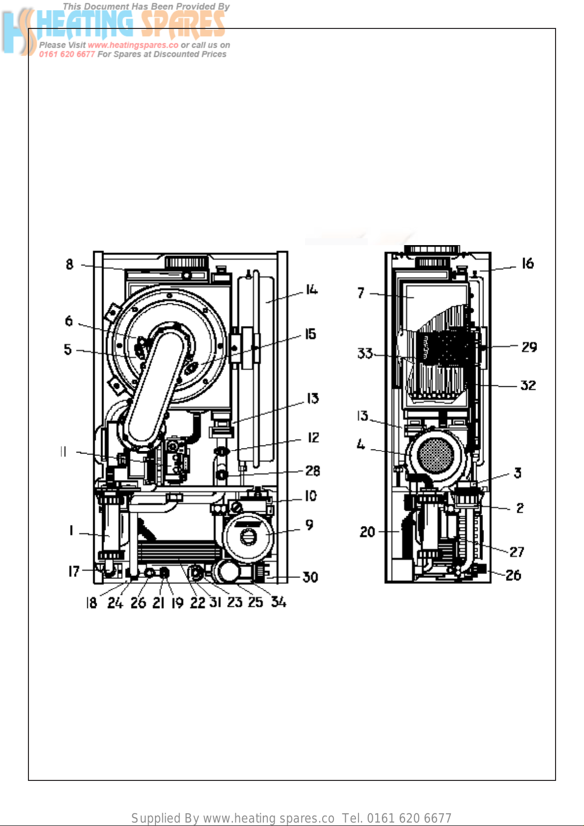
BASIC COMPONENTS - (See fi gure 1)
Guarantee is a full 12 months from date of purchase providing the appliance has been fi tted in accordance with these instructions
and relevant codes of practice.
MAJOR COMPONENTS
- Gas valve.
- Variable head pump suitable for any type of central heating system.
- Burner with fl ame stabiliser designed to operate under all thermal conditions.
- Primary heat exchanger constructed from stainless steel.
- Unique patented condensing heat exchanger for high thermal fl ue transfer gases to water.
- Stainless steel plate heat exchanger for super high heat transfer to domestic hot water.
- Highly reliable diverter valve with ethylene propylene diaphragm permitting primary fl ow circulation
in the boiler during domestic hot water supply.
- Built in frost protection.
- Printed circuit board designed to connect to room stat and/or timer/frost stat. Aesthetically pleasing
panels and controls.
- On/Off ball valves for shutting off gas central heating and domestic hot water circuit Safety relief
valve (for safety discharge).
Programmable 7 day module with digital display (optional model).
All front panel controls not often used have been hidden. This achieves simplicity of operation with easy to clean
panels.
NOTE: Due to the high effi ciency of this boiler a plume of water vapour will form at the fl ue
terminal during operation.
COSHH - CONTROL OF SUBST ANCES HARMFUL T O HEALTH
IMPORT ANT
This appliance contains materials that are indicated below.
It is the Users/Installers responsibility to ensure that the necessary personal protective clothing is-worn when handling, where applicable, the pertinent parts that contain any materials that could be interpreted as being injurious to
health and safety.
WARNING When installing the appliance, care should be taken to avoid any possibility of injury when handling sheet
metal parts.
GENERAL INFORMATION:
GLUES AND SEALANTS - exercise caution - if these are still in liquid form.
INSULATION PADS, CERAMIC FIBRE - may be harmful if inhaled, may be irritating to skin, eyes, nose and throat.
When handling keep dust generation to a minimum, avoid inhaling and contact with skin or eyes.
When disposing of the product keep dust generation to a minimum and ensure that parts are securely wrapped.
When servicing avoid inhalation by using a vacuum cleaner or in conjunction with other tools. After handling wash
hands and other exposed parts.
RAVENHEAT use only high quality material for production of this product, in an effort to protect the environment
components should be re-cycled.
3
Page 4
Supplied By www.heating spares.co Tel. 0161 620 6677
SECTIONS
TABLE OF CONTENTS
PAGE
1
2
3
4
5
6
7
8
9
10
11
12
GENERAL LAYOUT
INTRODUCTION
DESIGN AND OPERATING SEQUENCE
TECHNICAL DATA
GENERAL REQUIREMENTS
INSTALLATION
COMMISSIONING
SERVICING INSTRUCTIONS
REPLACEMENT OF PARTS
FAULT FINDING
ELECTRICAL SYSTEM DIAGRAM
ALTERNATIVE FLUE SYSTEM
LIST OF SPARE PARTS
Fig. 1
6
6
8
10
15
25
27
29
38
40
41
44
KEY
1 - Condensing trap
2 - DC Fan Supply
3 - Ignition Module
4 - Fan
5 - Ignition electrode
6 - Sight glass
7 - Main heat exchanger
8 - Sample point
9 - Circulation pump
10 - Auto air vent valve
11 - Gas Valve
12 - Overheat cut off thermostat
13 - Retaining clips
14 - Expansion vessel
15 -
Sensing electrode
16 - Pressure test point
17 - Gas inlet
18 - C.H. outlet
19 - D.H.W. sensor
20 - Condensate drain
21 - D.H.W. outlet
22 - D.H.W. Heat exchanger
23 - D.H.W. inlet
4
24 - Drain point
25 - C.H. Return
26 - Safety relief system
27 - Three way valve
28 - C.H. sensor
29 - Burner assembly
30 - Water pressure sensor
31 - D.H.W. Switch
32 - Insulation
33 - Rear insulation
34 - Diverter valve Motor
Page 5
Supplied By www.heating spares.co Tel. 0161 620 6677
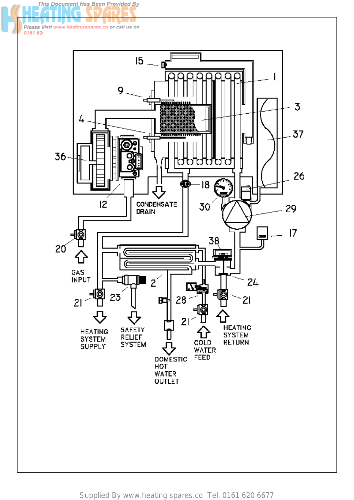
OPERATING SCHEME
Fig. 2
KEY
1 - Heat exchanger
2 - Heat exchanger for D.H.W.
3 - Burner
4 - Sensing electrode
8 - Condensing trap
9 - Ignition electrode
12 - Gas valve
15 - Sample point
17 - Water pressure switch
18 - Overheat cut-off thermostat
20 - Gas service cock
21 - Compression ball valves
23 - Safety relief system
24 - Diverter valve
26 - Auto air vent valve
28 - Pressure switch
29 - Circulating pump
30 - Water pressure gauge
36 - Fan
37 - Expansion tank
38 - Diverter valve Motor
5
Page 6

Supplied By www.heating spares.co Tel. 0161 620 6677
SECTION 1 INTRODUCTION
1.1 The Ravenheat boiler is for the production
of central and domestic hot water combined
in one unit.
It is fi tted with an automatic domestic hot
water priority valve.
A Summer/winter switch is fi tted to
the left hand side of the control panel.
With the Summer only switch position being
for domestic hot water.
The summer/winter position being for
central heating with domestic hot water
priority.
The boiler is equipped with a front cover
which can be removed for servicing. The
data badge with technical data is placed on
the lower part of the left hand side panel.
1.2 Fig.1 Illustrates the general layout of
components.
Fig.2 Illustrates the operating princi ples described in section 2.
SECTION 2
etc ,with heating circuit fully charged so as to
operate the low water sensor device the boiler
will start in the same way as domestic hot water
mode .
As the heating sensor reaches temperature
the fan speed modulates down.
When starting, the fan will always start at the
set-point speed.
2.2.8 On the control panel are mounted two
potentiometers (thermostats) these control
the temperature. One is for domestic hot
water and the other for heating.
2.2.9 The boiler is fi tted with an anti-cycling device
on the control board. This delays the boiler
from re-fi ring over a 10 minute.
If the heating temperature goes 20°C below
the set point, the burner restarts immediately .
The domestic hot water will always take
priority and is unaffected by the
anti-cycling device.
GENERAL FUNCTION
2.1 DESCRIPTION OF CONTROL SYSTEM
AND SEQUENCE OF OPERA TION
2.2 Domestic hot water mode
When the appliance is in rest mode with
the mains neon and switch on.
Switch the summer/winter switch to
Summer position, with the heating circuit
charged with water (above 1 bar). If the
domestic hot water tap is turned on,
the boiler will function in the following
sequence:
2.2.1 The pump starts.
The fan starts and sends a signal back to the
ignition board that the fan is running .
2.2.2 The spark ignition system is powered which in
turn commences the spark igniter to operate
and light the burner.
At this point the ignition board opens the gas
valve to light the burner.
2.2.3 When the electrode sensor senses the signal
of the burner, the spark igniter stops.
2.2.4 From the fan speed setting the boiler
increases to the maximum permissible speed
over a period of 5 seconds and will remain at
its maximum required power until its maximum
regulated temperature.
2.3 Central Heating Mode
2.3.1 A potentiometer installed on the panel
instruments permits regulation of the boiler
to partial heating requirements, between
maximum and minimum settings.
2.3.2 Air is drawn by the fan for combustion.
2.3.3 The fan also forces exhaust gas through the fl ue
to the outside, this creates a lesser pressure in
the sealed combustion chamber, thus sucking
in combustion air, through the inlet duct.
2.3.4 The boiler water temperature is automatically
controlled by a built in thermostat
2.3.5 Interior space temperature is set by the room
thermostat to be installed in the heating
system. The boiler already carries connection
terminals for this thermostat, as well as for a
timeclock.
The burner continues to operate until it is
stopped by the timer or one of the thermostats
2.3.6 When the internal C.H. temperature sensor
intervenes the burner shuts down. The fan
stops but the pump continues to operate.
2.3.7 When the room thermostats intervene the
burner shuts down. The fan stops and the
pump after 3 minutes turns off.
2.2.5 When the domestic hot water tap is closed the
diverter valve goes back into rest mode, the
burner is shut down along with the fan which is
also switched off.
2.2.6 Central heating mode
2.2.7 If the switch is positioned on winter
with a demand for heat to supply radiators,
2.3.8 In summer position an anti-block of the pump
6
is included. Every day the pump is powered for
a period of 2 minutes.
The boiler also incorporates an anti-block
system which powers the pump every 24
hours, allowing it operate for 2 minutes if the
boiler has not been in use. This operation may
in some cases be heard for a short period
when the pump has been activated.
Page 7

Supplied By www.heating spares.co Tel. 0161 620 6677
2.4 Domestic hot water mode
2.4.1 The heat exchanger in the D.H.W. circuit is
a stainless steel plate heat exchanger water
to water, and domestic water is heated by
converting the water in the central heating
circuit. The transference of heat is very high
because the two fl uids move in a counter
direction fl ow to each other.
2.4.2 Switch 1a Fig.50 in the winter position.
When a hot water tap is turned on a
diaphragm diverter valve excludes the central
heating circuit, the boiler automatically
modulates to maintain the domestic
hot water at a constant temperature.
Water temperature can be regulated using
the D.H.W. thermostat located on the front
control panel.
2.4.4 When D.H.W. is no longer called for the boiler
automatically returns to the central heating
mode.
2.4.5 Switch 1a in the Fig.50 in summer position
The boiler functions like an automatic gas
hot water heater When D.H.W. is no longer
required the burner and fan immediately turn
off.
This also takes place when switch 1a is on
Winter if there is no demand for
heat to the central heating system or until
the room thermostat/time clock demands for
central heating circuit.
2.5 SAFETY DEVICE
In both central heating and domestic hot
water mode safe operating is ensured by a
control board shuts off the main burner if the
fan stops or the fl ue or combustion air intake
duct is obstructed
2.4.3 When domestic hot water is being drawn the
burner and pump perform as they do during
central heating except that the burner is
commanded by the D.H.W. thermostat.
OVERALL DIMENSION
Fig.3
2.5.1 An overheat cut off thermostat acts to
turn of the burner to resetable “lockout”
(Fig. 50) .
2.5.2 A safety valve is fi tted on the central heating
circuit set at 3 bar.
2.5.3 A low water pressure switch set at 0.4 bar is
fi tted on heating circuit.
AVAILABLE PUMP HEAD
Fig.4
PRESSURE DROP ACROSS APPLIANCE
Fig.5
7
Page 8

Supplied By www.heating spares.co Tel. 0161 620 6677
SECTION 3 TECHNICAL DATA
HE 120N (T) Low Nox
TABLE 1
NATURAL GAS (G 20) І2H - П2H3+
NOMINAL HEAT INPUT NET QMS 26.0 kW
MINIMUM HEAT INPUT NET 5.78 kW
NOMINAL HEAT OUTPUT 25.7 kW
NOMINAL HEAT OUTPUT CONDENSING 28.8 kW
MINIMUM HEAT OUTPUT 5.72 kW
MINIMUM HEAT OUTPUT CONDENSING 6.41 kW
3
GAS RATE max 2.7 m
AFTER 10 MINUTES min 0.6 m3/h
INLET PRESSURE 20 mbar
FAN SPEED C.H. Max 175 Hz Combustion % CO2 : G20 - 9.0 (+ 0.2 / - 0.5)
min 47 Hz with the Case OFF
BURNER INJECTORS Nr. 1 x 5.6
ELECTRICAL SUPPLY 230 V ~ 50 HZ
POWER CONSUMPTION 160 W
EXTERNAL FUSE RATING 3A
INTERNAL FUSE F1 - 3.15 A / F2 - 315 mA (20 mm to BS 4265)
/h
DRY WEIGHT 40 kg
WATER CONTENT C.H. 2.0 litre
WATER CONTENT 0.5 litre
GAS SUPPLY CONNECTION 15 mm compression isolating valve
FLOW CONNECTION C.H. 22 mm compression isolating valve
RETURN CONNECTION C.H. 22 mm compression isolating valve
INLET CONNECTION D.H.W. 15 mm compression isolating valve
OUTLET CONNECTION D.H.W. 15 mm copper pipe
SAFETY DISCHARGE C.H. 15 mm copper pipe
CONDENSATION DRAIN 3/4” (21.5 mm) push fi t over fl ow
MAX COLD WATER CAPACITY WITHOUT ADDITIONAL EXPANSION VESSEL 110 LITRE
SEALED WATER SYSTEM C.H.
MAX PRESSURE PHS 2.5 bar
MINIMUM WORKING PRESSURE 0.5 bar
7 LITRES EXPANSION VESSEL PRE-CHARGE-PRESSURE 0.5 bar
CENTRAL HEATING OPERATING TEMPERATURE MAX 85°C min 40°C
DESIGN FLOW RATE 1383 I/h 20 °C RISE
MINIMUM FLOW RATE C.H. 503 I/min
D.H.W. FLOW RATE 30 °C rise 15.4 l/min
D.H.W. FLOW RATE 35 °C rise 13.2 l/min
D.H.W. FLOW RATE 40 °C rise 11.5 l/min 10°C inlet temperature
D.H.W. TEMPERATURE Max 60 °C min 40 °C
FAN SPEED D.H.W. Max 205 Hz min 47 Hz
Qmw Input Net Max 32.5 kW min 5.78 kW
D.H.W. PRESSURE PMW Max 10 bar (147 p.s.i.)
D.H.W. PRESSURE PMW min 0.8 bar (118 p.s.i.) To obtain heat input 1.2 bar
D.H.W. MINIMUM FLOW RATE 3 I/min
FLUE OUTLET NOM. DIAMETER 100 mm specially supplied with boilers (If required)
DESTINATION: AT, DK, Fl, SE CATEGORY I
2H
DESTINATION: GB, IE, CH, ES, IT, PT CATEGORY II2H3+
FLUE TYPE - C13 - C33 - C53 NOX 5 SEDBUK
A
8
Page 9
Supplied By www.heating spares.co Tel. 0161 620 6677
SECTION 3 TECHNICAL DATA
HE 120N (T) Low Nox
TABLE 1/A
LPG (G 30 - G 31) І3+ - П2H3+
NOMINAL HEAT INPUT NET QMS 26.0 kW
MINIMUM HEAT INPUT NET 5.78 kW
NOMINAL HEAT OUTPUT 25.7 kW
NOMINAL HEAT OUTPUT CONDENSING 28.8 kW
MINIMUM HEAT OUTPUT 5.72 kW
MINIMUM HEAT OUTPUT CONDENSING 6.41 kW
3
GAS RATE max G31 0.9 m
AFTER 10 MINUTES min 0.4 m3/h 0.3 m3/h
INLET PRESSURE G31 37 mbar G30 28-30 mbar
FAN SPEED C.H. Max 160 Hz Combusiton % CO2 : G31 - 10.2 (+ 0.2 / - 0.5)
min 44 Hz with the Case OFF G30 - 11.0 (+ 0.2 / - 0.5)
BURNER INJECTORS Nr. 1 x 5.6
ELECTRICAL SUPPLY 230 V ~ 50 HZ
POWER CONSUMPTION 160 W
EXTERNAL FUSE RATING 3A
INTERNAL FUSE F1 - 3.15 A / F2 - 315 mA (20 mm to BS 4265)
/h G30 0.7 m3/h
DRY WEIGHT 40 kg
WATER CONTENT C.H. 2.0 litre
WATER CONTENT 0.5 litre
GAS SUPPLY CONNECTION 15 mm compression isolating valve
FLOW CONNECTION C.H. 22 mm compression isolating valve
RETURN CONNECTION C.H. 22 mm compression isolating valve
INLET CONNECTION D.H.W. 15 mm compression isolating valve
OUTLET CONNECTION D.H.W. 15 mm copper pipe
SAFETY DISCHARGE C.H. 15 mm copper pipe
CONDENSATION DRAIN 3/4” (21.5 mm) push fi t over fl ow
MAX COLD WATER CAPACITY WITHOUT ADDITIONAL EXPANSION VESSEL 110 LITRE
SEALED WATER SYSTEM C.H.
MAX PRESSURE PHS 2.5 bar
MINIMUM WORKING PRESSURE 0.5 bar
7 LITRES EXPANSION VESSEL PRE-CHARGE-PRESSURE 0.5 bar
CENTRAL HEATING OPERATING TEMPERATURE MAX 85°C min 40°C
DESIGN FLOW RATE 1383 I/h 20 °C RISE
MINIMUM FLOW RATE C.H. 503 I/min
D.H.W. FLOW RATE 30 °C rise 15.4 l/min
D.H.W. FLOW RATE 35 °C rise 13.2 l/min
D.H.W. FLOW RATE 40 °C rise 11.5 l/min 10°C inlet temperature
D.H.W. TEMPERATURE Max 60 °C min 40 °C
FAN SPEED D.H.W. Max 190 Hz min 44 Hz
Qmw Input Net Max 32.5 kW min 5.78 kW
D.H.W. PRESSURE PMW Max 10 bar (147 p.s.i.)
D.H.W. PRESSURE PMW min 0.8 bar (118 p.s.i.) To obtain heat input 1.2 bar
D.H.W. MINIMUM FLOW RATE 3 I/min
FLUE OUTLET NOM. DIAMETER 100 mm specially supplied with boilers (If required)
DESTINATION: BE, FR CATEGORY I
3+
DESTINATION: GB, IE, CH, ES, IT, PT CATEGORY II2H3+
FLUE TYPE - C13 - C33 - C53 NOX 5 SEDBUK
A
9
Page 10
Supplied By www.heating spares.co Tel. 0161 620 6677
SECTION 3 TECHNICAL DATA
HE 150N(T) Low Nox
TABLE 1
NATURAL GAS (G 20) І2H - П2H3+
NOMINAL HEAT INPUT NET QMS 32.0 kW
MINIMUM HEAT INPUT NET 8.0 kW
NOMINAL HEAT OUTPUT 31.7 kW
NOMINAL HEAT OUTPUT CONDENSING 34.9 kW
MINIMUM HEAT OUTPUT 7.93 kW
MINIMUM HEAT OUTPUT CONDENSING 8.73 kW
3
GAS RATE max 3.4 m
AFTER 10 MINUTES min 0.85 m3/h
INLET PRESSURE 20 mbar
FAN SPEED C.H. Max 180 Hz Combustion % CO2 : G20 - 9.0 (+ 0.2 / - 0.5)
min 53 Hz with the Case OFF
BURNER INJECTORS Nr. 1 x 6
ELECTRICAL SUPPLY 230 V ~ 50 HZ
POWER CONSUMPTION 160 W
EXTERNAL FUSE RATING 3A
INTERNAL FUSE F1 - 3.15 A / F2 - 315 mA (20 mm to BS 4265)
/h
DRY WEIGHT 42 kg
WATER CONTENT C.H. 2.0 litre
WATER CONTENT 0.5 litre
GAS SUPPLY CONNECTION 15 mm compression isolating valve
FLOW CONNECTION C.H. 22 mm compression isolating valve
RETURN CONNECTION C.H. 22 mm compression isolating valve
INLET CONNECTION D.H.W. 15 mm compression isolating valve
OUTLET CONNECTION D.H.W. 15 mm copper pipe
SAFETY DISCHARGE C.H. 15 mm copper pipe
CONDENSATION DRAIN 3/4” (21.5 mm) push fi t over fl ow
MAX COLD WATER CAPACITY WITHOUT ADDITIONAL EXPANSION VESSEL 110 LITRE
SEALED WATER SYSTEM C.H.
MAX PRESSURE PHS 2.5 bar
MINIMUM WORKING PRESSURE 0.5 bar
7 LITRES EXPANSION VESSEL PRE-CHARGE-PRESSURE 0.5 bar
CENTRAL HEATING OPERATING TEMPERATURE MAX 85°C min 40°C
DESIGN FLOW RATE 1811 I/h 20 °C RISE
MINIMUM FLOW RATE C.H. 503 I/min
D.H.W. FLOW RATE 30 °C rise 20.1 l/min
D.H.W. FLOW RATE 35 °C rise 17.3 l/min
D.H.W. FLOW RATE 40 °C rise 15.1 l/min 10°C inlet temperature
D.H.W. TEMPERATURE Max 60 °C min 40 °C
FAN SPEED D.H.W. Max 210 Hz min 53 Hz
Qmw Input Net Max 42.5 kW min 8.0 kW
D.H.W. PRESSURE PMW Max 10 bar (147 p.s.i.)
D.H.W. PRESSURE PMW min 0.8 bar (118 p.s.i.) To obtain heat input 1.2 bar
D.H.W. MINIMUM FLOW RATE 3 I/min
FLUE OUTLET NOM. DIAMETER 100 mm specially supplied with boilers (If required)
DESTINATION: AT, DK, Fl, SE CATEGORY I
2H
DESTINATION: GB, IE, CH, ES, IT, PT CATEGORY II2H3+
FLUE TYPE - C13 - C33 - C53 NOX 5 SEDBUK
A
10
Page 11
Supplied By www.heating spares.co Tel. 0161 620 6677
SECTION 3 TECHNICAL DATA
HE 150N (T) Low Nox
TABLE 1/A
LPG (G 30 - G 31) І3+ - П2H3+
NOMINAL HEAT INPUT NET QMS 32.0 kW
MINIMUM HEAT INPUT NET 8.0 kW
NOMINAL HEAT OUTPUT 31.7 kW
NOMINAL HEAT OUTPUT CONDENSING 34.9 kW
MINIMUM HEAT OUTPUT 7.93 kW
MINIMUM HEAT OUTPUT CONDENSING 9.06 kW
3
GAS RATE max G31 1.3 m
AFTER 10 MINUTES min 0.3 m3/h 0.25 m3/h
INLET PRESSURE 20 mbar
FAN SPEED C.H. Max 155 Hz Combusiton % CO2 : G31 - 10.2 (+ 0.2 / - 0.5)
min 48 Hz with the Case OFF G30 - 11.0 (+ 0.2 / - 0.5)
BURNER INJECTORS Nr. 1 x 6
ELECTRICAL SUPPLY 230 V ~ 50 HZ
POWER CONSUMPTION 160 W
EXTERNAL FUSE RATING 3A
INTERNAL FUSE F1 - 3.15 A / F2 - 315 mA (20 mm to BS 4265)
/h G30 0.99 m3/h
DRY WEIGHT 42 kg
WATER CONTENT C.H. 2.0 litre
WATER CONTENT 0.5 litre
GAS SUPPLY CONNECTION 15 mm compression isolating valve
FLOW CONNECTION C.H. 22 mm compression isolating valve
RETURN CONNECTION C.H. 22 mm compression isolating valve
INLET CONNECTION D.H.W. 15 mm compression isolating valve
OUTLET CONNECTION D.H.W. 15 mm copper pipe
SAFETY DISCHARGE C.H. 15 mm copper pipe
CONDENSATION DRAIN 3/4” (21.5 mm) push fi t over fl ow
MAX COLD WATER CAPACITY WITHOUT ADDITIONAL EXPANSION VESSEL 110 LITRE
SEALED WATER SYSTEM C.H.
MAX PRESSURE PHS 2.5 bar
MINIMUM WORKING PRESSURE 0.5 bar
7 LITRES EXPANSION VESSEL PRE-CHARGE-PRESSURE 0.5 bar
CENTRAL HEATING OPERATING TEMPERATURE MAX 85°C min 40°C
DESIGN FLOW RATE 1811 I/h 20 °C RISE
MINIMUM FLOW RATE C.H. 503 I/min
D.H.W. FLOW RATE 30 °C rise 20.1 l/min
D.H.W. FLOW RATE 35 °C rise 17.3 l/min
D.H.W. FLOW RATE 40 °C rise 15.1 l/min 10°C inlet temperature
D.H.W. TEMPERATURE Max 60 °C min 40 °C
FAN SPEED D.H.W. Max 195 Hz min 48 Hz
Qmw Input Net Max 42.5 kW min 8.0 kW
D.H.W. PRESSURE PMW Max 10 bar (147 p.s.i.)
D.H.W. PRESSURE PMW min 0.8 bar (118 p.s.i.) To obtain heat input 1.2 bar
D.H.W. MINIMUM FLOW RATE 3 I/min
FLUE OUTLET NOM. DIAMETER 100 mm specially supplied with boilers (If required)
DESTINATION: AT, DK, Fl, SE CATEGORY I
2H
DESTINATION: GB, IE, CH, ES, IT, PT CATEGORY II2H3+
FLUE TYPE - C13 - C33 - C53 NOX 5 SEDBUK
A
11
Page 12
Supplied By www.heating spares.co Tel. 0161 620 6677
SECTION 4 GENERAL REQUIREMENTS
4.1 SAFETY
Gas Safety (Installation and Use)
Regulations, 1994 and amended 2000.
It is law that all gas appliances are installed
and serviced by a CORGI registered installer
in accordance with the above regulations
and these installation instructions. All CORGI
registered installers carry a CORGI I.D. card
and have a registration number. Both should
be recorded in your boiler log book. You can
check your installer by calling CORGI direct
on: 01256 732300. Failure to install appliances
correctly could lead to prosecution. It is in
your own interest, and that of safety , to ensure
the law is complied with. Check the boiler
and flue is the correct type for installation.
The installation of the boiler MUST be
in accordance with the latest I.E.E. (BS
7671) Wiring Regulations, local building
regulations, bye-laws of the local water
authority, the building regulations and the
Building Standards (Scotland) and any
relevant requirements of the local authority.
4.1.1 GENERAL INFORMATION
Both the user and the manufacturer rely
heavily on the installer, whose job it is to
install the combination boiler and connect
it to a correctly designed heating system.
Acquaint yourself with the British Standards
concerning installation requirements. If you
need advice on any points your Ravenheat
Technical Services Office would be pleased to
help. It is recommended that tools suitable for
brass fittings are used, and have a capability
to accomodate hexagon sizes up to 50 mms.
CODES OF PRACTICE/Ref: Documents
Detailed recommendations are contained in the
following British Standard Codes of Practice:
BS.6891 Low pressure installation pipes.
BS.6798 Installation of gas fired hot water
boilers of rated input not exceeding
60 kW.
BS.5449 Forced circulation hot water systems.
The manufacturer’s notes must NOT be
taken, in any way, as overriding statutory
obligations.
IMPORTANT:
These appliances are CE certificated for
safety and performance. It is, therefore,
important that no external control devices e.g.
flue dampers, economisers etc., are directly
connected to this appliance unless covered by
these Installation and Service Instructions or
as otherwise recommended by Ravenheat in
writing. If in doubt please enquire.
Any direct connection of a control device
not approved by Ravenheat could invalidate
the certification and the normal appliance
warranty.
It could also infringe the Gas Safety regulations
and the above regulations.
NOTE:
The Ravenheat HE combination boiler has
been tested and examined by BG, and is
certified to comply with PrEN 483 and BS EN
625.
Manufactures instructions must NOT be taken
in any way as overriding statutory obligations.
If in doubt on any point please consult
Ravenheat Manufacturing Ltd.
4.2 LOCATION OF BOILER
4.2.1 Siting of Ravenheat HE Combi Boiler must be
as follows.
The position of installation should be within
the building, unless otherwise protected by a
suitable enclosure.
Adequate space for installation, servicing and
air circulation around boiler must be allowed
for.
The Ravenheat HE Combi Boiler must be
fitted on a flat and vertical wall capable of
adequately supporting the weight of the boiler
and any ancillary equipment.
The appliance may be installed on a combustible
wall subject to the requirements of the Local
Authority and Building Regulations.
LPG versions of this appliance shall not be
installed in cellars or basements.
BS.5546 Installation of gas hot water supplies
domestic purposes (2ndFamily
Gases).
BS.5440: 1 Flues (for gas appliances of rated
input not exceeding 60 kW).
BS.5440: 2 Ventilation (for gas appliances of
rated input not exceeding 60 kW).
DD 189: 1990 Discharge of condensate.
Health & Safety Document No.635
The Electricity at Work Regulations, 1989.
4.3 CLEARANCES AROUND THE APPLIANCE
4.3.1 The following minimum free spaces, required
18 inches (450 mm) in front
5 inches (125 mm) above
6 inches (150 mm) below
0.2 inches (5 mm) on each side
1 inch (25 mm) in front when installed in a
12
for installation inspection and servicing, must
be left around the boiler
cupboard.
Page 13
Supplied By www.heating spares.co Tel. 0161 620 6677
4.4 IMPORTANT NOTICE
4.6 FLUE SYSTEM
4.4.1 For installation into timber framed buildings,
please refer to the Institute of Gas Engineers
Document IGE UP/7 instead of DM2
If in doubt advice must be sought from the local
gas supplier The combination boiler may be
installed in any room or internal space, although
particular attention is drawn to the requirements
of the current I.E.E. Wiring Regulations, and in
Scotland the electrical provisions of the Building
Regulations applicable in Scotland, with respect
to the installation of the combination boiler in
a room or internal space containing a bath or
shower. Where a room sealed appliance is
installed in a room containing a bath or shower,
any electrical switch or appliance control,
utilising mains electricity should be so situated
that it cannot be touched by a person using a
bath or shower.
A compartment used to enclose the combination
boiler MUST be designed and constructed
specifically for this purpose. An existing
cupboard, or compartment, may be used
provided it is modified accordingly Samples
of the CSI combination boiler have been
examined by B.G. Technology Notified Body,
and is certified to comply with the essential
requirements of the Gas Appliance
Directive 90/396/EEC, the Low Voltage
Directive 72/23/EEC and shows compliance
with the Electro Magnetic Compatibility
Directive 89/336/EEC and are therefore
permitted to carry the CE Mark.
The appliance has been tested and approved
by the WRc as meeting the requirements of
G3 and L of the Building regulations and water
Bylaws Scheme - Approved Products.
4.5 GAS SUPPLY
4.5.1 A gas meter is connected to the service pipe
by the Local Gas Region or the Local Gas
Region contractor. An existing meter should
be checked preferably by the Gas Region to
ensure that the meter is adequate to deal with
the rate of gas supply required for all appliances
it serves. Installation pipes should be fitted in
accordance with BS 6891. Pipework from the
meter to the boiler must be of adequate size
(22 mm) min To within at least 3 metre of
the boiler (15 mm) min. can then be used for
remaining pipe work to the appliance. A smaller
size than the boiler inlet gas connection should
not be used The complete installation must be
tested for soundness as described in the above
Code
N.B. if the gas supply for the boiler serves
other appliances ensure an adequate
supply is available both to the boiler and the
other appliances when they are in use at the
same time.
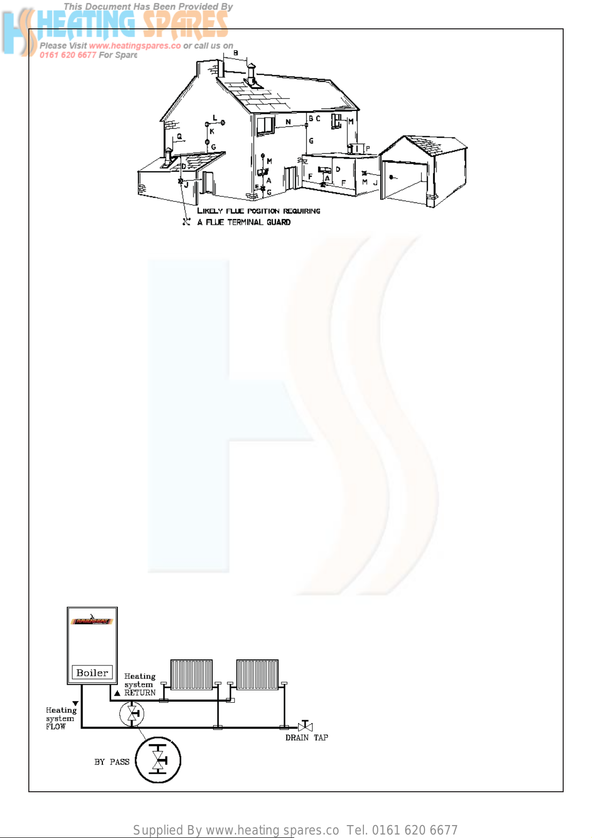
4.6.1 The terminal should be located where
dispersal of combustion products is not
impeded and with due regard for the damage
or discolouration that might occur to building
products in the vicinity (see fig. 6).
The terminal must not be located in a place
where it is likely to cause a nuisance In cold
and/or humid weather water vapour may
condense on leaving the flue terminal.
The effect of such steaming must be
considered
The terminal must not be closer than 25 mm
(1 in) to any combustible material For protection
of combustibles, refer to BS 5440.1.
Where a flue terminal is installed less than
1000 mm. from a plastic, or painted gutter;
or 500 mm from painted eaves, an aluminium
shield 1000 mm. long, should be fitted to the
underside of the gutter or painted surface.
Pluming will occur at the terminal so, where
possible, terminal positions which could cause
a nuisance should be avoided.
The flue must be installed in accordance with
the recommendations of BS 5440: Part 1.
IMPORTANT NOTES
For greater fl ue lengths see alternative fl ue
instructions. Flue must be positioned in a
place not likely to cause a nuisance from
pluming.
IMPORTANT NOTICE: If the fl ue terminates
less a balcony, above the ground, or above
a fl at roof to which people have access,
then a suitable terminal guard must be
fi tted. 0001PRO06005/0
Fit only recommended FLUE TERMINAL
GUARD by securing concentrically around
terminal with screws.
Available on request from:
RAVENHEAT Manufacturing Ltd
Morley, Leeds, West Yorkshire
ENGLAND LS27 9ET - UK
Tel.0044(0)113 252 7007
IMPORTANT: The following notes are intended
for general guidance
The boiler MUST be installed so that the
terminal is exposed to external air.
It is important that the position of the terminal
allows the free passage of air across it at all
tirnes.
Minimum acceptable spacing from the terminal to
obstructions and ventnation opening are specifi ed
in Fig. 6.
Note positions: Due to the terminal design,
installation is possible with clearances less than
those specifi ed in BS 5440, Part 1
13
Page 14
Supplied By www.heating spares.co Tel. 0161 620 6677
Fig.6
Terminal position for fan assisted boiler
(minimum distance) mm
A - Directly below an open window or other 300
opening (e.g. air brick)
B - Below gutters, soil pipes or drain pipes 75
C - Below eaves 150
D - Below balconies or car port roof 200
E - From vertical drain pipes and soil pipes 150
F - From internal or external corners 300
G - Above ground or below balcony level 300
H - From a surface facing a terminal 600
I - From a terminal facing a terminal 1200
J - From an opening in the car port
(e.g. door window) into dwelling. 1200
K - Vertically from a terminal on the same wall 1500
L - Horizontally from a terminal on the same wall 300
M - From adjacent wall to flue 300
NOTE: The flue must be terminated in a place not
likely to cause a nuisance.
4.6.2 A concentric vertical flue kit is available for
flueing applications up to a maximum height of
4 metres.
For further details see vertical flue installation
instructions.
4.7 AIR SUPPLY
4.7.1 The following notes are intended for general
guidance.
The room sealed fan flued boiler does not
require a permanent air vent for combustion
air supply.
Where installed in a cupboard or compartment
ventilation is not required.
4.8 WATER CIRCULATION (central heating)
4.8.1 Detailed recommendations are given in
BS 6798:1987/5449:1990 (for smallbore
and microbore central heating systems).
The following notes are given for general
guidance.
4.8.2 Pipework
Copper tubing to BS 2871 1.1.1971 is
recommended for water pipes. Jointing should
be either with capillary soldered or with
compression fittings.
Where possible pipes should have a gradient
to ensure air is carried naturally to air release
points and water flows naturally to drain taps.
It should be ensured as far as possible that
the appliance heat exchanger is not a natural
collecting point for air except where providing
useful heat, pipes should be insulated to
prevent heat loss and to avoid freezing.
Particular attention should be paid to pipes
passing through ventilated spaces in roofs and
under floors.
4.8.3 The water through the appliance heat
exchanger circuit must exceed the min. 2.38
gals/min. (650 It/h) when the burner is firing. It
is important to ensure that this rate is achieved
when sections of the system are shut off either
manually or by automatic controls.
Therefore a by-pass must be fitted to the
system (15 mm min.) (Fig. 6A).
If the volume of circulating water is too low, the
boiler water temperature will rise too rapidly.
This could cause noise in the system or even
cause the safety thermostat to trip.
14
Fig.6A
Page 15
Supplied By www.heating spares.co Tel. 0161 620 6677
4.8.4 Draining tap
These must be located in accessible positions
to permit the draining of the whole system.
The taps must be at least 15 mm nominal size
and manufactured in accordance with BS 2870
1980.
4.8.5 Air release points
These must be fitted at all high points where
air will naturally collect, and must be sited to
facilitate complete filling of the system.
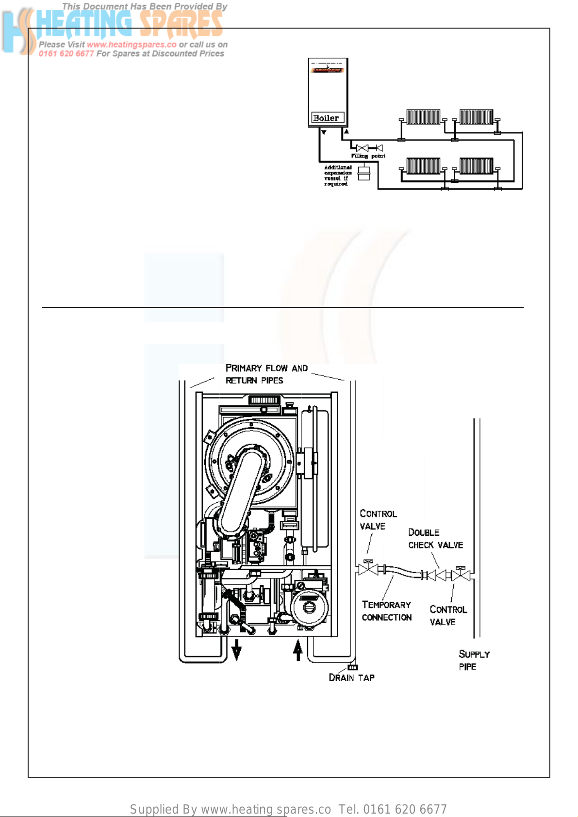
4.8.6 The appliance has an integral sealed expansion
vessel to accommodate the increase of water
volume when the system is heated.
It can accept up to 6 Its of expansion water.
If the appliance is connected to a system with
an unusually high water content, calculate
the total expansion and add additional sealed
expansion capacity as appropriate (Fig. 7).
In general, modern systems will present no
problem.
4.8.8 Permissible methods of filling
Fig.7
4.8.7 Mains water feed: central heating
There must be no direct connection to the
mains water supply, even through a nonreturn
valve, without the approval of the Local Water
Authority.
Fig.8
Figure depicts the requirements of Diagram R24.2a of
the Water Supply (Water Fittings) regulations 1999.
15
Page 16
Supplied By www.heating spares.co Tel. 0161 620 6677
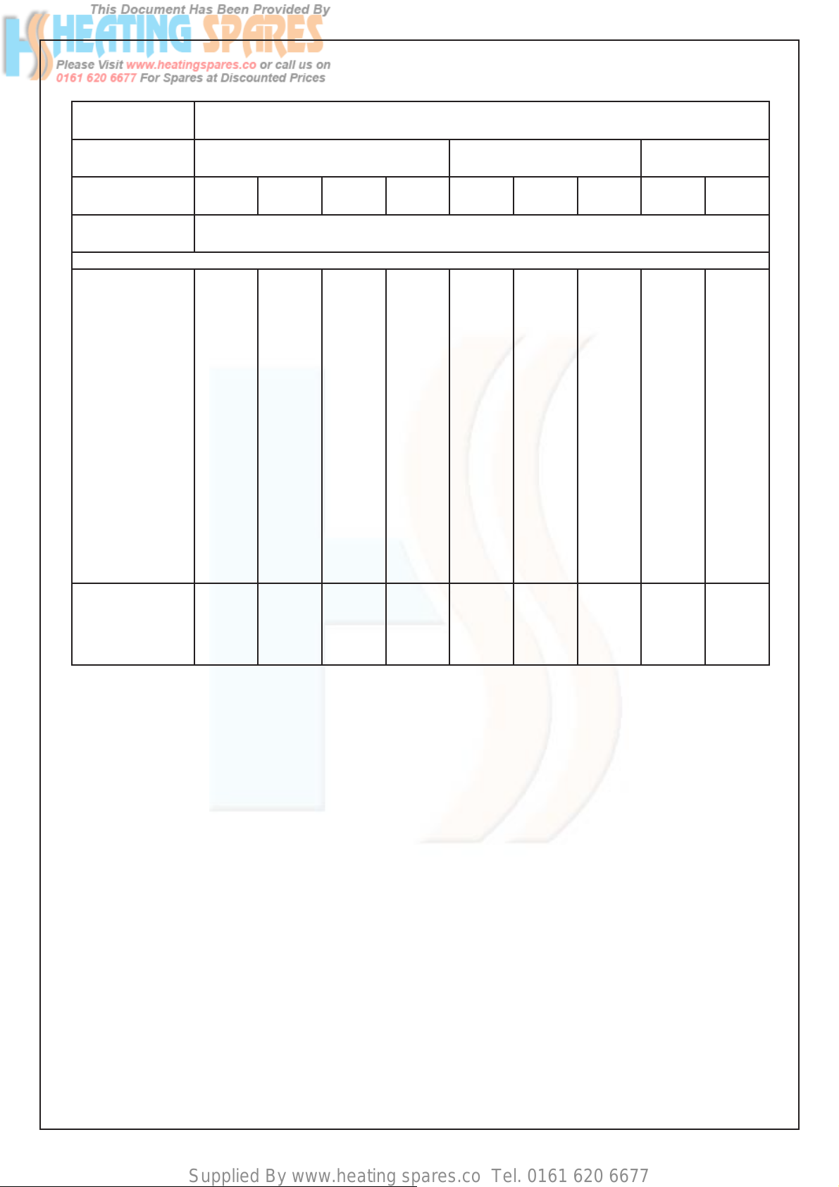
SIZING OF ADDITIONAL EXPANSION VESSEL: TABLE 3
Deduct from the value given in the table the 7 litre vessel supplied.
Safety
valve setting (bar)
Vessel charge
pressure (bar)
Initial system
pressure (bar)
T otal water
content of system
Litres
25
50
75
100
125
150
175
200
225
250
275
300
325
350
375
400
425
450
475
500
3.0
0.5 1.0 1.5
0.5 1.0 1.5 2.0 1.0 1.5 2.0 1.5 2.0
EXPANSION VESSEL VOLUME (LITRES)
2.1
4.2
6.3
8.3
10.4
12.5
14.6
16.7
18.7
20.8
22.9
25.0
27.0
29.1
31 .2
33.3
35.4
37.5
39.6
41.6
3.5
7.0
10.5
14.0
17.5
21.0
24.5
28.0
31 .5
35.0
38.5
42.0
45.5
49.0
52.5
56.0
59.5
63.0
66.5
70.0
6.5
12.9
19.4
25.9
32.4
38.8
45.3
51 .8
58.3
64.7
71 .2
77.7
84.1
90.6
97 .1
103.6
110.1
116.5
123.0
125.9
13.7
27.5
41.3
55.1
68.9
82.6
96.4
110.2
124.0
137.7
151 .5
165.3
179 .1
192.8
206.6
220.4
239.2
247.9
261 .7
275.5
2.7
5.4
8.2
10.9
13.6
16.3
19.1
21.8
24.5
27.2
30.0
32.7
35.7
38 .1
40.9
43.6
46.3
49.0
51 .8
54.5
4.7
9.5
14.2
19.0
23.7
28.5
33.2
38.0
42.7
47.5
52..2
57.0
61 .7
66.5
71 .2
76.0
80.7
85.5
90.2
95.0
10.3
20.6
30.9
41.2
51.5
61.8
72.1
82.4
92.7
103.0
1
13.3
123.6
133.9
144.2
154.5
164.8
175.1
185.4
195.7
206.0
3.9
7.8
11.7
15.6
19.5
23.4
27 .3
31.2
35 .1
39.0
42.9
46.8
50.7
54.6
58.5
62.4
66.3
70.2
74.1
78.0
107.6
115.8
124.1
132.4
140.7
148.9
157.2
165.5
8.3
16.5
24.8
33.1
41.3
49.6
57.9
66.2
74.5
82.7
91.0
99.3
For system volumes
other than those given
above, multiply the
system volume by
the factor across
Note: This pressure can be increased up to 1.5 bar to suit high static head situations, see item 10, other appliance components in the
SERVICING INSTRUCTIONS.
B) Where fitting of a make up vessel would be
difficult, re pressurisation of the system can be
done. See section on FILLING. If the capacity
of the central heating system should exceed
110 Litres, an additional vessel should be
installed on the return to the combination boiler
from the heating system (Fig. 7). Guidance on
vessel sizing is given in (Table 3).
Reference should be made to British Gas
Publications, «Material and Installation
Specifications for Domestic Central Heating
and Hot Water». Draining taps should be
at least 1/2” in BSP nominal size and be in
accordance with BS 2879.
4.8.9 Installation to an existing central heating
system
The combination boiler is designed to operate
on a sealed system only. Therefore if the
existing system is of the open water type it will
0.0833 0.140
0.259 0.551 0 .109 0.190 0.412 0.156 0.331
If the boiler is installed in an existing system
any unsuitable additives MUST be removed
by thorough cleaning.
BS 7593:1992 details the steps necessary to
clean domestic central heating system. Also
check pipework and renew any corroded
pipework or fittings. Valve glands must be
repacked or replaced wherever necessary
and any defective controls exchanged.
WATER TREATMENT
This boiler has a stainless steel heat
exchanger Ravenheat recommended only the
use of FERNOX- COPAL or SENTINEL X100
water treatment products, which must be
used in accordance with the manufacturers
instructions. For further information contact:
Fernox Manufacturing Co. Ltd.
Tel 01799 550811
Sentinel Division Betz Dearborn Ltd.
Tel. (0151) 424 5351
have to be modified to comply with BS 5376
Part 2.
Before installing a new combination boiler to
an existing system, flush out the old system
with a recommended descaling agent.
16
Page 17

Supplied By www.heating spares.co Tel. 0161 620 6677
SALAMANDER CORROSION GUARD
Salamander (Eng) Ltd
Tel: (0121) 3780952 /4508
4.8.10 Hard water areas
If the area of installation is recognized as hard
water, it is recommended that a suitable water
treatment device is installed in the mains.
The water hardness can be determined by using
the standard test paper or by referring to local
water authority.
4.9 DOMESTIC WATER
4.9.1 The domestic hot water must be in accordance
with the relevant recommendations of BS 5546.
Copper tubing to BS 2871 1 is recommended
for water carrying pipework and MUST be used
for pipework carrying potable water.
4.10 ELECTRICAL SUPPLY
Warning: this appliance must be earthed
4.10.1 External wiring to the appliance must be carried
out by a competent person and be in accordance
with the current I.E.E. Regulations and local
regulations which apply . The Ravenheat boiler is
supplied for connection to a 230 V ~ 50 Hz single
phase supply . The supply must be fused at 3 A.
NOTE. The method of connection to the
electricity supply MUST facilitate complete
electrical isolation of the appliance, by the
use of a fused, double pole isolator, having a
contact separation of at least 3 mm in all poles.
The point of connection to the electricity supply
must be readily accessible and adjacent to
the appliance except, where the appliance is
installed in a bathroom, this MUST be sited
outside the bathroom.
SECTION 5 INSTALLATION
5.1 WARNING
5.2 DELIVERY
5.2.1 The appliance carton containing
a) boiler fully assembled with fl ue adaptor
b) installation instructions ,
user instructions and Benchmark log book
c) white paper template
d) hanging bracket
e) guarantee card
f ) Polythene bag containing
- 2-22 mm compression ball valves
complete with 3/4” washers
- 1-15 mm compression ball valves
complete with 1/2” washers
- 1- 15 mm compression ball valve
- 2 coach bolts and wall plugs
- screws and dowels
5.3 UNPACKING OF BOILER
5.3.1 IMPORTANT: With regards to the Manual
Handling Operations, 1992 Regulations,
the following lift operation exceeds the
recommended weight for a one man lift.
5.3.2 - Stand the boiler carton upright.
- Open the top of the carton
- Rest the carton on the fl oor
(keeping the fl aps open)
- Turn the carton over with the boiler inside
and then pull tha carton
- Rest the boiler on the fl oor and remove the
polystyrene guards
5.4 POSITIONING OF THE BOILER
5.4.1 Remove the 2 lower and the 2 upper
screws that secure of the front panel,
and then lift off .
5.4.2 Unscrew the 4 screws that fasten the lower
grating on the casing and remove it from the
bottom of the casing
5.4.3 Make sure the casing and screws
are put to one side in a safe place.
5.1.1 It is MOST IMPORTANT that this appliance is
installed in a VERTICAL POSITION, with the
flue air duct passing through the wall.
Make sure flue slopes 2.5° down towards the
boiler that is 45 mm/m fall per metre of flue
length (Fig.11).
IMPORTANT NOTES :
This appliance will produce a plume of
condensation in cool weather.This is due
to the High Effi cency and hence low fl ue
gas temperature of the boiler.
See Optional extras (Fig.15)
Fig.11
17
Page 18

Supplied By www.heating spares.co Tel. 0161 620 6677
OPTIONAL EXTRAS: (See Table 7)
HORIZONTAL FLUE KIT BOX CONTAINING (Fig 12)
57 - Flue bend assembly
59 - Rubber seal Ø 60
60 - Air intake duct
61 - Flue exhaust duct
62 - Terminal
127 - Terminal Rubber wall seal
Fig 12
IMPORTANT :Please, lubricate the
internal part of the seals before
being fitted.
Generally speaking,oils and greases are not
suitable for the “peroxide -EPDM”, therefore we suggest a correct lubrication using
silicon-substances, for instance “Silikon
Spray“ (Arexons)or the same product from
the company “Soltecno s.r.l.”.
WARNING with horizontal concentric fl ue
FLUE EXTENSION BOX CONTAINING (Fig. 14)
1000 mm fl ue extension duct as an extra cost only
when requested for side and vertical fl ue applications
59 - Rubber seal Ø 60
63 - Air intake duct extension
64 - Flue exhaust duct extension
Fig 14
Maximum allowable fl ue length 8 m
maximum No 7x1000 mm
Flue duct extension used with standard fl ue
TYPE OF FLUE SYSTEM (All models) TABLE 6
Flue type C
13
C33 C
53
1
Flue Diameter 60/100 80/125 60/100 80/125 80mm
(concentric) (concentric) (concentric) (concentric) single pipe
Minimum length (m) 0.3 0.3 1.0 1.0 0.5
(vertical length) (vertical length)
Maximum length (m) 8.0 23.0 13.0 26.0 43.0
Equivalent length of 45° bend (m) 0.5 1.25 0.5 1.25 1.25
Equivalent length of 90° bend (m) 1.0 2.5 1.0 2.5 2.5
18
Page 19

Supplied By www.heating spares.co Tel. 0161 620 6677
OPTIONAL EXTRAS:
PLUME MANAGEMENT KIT (Fig 15)
Max 6000 mm fl ue extension duct as an extra cost only
when requested to reduce pluming nuisance of condensation from
60/100 horizontal concentric fl ue.
Plume Management Kit
Maximum Length (mm) 6000
minimum length (mm) 500
Equivalent length of 45° bend (mm) 500
Equivalent length of 90° bend (mm) 1000
The Maximum permitted fl ue length is
measured from the centre line of the
fl ue terminal to the top of the outlet
terminal
IMPORTANT : Max fl ue length must not exceed
6 m with a horizontal concentric
60/100 fl ue of 3m ( L )
Plume Management Kit Part No
Part. No Description
0019PRO11035/0 Flue Extension 60 L1000 Plume
0019CUR11035/0 90° Elbow bend 60 Plume
0019CUR11040/0 45° Elbow bend 60 Plume
0019TER11025/0 Horizontal terminal 60/100 Plume
0019GRI11020/0 Horizontal elbow header 60 Plume
IMPORTANT :Please, lubricate the
internal part of the seals before
being fitted.
ACCESSORIES CONCENTRIC FLUE 60/100 EXTRAS:
Part. No Description
TABLE 7
0019PRO11005/0 Flue Extension 60/100 L500
0019PRO11010/0 Flue Extension 60/100 L1000
0019CUR11005/0 45° Elbow bend 60/100
0019CUR11010/0 90° Elbow bend 60/100
0019TER11005/0 Horizontal terminal 60/100
0019GRI11015/0 Horizontal terminal header 60/100
0019TER06010/0 Vertical fl ue T erminal
Fig. 15
19
Page 20

Supplied By www.heating spares.co Tel. 0161 620 6677
5.5 INSTALLING THE APPLIANCE FOR
REAR FLUE OUTLET (Fig.28-30-31-32)
5.5.1 Use adhesive tape to attach the template to
the wall, making sure that the centre line is
vertical.
- Mark the two holes for to fix the hanging
bracket on the wall as well as the centre
of the flue duct.
- Detach the template from the wall.
- Use a 10 mm. dia drill to make the 2 holes.
Insert the plastic expansion plugs.
- Cut or core drill a 105 mm. dia hole for
inserting the flue duct.
- Locate the wall hanging braket and fix by the
two coach bolts
Fit the elbow header positioning it
towards the required direction (Fig 28).
5.5.2 Make sure that the rubber Ø 60 is locate into
the flue elbow header .
5.5.3 If using horizontal flue duct and it is too long
it can be shortened .
Shoud it be necessary to cut the flue,
always cut equal amounts from both inner and
outer pipes.
Always cut the end furthest from the terminal.
cut end must de-burred.
NOTE : Add 30mm to overall flue length to
allow for cover plate. (Fig.12 - item 127)
5.5.4 Insert the flue assembly into the wall, being
careful to make sure that the outer air duct
comes flush to the inner surface of the wall.
5.5.5 Lift the boiler on to the wall (Fig.28), locating
onto the fixing jig wall bracket.
5.5.6 Working above the boiler pull the flue exhaust
duct towards the boiler in order to engage tube
61 into its header.
Position flue into elbow header and push so as
to locate inner and outer flue correctly ensuring
good seal is made with o rings.
5.5.7 Fit terminal cover plate and if necessary
terminal guard.
5.5.8 Extensions kits are available to order
for flue extension of up to 7 metres total
length.(Fig.31A).
5.5.9 Each extension length extends the pipe by
approximately 1000 mm long up to a maximum
of seven extensions
Pipeline length can be established using the
instructions in section 5.5 for rear flue outlets
and section 5.7 for side flue outlets. Extensions
must be installed with the widened end of the
air intake pipe and the tapered end of the flue
pipe aimed towards the exhaust terminal.
Fig 28
Extensions must be installed with the widened
end of the air intake pipe and the tapered end
of the flue pipe aimed towards the exhaust
terminal. Extensions must be joined together
with the standard terminal pipe, and inserted in
each other as far as they can go.
If an extension must be shortened, this must
be done from the straight end, and not from the
widened or tapered end. To measure the pipeline
properly all components must be assembled and
total length measured before cutting. The straight
end of the extension connects to the boiler. The
flue output and air intake pipes fits into the boiler
header until it stops. (Fig. 31- Fig. 31A).
When cutting both inner and outer ducts of the
extension, always ensure that the reduced end
(male) of the inner and outer duct are square and
to the same length.
All joints must be sealed with the rubber
seals supplied.
It is important to put the centering spacer,
supplied with the unit, inside between the two
pipes, from the side opposite the extension’s
straight end.
NOTE: a suitable support bracket is available
from Ravenheat Manufacturing and should be
used to support flue length at least every 1.8
metre preferably at each joint this bracket should
be secured to wall and flue duct.
19
Page 21

Supplied By www.heating spares.co Tel. 0161 620 6677
5.5.10 IN LINE FLUE BEND
Measure the distance between the flue bends or
the flue/terminal assembly. The measurements
should be taken from the outer edge of the flue
and bend (Fig. 39B).
IMPORTANT: inline flue bend - 1000 mm
must be deducted from overall length for each
90°bend. Obtuse flue bend - 500 mm must be
deducted from overall length for each 135°
bend (Table 6).
Fig 30
5.6 COMPLETING BOILER INSTALLATION
5.6.1 Reassemble the outer casing (sect 5.4) in
reverse order.
Fig.32
INTAKE AND EXHAUST TERMINAL COMPONENTS
Fig.31
KEY
56 - Flue adapter
58 - Header gasket
59 - Rubber seal Ø 60
61 - STD fl ue exhaust duct
62 - Terminal
63 - Flue extension
64 - Flue exhaust duct extension
IMPORTANT :Please, lubricate the
internal part of the seals before
being fitted.
Fig.31a
65 - Flue manifold rubber seal
66 - Securing screw
67 - Sample point
127 - Terminal Rubber wall seal
128 - Elbow header
20
Page 22

Supplied By www.heating spares.co Tel. 0161 620 6677
5.7 INSTALLING THE APPLIANCE FOR SIDE
FLUE OUTLET (Fig. 29)
5.7.1 - Attach the template to the wall with adhesive
tape, making sure that the centre line is
vertical and that the distance from the centre
line to the nearest side wall is not less than
measurement in Fig.29.
- Mark the two fixing bracket securing holes on
the wall and extend the axis of the flue duct
hole to the side wall ensuring it is horizontal.
-Make sure flue slopes 2.5° down towards
the boiler that is 45 mm/m fall per metre
of the flue length.
- Trace the centre of the flue duct hole measure
distance . From the corner of the wall
(Fig. 29), measure the distance (127mm)
between the centre of flue duct hole to the
corner
Detach the template from wall.
- Use a dia. 10 mm. drill to make the 2 holes for
securing hanging Bracket fixing . Insert the
plastic expansion plugs. Core drill a 105 mm
dia. hole in the side wall for inserting the flue
duct.
5.7.2 Positioning the elbow towards the required
direction .
5.7.5 Insert the flue assembly into the wall, making
sure it will not interfere when fixing the boiler
on the wall.
5.7.6 Lift the boiler on the wall. Locate onto the
wall fixing bracket.
5.7.7 Working above the boiler pull the flue duct
towards the elbow in order to engage tube
into its header (Fig.12). Position flue into
straight header and push so as to locate inner
and outer flue correctly. Ensuring good seal is
made with o.rings.
5.7.8 IMPORTANT: Terminal rubber must be fitted
(Fig. 12).
5.7.9 Extension kits are available see table 6.
5.7.3 Make sure that rubber seal Ø 60 is locate
into the elbow .
5.7.4 If using horizontal flue duct and it is too
long it can be shortened.
Should it be necessary to cut the flue
always.Cut equal amounts from both inner
and outer pipes.
Note : add 30mm to overall flue length to
allow for cover plate.( Fig.12 item127). .
- Remove the centering spring, pull the
flue terminal disengage inner flue duct.
- Measure the thickness W of the wall.
- Cut the outer air duct (100 mm. dia.) at right
angles and to a length equal to W+Y - 47
mm. (Fig. 32)
- Cut the inner flue duct (60 mm dia.) at right
angles and to a length equal to W+Y + 65 mm.
- Outer air duct and inner flue duct must be
de-burred.
- Reassemble the two tubes.
IN LINE FLUE BEND AND FLUE EXTENSION
127mm
205mm minimum
Fig. 29
Fig.39B
IMPORTANT :Please,
lubricate the internal
part of the seals before
being fitted.
128 - In line Flue Bend
59 - Rubber seal Ø 60
63 - Air intake duct extension
64 - Flue exhaust duct extension
Page 23

Supplied By www.heating spares.co Tel. 0161 620 6677
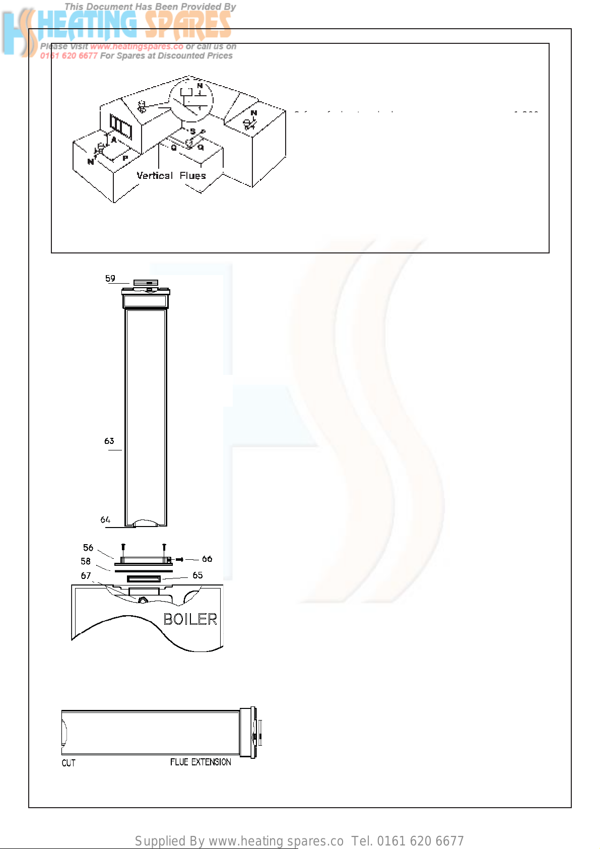
5.7.10 VERTICAL FLUE INSTRUCTION ONLY (Fig.40-41-42)
IN LINE FLUE BEND - 1000 mm MUST BE DEDUCTED FROM OVERALL LENGTH FOR EACH 90° BEND
OBTUSE FLUE BEND -500 mm MUST BE DEDUCTED FROM OVERALL LENGTH FOR EACH 135° BEND
The vertical flue kit is intended for use where
a horizontal flue outlet is not possible or desired.
The vertical flue can be used either with a flat roof
or a pitched roof (maximum pitch 60°).
Where a straight vertical flue is not possible or desired,
an offset vertical flue can be used in conjunction with
a side horizontal flue extension piece and an
inline 135°/90° flue bend (Fig. 41).
IMPORTANT NOTES : For greater flue length see
twin flue or concentric 80/125 flue instructions
Fig. 40
Proceed with installation as detailed in section 5
up to 5.5.8., of the main Installation and Servicing
Instruction, ignoring all references to horizontal flue
installations.
Use adhesive tape to attach the template to the wall,
making sure that the centre line is vertical and that the
flue centre line is virtually below the point at which the
flue will exit the roof.
Fig. 41
L + L = 8m Max
Fig. 42
Straight Flue Straight Flue Offset Flue Offset Flue
L = 12.0 m Max L = 12.0 m Max L = 2.0 m Max L = 2.0 m Max
plus Terminal plus Terminal (10 Bend 90° Max) (20 Bend 45° Max)
plus Terminal plus Terminal
- Ensure that the maximum permissible flue
length is not exceeded (Fig. 42).
- Mark the two wall fixing bracket securing
holes on the wall.
- Detach the template from the wall.
- Use a 10 mm dia. drill to make the 2 holes
securing fixing hanging bracket.
Insert plastic expansion plugs (Fig. 29).
- Screw in the two coach bolts.
- Position the flue extension and fix the
securing screw on the flue adaptor
appliance (Fig. 43) item 66, and ensure
that the gasket is correctly fitted.
Important: Make sure that the flue
extension dia 60 mm duct is inserted fully
into the flue manifold, and the flue manifold
rubber seal is correctly fitted.
Page 24
Supplied By www.heating spares.co Tel. 0161 620 6677
Fig. 42a
Fig.44
Fig.43
POSITION MIN. DISTANCE mm
N above roof level (to base of terminal) 300
P from adjacent wall to flue 300
Q from internal corner to flue 300
S from facing terminal 1,200
S from terminal 600
M horizontally from a vertical terminal to a wall 300
N from an adjacent opening window 1000
Before proceeding with installation check the contents
of the RAVENHEAT VERTICAL FLUE KIT, comprising
of the following pieces:
- 1 RAVENHEAT VERTICAL FLUE
complete with terminal assembly
(for vertical flue application).
- Additional 1000 mm (approx)
Flue Extension pieces as necessary.
Cut a 105 mm diameter hole through the ceiling and/or
roof, at the point previously marked.
Fit a roof flashing sleeve (7 Fig. 43) to the roof, available
from Ravenheat Manufacturing.
Insert the Vertical Flue terminal assembly through the
flashing plate from the outside.
Fix the appliance to the wall, locating onto the Wall
fixing bracket.
Measure the vertical distance between the top of the
flue (Fig. 42a) and the bottom of the flue terminal
assembly (Fig. 41). The measurements should be
taken from the outer diameter of the flue.
NOTE: Where this length does not match any standard
combination of the extensions, extension can be cut to
the required length (Fig. 44).
When cutting both inner and outer ducts of the
extension, always cut on spigot side, and they must
be de-burred.
Starting at the appliance end, assemble the
extension duct sections, making each inner and
outer (flue) joint by inserting the spigot end into the
socket end of the next tube, making sure the seal
rings are correctly located (Fig. 44). Make sure that
the entire flue is adequately supported. Use at least
one bracket for each extension used.
Ensure that all inner flue connections have a good
fit/seal, and that the space clips in each extension
are correctly positioned.
- Position the flue extension and fix the securing
screw on the flue adaptor on the appliance
(Fig. 43) item 66, and ensure that the gasket is
correctly fitted.
Important: Make sure that the flue
extension dia 60 mm duct is inserted fully into the
flue manifold, and the flue manifold rubber seal is
correctly fitted.
5.8 REASSEMBLE BOILER AS PER
(sect. 5.6.1)
5.8.1 Fitting valve pack
24
Remove plastic caps from boiler connection and fit
valves as per Fig. 46 using washers provided.
Page 25

Supplied By www.heating spares.co Tel. 0161 620 6677
5.9 GAS CONNECTION (Fig. 46)
5.13 ELECTRICAL CONNECTIONS
5.9.1 A minimum working gas pressure of 20 mbar
(8 in w.g.) must be available at the boiler inlet
at full flow rate (37 mbar for propane,
29 mbar for butane).
5.9.2 Fit gas service cock to the boiler via the
union nut and connect gas pipe. Do not
overtighten and use another spanner as
a counter force to avoid straining internal
connections.
Important consult (sect 4.5.1).
5.10 CENTRAL HEATING CONNECTION
(Fig. 46)
5.10.1 Before any central heating connections are
made to the boiler all system valves should
be opened and the system thoroughly flushed
out with cold water.
- Connect the central heating return pipe
to the isolating cock.
- Connect the central heating flow pipe to
the isolating cock marked CHF.
- Pipe dimensions and positions are
marked on template supplied and fig. 49a.
5.11 DOMESTIC HOT WATER (Fig. 46)
5.11.1 The domestic hot water circuit does not need
a safety valve but it is essential to ensure
that the pressure of the cold water supply
does not exceed 10 bar. If in doubt it is
advisable to install a pressure reducing valve
The minimum pressure needed to operate
the domestic hot water system is 0.5 bar with
a flow of approx 3 Lts per min. Flush out all
foreign matter from the supply pipe before
connecting to the appliance.
- Connect the 15 mm. cold water pipe to the
stop cock to the appliance inlet.
- Connect the 15 mm. hot water pipe to the
cock to the appliance inlet.
5.12 SAFETY VALVE DISCHARGE
5.13.1 IMPORTANT: Electricity supply must be as
specified in clause (sect. 4.10)
- When controls external to the appliance
are required, design of the external
electrical circuits should be undertaken by a
competent person. In accordance
with the IEE wiring regulations.
It is essential that all external controls
MUST VOLT FREE.
Factory fitted internal wiring must not
be disturbed when wiring external controls.
- To gain access to the electrical box
remove the front panel of the case as
described in clauses sect. 8.1.4 (Fig.54),
remove the two securing screws on the
supporting bracket and lower down ,
unclip the four plastic tabs and lift off the
electrical box cover (Fig.65).
- The terminals are easily visible on the front
of the electronic control board (Fig. 48).
- Heat resistant flexible cable is fitted
between the isolator and the terminal block
A 3 core cable of 0.75 mm
BS 6500.
Make sure all wires to the appliance are
routed away from sharp edges and hot
surfaces.
The cable must be fastened with its cord
anchorage and connected so that should
the cable slip from the anchorage the
current carrying conductors become taut
before the earthing conductor. Securely
tighten all terminal screws and arrange
the cable with slack between the cord
anchorage and the terminal block
WARNING: If the supply cord is damaged,
it must be replaced by a service engineer
(supply cord available from Ravenheat
Manufacturing Ltd).
2
(24x0,2 mm) to
Fig.46
5.12.1 The safety valve is located near the pump.
It has a 15 mm copper to permit a
discharge pipe to be connected.
When connecting ensure the discharge pipe
does not restrict access. The discharge
should terminate facing downward
exterior to the building in a position where
discharging (possibly boiling water & steam)
will not create danger or nuisance, in easily
visible position, and not to cause damage to
electrical components or wiring.
The discharge must not be over an entrance
or a window or any other type of access
25
Page 26

Supplied By www.heating spares.co Tel. 0161 620 6677
5.14 PROGRAMMABLE TIMECLOCK
Instructions for use consult User ’s Guide.
5.15 CONDENSATE DRAIN CONNECTION
5.15.1 The condensate drain connection is between
Gas service cock and Central Heating Flow
valve connections (Fig.49A). An 25mm
plastic overflow pipe is fitted on the
condensing trap and must should be used
to fit on the drain connection, if required,
to discharge condensate to a drain. The
drain pipe should have a fall of a least 2.5°
away from the boiler. Condensate should, if
possible be discharged into the household
internal drainage system.
POSITION OF WATER AND GAS CONNECTIONS
Fig. 49A
If this is not practicable, discharge can be
allowed into the external household drains
or a purpose designed soak away.
It is recommended that any external
condensate drain pipe is insulated and also
preferably of 32 mm diameter, to prevent
freelzing in adverse weather conditions.
The condensate is discharged periodically
in “ slugs” by siphonic action. It is not
necessary to provide air breaks or extra
traps in discharge pipe as there is already a
125mm high trap inside the boiler.
Fitting an extra trap may cause the boiler
siphon to work incorrectly.
Refer to BS5546 or BS6798 for advice on
disposal of boiler condensate.
INSTRUMENT PANEL Fig. 50
26
Page 27

Supplied By www.heating spares.co Tel. 0161 620 6677
SECTION 6 COMMISSIONING
6.1 Each boiler has been through a rigorous
operational procedure at our factory and
should not require any further adjustment
If in the unlikely event of the appliance not
operating correctly, please turn to the Fault
Finding and Logic Sequence charts.
6.2 GAS SUPPLY INSTALLATION
6.2.1 Inspect the entire installation including the
gas meter, test for soundness and purge, all
as described in BS 6891.
6.3 ELECTRICAL INSTALLATION
Preliminary electrical systems checks to
ensure electrical safety shall be carried out
by a competent person (earth continuity,
polarity, resistance to earth). Those checks
are outlined in the «Instructions for British Gas
Multimeter» Booklet. If a fault has occurred
on the appliance the fault finding procedure
should be followed as specified under the
servicing section of this document.
- Continue filling the system until 1.5 bar
register on gauge. Then turn off the filling
points stopcock.
- Inspect the system for water soundness
and remedy any leaks discovered
6.5 SETTING THE SYSTEM DESIGN
PRESSURE
The design pressure must be a min. 1 bar and
max. 1.5 bar. These figures are read off the
pressure gauge.
- The actual reading should ideally be 1
bar + the height in metres to the highest
point of the system above the base of the
appliance (up to max of 1,5 bar).
N.B.: They safety valve is seat to lift a
3 bars (30 mt/42.5 psing).
- To lower the system pressure to the
required value remove drain point
(Fig. 51A) or drain on the heating circuit.
6.6 FILLING THE HOT WATER SYSTEM
Close all hot water draw-off taps.
Open the cold water inlet cock.
Slowly open each draw-off tap until clear
water is discharged.
6.4 INITIAL FILLING OF THE SYSTEM
Open central heating flow and return valves
Unscrew the cap on automatic air release valve
positioned on the top of the pump housing one
full turn (leave open permanently).
- Close all air release taps on the central
heating system.
- Gradually open stopcock at the filling point
connection to the central heating system
until water is heard to flow.
- Starting with the lowest radiator open each
air release tap in turn. Close it only when
clear water, free of bubbles, flows out. In
the same way release air from any high
points in the pipework.
GAS VALVE
Fig. 51
6.7 LIGHTING THE BOILER
Before lighting the boiler make sure that
the heating circuit flow and return valves are
open and also that the cold water input cock
is open.
- If external controls are installed (e.g
timeclock and thermostat) make sure that
they call for heat.
- Push Summer/Winter switch (1A) Fig.50 to
Winter .
IMPORTANT: Before switching on the boiler
POWER SWITCH FOR THE FIRST TIME
when commissioning, turn the heating
control knob (Fig.50) DOWN TO ITS
MINIMUM setting leaving it at minimum for
approx 5 mins to purge air saffely from the
boiler heat exchanger.
Fig. 51A
27
Page 28

Supplied By www.heating spares.co Tel. 0161 620 6677
-Turn control knob 4 (Fig.50) down to
its minimum setting.
-Push the power main switch to on (Fig.50)
-The digital display will show water set point
temperature in central heating .
-The fan start and after a few second the
digital led display will show that the ignition
commence.
-NOTES : It maybe necessary to reset the
Digital Timer on boiler (if fitted) to start.
Put the timer to on position (Fig.50)
-The ignition control will automatically have
three attempts , but initially this may be due
to air in the gas supply line.If the burner fails
to light, the digital led display and fan will
stop, and the display will show
the lockout code.
-If necessary push the boiler Reset
button (Fig.50) and the boiler will
restart automatically.
-After the boiler has light , allow to
warm at minimum temperature setting
to purge any air from the system.
-Once the system has been purged of
air turn the control knob 4 Fig.50 to the
desired position.
With leak detection fluid test for gas
soundness of all gas components and
joints.See paragraph 6.14 for regulating
the heating circuit control knob.
6.8 CHECK THE GAS PRESSURE
Check the gas mains pressure at
at the gas valve test nipple
UPSTREAM ( Fig.51 ) with boiler operating
Check with the Local Gas supplier if the
pressure differ significabntly from 20 mbar
G20 (natural gas), 37 mbar G31 (propane)
and 29 mbar G30 (butane)
IMPORTANT : Any adjustement to the
gas valve should only be carried out by a
qualified person
Refer to table 6.10 adjust the maximum level
of CO
by turning the Throttle on the gas
2
valve ( Fig.51).
Anti-clockwise to increase CO
Clockwise to decrease CO
2
2
After any new regulation wait to stabilise
about one minute.
- Replace the sample point screw on the
flue manifold ( Fig.1 item 8)
- Replace the front panel of the case.
RATIO BETWEEN FAN SPEED AND HEAT INPUT
Fig. 52
ELECTRODES POSITION
Fig. 52B
IMPORTANT :The Gas Valve Throttle
adjuster is required to be sealed with
tamper proof paint after adiustment.
6.9 COMBUSTION CHECK : If a gas carrying
components has been replaced, the
combustion of the appliance should be
checked as follows.
Remove the front panel of the case.
Ensure the boiler and external controls are
calling for heat. Turn on electrical supply.
Open the Hot water tap at maximum flow rate.
Wait at least five minutes or until the unit has
reached its operating temperature.
Unscrew the test sample screw on flue
manifold (Fig.1 item 8 ) Measured the level of
CO
. Check the reading against the
2
corresponding value in sect.3 TECHNICAL
DATA If adjustment proves necessary
then proceed as follows.
28
Once the process of commissioning the boiler
is complete, the commissioning engineer
MUST complete his section in the Benchmark
log book.
Page 29

Supplied By www.heating spares.co Tel. 0161 620 6677
6.10 CHECKING THE FLUE SYSTEM
6.10.1 The flue system should be visually checked for
soundness Check all connections and fixings
are secure and tight
6.11 CHECKING THE HEATING THERMISTOR
6.11.1 Allow the system to warm up and then turn
the C.H thermistor to ensure the main burner
modulates from “high” to “low” and “low” to
“off” and vice versa (scale range
covers approx. 45° C / 85° C).
6.12 TESTING AND REGULATING THE
DOMESTIC HOT WATER SYSTEM FLOW
6.12.1 Put the appliance in summer position with
the (summer/winter) switch (Fig.50).
- Open a domestic hot water tap (preferably
the bath tap). Ensure cold water inlet
stopcock is open and the D.H.W. control
knob (Fig.50) is set at maximum.
- Digital display show water temperature in
demand ( led on)
- If the boiler does not light check that the
water flow rate is above the min. required
to operate the differential pressure 2 8 Lts./
min. (0.61 gals/min).
- The temperature of the water will depend on
the rate at which it flows. If, due to high water
pressure, the flow rate is too high (and thus
the temperature too low for practical use)
the flow rate may be adjusted. It is better to
set for the lowest acceptable temperature,
preferably at the bath tap since the user
can gain higher temperatures at other
restricted flow taps (Table ...)
-If the cold supply is subject to large
fluctuations or is above the permitted max.
water pressure, a suitable pressure/flow
regulator should be fitted in the cold water
supply to the appliance.
- Slowly close the draw off tap to reduce the
flow rate to above the min
(approx. 2.8 litre/min)
- 0.61 gals/min.). Rotate the D.H.W. control
knob to ensure it operates at its various
setting.
- Close the draw-off tap still further. The
burner should stop when the rate falls
below about 2.8 litres/min (0.61 gals/min ).
6.13 HANDING OVER TO THE USER
6.13.1 After completion of installation and
commissioning of the system, the installer
should hand over to the Householder by
taking the following actions:
- Hand the “User’s Instructions” to
the Householder and explain His/Her
responsibilities under the “Gas Safety
Regulations 2000”.
- Explain and demonstrate the lighting and
shutting down procedures.
- The operation of the boiler including
the use and adjustment of ALL system
controls which should be fully explained
to the Householder. This then ensures the
greatest possible fuel economy consistent
with household requirements of both
heating and hot water consumptions.
Advise the User of the precautions
necessary to prevent damage to the
system, and to the building, in the event
of the system remaining inoperative
during frost conditions
- Explain the function and the use of the
bo
iler switch Summer/W inter and
ON/OFF switch,reset and digit display .
- Explain and demonstrate the function of
temperature controls, neon lights radiator
valves etc for the economic use of the
system.
- If an optional time clock is fitted, then
draw attention to the time clock User’s
Instructions and hand them to the
Householder
- Stress importance of regular servicing by
a qualified Heating Engineer and that a
comprehensive service should be carried
out AT LEAST ONCE A YEAR
- Fill in the Benchmark log book and leave
completed with the customer.
SECTION 7 SERVICING INSTRUCTIONS
Ravenheat are a member of the Benchmark initiative
and fully supports the aims of the programme.
Benchmark has instructed to improve the standards
of installation and commissioning of central heating
systems in the UK and to encourage in the regular
servicing of all central heating systems to ensure
safety and efficiency.
Range Rating regulation of Central Heating
Maximum Setting
C.H. Regulations
minimum Setting
Heat Input Fan speed
kW Hz
HE150 HE120 HE 150 HE120
Maximum Setting 32.0 26.0 180 175
minimum Setting 8.3 5.78 53 47
29
Page 30

Supplied By www.heating spares.co Tel. 0161 620 6677
7.1 SERVICING
7.1.1 To ensure continued efficient operation of
the appliance it is necessary to carry out
servicing and cleaning at regular intervals.
The frequency of cleaning will depend upon
the particular installation conditions and
usage but in general, once year should be
adequate.
WARNING
Before the start of any servicing or
replacement of components always
isolate electricity supply to the appliance
and always turn off the appliance gas
supply at the gas service cock.
Data badge position-lower left hand front panel.
- The following notes apply to the appliance
and its controls but it should be remembered
that attention must also be paid to the
heating and hot water circuits with special
attention to radiator valves, thermostats,
clocks, leaking hot water taps etc.
- Where it is necessary to replace a gasket
that relies on adhesive for securing - this
adhesive will be supplied with the gasket
as a spare item.
- In all cases prior to servicing, remove
the front panel of the case.Operate the
appliance by turning the hot water services
on to a high water flow, measurement of the
products of combustion can be achieved
by connection of a probe to the combustion
analyser test point.
- IMPORTANT: After completing any
servicing or replacement of gas carrying
components it is essential that a test for
gas soundness is always carried out along
with functional checks in operation
Fig.53
7.2 TO INSPECT AND CLEAN THE
APPLIANCE
7.2.1 Before carrying out cleaning operation,
cover the electrical control panel with a
piece of waterproof material to protect it
from debris.
7.2.2 Drop down the control panel into the
service position
Unscrew the gas valve from gas pipe
inlet. Disconnect the gas valve electrical
plug at the gas valve.
Disconnect the electrical plug leads from
the fan.
Disconnect the electrode leads from the
electrodes
Remove the five combustion chamber
retaining nuts and gently remove the
fan,gas control valve, electrodes and
burner assembly from the combustion
chamber.(Fig.53)
30
7.2.3 Inspect the heat exchanger for any
blockage. Deposits of any material should
be brushed away using a soft brush.
NOTE: Do not use brushes with metallic
bristles
7.2.4 Examine internal pipe-work connections
and automatic air vent for any water leaks
Rectify if necessary
7.2.5 Examine and remove loose debris from
combustion chamber using a soft brush
and vacuum cleaner. Carefully flush by
spraying water any remaining debris
through the condensate trap.(Ensure
the water is kept away from electrical
components)
Page 31

Supplied By www.heating spares.co Tel. 0161 620 6677
7.2.6 Inspect the siphonic condensate trap for
a blockage.
Remove the cap at the base of the
condensate trap.
Remove any solid found.
Remove the float to clean it.
Any deposits should be flushed out.
Reassemble and refit the condensing
trap.
When refitting the cap ensure that a
watertight seal is achieved, but do not
use excessive force
7.2.7 Examine the spark and sensing electrodes
for any mechanical damage, Clean away
any debris and check the spark and sensing
gap. See Fig.52B
7.2.8 Examine flue duct and flue manifold
and ensure that there is no obstruction.
Examine the gasket at the entry into the
flue manifold.
7.2.9 It is essential that a good seal is made at
the outlet to the flue manifold, renew this
gasket if there is any sign of damage
or deterioration.
8.2 TO REMOVE/REPLACE IGNITION
CONTROL BOARD
8.2.1 Remove the front casing panel
(sect. 8.1.4).
8.2.2 Detach all the connectors from the
ingition control board.
8.2.3 Remove the 2 screws that secure the
Ignition control board to the depression
chamber, and remove.
8.2.4 Replace in reverse order
Fig.54
SECTION 8 REPLACEMENT OF PARTS
8.1 GENERAL
8.1.1 Replacement of parts must be carried
out by a competent person.
8.1.2 Before replacing any parts the boiler
should be isolated from the mains electric
supply and the gas should be turned off at
the service cock on the boiler.
8.1.3 After replacing any parts always test for
gas soundness and if necessary carry out
functional test of the controls.
8.1.4 For replacement of parts, the front,side and
bottom panel panels of the boiler will need to
be removed.
To remove the front panel unscrew the two
screws upper and the two screws lower that
securing the front panel to the boiler and
lift off .
To remove the bottom panel unscrew the
four screws and lift off.
To remove the side panels ,
remove the front and bottom panels,
unscrews the four screw upper, the two lower
and the two screw in front and lift off. (Fig.54)
31
Page 32

Supplied By www.heating spares.co Tel. 0161 620 6677
8.3 TO REMOVE/ REPLACE THE
ELECTRODES (Fig.55)
8.3.1 Remove the front casing panel (sect. 8.1.4).
8.3.2 Remove the ignition and/or sensing lead
plug .
8.3.3 Unscrew the two securing screws and put
them into a container so that they don’t get
lost.
Withdraw the Spark electrode and /or
Sensing electrode carefully from the
combustion chamber cover being
careful not to damage the seal.
8.3.4 Replace with new electrode in reverse
order. Ensure gap is correct and there
is a good seal when replaced.
8.4 TO REMOVE/REPLACE THE FAN
(Fig. 56-56A)
8.4.1 Remove front and left hand side panel of
the case (sect. 8.1.4).
8.4.2 Unplug plastic plug from the DC fan supply
8.4.3 Unscrews the four screws that securing fan
to the gas manifold, check the gasket and
replace if necessary.
Fig.55
Fig.56A
8.4.4 Reassemble in reverse order. Ensure wires
are connected correctly
Fig.56
32
Page 33

Supplied By www.heating spares.co Tel. 0161 620 6677
8.5 TO REMOVE/REPLACE THE BURNER
(FIG.57)
8.5.1 Remove front casing (sect. 8.1.4).
8.5.2 Unscrew and Gently Remove combustion
chamber cover assembly with gas valve,
fan ,burner and electrodes from combustion
chamber.as in sect. 7.2.2
8.5.3 Remove the four screws that secure the gas
manifold and carefully pull out the burner.
IMPORTANT: THE BURNER WILL REQUIRE
A NEW GASKET WHEN REFITTED.
8.5.4 Replace in reverse order
Fig.57
8.6 TO REMOVE/REPLACE THE HEAT
EXCHANGER
8.6.1 Remove front casing (sect 8.1.4).
8.6.2 Unscrew and Gently Remove combustion
chamber cover assembly with gas valve,
fan ,burner and electrodes from combustion
chamber as in sect. 7.2.2.
8.6.3 Drain the boiler CH circuit and
drain the DHW circuit .
8.6.4 Remove the clip securing the condense
pipe out of the bottom of the heat
exchanger and pull for to remove the pipe
8.6.5 Remove the clips securing the flow and
return pipes at the heat exchanger.
8.6.6 Unscrews the two nuts that fix the pipes at
diverter valve and pump and move away
from the heat exchanger.
8.6.7 Loosen the three heat exchanger securing
screws and clamps remove the heat
exchanger.
CAUTION : There will be water in the heat
exchanger
8.6.8 Carefully ease heat exchanger out.
Replace in reverse order, always use a new
oring seals.
8.7 TO REMOVE/REPLACE THE IGNITION
CONTROL BOX .
8.7.1 Remove front casing (sect 8.1.4).
8.7.2 Remove ignition and sensing leads and
electrical connections.
8.7.3 Remove the two fixing screws that fasten
the ignition control box at the depression
chamber.
8.7.4 Replace in reverse order.
Ensure correct wire position.
33
Page 34

Supplied By www.heating spares.co Tel. 0161 620 6677
8.8 TO REMOVE/REPLACE GAS CONTROL
VALVE AND OR VENTURI PLATE .
(Fig.58).
8.8.1 Remove front casing (sect 8.1.4).
8.8.5 Unscrew and Gently Remove combustion
chamber cover assembly with gas
valve, fan ,burner and electrodes from
combustion chamber.as in sect. 7.2.2
8.8.2 Drop down the control panel into the
service position.
8.8.3 Unplug plastic plug from the DC fan
supply and unscrew the gas valve from
gas pipe inlet
8.8.4 Remove the electrical plug from the gas
control valve.
Check the position of the gas valve on the
fan
Fig.58
8.8.6 Remove the three screws, which fix the
gas valve and venturi plate at the fan
8.8.7 Remove the gas valve
8.8.8 Replace in reverse order.
8.8.9 IMPORTANT : When gas control valve
will be re -fitting,
check combustion CO
adjusted if necessary
see section 6.10
and
2
8.9 TO REMOVE/REPLACE COMBUSTION
CHAMBER FRONT INSULATION
(Fig.60).
8.9.1 Remove front casing (sect 8.1.4).
8.9.2 Remove fan,gas valve and burner
assembly as in sect.7.2.2.
8.9.3 Remove burner and spark/sensing
electrodes and replace in reverse order
NOTE: THE BURNER WILL REQUIRE
A NEW GASKET.
8.10 TO REMOVE/REPLACE COMBUSTION
CHAMBER REAR INSULATION .
8.10.1 Remove front casing (sect 8.1.4).
8.10.2 Remove fan,gas valve and burner
assembly as in sect.7.2.2.
34
8.10.3 Remove securing screw and washer
in the center of the insulation and
withdraw insulation.
8.10.4 Reassemble in reverse order.
8.11 TO REMOVE/REPLACE VIEWING
GLASS. (Fig.61).
8.11.1 For access ref. sect. 8.9 (fig60).
8.11.2 Remove the two screw that securing view
glass bracket
8.11.3 Remove view glass .
8.11.4 Remove gasket .
8.11.5 Replace in reverse order.
Page 35
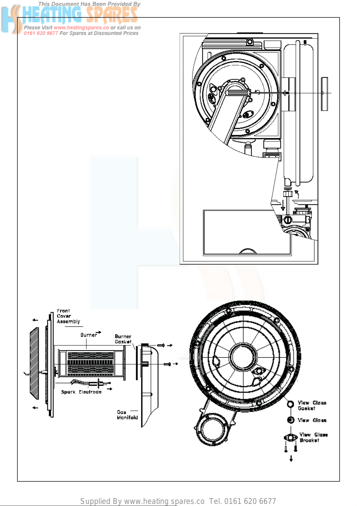
Supplied By www.heating spares.co Tel. 0161 620 6677
8.12 TO REMOVE/REPLACE EXPANSION
VESSEL (Fig.59).
8.12.1 Remove front casing (sect 8.1.4).
8.12.2 Drain the CH circuit
8.12.3 Remove at the front the securing bracket.
8.12.4 Unscrew the nut that fix the expasion
vessel, and carefully lift the vessel up and
remove.
8.12.5 Replace in reverse order.
NOTE: Always use new gasket
and “O”rings.
8.13 TO REMOVE/REPLACE PLATE TO PLATE
HEAT EXCHANGER .
8.13.1 Remove front casing (sect 8.1.4).
8.13.2 Close off on/off valves for CH circuit and
DHW circuit and drain the boiler and drain
hot water from the lowest hot water tap
.
8.13.3 Unscrews the two srews that connect the
DHW heat exchanger and pull it out from
the boiler.
Fig.59
8.13.4 If necessary the pipes from the flow
manifold may have to be remove for easier
access.
8.13.5 Replace in reverse order.
NOTE: Always use new “O”rings.
Fig.60
Fig.61
35
Page 36

Supplied By www.heating spares.co Tel. 0161 620 6677
8.14 TO REMOVE/REPLACE FLUE
MANIFOLD .
8.14.1 Remove front casing (sect 8.1).
8.14.2 Unscrew and Gently Remove combustion
8.14.3 Remove the heat exchanger as sect. 8.6.
8.14.4 Remove the two securing screws and pull
8.14.5 Replace in reverse order.
NOTE: Always check the flue oring seal.
8.15 TO REMOVE/REPLACE DIVERTER
8.15.1 Remove front casing (sect 8.1).
chamber cover assembly with gas valve,
fan ,burner and electrodes from combustion
chamber.as in sect. 7.2.2
to remove the flue manifold.
VALVE SWITCH .
8.17 TO REMOVE/REPLACE DIVERTER
VALVE.
8.17.1 Remove front casing (sect 8.1).
8.17.2 Close the on/off valves for the heating
circuit and the hot water circuit.
Drain the boiler at drain point on the pump
manifold and drain hot water from the
lowest hot water tap .
8.17.3 Remove diverter valve switch (sect.8.15).
8.17.4 Unscrew the diverter valve four nuts and
pull it out from boiler.
8.17.5 Replace in reverse order.
NOTE: Always use new seals.
8.17.6 Fill the boiler as described in sect.6.4 and
check for leasks.
8.15.2 Detach the electrical plug and remove the
retaining clip.
8.16 TO REMOVE/REPLACE PUMP (Fig.62).
8.16.1 Remove front casing (sect 8.1).
8.16.2 Remove lower grill of the casing and lower
the instrument panel with the electrical
box.
8.16.3 Detach the supply wire connector from the
pump.
8.16.4 Remove the securing clip at the pump
manifold.
8.16.5 Remove the securing clip the fastens
the pressure gauge probe and expansion
vessel pipe to the pump.
8.16.6 Unscrew the nut at the expansion vessel
and remove the pipe.
8.16.7 Unscrew the nut that fastens the pump
to the CH pipe and remove the pump.
8.16.8 Replace in reverse order.
NOTE : Alway use new seals when re-
fitting new pump.
Fig.62
8.18 TO REMOVE/REPLACE THE CENTRAL
HEATING AND/OR DOMESTIC HOT
WATER THERMISTOR (Fig.63).
8.18.1 Remove front casing (sect 8.1)and lower
the instrument panel .
8.18.2 Remove the wires that connect the
8.18.3 Remove the retainig clip from the pipe.
NOTE: When reconneting the polarity
of the wiring to thermistor is unimportant.
8.18.4 Replace in reverse order.
36
thermistor.
Page 37

Supplied By www.heating spares.co Tel. 0161 620 6677
8.19 TO REMOVE/REPLACE OVERHEAT
THERMOSTAT (Fig.63).
8.19.1 Remove front casing (sect 8.1.4)
8.19.2 Remove the two wires that connect to the
overheat thermostat.
8.19.3 Remove the two screws securing the
thermostat to the pipe and pull it out.
8.19.4 Replace in reverse order
8.20 TO REMOVE/REPLACE AUTOMATIC AIR
VENT (Fig.64).
8.20.1 For access ,remove front casing (sect 8.1.4).
8.20.2 Close the on/off valves for central Heating
circuit and drain the water from the boiler.
8.20.3 Remove the pump see sect.8.16 .
8.20.4 Remove the retainig clip .
8.20.5 Pull the automatic air vent from the pump.
8.20.6 Replace in reverse order and check for leak.
NOTE: Fit a new “O” ring
8.21 TO REMOVE/REPLACE LOW WATER
PRESSURE SWITCH ( Fig.64A) .
Fig.63
Fig.64
8.21.1 Remove front casing (sect 8.1.4).
8.21.2 Close the on/off valves for central Heating
circuit and drain the water from the boiler.
8.21.3 Pull wires off and unscrew the low water
pressure switch from pump manifold.
8.21.4 Replace in reverse order, fill the system as
described in sect.6.4 and check for leaks.
NOTE: Polarity of the wires is important
8.22 TO REMOVE/REPLACE SAFETY
DISCHARGE VALVE .
8.22.1 Remove front casing (sect 8.1).
8.22.2 Close the on/off valves for central Heating
circuit and drain the water from the boiler.
8.22.3 Unscrew the screw below the valve.
8.22.4 Remove the securing clip and remove the
pipe. Detach the valve.
8.22.3 Replace in reverse order, use a fill the system
as described in sect.6.4 and check for leaks.
Fig.64A
37
Page 38

Supplied By www.heating spares.co Tel. 0161 620 6677
8.23 TO REMOVE/REPLACE TIMECLOCK
8.23.1 Remove front casing (sect 8.1.4)
and lower the instrument panel .
8.23.2 Remove control board box cover.
8.23.3 Pull the two securing clip that fasten the
timeclock to the panel instrument,
and pull it out .
8.24 TO REMOVE/REPLACE CONTROL
BOARD (Fig.65).
8.24.1 Remove front casing (sect 8.1.4)
and lower the instrument panel .
8.24.2 Remove control board box cover.
(sect.8.13.1).
8.24.3 Detach the connectors from the board .
8.23.4 Carefully remove the four wires
connecting timer by pulling spade
connectors from timer
8.23.5 Replace in reverse order
NOTE: Ensure all electrical connections
are made correctly.
8.24.4 Detach the PCB board from its base by
unscrewing the four securing screws.
8.24.5 Replace in reverse order.
NOTE: When refitting the control panel
ensure the leads are not trapped.
8.25 TO REMOVE/REPLACE DIGITAL
DISPLAY BOARD (Fig.65).
8.25.1 Remove front casing (sect 8.1.4)
and lower the instrument panel .
8.25.2 Remove control board box cover.
8.25.3 Detach the connectors from the board.
8.25.4 Detach the Digital Display board from
panel instruments by unscrewing the four
securing screws.
8.25.5 Replace in reverse order.
Fig.65
38
Page 39

Supplied By www.heating spares.co Tel. 0161 620 6677
8.26 TO REMOVE/REPLACE CONDENSING
TRAP (Fig.66).
8.28 TO REMOVE/REPLACE THE WATER
PRESSURE GAUGE (Fig. 67).
8.26.1 Remove the casing (sect 8.1.4) and lower
the instrument panel .
8.26.2 Remove the securing clip and pull out the
plastic pipe that connect the condensing
trap at the heat exchanger.
8.26.3 Unscrew the nut that fasten the
condensing trap to the depression
chamber and remove it.
8.26.4 Replace in reverse order
8.28.1 Remove front casing (sect 8.1.4) lower
the instrument panel and remove
lower panel of the case.
8.28.2 Close the heating system on/off valves
and drain the water from the drain point
on the heating system .
8.28.3 Remove the retaining clip that secures the
pressure gauge probe.
8.28.4 Remove the pressure gauge from the
instrument panel by pressing its fastening
springs.
8.28.5 Replace in reverse order.
Fig.66
8.27 TO REMOVE/REPLACE THE MAIN
SWITCH (Fig. 67).
8.27.1 Remove front casing (sect 8.1.4) and lower
the instrument panel .
8.27.2 Remove the control box cover.
8.27.3 Pull off the switch knob. Remove
the switch out from the instrument panel
by pressing the clamp springs .
8.27.4 Detach the wires that connect to the
switch, make sure that these wires are
later reconnected to the same poles .
8.27.5 Replace in reverse order
Fig.67
39
Page 40

Supplied By www.heating spares.co Tel. 0161 620 6677
SECTION 9
FAULT FINDING CENTRAL HEATING
Before trying to operate the boiler make sure that:
- All gas supply cocks are open and the gas supply has been purge of air.
- The heating system pressure is at least 1 bar min to 1.5 bar Max.
- Main Switch on
- Select “Winter”
- Central Heating control knob to maximum
- Ensure external controls calling for heat (Room stat/Timeclock/TRV)
Does heating LCD
on digital display
illuminate
Yes
Does the pump run
Yes
Is the burner LCD
illuminate on
digital display
Yes
No
No
No
Is 230 at L-N
connections on
control board
Yes
Is low pressure
in the system
Yes
Re-pressure the
system
Is 17 displayed
No
Is 01 displayed
No
Is 28 displayed
No
Is 12 displayed
No
Is 04 displayed
Check/Replace
No
Replace On/Off Switch
No
Is there continuity at
summer/winter switch
Yes
Yes
Yes
Yes
Yes
external Fuse and
supply
Is 230V at pump
No
Yes
FAILED FAN SEQUENCE
- Check Fan Voltage
FAILED IGNITION SEQUENCE
- Check condensate drain if is not blocked
- Check gas valve operation
- Check the fan starts
- Check Ignition control board and cables
FAILED LOW WATER PRESSURE SWITCH
- Check /Replace Low water pressure switch
- Check system pressure
FAILED HEATING SENSOR
- Check / Replace heating sensor
FAILED OVERHEAT
- Check / Replace heating sensor
- Check the overheat thermostat
Yes
No
Check/Replace
pump if necessary
Replace
summer/winter switch
Check /Replace Timeclock
if OK Replace control board
Does boiler go off
before set point
No
- Check Domestic Hot Water
Yes
- Check if the system has been purge of air
- Check / Replace Automatic air vent
NOTE : See Section 10 for LED DISPLAY CODE
40
RESET THE BOILER
- Push the Reset button on Digital Display and
check LCD if illuminate
Page 41

Supplied By www.heating spares.co Tel. 0161 620 6677
FAULT FINDING DOMESTIC HOT WATER
Before continuing it may be necessary to see Central Heating Fault Finding (Sect.9)
- All gas supply cocks are open and the gas supply has been purge of air.
- The heating system pressure is at least 1 bar min to 1.5 bar Max.
- Main Switch on
- Select “Summer” (Fig.50 item 1A)
- Domestic Hot Water control knob to maximum
- Open Domestic hot tap close to the appliance
Ensure Domestic
Hot Water fl ow is
min. of 3 l/min
Yes
Does DHW LCD
on digital display
illuminate
Yes
Does the burner
LCD illuminate on
digital display
No
No
No
Check fi lters are
clean
Is low pressure
in the system
Yes
Re-pressure the
system
Is 06 displayed
No
Is 12 displayed
No
Yes
Yes
Check Microswitch
on shunt valve
being operate
mechanically
No
Check/Replace
diverter valve
FAILED DHW SENSOR
- Check /Replace DHW sensor and cables
FAILED HEATING SENSOR
- Check / Replace heating sensor
Yes
Check/Replace
diverter valve
Yes
Does the DHW
temperature
stabilise at set point
Yes
END OF DOMESTIC HOT WATER TEST
No
No
Is 28 displayed
Check / Replace DHW potentiometer
Yes
NOTE : See Section 10 for LED DISPLAY CODE
FAILED LOW WATER PRESSURE SWITCH
- Check /Replace Low water pressure switch
- Check system pressure
RESET THE BOILER
- Push the Reset button on Digital Display and
check LCD if illuminate
No
Check / Replace DHW sensor
41
Page 42

Supplied By www.heating spares.co Tel. 0161 620 6677
SECTION 10 ELECTRICAL SYSTEM DIAGRAM
Fig. 94
CASE OFF
CASE OFF
CASE OFF
42
Page 43

Supplied By www.heating spares.co Tel. 0161 620 6677
SECTION 11 INSTALLATION INSTRUCTIONS FOR ALTERNATIVE FLUE SYSTEM
11.1 INSTALLATION INSTRUCTIONS FOR TWIN FLUE PIPE (ECCENTRIC FLUE DUCT SYSTEM)
Part. No Description
0019SDO11005/0 Twin fl ue header F80/F80
0019PRO11020/0 Straight pipe L.1000 d80
0019CUR11015/0 90° Elbow d80
0019CUR11020/0 45° Elbow d80
0019GRI11005/0 Air inlet terminal d80
0019GRI11010/0 Exhaust terminal d80
0019TER06011/0 Vertical eccentric fl ue Terminal
11.1.1 TWIN FLUE INSTRUCTIONS
This part of the installation manual covers the
installation and fi xing instructions of the twin
Fig. 95
IMPORTANT :Please,
lubricate the internal
part of the seals before
being fitted.
IMPORTANT
These instructions must be read in
conjunction with the main installation and
servicing instructions
As with all fl ues the kits must be installed
taking due account of the current issue of BS
5440 parts 1 & 2 and timber frame housing
REF DM2
Also note that the requirements will vary
depending upon the kit being installed.
Guidance is provided but unless otherwise
stated, always comply with the
recommendations of the relevant codes of
practice
fl ue eccentric fl ue duct systems only
When ordering twin fl ue it must be stated for
CSI LOW NOX range.
Typical installation procedures are illustrated
by drawings
Before fi xing the twin fl ue system the existing
Remove the front panel of the case(sect.8.1)
Unscrew the screw (Fig.31 item 66) on the
Flue adapter.
Make sure that the Flue manifold rubber seal
is locate into the fl ue manifold, and lubricate
the internal part of the seal before assembly.
(see sect. 4.6)
Locate the header gasket on the twin fl ue
header and push into the Flue adaptor
(Fig.31 item 56) making sure that the inner
plastic exhaust locates fi rmly in the outlet
spigot of the fl ue manifold, and screw
the securing screw that secure the twin fl ue
header on the boiler.
Locate the 2 x 80 mm ‘O’ rings in the twin
flue header and lubricate the internal part of
the seal before assembly to ensure easy
snug fi t.(see sect. 4.6)
Figures show the versatility of this flueing
system. Measurements and bends must be
calculated correctly so as not to oversize
maximum flue lengths.
All located ‘O’ rings must be lubricated with
a silicone grease to ensure easy, snug fit.
NOTE: Exhaust flue must slope 2.5° down
towards the boiler 45 mm/m fall per metre of
flue length.
Spacing Clips
Spacing Clips are available on request should
they be required.
NOTE: for eccentric vertical flue a 125 mm
(5 in) diameter flashing plate will be required.
43
Page 44

Supplied By www.heating spares.co Tel. 0161 620 6677
IMPORTANT:
- See Fig. 6 and 42 for terminal clearances.
- The pressure loss see table 6.
IMPORTANT NOTICE:
- inlet and exhaust terminals must never
be installed on opposite walls of the building (PrEN 483).
- If the fl ue terminates less than 2 m above a balcony, above
the ground, or above a fl at roof to which people have access,
then a suitable terminal guard must be fi tted.
- Fit only recommended fl ue terminal guard by
securing concentrically around terminal with screws.
11.1.2
11.1.3
Fig. 96
Exhaust/suction system with two separate rated 80 dia.
Pipes - exhaust on fl at or sloping roof,
suction from vertical wall ( Fig.96 ).
Maximum distance D = L + L1 = 40.5 metre + Terminal
Minimum total length = 2 metre
NOTE: Exhaust fl ue must slope 2° down towards the
boiler 35 mm fall per metre.
Exhaust/suction system with concentric pipes for fl at or
sloping roofs. Extensions with two separate pipes
( Fig.95 ).
Maximum distance : T= L = 21+21 = 42 metre+Terminal
Minimum distance : L = 0.5+0.5=1metre + Terminal
Exhaust terminal must not be cut
NOTE:
- If bends are used in the exhaust fl ue then horizontal
- sections must be avoided and there must be a 2° slope
- towards the boiler 35 mm fall per metre.
Fig. 97
IMPORTANT :Please,
lubricate the internal
part of the seals before
being fitted.
11.1.4
Exhaust/suction system with two separate
pipes through a single vertical wall ( Fig.97 ).
Maximum distance : D = L + L1 = 37 metre
Minimum distance : D = L + L1 = 1 metre
Min distance between pipe 50 mm.
44
Available on request from:
RAVENHEAT MANUFACTURING LTD
Chartist Way,Morley, Leeds, West Yorkshire
ENGLAND LS27 9ET - U.K.
Tel. 0044(0) 113 252 7007
Page 45

Supplied By www.heating spares.co Tel. 0161 620 6677
11.2 INSTALLATION INSTRUCTIONS FOR CONCENTRIC 80/125 FLUE SYSTEM
11.2.1 The vertical 80/125flue kit is intended for use
where a horizontal 60/100
flue outlet is not possible or desired.
The vertical flue can be used either with
a flat roof or a pitched roof (maximum pitch 60°).
Where a straight vertical flue is not possible or
desired, an offset vertical flue can be used in
conjunction with a side horizontal flue extension
piece and an inline 135°/90° flue bend (Fig. 99).
IMPORTANT:
- See Fig. 98 and 99 for terminal clearances.
- The pressure loss see table 6.
IMPORTANT NOTICE:
- When using our vertical fl ue kit the 125mm x 100 reducer is
supplied complete with the vertical terminal simply remove this
and fi x it into the fl ue adaptor on the top of the boiler
Fig. 98
Fig. 99
L + L = 23.5m Max
Straight Flue Straight Flue 90° Offset Flue 135° Offset Flue
L = 25 m Max L = 25 m Max L = 21.0 m Max L = 22.5 m Max
plus Terminal plus Terminal plus Terminal plus Terminal
NOTE : If using Flue arrangement in Fig.99 then the 125x100 Flue reducer
must be purchased separately
Part No Description
0019PRO11030/0 Flue Extension 80/125 L1000
0019PRO11025/0 Flue Extension 80/125 L500
0019RID11005/0 125/80 to 100/60 Flue reducer
0019CUR11025/0 45° Flue bend 80/125
0019CUR11030/0 90° Flue bend 80/125
0019TER01005/0 Horizontal Flue Terminal 80/125
0019TER11010/0 Vertical Flue Terminal 80/125
0019TEG06005/0 Flashing sleave
IMPORTANT :Please,
lubricate the internal
part of the seals before
being fitted.
Available on request from:
RAVENHEAT MANUFACTURING LTD
Chartist Way,Morley, Leeds, West Yorkshire
ENGLAND LS27 9ET - U.K.
Tel. 0044(0) 113 252 7007
45
Page 46

Supplied By www.heating spares.co Tel. 0161 620 6677
SECTION 12
17
SPARE PARTS
16
15
7
24
10 21
9
4
25
1
29
28
42
14
12
43
31
22
33
32
13
6
18
11
30
3
27
19
2
4
20
41
8
26
46
44
23
Page 47

Supplied By www.heating spares.co Tel. 0161 620 6677
RAVENHEAT HEI 120/150 (T) LOW NOX
HIGHT EFFINCENCY CONDENSING COMBINATION BOILER
SHORT LIST OF SPARE PARTS
Ravenheat G.C.
Pos. Part. No. Part. No. Description
1 0014PAN11005/0 Instrument panel
2 0012INT09010/0 Main - Summer/Winter switch
3 0012POT11005/0 DHW / CH Potentiometer assembly
4 0007TER08010/0 Overheat thermostat
5 0006IDR11005/0 Water pressure gauge
6 0007TER05006/0 DHW / CH Sensor
7 0014VET11005/0 Sight glass
8 0012TRA11010/0 AC/DC Fan Supply
9 0012GEN11005/0 Ignition control board
10 0008VAL11005/0 Dungs Gas control valve CSI 120
10.1 0008VAL11015/0 Dungs Gas control valve CSI 150
11 0012CAN11005/0 Ignition electrode
12 0012CAN11010/0 Sensing electrode
13 0012CAV11005/0 Cable for Spark electrode
14 0002SCA11010/0 Cable for Sensing electrode
15 0002SCA11010/0 Heat exchanger CSI120
15.1 0002SCA11015/0 Heat exchanger CSI150
16 0002COP11005/0 Heat Exchanger cover assembly
17 0012VEN11005/0 Fan
18 0012CIR11015/0 Modulating Control Board
19 0012CIR11020/0 Digital Display Board
20 0014RAC11005/0 Condensing trap
21 0009CIR11005/0 Circulation pump
22 0008VAL11010/0 Air purge valve
23 0008VAL01018/1 Safety relief valve (3 bar)
24 0002COL11005/0 Flue gas exhaust Manifold
25 0003BRU11005/0 CSI120 Burner
25 0003BRU11010/0 CSI150 Burner
26 0011GRU11010/0 Flow return
27 0005PRE05010/0 Low water pressure switch
28 0004VAS11011/0 Expansion tank
47
Page 48

Supplied By www.heating spares.co Tel. 0161 620 6677
Ravenheat G.C.
Pos. Part. No. Part. No. Description
29 0002SCA09030/0 Heat exchanger for D.H.W. CSI120
29.1 0002SCA09025/0 Heat exchanger for D.H.W. CSI150
30 0012ORO01010/0 Digital Timer
32 0012FUS01010/0 Internal fuse 315mA
33 0012FUS01015/0 Internal fuse 3.15A
34 0013ORI11030/0 DHW Heat exchanger O”ring”
35 0013ORI11005/0 Valv. gas / Mixer O”ring”
36 0013ORI11010/0 Pump / Manifold O”ring”
37 0013ORI11015/0 Pump / press.gauge O”ring”
38 0013ORI11020/0 Pump / Exp. vassel O”ring”
39 0013ORI11025/0 Heat exchanger O”ring”
40 0019FLA11005/0 Flue Adaptor
41 0011GRU11005/0 Flow manifold
42 0012RIV11005/0 Flow detector
43 0012MOT11005/0 Diverter valve switch
44 0007TER05005/0 DHW sensor
48
Page 49

Supplied By www.heating spares.co Tel. 0161 620 6677
Chartists Way, Morley, Leeds, LS27 9ET
Telephone : 0044(0)113 252 7007
Tfax : 0044(0)113 238 0229
Website : www.ravenheat.co.uk
E-mail : sales@ravenheat.co.uk
Ravenheat reserves the right to make changes and
improvements in our products which may affect the accuracy
of the information contained in thi leafl et.
COD 0017LIB11011/0 - 10/2006 Rev.1
Page 50

Supplied By www.heating spares.co Tel. 0161 620 6677
The code of practice for the installation, commissioning & servicing of gas central heating
Installation, Commissioning and Service Record Log Book
CUSTOMER DETAILS
NAME
ADDRESS
IMPORTANT
1. Please keep the Log Book in a safe place for future reference.
2. This Log Book is to be completed in full by the competent person(s) who commissioned the boiler and associated equipment and then handed to
the customer. When this is done, the Log Book is a commissioning certifi cate that can be accepted as evidence of compliance with the appropriate
Building Regulations.
3. Failure to install and commission this appliance to the manufacturer’s instructions may invalidate the warranty.The above does not affect your statutory rights.
INSTALLER & COMMISSIONING ENGINEER DETAILS
INSTALLER DETAILS
COMPANY NAME
ADDRESS
INSTALLER’S NAME
CORGI REGISTRATION DETAILS
NAME
ADDRESS
CORGI REGISTRATION DETAILS
REG No.
COMMISSIONING ENGINEER
REG No.
(IF DIFFERENT)
BOILER
MAKE AND MODEL
APPLIANCE SERIAL No.
LOCATION
LOCATION
CONTROLS
To comply with the Building Regulations, each section must have a tick in one or other of the boxes.
REQUIREMENT MEASURES PROVIDED
1. TIME AND TEMPERATURE CONTROL TO HEATING ROOM STAT & PROGRAMMER/TIMER PROGRAMMABLE ROOMSTAT
TEL No.
CORGI ID SERIAL No.
CORGI ID SERIAL No.
NEW SISTEM
INSTALLATION DATE
TEL No.
COMMISSIONING DATE
TEL No.
SEDBUK No. %
or REPLACEMENT BOILER
%
2. TIME AND TEMPERATURE CONTROL TO HOT WATER CYLINDER STAT & PROGRAMMER/TIMER COMBI BOILER
3. HEATING ZONE VALVES FITTED NOT REQUIRED
4. THERMOSTATIC RADIATOR VALVES FITTED
5. AUTOMATIC BYPASS TO SYSTEM FITTED NOT REQUIRED
6. BOILER INTERLOCK PROVIDED
PLEASE FOLLOW THE INSTALLATION AND COMMISSIONING INSTRUCTIONS IN THE INSTALLATION MANUAL SUPPLIED WITH THE EQUIPMENT
FOR ALL BOILERS
HAS THE SYSTEM BEEN FLUSHED IN ACCORDANCE
WITH THE BOILER MANUFACTURER’S INSTRUCTIONS?
HAS AN INHIBITOR BEEN USED?
WHICH INHIBITOR WAS USED?
YES
NO
WHAT WAS THE CLEANSER USED?
YES
NO
For the central heating mode, measure and record:
HEAT INPUT
BURNER OPERATING PRESSURE
CENTRAL HEATING FLOW TEMPERATURE
CENTRAL HEATING RETURN TEMPERATURE
kW
mbar
°C
°C
FOR COMBINATION BOILERS ONLY
HAS A WATER SCALE REDUCER BEEN FITTED?
WHAT TYPE OF SCALE REDUCER HAS BEEN FITTED?
YES NO
The content of this Log Book has been produced in
consultation with
© CENTRAL HEATING INFORMATION COUNCIL
Benchmark is supported by
Page 51

Supplied By www.heating spares.co Tel. 0161 620 6677
For the domestic hot water mode, measure and record:
HEAT INPUT
MAXIMUM BURNER OPERATING PRESSURE
MAXIMUM OPERATING WATER PRESSURE bar
COLD WATER INLET TEMPERATURE
HOT WATER OUTLET TEMPERATURE
WATER FLOW RATE AT MAXIMUM SETTING
kW
mbar
°C
°C
Its/min
FOR CONDENSING BOILERS ONLY
HAS THE CONDENSATE DRAIN BEEN INSTALLED IN ACCORDANCE WITH THE MANUFACTURER’S INSTRUCTIONS?
YES NO
FOR ALL INSTALLATION
DOES THE HEATING AND HOT WATER SYSTEM COMPLY WITH THE APPROPRIATE BUILDING REGULATIONS? YES
HAS APPLIANCE AND ASSOCIATED EQUIPMENT BEEN INSTALLED AND
COMMISSIONED IN ACCORDANCE WITH THE MANUFACTURER’S INSTRUCTIONS? YES
HAVE YOU DEMONSTRATED THE OPERATION OF THE APPLIANCE AND SYSTEM CONTROLS TO THE CUSTOMER? YES
HAVE YOU LEFT ALL THE MANUFACTURER’S LITERATURE WITH THE CUSTOMER? YES
COMPETENT PERSON’S SIGNATURE CUSTOMER’S SIGNATURE
(To confi rm demonstrations of equipment and receipt of appliance instructions)
It is recommended that your heating system is serviced regularly and that your service
engineer completes the appropriate Service Interval Record below.
Before completing the appropriate Service Interval Record below, please ensure
you have carried out the service as described in the boiler manufacturer’s instructions
Always use the appliance manufacturer’s specifi ed spare part when replacing gas controls.
SERVICE 1 DATE:
ENGINEER NAME
COMPANY NAME
TEL No.
CORGI ID SERIAL No.
COMMENTS
SERVICE INTERVAL RECORD
SERVICE PROVIDER
and in compliance with The Gas Safety Regulations.
SERVICE 2 DATE:
ENGINEER NAME
COMPANY NAME
TEL No.
CORGI ID SERIAL No.
COMMENTS
SIGNATURE
SERVICE 3 DATE:
ENGINEER NAME
COMPANY NAME
TEL No.
CORGI ID SERIAL No.
COMMENTS
SIGNATURE
SERVICE 5 DATE:
ENGINEER NAME
COMPANY NAME
TEL No.
CORGI ID SERIAL No.
COMMENTS
SIGNATURE
SERVICE 7 DATE:
ENGINEER NAME
COMPANY NAME
TEL No.
CORGI ID SERIAL No.
COMMENTS
SIGNATURE
SERVICE 9 DATE:
ENGINEER NAME
COMPANY NAME
TEL No.
CORGI ID SERIAL No.
COMMENTS
SIGNATURE
SERVICE 4 DATE:
ENGINEER NAME
COMPANY NAME
TEL No.
CORGI ID SERIAL No.
COMMENTS
SIGNATURE
SERVICE 6 DATE:
ENGINEER NAME
COMPANY NAME
TEL No.
CORGI ID SERIAL No.
COMMENTS
SIGNATURE
SERVICE 8 DATE:
ENGINEER NAME
COMPANY NAME
TEL No.
CORGI ID SERIAL No.
COMMENTS
SIGNATURE
SERVICE 10 DATE:
ENGINEER NAME
COMPANY NAME
TEL No.
CORGI ID SERIAL No.
COMMENTS
SIGNATURE
When all of the above services have been completed, please contact your Service Engineer for an additional service interval record sheet.
SIGNATURE
GBLB Second Edition 01.03.02
 Loading...