

Ravenheat 780 Series, CSI 85 780 Series, CSI 85T 780 Series Instructions For Use Installation And Servicing
Instructions for Use
Installation and Servicing
To be left with the user
Technical and illustrative data are not binding and can be modifi ed without prior notice.
The descriptions and illustrations in the present booklet are for guideline purposes only.
RAVENHEAT MANUFACTURING LTD, CHARTISTS WAY, MORLEY, LEEDS, LS27 9ET
TEL. 0044( 0)113 252 7007 - FAX: 0044 (0)113 238 0229
Website : www.ravenheat.co.uk - E-mail : sales@ravenheat.co.uk
HIGH EFFINCENCY
CONDENSING
FANNED FLUE BOILER
Natural Gas (G20) I
2H
- II
2H3+
LPG (G30-G31) I
3+
- II
2H3+
CSI SYSTEM AAA (T)
CSI SYSTEM AAA (T)
780 SERIES
780 SERIES

3
CONDENSING SYSTEM INNOV ATION AUTOMA TIC MODULATING BOILER
FOR CENTRAL HEA TING AND DOMESTIC HOT W ATER
This new high effi cient turbo-modulating boiler is designed to meet domestic hot water and central heating requirements at
super high effi ciency.
POSITION
The appliance is extremely versatile as it can be fi tted in almost any room. The appliance is room sealed, there is no contact
between the combustion chamber and living accommodation. This guarantees maximum safety and effi ciency. Indeed, our
depression/combustion front cover has been designed to fi t, achieving maximum air tight seal using screw down fasteners
every 15 cm . This should not hinder service of the appliance, but does ensure maximum effi ciency and safety - something
which Ravenheat takes great pride in.
Each boiler has been designed and manufactured in our modern plant to exacting ISO 9001 discipline and all boilers carry full
CE marking of approval. Technical sales and commercial service are available throughout the UK. This product is guaranteed
by Ravenheat Manufacturing, Chartists Way , Morley, LEEDS, LS27 9ET . Telephone No (0113) 252 7007.
BASIC COMPONENTS - (See fi gure 1)
Guarantee is valid for 12 months from date of purchase providing the appliance has been fi tted in accordance with these
instructions and relevant codes of practice.
- Gas valve with fl ame modulator.
- Variable head pump suitable for any type of central heating system.
- Burner with fl ame stabiliser designed to operate under all thermal conditions.
- Primary heat exchanger constructed from copper.
- Unique patented condensing heat exchanger for high thermal fl ue transfer gases to water.
- Stainless steel plate heat exchanger for super high heat transfer to domestic hot water.
- Built in frost protection.
- Printed circuit board designed to connect to room stat and/or timer/frost stat. Aesthetically pleasing
panels and controls.
- On/Off ball valves for shutting off gas central heating and domestic hot water circuit Safety relief
valve (for safety discharge).
- Safety relief valve (for safety discharge).
- Programmable 7 day module with digital display (optional model).
All front panel controls infrequently used have been hidden. This achieves simplicity of operation with easy to clean
panels.
NOTE: Due to the high effi ciency of this boiler a plume of water vapour will form at the fl ue
terminal during operation.
COSHH - CONTROL OF SUBST ANCES HARMFUL T O HEAL TH
IMPORTANT
This appliance contains materials that are indicated below.
It is the Users/Installers responsibility to ensure that the necessary personal protective clothing is-worn when
handling, where applicable. The pertinent parts that contain any materials that could be interpreted as being injurious
to health and safety.
WARNING When installing the appliance, care should be taken to avoid any possibility of injury when handling sheet
metal parts.
GENERAL INFORMATION:
GLUES AND SEALANTS - exercise caution - if these are still in liquid form.
INSULATION PADS, CERAMIC FIBRE - may be harmful if inhaled, may be irritating to skin, eyes, nose and throat.
When handling keep dust generation to a minimum, avoid inhaling and contact with skin or eyes.
When disposing of the product keep dust generation to a minimum and ensure that parts are securely wrapped.
When servicing avoid inhalation by using a vacuum cleaner in conjunction with other tools. After handling wash
hands and other exposed parts.
RAVENHEAT use only high quality material for production of this product, in an effort to protect the environment
components should be re-cycled.
MAJOR COMPONENTS

TABLE OF CONTENTS
SECTIONS
1
2
3
4
5
6
7
8
9
10
11
12
INTRODUCTION
DESCRIPTION OF CONTROL
SYSTEM AND SEQUENCE OF OPERATION
TECHNICAL DATA
GENERAL REQUIREMENTS
INSTALLATION
COMMISSIONING
SERVICING INSTRUCTIONS
FAULT FINDING
ELECTRICAL SYSTEM DIAGRAM
INSTALLATION INSTRUCTIONS FOR
TWIN FLUE PIPE
EXPLODED PARTS DIAGRAM
LIST OF SPARE PARTS
PAGE
6
6
8
10
15
26
31
40
42
43
46
47
4
KEY
1 - Heat exchanger
2 - Sensing electrode
3 - Burner
4 - Expansion tank
5 - Modulating gas valve
6 - Condensing trap
7 - C.H. outlet
8 - Terminal board
9 - Safety relief system
10 - Drain point
11 - C.H. inlet
12 - Circulation pump
13 - Low water pressure switch
14 - C.H. sensor
15 - D.H.W. sensor
16 - Overheat cut off thermostat
17 - Spark electrode
18 - Combustion chamber
19 - Frame
20 - Sealed chamber
21 - Air pressure switch
22 - Auto air vent
23 - Fan
24 - Flue restriction ring
25 - Temperature fl ue sensor
26 - Condensing heat exchanger
27 - Flue gas exhaust hood
Fig. 1

5
KEY
1 - Gas service cock
2 - Compresson ball valves
3 - Water pressure gauge
4 - Water pressure switch
5 - Circulation pump
6 - Overheat cut off thermostat
7 - Expansion tank
8 - Spark electrode
9 - Heat exchanger
10 - Fan
12 - Air pressure switch
13 - Flue restriction ring
14 - T emperature flue sensor
15 - Condensing heat exchanger
16 - Ignition electrode
17 - Condensing trap
18 - Burner
19 - Modulating gas valve
20 - DHW sensor
21 - CH sensor
Fig. 2

SECTION 1 INTRODUCTION
1.1 The Ravenheat CSI System boiler is for the
use of central heating wich incorporates a
circulation pump, expansion vessel, safety
valve, pressure gauge and electronic
ignition.
The boiler is equipped with a front cover
which can be removed for servicing. The
data badge with technical data is placed
on
the lower right hand side of the frame.
1.2 Fig.1.
Illustrates the general layout of components.
Fig. 2.
Illustrates the operating scheme described
in section 2.
SECTION 2
2.1 DESCRIPTION OF CONTROL SYSTEM
AND SEQUENCE OF OPERATION
2.2 Domestic hot water mode.
When the appliance is in rest mode with
the mains neon switch on.
2.2.1 The boiler will function in the following
sequence:
the pump starts,
the control board sensors,
the fan operates via the pressure switch and
sends a signal back to the ignition board that
the fan is running at maximum speed.
2.2.2 The spark ignition system is powered which in
turn commences the spark igniter to operate
and light the burner.
At this point the ignition board opens the gas
valve to light the burner.
2.2.3 When the electrode/sensor senses the
signal of the burner, the spark igniter stops.
2.2.4 From the minimum gas rate setting the
boiler increases to the maximum permissible
pressure over a period of 3 to 4 seconds
and will remain at its maximum required
power until it reaches maximum regulated
temperature.
2.2.5 When the domestic hot water tap is closed
the diverter valve goes back into rest mode,
the main burner is shut down along with the
pump and fan which are also switched off.
The pressure switch returns to its rest
mode.
2.2.6 Central heating mode
2.2.7 If the switch is positioned on
with a demand for heat to supply radiators,
with the heating circuit fully pressurized so
as to operate the low water sensor device
the boiler will start in the same way in
domestic hot water mode but with slightly
differing time delay.
6
In that it will start on minimum and remain
at this level for about 1 minute. After which
the fl ame will lift to its maximum setting as
governed by a potentiometer which range
rates the heating circuit between maximum
and minimum power. As the heating sensor
reaches temperature the gas burner
power modulates down, the fan speed
will also reduce to minimum fan speed.
When starting, the fan will always start at
maximum speed.
2.2.8 The boiler is fi tted with an anti-cycling device
on the control board. This delays the boiler
from re-fi ring over a 2/5 minute period when
in heating mode. The domestic hot water will
always take priority and is unaffected by the
anti-cycling device.
2.3 SAFETY DEVICE
In both central heating and domestic hot
water mode safe operating is ensured by:
2.3.1 A differential pressure switch which shuts off
the main burner if the fan stops or the fl ue or
combustion air intake duct is obstructed.
An overheat cut off thermostat set slightly
higher than the high limit thermostat acts
to turn of the burner to resetable “lockout”
(Fig. 36) item 3.
2.3.2 A safety valve is fi tted on the central heating
circuit set at 43 psi (3 bar).
2.3.3 A heating circuit (low water) pressure switch
is set at 0.4 bar.
7
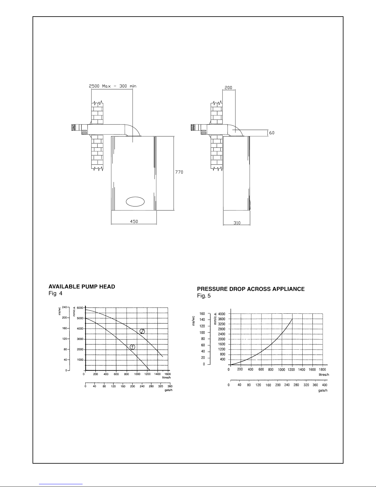
Fig. 3
OVERALL DIMENSION

NOMINAL HEAT INPUT NET QMS 24.8 kW
MINIMUM HEAT INPUT NET 13.0 kW
NOMINAL HEAT OUTPUT 23.8 kW
NOMINAL HEAT OUTPUT CONDENSING 26.2 kW
MINIMUM HEAT OUTPUT 10.6 kW
MINIMUM HEAT OUTPUT CONDENSING 13.7 kW
GAS RATE max 2.5 m
3
/h
AFTER 10 MINUTES min 1.3 m
3
/h
INLET PRESSURE 20 mbar
BURNER PRESSURE C.H. max 10.5 mbar
min 2.0 mbar
MAIN BURNER INJECTORS Nr. 13 x 1.25
ELECTRICAL SUPPLY 230 V ~ 50 HZ
POWER CONSUMPTION 150 W
EXTERNAL FUSE RATING 3A
INTERNAL FUSE 3.15 A (20 mm to BS 4265)
DRY WEIGHT 46 kg
WATER CONTENT C.H. 2.1 litre
GAS SUPPLY CONNECTION 15 mm compression isolating valve
FLOW CONNECTION C.H. 22 mm compression isolating valve
RETURN CONNECTION C.H. 22 mm compression isolating valve
SAFETY DISCHARGE C.H. 15 mm copper pipe
CONDENSATION DRAIN 3/4” (21.5 mm) push fi t over fl ow
MAX COLD WATER CAPACITY WITHOUT ADDITIONAL EXPANSION VESSEL 110 LITRE
SEALED WATER SYSTEM C.H.
MAX PRESSURE PHS 2.5 bar
MINIMUM WORKING PRESSURE 0.5 bar
7 LITRES EXPANSION VESSEL PRE-CHARGE-PRESSURE 0.5 bar
CENTRAL HEATING OPERATING TEMPERATURE MAX 85°C MIN 45°C
DESIGN FLOW RATE 1102 I/h 20 °C RISE
MINIMUM FLOW RATE C.H. 503 I/min
FLUE OUTLET NOM. DIAMETER 100 mm specially supplied with boilers
DESTINATION: AT, DK, Fl, SE, CATEGORY I
2H
DESTINATION: GB, IE, CH, ES, IT, PT CATEGORY II2H3+
FLUE TYPE - C12 - C32 - C52 NOX 4
SECTION 3 TECHNICAL DATA
CSI SYSTEM AAA (T) 780 Series
TABLE 1
NATURAL GAS (G 20) І2H - П2H3+
8
SECTION 3 TECHNICAL DATA
CSI SYSTEM AAA (T) 780 Series
TABLE 1/A
LPG (G 30 - G 31) І3+ - П2H3+
NOMINAL HEAT INPUT NET QMS 24.8 kW
MINIMUM HEAT INPUT NET 13.0 kW
9
NOMINAL HEAT OUTPUT 23.8 kW
NOMINAL HEAT OUTPUT CONDENSING 26.2 kW
MINIMUM HEAT OUTPUT 10.6 kW
MINIMUM HEAT OUTPUT CONDENSING 13.7 kW
GAS RATE max G31 0.9 m
3
/h G30 0.7 m3/h
AFTER 10 MINUTES min 0.5 m
3
/h 0.4 m3/h
INLET PRESSURE G31 37mbar G30 28-30 mbar
BURNER PRESSURE C.H. max G31 35.4mbar G30 27.3 mbar
min 7.3 mbar 7.0 mbar
MAIN BURNER INJECTORS Nr 13 x 0.75
ELECTRICAL SUPPLY 230 V ~ 50 HZ
POWER CONSUMPTION 150 W
EXTERNAL FUSE RATING 3A
INTERNAL FUSE 3.15 A (20 mm to BS 4265)
DRY WEIGHT 46 kg
WATER CONTENT C.H. 2.1 litre
WATER CONTENT 0.5 litre
GAS SUPPLY CONNECTION 15 mm compression isolating valve
FLOW CONNECTION C.H. 22 mm compression isolating valve
RETURN CONNECTION C.H. 22 mm compression isolating valve
SAFETY DISCHARGE C.H. 15 mm copper pipe
CONDENSATION DRAIN 3/4” (21.5 mm) push fi t over fl ow
MAX COLD WATER CAPACITY WITHOUT ADDITIONAL EXPANSION VESSEL 110 LITRE
SEALED WATER SYSTEM C.H.
MAX PRESSURE PHS 2.5 bar
MINIMUM WORKING PRESSURE 0.5 bar
7 LITRES EXPANSION VESSEL PRE-CHARGE-PRESSURE 0.5 bar
CENTRAL HEATING OPERATING TEMPERATURE MAX 85°C MIN 35°C
DESIGN FLOW RATE 1102 I/h 20 °C RISE
MINIMUM FLOW RATE C.H. 503 I/min
FLUE OUTLET NOM. DIAMETER 100 mm specially supplied with boilers
DESTINATION: BE, FR CATEGORY I
2H+
DESTINATION: GB, IE, CH, ES, IT, PT CATEGORY II2H3+
FLUE TYPE - C12 - C32 - C52 NOX 4

10
The manufacturer’s notes must NOT be
taken, in any way, as overriding statutory
obligations.
IMPORTANT:
These appliances are CE certificated for safety
and performance. It is, therefore, important that
no external control devices e.g. flue dampers,
economisers etc. are directly connected to this
appliance unless covered by these Installation
and Service Instructions or as otherwise
recommended by Ravenheat in writing. If in
doubt please enquire.
Any direct connection of a control device
not approved by Ravenheat could invalidate
the certification and the normal appliance
warranty.
It could also infringe the Gas Safety regulations
and the above regulations.
NOTE:
The Ravenheat CSI SYSTEM AAA (T) 780
series combination boiler has been tested and
examined by ADVANTICA, and is certified to
comply with PrEN 483 and BS EN 625.
4.2 LOCATION OF BOILER
4.2.1 Siting of the Ravenheat CSI SYSTEM AAA (T)
780 series Combi Boiler must be as follows.
The position of installation should be within
the building, unless otherwise protected by a
suitable enclosure.
Adequate space for installation, servicing and
air circulation around boiler must be allowed
for.
The Ravenheat CSI SYSTEM AAA (T) 780
Series Combi Boiler must be fitted on a flat and
vertical wall capable of adequately supporting
the weight of the boiler and any ancillary
equipment.
The appliance may be installed on a combustible
wall subject to the requirements of the Local
Authority and Building Regulations.
LPG versions of this appliance shall not be
installed in cellars or basements.
4.3 CLEARANCES AROUND THE APPLIANCE
4.3.1 The following minimum free spaces, required
for installation inspection and servicing, must
be left around the boiler
18 inches (450 mm) in front
5 inches (125 mm) above
6 inches (150 mm) below
0.2 inches (5 mm) on each side
1 inch (25 mm) in front when installed in a
cupboard.
SECTION 4 GENERAL REQUIREMENTS
4.1 SAFETY
Gas Safety (Installation and Use).
Regulations.
It is law that all gas appliances are installed
and serviced by a registered installer in
accordance with the above regulations and
these installation instructions. All registered
installers carry a I.D. card and have a
registration number. Both should be recorded
in your boiler log book. You can check your
installer in the gas safe register. Failure to
install appliances correctly could lead to
prosecution. It is in your own interest, and that
of safety, to ensure the law is complied with.
The installation of the boiler MUST be in
accordance with the latest I.E.E. (BS 7671)
Wiring Regulations, local building regulations,
bye-laws of the local water authority, the
building regulations and the Building Standards
(Scotland) and any relevant requirements of
the local authority.
4.1.1 GENERAL INFORMATION
Both the user and the manufacturer rely
heavily on the installer, whose job it is to
install the combination boiler and connect
it to a correctly designed heating system.
Acquaint yourself with the British Standards
concerning installation requirements. If you
need advice on any points your Ravenheat
Technical Services Office would be pleased to
help. It is recommended that tools suitable for
brass fittings are used, and have a capability
to accomodate hexagon sizes up to 50 mm.
CODES OF PRACTICE/Ref: Documents
Detailed recommendations are contained in the
following British Standard Codes of Practice:
BS.6891 Low pressure installation pipes.
BS.6798 Installation of gas fired hot water
boilers of rated input not exceeding
60 kW.
BS.5449 Forced circulation hot water systems.
BS.5546 Installation of gas hot water supplies
domestic purposes (2nd Family
Gases).
BS.5440: 1 Flues (for gas appliances of rated
input not exceeding 60 kW).
BS.5440: 2 Ventilation (for gas appliances of
rated input not exceeding 60 kW).
DD 189: 1990 Discharge of condensate.
Health & Safety Document No.635
The Electricity at Work Regulations, 1989.
11
4.4 IMPORTANT NOTICE
4.4.1 If the combination boiler is to be fitted in a
timber framed building it should be fitted in
accordance with the British Gas Publication
Guide for Gas Installations in Timber Frame
Housing Reference DM2, if in doubt advice
must be sought from the local gas supplier. The
combination boiler may be installed in any room
or internal space, although particular attention
is drawn to the requirements of the current
I.E.E. Wiring Regulations, and in Scotland the
electrical provisions of the Building Regulations
applicable in Scotland. With respect to the
installation of the combnation boiler in a room
or internal space containing a bath or shower.
Where a room sealed appliance is installed
in a room containing a bath or shower, any
electrical switch or appliance control, utilising
mains electricity should be so situated that it
cannot be touched by a person using a bath or
shower.
A compartment used to enclose the combination
boiler MUST be designed and constructed
specifically for this purpose. An existing
cupboard, or compartment, may be used
provided it is modified accordingly Samples of
the CSI 85 (T) 780 series combination boiler
have been examined by B.G. Technology
Notified Body, and is certified to comply with the
essential requirements of the Gas Appliance,
Directive 90/396/EEC, the Low Voltage,
Directive 72/23/EEC and shows compliance
with the Electro Magnetic Compatibility,
Directive 89/336/EEC and are therefore
permitted to carry the CE Mark.
The appliance has been tested and approved
by the WRc as meeting the requirements of
G3 and L of the Building regulations and water
Bylaws Scheme - Approved Products.
4.5 GAS SUPPLY
4.5.1 A gas meter is connected to the service pipe
by the Local Gas Region or the Local Gas
Region contractor. An existing meter should
be checked preferably by the Gas Region to
ensure that the meter is adequate to deal with
the rate of gas supply required for all appliances
it serves. Installation pipes should be fitted in
accordance with BS 6891. Pipework from the
meter to the boiler must be of adequate size
(22 mm) min To within at least 3 metre of
the boiler (15 mm) min can then be used for
remaining pipe work to the appliance. A smaller
size than the boiler inlet gas connection should
not be used. The complete installation must be
tested for soundness as described in the above
Code.
N.B. if the gas supply for the boiler serves
other appliances ensure an adequate
supply is available both to the boiler and the
other appliances when they are in use at the
same time.
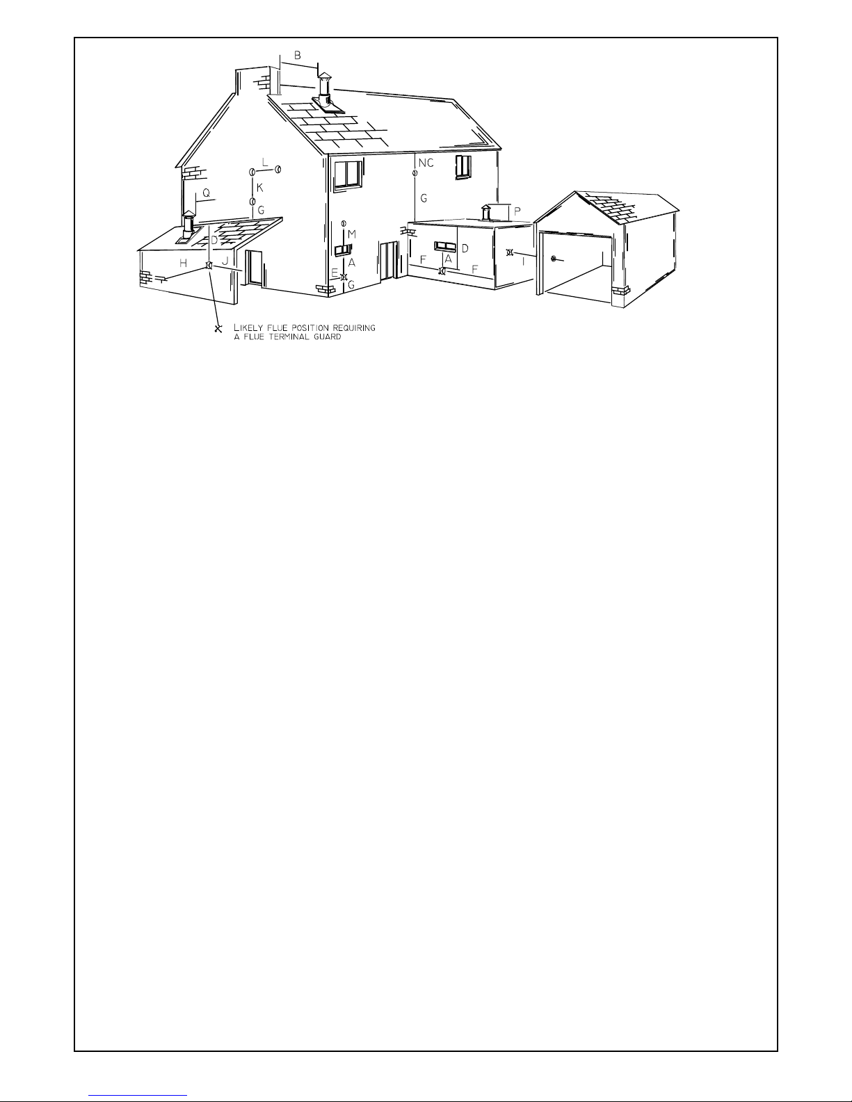
4.6 FLUE SYSTEM
4.6.1 The terminal should be located where dispersal
of combustion products is not impeded and with
due regard for the damage or discolouration
that might occur to building products in the
vicinity (see fig. 5).
The terminal must not be located in a place
where it is likely to cause a nuisance. In cold
and/or humid weather water vapour may
condense on leaving the flue terminal, the
effect of such steaming must be considered
The terminal must not be closer than 25 mm
(1 in) to any combustible material For protection
of combustibles, refer to BS 5440.1.
Where a flue terminal is installed less than
1000 mm. from a plastic, or painted gutter;
or 500 mm from painted eaves, an aluminium
shield 1000 mm long, should be fitted to the
underside of the gutter or painted surface.
Pluming will occur at the terminal so, where
possible, terminal positions which could cause
a nuisance should be avoided.
The flue must be installed in accordance with
the recommendations of BS 5440: Part 1.
IMPORTANT NOTES
For greater fl ue lengths see twin fl ue
instructions.
Flue must be positioned in a place not
likely to cause a nuisance.
IMPORTANT: The following notes are intended for
general guidance.
The boiler MUST be installed so that the terminal
is exposed to external air.
It is important that the position of the terminal
allows the free passage of air across it at all
tirnes.
Minimum acceptable spacing from the terminal to
obstructions and ventilation opening are specifi ed
in Fig. 5.
Note positions: Due to the terminal design,
installation is possible with clearances less than
those specifi ed in BS 5440, Part 1.
12
Fig. 6
NOTE: The flue must be terminated in a place not
likely to cause a nuisance.
4.6.2 A concentric vertical flue kit is available for
flueing applications up to a maximum height of
4 metres.
For further details see vertical flue installation
instructions.
4.7 AIR SUPPLY
4.7.1 The following notes are intended for general
guidance.
The room sealed fan flued boiler does not
require a permanent air vent for combustion
air supply.
When installed in a cupboard or compartment
ventilation is not required.
4.8 WATER CIRCULATION (central heating)
4.8.1 Detailed recommendations are given in
BS 6798:1987/5449:1990 (for smallbore
and microbore central heating systems).
The following notes are given for general
guidance.
4.8.2 Pipework
Copper tubing to BS 2871 1.1.1971 is
recommended for water pipes. Jointing should
be either with capillary soldered or with
compression fittings.
Where possible pipes should have a gradient
to ensure air is carried naturally to air release
points and water flows naturally to drain taps.
It should be ensured as far as possible that
the appliance heat exchanger is not a natural
collecting point for air except where providing
useful heat, pipes should be insulated to
prevent heat loss and to avoid freezing.
Particular attention should be paid to pipes
passing through ventilated spaces in roofs and
under floors.
4.8.3 An automatic system by-pass is included
within the boiler. The boiler is suitable for use
in system with thermostatic radiator valves
and additional by-pass is required.
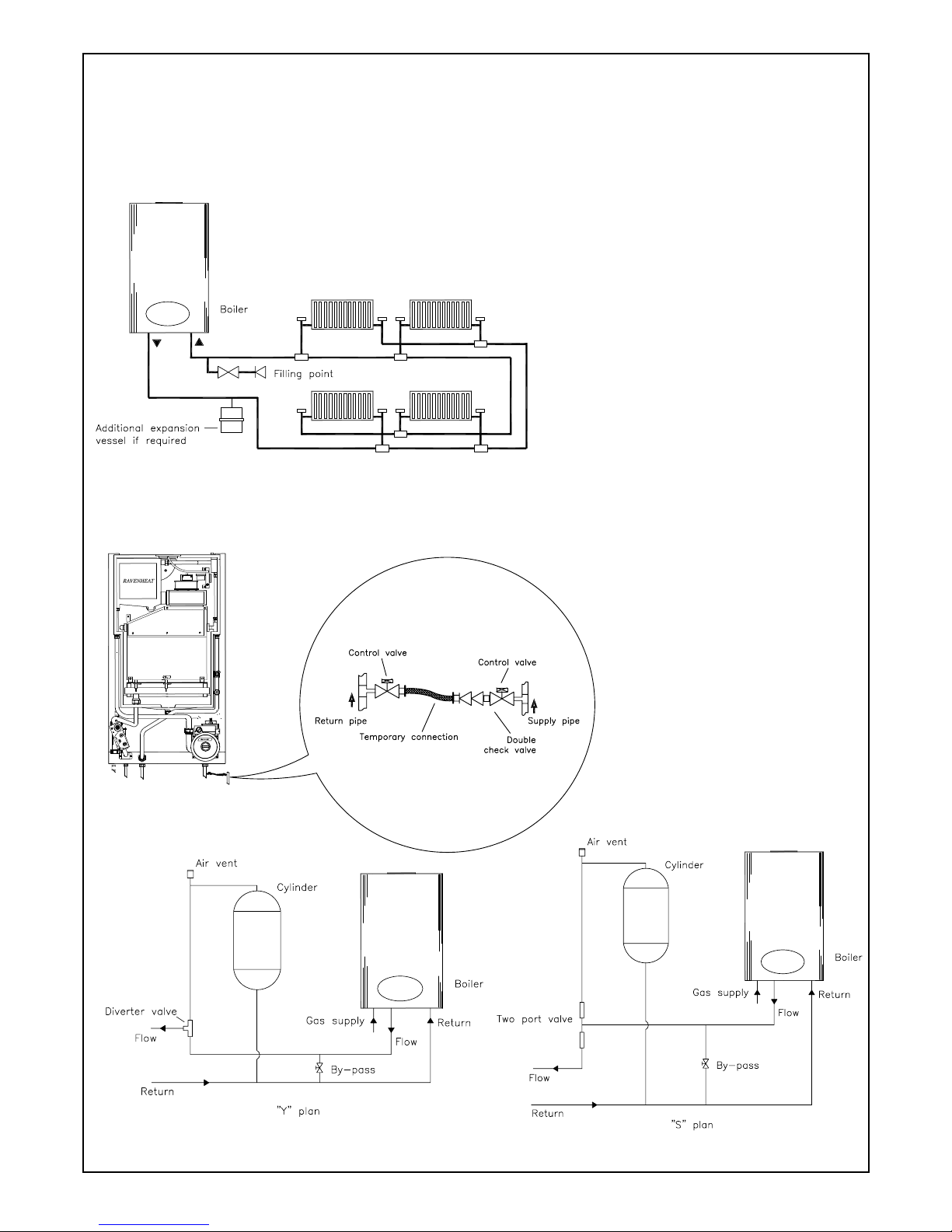
4.8.4 System design
Fig. 7 illustrates typical heating only layout.
Figs. 9 and 10 iluustrates typical layout with
“Y” or “S” plan system.
Terminal position for fan assisted boiler (minimum distance) mm
A - Directly below an open window or other opening (e.g. air brick) 300
B - From a vertical structure on the roof 150
C - Below eaves 200
D - Below balconies or car port roof 200
E - From a vertical drain pipes and soil pipes 150
F - From an internal or external corner 100
G - Above ground or below balcony level 300
H - From a surface facing a terminal 600
I - From a terminal facing the terminal 1200
J - From an opening in the car port (e.g. door window) into dwelling 1200
K - Vertically from a terminal on the same wall 1500
L - Horizontally from a terminal on the same wall 300
M - Above an opening, air brick, opening
windows etc... 300
N - Below gutters, soil pipes or drain pipes 75
P - Above intersection with roof 300
13
4.8.5 Draining tap
These must be located in accessible positions
to permit the draining of the whole system.
The taps must be at least 15 mm nominal size
and manufactured in accordance with BS 2870
1980.
4.8.6 Air release points
These must be fitted at all high points where
air will naturally collect, and must be sited to
facilitate complete filling of the system.
4.8.7 The appliance has an integral sealed expansion
vessel to accommodate the increase of water
volume when the system is heated.
It can accept up to 6 Its of expansion water.
If the appliance is connected to a system with
an unusually high water content, calculate
the total expansion and add additional sealed
expansion capacity as appropriate (Fig. 7).
In general, modern systems will present no
problem.
4.8.8 Mains water feed: central heating
There must be no direct connection to the
mains water supply, even through a non return
valve, without the approval of the Local Water
Authority.
Fig. 9
Fig. 7
Fig. 10
Fig. 8
PERMISSIBLE METHOD OF FILLING
Fig. 8 depicts the requirements of diagram
R24.2a of Water Supply (Water Fittings)
regulations 1999.
14
B) Where fitting of a make up vessel would
be difficult, RE-PRESSURING of the system
can be done. See section on FILLING. If the
capacity of the central heating system should
exceed 110 Litres, an additional vessel should
be installed on the return to the combination
boiler from the heating system (Fig. 7).
Guidance on vessel sizing is given in (Table
3).
Reference should be made to British Gas
Publications, «Material and Installation
Specifications for Domestic Central Heating
and Hot Water». Draining taps should be
at least 1/2” in BSP nominal size and be in
accordance with BS 2879.
4.8.8 Installation to an existing central heating
system.
The combination boiler is designed to operate
on a sealed system only. Therefore if the
existing system is of the open water type it will
have to be modified to comply with BS 5376
Part 2.
Before installing a new combination boiler to
an existing system, flush out the old system
with a recommended descaling agent.
It is important that the correct concentration
of the water treatment product is maintained
in accordance with the manufacturers’
instructions.
If the boiler is installed in an existing system
any unsuitable additives MUST be removed by
thorough cleansing.
BS 7593:1992 details the steps necessary
to clean domestic central heating system.
Also check pipework and renew any corroded
pipework or fittings. Valve glands must be
repacked or replaced wherever necessary and
any defective controls exchanged.
4.8.9 WATER TREATMENT
This boiler has a secondary ALUMINIUM alloy
heat exchanger Ravenheat recommended only
the use of FERNOX- COPAL or SENTINEL
X100 water treatment products, which must
be used in accordance with the manufacturers
instructions. For further information contact:
Fernox Manufacturing Co. Ltd.
Tel 01799 550811
Sentinel Division Betz Dearborn Ltd.
Tel. (0151) 424 5351
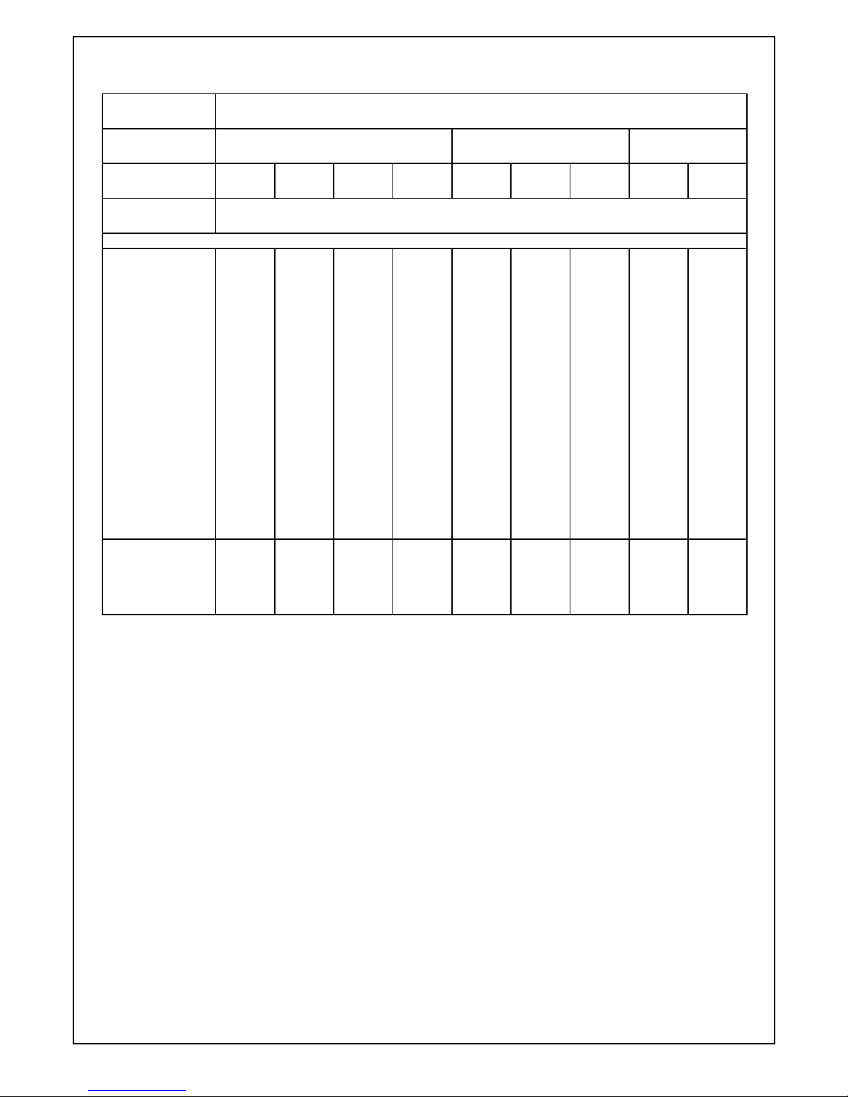
Safety
valve setting (bar)
3.0
Vessel charge
pressure (bar)
0.5 1.0 1.5
Initial system
pressure (bar)
0.5 1.0 1.5 2.0 1.0 1.5 2.0 1.5 2.0
T otal water
content of system
EXPANSION VESSEL VOLUME (LITRES)
Litres
25
50
75
100
125
150
175
200
225
250
275
300
325
350
375
400
425
450
475
500
2.1
4.2
6.3
8.3
10.4
12.5
14.6
16.7
18.7
20.8
22.9
25.0
27.0
29.1
31 .2
33.3
35.4
37.5
39.6
41.6
3.5
7.0
10.5
14.0
17.5
21.0
24.5
28.0
31 .5
35.0
38.5
42.0
45.5
49.0
52.5
56.0
59.5
63.0
66.5
70.0
6.5
12.9
19.4
25.9
32.4
38.8
45.3
51 .8
58.3
64.7
71 .2
77.7
84.1
90.6
97 .1
103.6
110.1
116.5
123.0
125.9
13.7
27.5
41.3
55.1
68.9
82.6
96.4
110.2
124.0
137.7
151 .5
165.3
179 .1
192.8
206.6
220.4
239.2
247.9
261 .7
275.5
2.7
5.4
8.2
10.9
13.6
16.3
19.1
21.8
24.5
27.2
30.0
32.7
35.7
38 .1
40.9
43.6
46.3
49.0
51 .8
54.5
4.7
9.5
14.2
19.0
23.7
28.5
33.2
38.0
42.7
47.5
52..2
57.0
61 .7
66.5
71 .2
76.0
80.7
85.5
90.2
95.0
10.3
20.6
30.9
41.2
51.5
61.8
72.1
82.4
92.7
103.0
113.3
123.6
133.9
144.2
154.5
164.8
175.1
185.4
195.7
206.0
3.9
7.8
11.7
15.6
19.5
23.4
27 .3
31.2
35 .1
39.0
42.9
46.8
50.7
54.6
58.5
62.4
66.3
70.2
74.1
78.0
8.3
16.5
24.8
33.1
41.3
49.6
57.9
66.2
74.5
82.7
91.0
99.3
107.6
115.8
124.1
132.4
140.7
148.9
157.2
165.5
For system volumes
other than those given
above, multiply the
system volume by
the factor across
0.0833 0.140 0.259 0.551 0 .109 0.190 0.412 0.156 0.331
SIZING OF ADDITIONAL EXPANSION VESSEL: TABLE 3
Deduct from the value given in the table the 7 litre vessel supplied.
Note: This pressure can be increased up to 1.5 bar to suit high static head situations, see item 10, other appliance components in the
SERVICING INSTRUCTIONS.
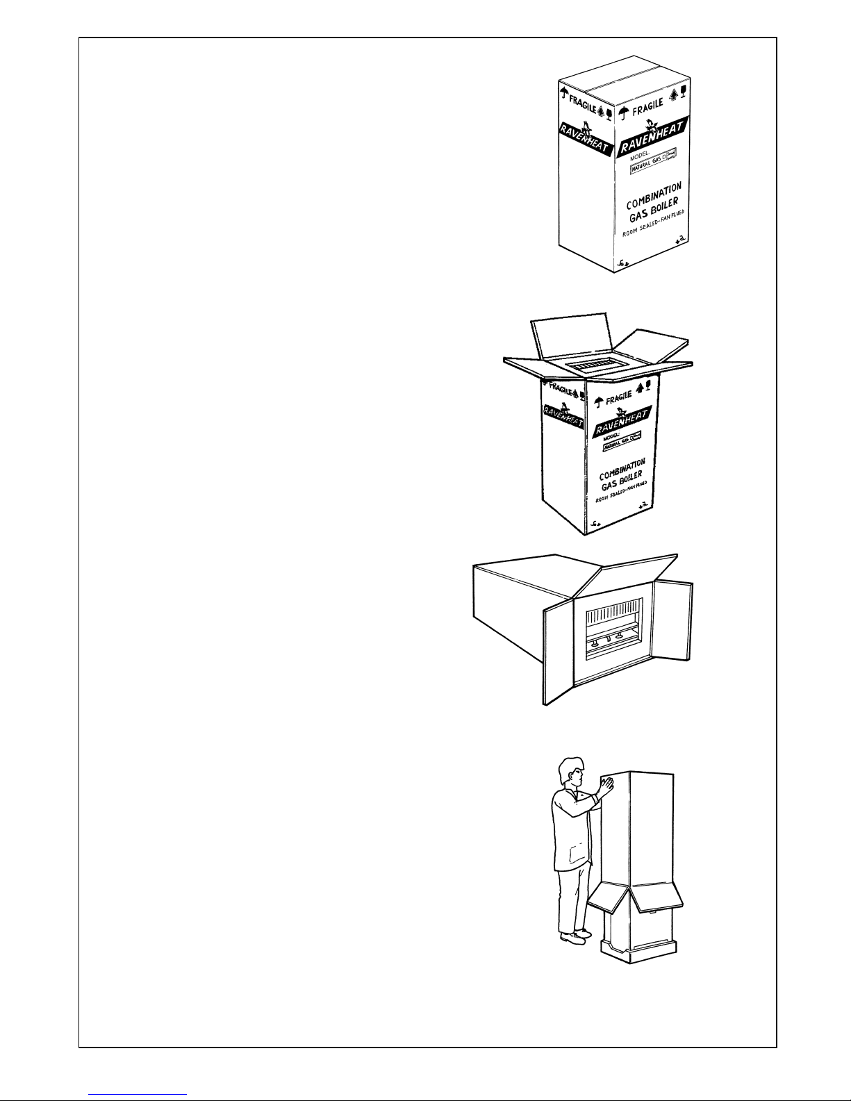
Fig. 11
15
SALAMANDER CURROSION GUARD
Salamander (Eng) Ltd
Tel: (0121) 3780952 /4508
4.8.10 Hard water areas.
If the area of installation is recognized as hard
water, it is recommended that a suitable water
treatment device is installed in the mains.
The water hardness can be determined by using
the standard test paper or by referring to local
water authority.
4.9 DOMESTIC WATER
4.9.1 The domestic hot water must be in accordance
with the relevant recommendations of BS 5546.
Copper tubing to BS 2871 1 is recommended
for water carrying pipework and MUST be used
for pipework carrying potable water.
4.10 ELECTRICAL SUPPLY
Warning: this appliance must be earthed
4.10.1 External wiring to the appliance must be carried
out by a qualified person and be in accordance
with the current I.E.E. Regulations and local
regulations which apply. The Ravenheat boiler is
supplied for connection to a 230 V ~ 50 Hz single
phase supply. The supply must be fused at 3 A.
NOTE. The method of connection to the
electricity supply MUST facilitate complete
electrical isolation of the appliance, by the
use of a fused, double pole isolator, having a
contact separation of at least 3 mm in all poles.
The point of connection to the electricity supply
must be readily accessible and adjacent to
the appliance except, where the appliance is
installed in a bathroom, this MUST be sited
outside the bathroom.
SECTION 5 INSTALLATION
5.1 WARNING
5.1.1 It is MOST IMPORTANT that this appliance is
installed in a VERTICAL POSITION, with the
flue air duct passing through the wall.
Make sure flue slopes 2.5° down towards the
boiler that is 45 mm/m fall per metre of flue
length (Fig. 24).
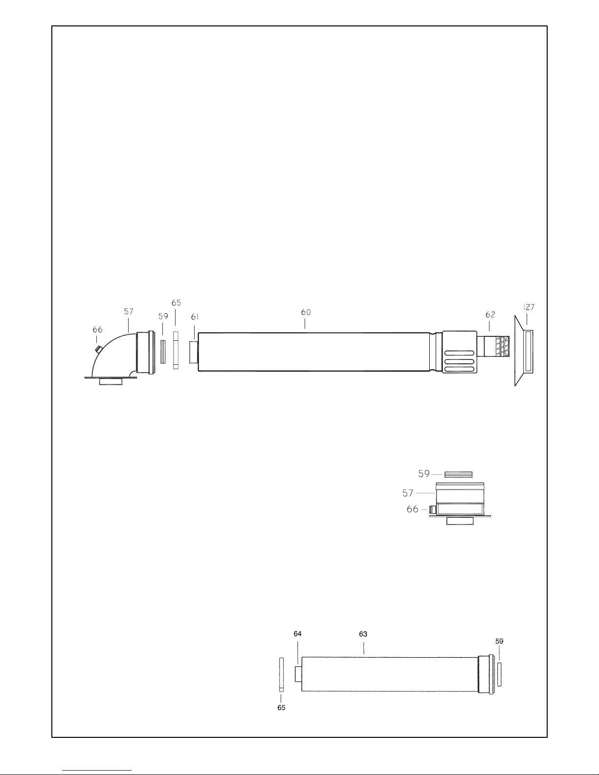
Fig. 12
Fig. 12
Fig. 14
16
5.2 DELIVERY
5.2.1 The appliance carton containing (fi g 11):
a) boiler fully assembled
b) installation instructions and
user instructions
c) white paper template.
Polythene bag containing
a) 2-22 mm compression ball valve complete
with 3/4” washers.
b) 1-15 mm compression ball valve complete
with 1/2” washers.
c) 1-15 mm compression ball valve.
d) 2 coach bolts and wall plugs.
e) screws and dowels
OPTIONAL EXTRAS:
Small carton containing (fi g. 13):
57 - Straight header supplied as an extra cost only when
requested
59 - Rubber seal Ø 60
66 - Flue gas sample point
FLUE EXTENSION BOX CONTAINING (fi g. 14):
1000 mm fl ue extension duct as an extra cost only when
requested for side and vertical fl ue applications
59 - Rubber seal Ø 60
63 - Air intake duct extension
64 - Flue exhaust duct extension
65 - Pipe centering spring
WARNING
Maximum allowable fl ue length 2.5 m
horizontal maximum No 2x1000 mm.
Flue duct extension used with standard fl ue.
Horizontal CSI fl ue kit
(sold separate) Fig. 12.
57 - Flue bend assembly
59 - Rubber seal Ø 60
60 - Air intake duct
61 - Flue exhaust duct
62 - Terminal
65 - Pipe centering spring
66 - Flue gas sample point
127 - Terminal Rubber.
 Loading...