

Technical and illustrative data are not binding and can be modifi ed without prior notice.
The descriptions and illustrations in the present booklet are for guidance purposes only.
RAVENHEAT MANUFACTURING LTD
CHARTISTS WAY, MORLEY, LEEDS, U.K. LS27 9ET
TEL.: 0113 252 7007 - FAX: 0113 238 0229
Website: www.ravenheat.co.uk - E-mail: sales@ravenheat.co.uk
Instructions for Use
Installation and Servicing
To be left with the user
CS 80 (T)
Natural Gas (G20) II
2H3P
G. C. No. 4758146
LPG (G31) II
2H3P
G.C. No. 4758147
CS 90 (T)
Natural Gas (G20) II
2H3P
G. C. No. 4758148
LPG (G31) II
2H3P
G.C. No. 4758149
1312
HIGH EFFICIENCY
CONDENSING
COMBINATION BOILER

6
It is the law that all gas appliances are installed by
a competent person, in accordance with the gas
safety installation and to the current Gas Safety
(Installation and Use) Regulations B.S.5440:2-(2000).
All registered installers carry a Gas Safe Register ID card
and have a registration number. Both should be recorded in
your boiler Log book. You can check your installer’s
registration at www.gassaferegister.co.uk.
ESCAPE OF GAS
Should a gas leak be suspected, contact your gas
supplier without delay.
GAS EMERGENCY NUMBER: 0800111999
Do NOT search for gas leaks with a naked fl ame.
WARNING: This appliance must be earthed.
1.1 INTRODUCTION
Please carefully read the information given in this
booklet to help you gain maximum control from your
appliance with minimum trouble and cost.
Your Ravenheat Condensing Low Nox combination boiler
has been designed to supply your Central Heating and
Domestic Hot Water directly from one unit.
When Central Heating is operating, the circulation will be
interrupted when Domestic Hot Water is being drawn off
(domestic hot water has priority).
This will normally not affect the level of Heating.
PLEASE NOTE:
Due to the high effi ciency of this appliance and resulting
low fl ue gas exhaust temperature a white plume of
condensation vapour (cool steam) will be emitted from the
fl ue outlet terminal, this is quite normal. It will be
particularly evident during periods of low outdoor
temperature or when the boiler is working at its optimum
performance (Plume Management kits are available on
request).
IMPORTANT:
In the unlikely event of the exhaust fl ue gases exceeding
the overheat temperature setting, the boiler operation will
be stopped to prevent damage to the appliance.
1.2 CLEARANCES AROUND THE APPLIANCE
Side clearance:
The position of the appliance must provide a
minimum clearance of only 5 mm as the side panels
do not require removing for servicing.
However, if the option is preferred to remove the
panels then a minimum clearance of 55 mm is
required.
Top clearance:
The top clearance should be a minimum of
125 mm.
Bottom clearance:
A minimum bottom clearance of 80 mm is
A minimum bottom clearance of 80 mm is
required between the appliance
required between the appliance and any surface,
though 150 mm is preferred whenever
possible.
Front clearance:
A minimum of 450 mm is required in front of
the appliance for access during servicing, the
front clearance can be reduced when installed
in a cupboard to 25 mm from the access door.
USER CONTROLS
USER CONTROLS
This appliance is designed to operate with the minimum
This appliance is designed to operate with the minimum
of ease for the user. All the controls are found on the
of ease for the user. All the controls are found on the
control panel on the front of the boiler.
control panel on the front of the boiler.
1.3 OPERATING SAFETY CHECKS TO PROTECT
1.3 OPERATING SAFETY CHECKS TO PROTECT
YOUR APPLIANCE (CHECKING THE SYSTEM
YOUR APPLIANCE (CHECKING THE SYSTEM
PRESSURE)
PRESSURE)
Before lighting the appliance check that the Central
Before lighting the appliance check that the Central
Heating system pressure is not less than 1 bar. If it
Heating system pressure is not less than 1 bar. If it
is below this it will be ecessary to re-pressurise the
is below this it will be ecessary to re-pressurise the
system, between 1 and 1.5 bar to allow the boiler to
system, between 1 and 1.5 bar to allow the boiler to
operate. To view the system pressure press the P button
operate. To view the system pressure press the P button
once, this will display the current pressure
once, this will display the current pressure
(if the
(if the
pressure is on nil or too low, then error code 08E is
pressure is on nil or too low, then error code 08E is
displayed).
displayed).
A fi lling device (fi lling loop) will have been fi tted on the
A fi lling device (fi lling loop) will have been fi tted on the
system.
system.
This is usually on the pipework near to the boiler. If you
This is usually on the pipework near to the boiler. If you
are unsure of its position, or you cannot identify it, consult
are unsure of its position, or you cannot identify it, consult
the installer who fi tted the boiler.
the installer who fi tted the boiler.
The fi lling loop usually consists of two taps and a
The fi lling loop usually consists of two taps and a
separate silver coloured braided fl exible pipe with
separate silver coloured braided fl exible pipe with
connection fi ttings. Only when re-pressurising should the
connection fi ttings. Only when re-pressurising should the
braided fl exible pipe be connected between the two taps,
braided fl exible pipe be connected between the two taps,
ensure that the nuts or the pipe ends are tightened
ensure that the nuts or the pipe ends are tightened
onto the taps.
onto the taps.
Fully open one of the taps fi rst and then while monitoring
Fully open one of the taps fi rst and then while monitoring
the water pressure on the digital display, carefully open
the water pressure on the digital display, carefully open
the second tap. When the water pressure is to a
the second tap. When the water pressure is to a
maximum of 1.5 bar turn both taps off.
maximum of 1.5 bar turn both taps off.
Disconnect the fl exible pipe from the taps (a small
Disconnect the fl exible pipe from the taps (a small
amount of water may be present).
amount of water may be present).
Keep the pipe in a safe place for future use.
Keep the pipe in a safe place for future use.
Press the P button once to return to the main screen.
Press the P button once to return to the main screen.
In the event of an error, the appliance will show a
In the event of an error, the appliance will show a
sequence code displayed on the digital display of the
sequence code displayed on the digital display of the
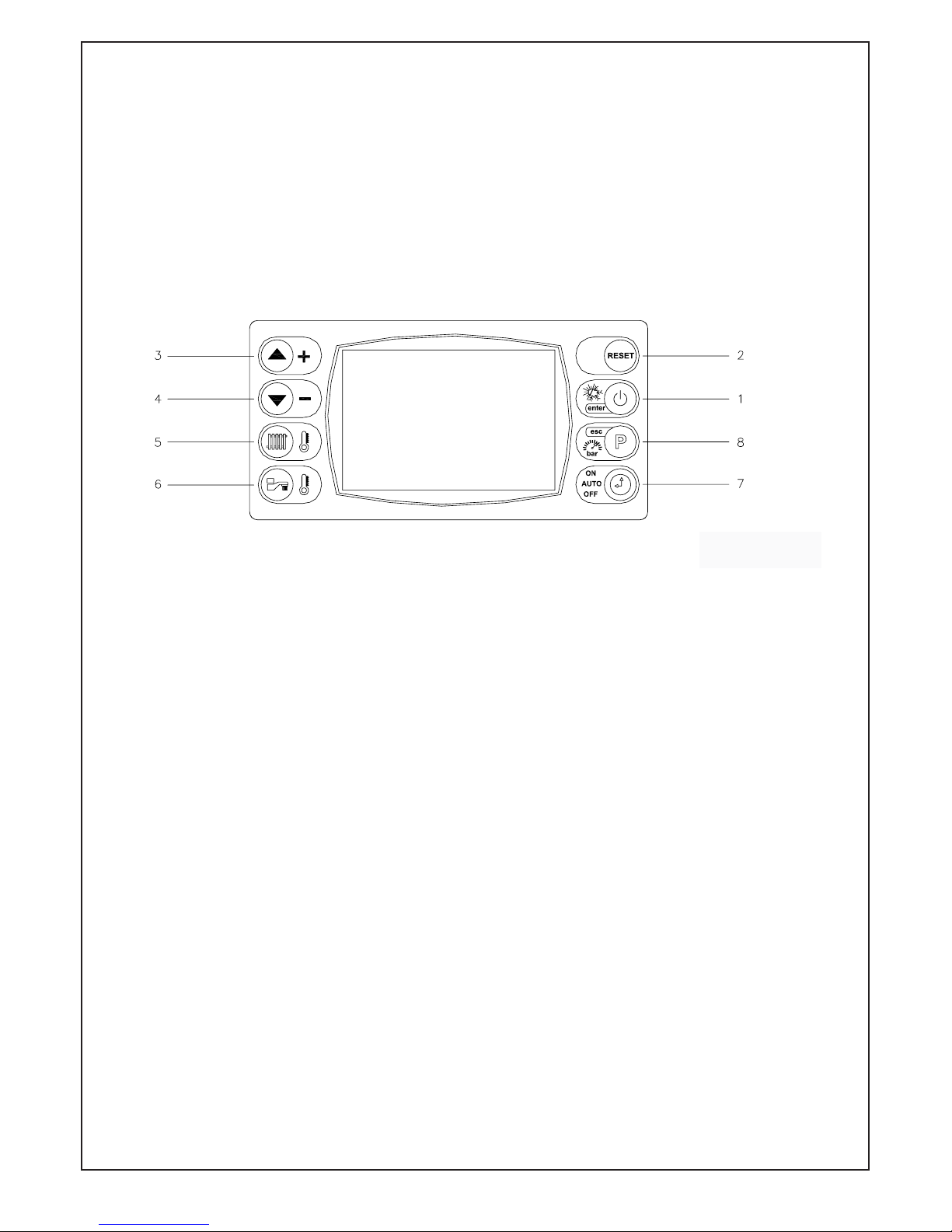
control panel (fi g. 1). By pressing the “RESET“
control panel (fi g. 1). By pressing the “RESET“
button it is possible to relight the boiler (see page 51
button it is possible to relight the boiler (see page 51
for list of error codes).
for list of error codes).
1 USERS GUIDE
7
1.4 APPLIANCE STATUS INDICATORS
Your boiler is equipped with a large LCD display
that indicates the appliance operating status
(fi g. 1).
After a long period switched off (no power
supply), the fi rst switch on the internal backup
circuit will charge in order to
maintain time
maintain time
and update parameters. The screen will display
and update parameters. The screen will display
CLOW, after a few minutes of power su
CLOW, after a few minutes of power supply the
display will be charged enough to allow all the
functions.
Fig. 1
During the initial charge time, the display doesn’t
allow the visualisation and/or modifi cation function
parameters. Instead other functions are working.
When the appliance operates in rest mode, the
display shows the boiler temperature and, for the
time clock version only, the time. Alternatively the
digital display also shows the water pressure.
KEY:
1 - ON/OFF button.
Press to turn the boiler ON, “SUM” (hot water
only) “WIN” (hot water and heating if set) and
OFF.
Press the button also to confi rm selections.
2 - Press to reset the appliance if ever an error
code is displayed.
3/4 - Temperature and function mode selectors.
Press the arrow up or the arrow down to
increase or decrease the heating or domestic
hot water outlet temperature, when the digital
display is in hot water or domestic set-point
temperature.
Press also to show the boiler values or to
show the options program when the digital
display is in menu setting.
5 - Press to set the Central Heating
Temperature required
(when in winter mode).
Press the arrow up or the arrow down buttons
to increase or decrease the temperature.
6 - Press to set the Domestic Hot Water
Temperature required.
Press the arrow up or the arrow down buttons
to increase or decrease the temperature.
7 - TIMER MODE (time clock version only).
Press to select “Auto” (heating times set), “Manual”
(heating on all the time) and off (heating off).
8 - Press to show the boiler values.
Use the arrow up and arrow down buttons to select
the following information:
PBAR: water pressure
SFAN: speed fan (the display shows 3 digits
(e.g. 500 = 5000 rpm)
TFLOW: fl ow temperature
TRET: return temperature
TDHW: domestic hot water temperature
PWR: % power of modulation.
- Press for 3 seconds to enter into menu.
Use the arrow up or arrow down buttons to select
the following options:
- TIME (time clock version only): It is possible to
set the time and the current day (Monday 1,
Tuesday 2, Wednesday 3, Thursday 4, Friday 5,
Saturday 6, Sunday 7), see section 1.7.
- PTMR (only time clock version): It is possible to set
the timer, see section 1.8.
- BOIL: It is possible to set the boiler parameters
C.H. max fan speed
D.H.W. max fan speed
Keep hot: “0” disabled and “1” enabled
C.H. High/Low temperature: “1” high/“2” low.
 Loading...