

Page 1
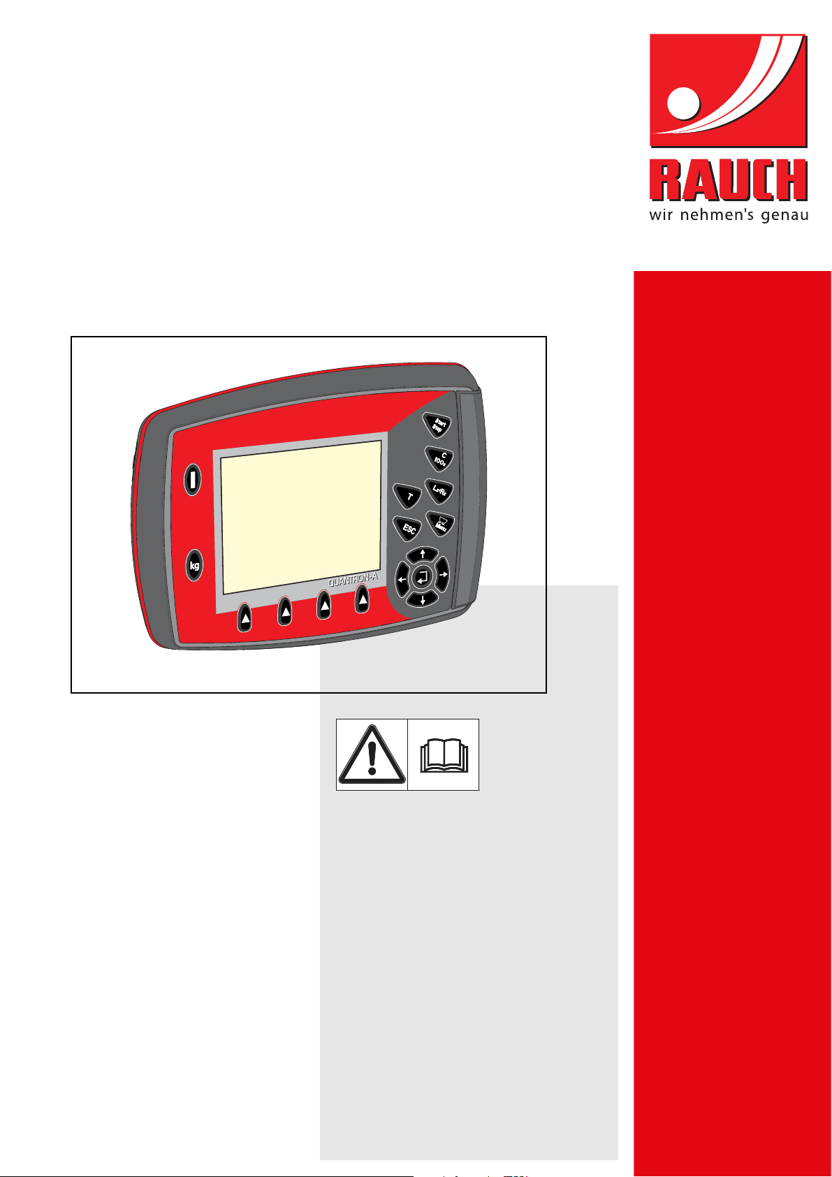
INSTRUCTION MANUAL
UKS
LINUS
Please read carefully
before using the machine.
Keep for future reference.
This instruction manual/assembly instruction is to be considered as part of
the machine. Suppliers of new and second-hand machines are required to
document in writing that the instruction manual/assembly instruction was
delivered with the machine and handed over to the customer.
QUANTRON-A
Original instructions
5901348-c-en-0617
Page 2

Preface
Dear customer,
By purchasing the QUANTRON-A control unit for the universal box spreader UKS and LINUS, you
have shown confidence in our product. Thank you very much! We would like to justify this confidence. You have purchased a reliable, high-performance control unit. Should you, against all expectations, encounter any problems: our customer service is always there for you.
Please read this operator’s manual as well as the operator’s manual of the universal box
spreader carefully before commissioning, and follow the advice given.
This manual may also describe equipment and options that are not included in your control unit.
Please note that damage caused by incorrect operation or improper use may not be covered by
warranty claims.
CAUTION
Note the serial number of the control unit and of the machine.
The control unit QUANTRON-A is factory-calibrated for the fertiliser spreader with which it has
been delivered. It cannot be connected to another fertiliser spreader without requiring additional
calibration.
Please state this information when ordering spare parts or accessories, and in case of complaints.
Serial number of control unit Serial number of the universal box
spreader
Year of manufacture
Technical improvements
We are continuously improving our products. Therefore, we reserve the right to make any
improvements and changes to our machine that we consider necessary without notice.
This constitutes no obligation to make such improvements or changes on machines that
have already been sold.
We will be pleased to answer any other questions that you might have.
Yours sincerely
RAUCH
Landmaschinenfabrik GmbH
Page 3

Table of Contents
Preface
Technical improvements
1 User instructions 1
1.1 About this operator's manual . . . . . . . . . . . . . . . . . . . . . . . . . . . . . . . . . . . . . . . . . . . 1
1.2 Information on the illustration. . . . . . . . . . . . . . . . . . . . . . . . . . . . . . . . . . . . . . . . . . . 1
1.2.1 Significance of warnings . . . . . . . . . . . . . . . . . . . . . . . . . . . . . . . . . . . . . . . . 1
1.2.2 Instructions and procedures. . . . . . . . . . . . . . . . . . . . . . . . . . . . . . . . . . . . . . 2
1.2.3 Listings. . . . . . . . . . . . . . . . . . . . . . . . . . . . . . . . . . . . . . . . . . . . . . . . . . . . . . 3
1.2.4 References. . . . . . . . . . . . . . . . . . . . . . . . . . . . . . . . . . . . . . . . . . . . . . . . . . . 3
1.2.5 Menu hierarchy, keys and navigation. . . . . . . . . . . . . . . . . . . . . . . . . . . . . . . 3
2 Layout and function 5
2.1 Overview of supported universal box spreaders . . . . . . . . . . . . . . . . . . . . . . . . . . . . 5
2.2 Configuration of the control unit. . . . . . . . . . . . . . . . . . . . . . . . . . . . . . . . . . . . . . . . . 5
2.3 Layout of the control unit - overview . . . . . . . . . . . . . . . . . . . . . . . . . . . . . . . . . . . . . 6
2.4 Control elements . . . . . . . . . . . . . . . . . . . . . . . . . . . . . . . . . . . . . . . . . . . . . . . . . . . . 7
2.5 Display . . . . . . . . . . . . . . . . . . . . . . . . . . . . . . . . . . . . . . . . . . . . . . . . . . . . . . . . . . . . 9
2.5.1 Operating screen of the winter spreader UKS . . . . . . . . . . . . . . . . . . . . . . . . 9
2.5.2 Operating screen of the UKS GB and LINUS fertiliser spreaders . . . . . . . . 11
2.6 Structural menu overview . . . . . . . . . . . . . . . . . . . . . . . . . . . . . . . . . . . . . . . . . . . . 13
2.6.1 Winter spreader UKS series. . . . . . . . . . . . . . . . . . . . . . . . . . . . . . . . . . . . . 13
2.6.2 UKS GB and LINUS series fertiliser spreaders . . . . . . . . . . . . . . . . . . . . . . 14
3 Attachment and installation 15
3.1 Requirements for the tractor . . . . . . . . . . . . . . . . . . . . . . . . . . . . . . . . . . . . . . . . . . 15
3.2 Connections, sockets. . . . . . . . . . . . . . . . . . . . . . . . . . . . . . . . . . . . . . . . . . . . . . . . 15
3.2.1 Power supply . . . . . . . . . . . . . . . . . . . . . . . . . . . . . . . . . . . . . . . . . . . . . . . . 15
3.2.2 7-pin plug connector. . . . . . . . . . . . . . . . . . . . . . . . . . . . . . . . . . . . . . . . . . . 16
3.3 Connecting the control unit . . . . . . . . . . . . . . . . . . . . . . . . . . . . . . . . . . . . . . . . . . . 17
I
Page 4

Table of Contents
4 Operation QUANTRON-A 21
4.1 Switching on the control unit . . . . . . . . . . . . . . . . . . . . . . . . . . . . . . . . . . . . . . . . . . 21
4.2 Menu navigation . . . . . . . . . . . . . . . . . . . . . . . . . . . . . . . . . . . . . . . . . . . . . . . . . . . . 23
4.3 Weighing trip counter . . . . . . . . . . . . . . . . . . . . . . . . . . . . . . . . . . . . . . . . . . . . . . . . 24
4.3.1 Trip counter. . . . . . . . . . . . . . . . . . . . . . . . . . . . . . . . . . . . . . . . . . . . . . . . . . 25
4.3.2 Residual material . . . . . . . . . . . . . . . . . . . . . . . . . . . . . . . . . . . . . . . . . . . . . 26
4.4 Main menu . . . . . . . . . . . . . . . . . . . . . . . . . . . . . . . . . . . . . . . . . . . . . . . . . . . . . . . . 28
4.5 Spreading material settings . . . . . . . . . . . . . . . . . . . . . . . . . . . . . . . . . . . . . . . . . . . 29
4.5.1 Spreading material settings for winter spreaders menu UKS . . . . . . . . . . . . 29
4.5.2 Fertiliser settings for fertiliser spreaders menu . . . . . . . . . . . . . . . . . . . . . . 31
4.5.3 Spreading density/application rate . . . . . . . . . . . . . . . . . . . . . . . . . . . . . . . . 32
4.5.4 Flow factor . . . . . . . . . . . . . . . . . . . . . . . . . . . . . . . . . . . . . . . . . . . . . . . . . . 33
4.5.5 RPM . . . . . . . . . . . . . . . . . . . . . . . . . . . . . . . . . . . . . . . . . . . . . . . . . . . . . . . 34
4.5.6 Calibration test . . . . . . . . . . . . . . . . . . . . . . . . . . . . . . . . . . . . . . . . . . . . . . . 34
4.5.7 Spreading density +/- (winter spreader only UKS) . . . . . . . . . . . . . . . . . . . . 36
4.5.8 +/- application rate (for large fertiliser spreaders UKS GB or LINUS). . . . . . 37
4.5.9 Fertiliser chart . . . . . . . . . . . . . . . . . . . . . . . . . . . . . . . . . . . . . . . . . . . . . . . . 38
4.6 Machine configurat. . . . . . . . . . . . . . . . . . . . . . . . . . . . . . . . . . . . . . . . . . . . . . . . . . 40
4.6.1 Forward speed calibration . . . . . . . . . . . . . . . . . . . . . . . . . . . . . . . . . . . . . . 41
4.6.2 AUTO/MAN mode. . . . . . . . . . . . . . . . . . . . . . . . . . . . . . . . . . . . . . . . . . . . . 44
4.6.3 Special spreading (+%; winter spreader UKS only) . . . . . . . . . . . . . . . . . . . 46
4.6.4 Working width . . . . . . . . . . . . . . . . . . . . . . . . . . . . . . . . . . . . . . . . . . . . . . . . 47
4.6.5 Metering openings . . . . . . . . . . . . . . . . . . . . . . . . . . . . . . . . . . . . . . . . . . . . 47
4.6.6 Simulated speed . . . . . . . . . . . . . . . . . . . . . . . . . . . . . . . . . . . . . . . . . . . . . . 48
4.7 Fast emptying. . . . . . . . . . . . . . . . . . . . . . . . . . . . . . . . . . . . . . . . . . . . . . . . . . . . . . 50
4.8 File/field data . . . . . . . . . . . . . . . . . . . . . . . . . . . . . . . . . . . . . . . . . . . . . . . . . . . . . . 51
4.8.1 Selecting a file . . . . . . . . . . . . . . . . . . . . . . . . . . . . . . . . . . . . . . . . . . . . . . . 52
4.8.2 Starting the recording . . . . . . . . . . . . . . . . . . . . . . . . . . . . . . . . . . . . . . . . . . 53
4.8.3 Stopping the recording . . . . . . . . . . . . . . . . . . . . . . . . . . . . . . . . . . . . . . . . . 54
4.8.4 Importing and exporting files. . . . . . . . . . . . . . . . . . . . . . . . . . . . . . . . . . . . . 55
4.9 System/test. . . . . . . . . . . . . . . . . . . . . . . . . . . . . . . . . . . . . . . . . . . . . . . . . . . . . . . . 56
4.9.1 Setting the language. . . . . . . . . . . . . . . . . . . . . . . . . . . . . . . . . . . . . . . . . . . 57
4.9.2 Display configuration . . . . . . . . . . . . . . . . . . . . . . . . . . . . . . . . . . . . . . . . . . 58
4.9.3 Test/diagnosis. . . . . . . . . . . . . . . . . . . . . . . . . . . . . . . . . . . . . . . . . . . . . . . . 59
4.9.4 Data transmission . . . . . . . . . . . . . . . . . . . . . . . . . . . . . . . . . . . . . . . . . . . . . 61
4.9.5 Service . . . . . . . . . . . . . . . . . . . . . . . . . . . . . . . . . . . . . . . . . . . . . . . . . . . . . 61
4.10 Info . . . . . . . . . . . . . . . . . . . . . . . . . . . . . . . . . . . . . . . . . . . . . . . . . . . . . . . . . . . . . . 61
4.11 Special functions . . . . . . . . . . . . . . . . . . . . . . . . . . . . . . . . . . . . . . . . . . . . . . . . . . . 62
4.11.1 Text input . . . . . . . . . . . . . . . . . . . . . . . . . . . . . . . . . . . . . . . . . . . . . . . . . . . 62
4.11.2 Entering values with the cursor keys . . . . . . . . . . . . . . . . . . . . . . . . . . . . . . 64
II
Page 5

Table of Contents
5 Spreading operation with the QUANTRON-A control unit 65
5.1 Calling up the residual material during spreading . . . . . . . . . . . . . . . . . . . . . . . . . . 65
5.2 Spreading in the AUTO km/h operating mode. . . . . . . . . . . . . . . . . . . . . . . . . . . . . 66
5.3 Spreading in the MAN km/h operating mode. . . . . . . . . . . . . . . . . . . . . . . . . . . . . . 67
5.4 Spreading in the MAN scale operating mode . . . . . . . . . . . . . . . . . . . . . . . . . . . . . 68
6 Alarm messages and possible causes 69
6.1 Meaning of the alarm messages . . . . . . . . . . . . . . . . . . . . . . . . . . . . . . . . . . . . . . . 69
6.2 Clearing an error/alarm . . . . . . . . . . . . . . . . . . . . . . . . . . . . . . . . . . . . . . . . . . . . . . 71
6.2.1 Acknowledging an alarm message . . . . . . . . . . . . . . . . . . . . . . . . . . . . . . . 71
7 Special equipment 73
Index A
Terms/conditions of warranty
III
Page 6

Table of Contents
IV
Page 7
1 User instructions
1.1 About this operator's manual
This operator’s manual is an integral part of the control unit QUANTRON-A.
The operator's manual contains important instructions for safe, proper and eco-
nomic use and maintenance of the control unit. Compliance with its stipulations
helps to avoid risks, reduce maintenance costs and downtime and to increase
the machine's reliability and service life.
The operator's manual is a part of the machine. The complete documentation
must be kept in an easily accessible location close to where the control unit is
used (e. g. on the tractor).
The operator’s manual does not replace your own responsibility as the operator and operating personnel of the QUANTRON-A control unit.
1.2 Information on the illustration
1.2.1 Significance of warnings
User instructions
1
The warning instructions in this manual have been structured according to the degree of danger and the probability of their occurrence.
Danger signs and symbols inform the user about other construction-related and
unavoidable residual risks that may be encountered when operating the machine.
The warning notes used are structured as follows:
Signal word
Symbol Explanation
Example
n DANGER
Risk to life if warning is not observed
Description of the danger and possible consequences.
Ignoring these warnings will result in very serious or even fatal
injury.
Measures to prevent the danger.
1
Page 8
User instructions 1
Warning severity level
The degree of danger is indicated by the signal word. The levels are classified as
follows:
n DANGER
Type and source of danger
This warning warns of a danger posing an immediate threat to the
health and life of persons.
Ignoring these warnings will result in very serious or even fatal
injury.
Always observe the measures described to prevent th
dange
r.
is
n WARNING
Type and source of danger
This warning warns of a possible dangerous situation for the
health of persons.
Ignoring these warnings will result in very serious injury.
Always observe the measures described to prevent th
dange
r.
is
n CAUTION
Type and source of danger
This warning warns of a potentially dangerous situation for personal health or of material and environmental damage.
Ignoring this warning can result in injuries and damage to the
product or the general area.
Always observe the measures described to prevent th
dange
General information containing application tips and particularly useful information, but which constitutes neither warnings nor hazards.
1.2.2 Instructions and procedures
Steps that the operator must carry out are shown as a numbered list.
1. Instruction for action step 1
2. Instruction for action step 2
Instructions involving only one step are not numbered. The same applies for action steps that do not have a specific sequence.
2
is
r.
NOTICE
Page 9

A bullet is placed in front of these instructions:
Handling instruction
1.2.3 Listings
Listings without a specific sequence are shown with bullet points (level 1) and
dashes (level 2):
Property A
Property B
1.2.4 References
References to other text passages in the document are indicated with section
number, headline text and page number:
Example: See also Chapter 3: Safety, page 5.
- Point A
- Point B
User instructions
1
References to other documents are indicated as note or instruction without exact
chapter or page number:
Example: Please also observe the instructions contained in the manual for
the universal drive shaft.
1.2.5 Menu hierarchy, keys and navigation
Menus describe the entries listed in the main menu window.
In the menus, submenus and/or menu items are listed where you can make
settings (selection lists, text or number entries, starting functions).
The different menus and keys of the control unit are illustrated in bold letters:
Access the highlighted submenu by pressing the Enter key.
Hierarchy and the path to the requested menu item are marked with > (arrow)
between menu, menu item/s:
System / Test > Test/Diagnosis > Voltage means that you can access the
menu item Voltage via the System / Test menu and the Test/Diagnosis
menu item.
- The arrow > correpsonds to confirmation with the Enter key.
3
Page 10

User instructions 1
4
Page 11
2 Layout and function
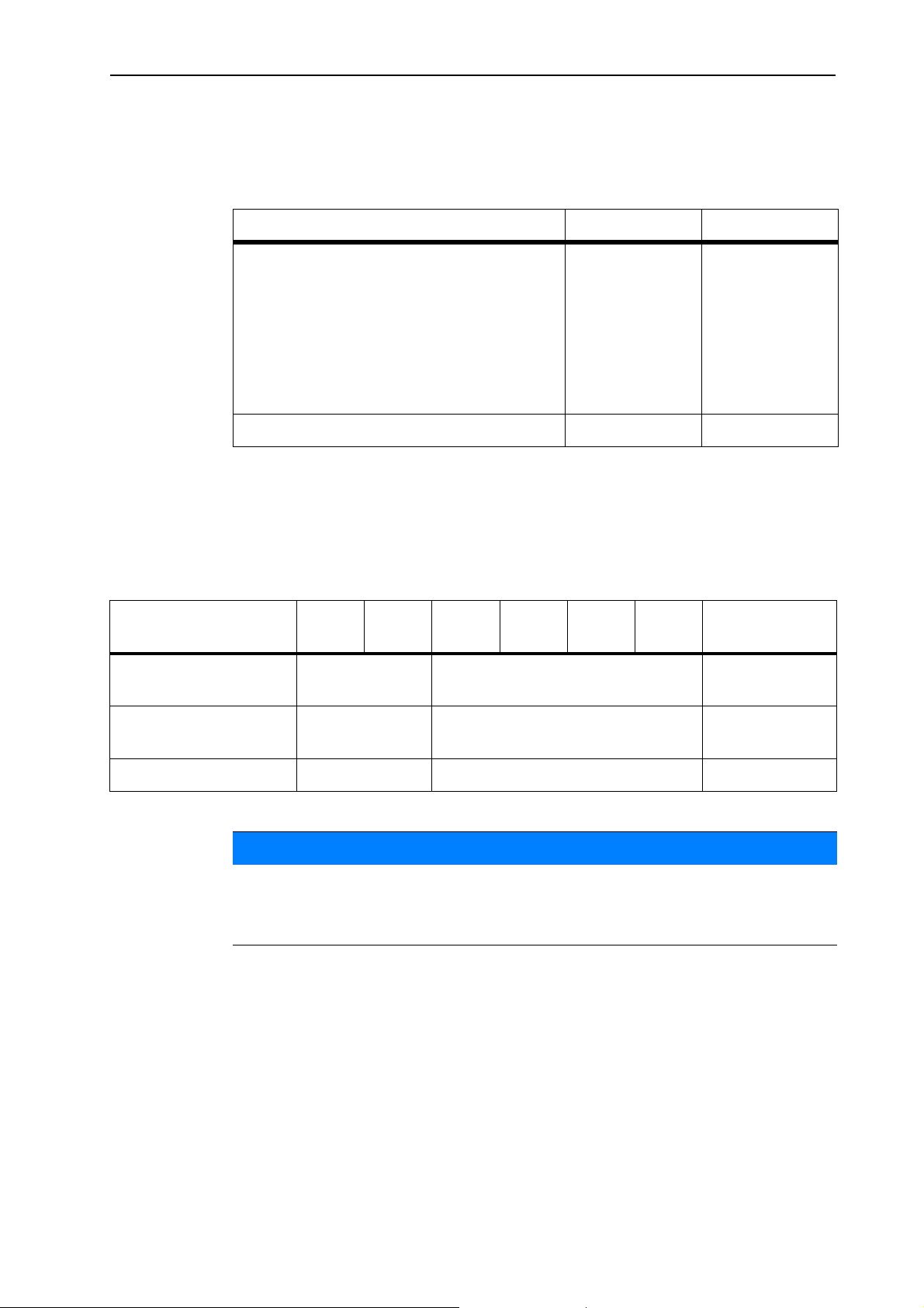
2.1 Overview of supported universal box spreaders
Function/options Type Type
Layout and function
2
Electronic application rate control
Automatic metering shaft speed control
UKS 100-Q
UKS 120-Q
UKS 150-Q
LINUS 17.1
UKS 190-Q
UKS 230-Q
UKS 300-Q
LINUS 17.1
2.2 Configuration of the control unit
The control unit is factory-set to the properties of the universal box spreader with
which it is delivered. The unit's configuration for the application rate and the operating screen depends on the area of application of the spreader.
UKS
100-Q
Area of application Winter service Fertiliser spreader Fertiliser
UKS
120-Q
UKS
150-Q
UKS
190-Q
UKS
230-Q
UKS
300-Q
LINUS
17.1
spreader
Unit of the application
g/m² kg/ha kg/ha
rate
Colour (hopper) orange red red
NOTICE
The configuration of the machine is only accessible to service personnel.
If the operating screen and the settings of the machines used do not conform,
please contact your dealer or customer service.
5
Page 12
Layout and function 2
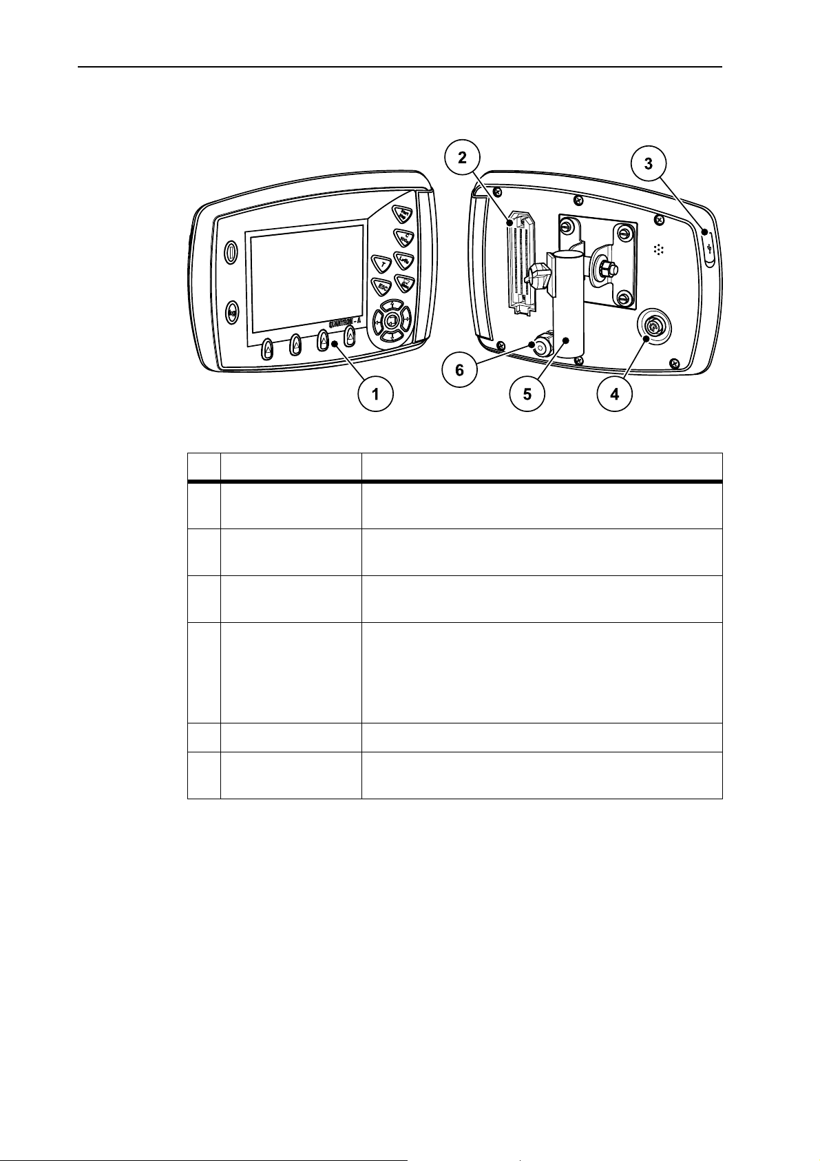
2.3 Layout of the control unit - overview
Figure 2.1: Control unit QUANTRON-A
No. Designation Function
1 Control panel Consisting of foil buttons used to operate the device
and the display for operating screens.
2 Machine cable plug
connector
39-pin plug connector for connecting the machine cable to sensors and actuators.
3 USB port with cover For exchanging data and updating the PC. Cover
serves as a protection against contamination.
4 V24 data port Serial interface (RS232) with LH 5000 and TUVR pro-
tocol, designed for Y-RS232 cables for connection to
a remote terminal.
Plug connector (DIN 9684-1/ISO 11786) for 7-pin to
8-pin cable connection for the speed sensor.
5 Mounting bracket Attaches the control unit to the tractor.
6 Power supply 3-pin plug connector conforming to DIN 9680 /
ISO 12369 for connecting the power supply.
6
Page 13
2.4 Control elements
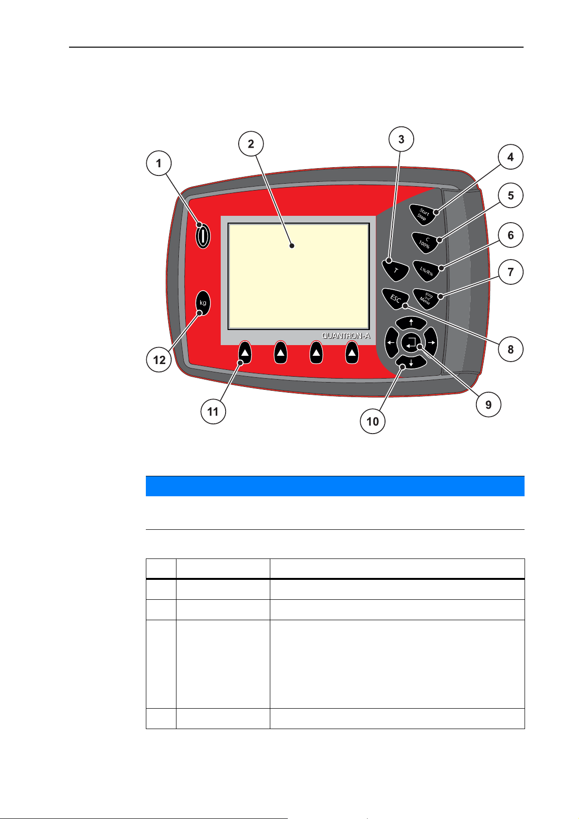
The operation of your universal box spreader is implemented via 17 foil buttons
(13 fixed and 4 freely configurable foil buttons).
Layout and function
2
Figure 2.2: Operating panel at the front of the unit
NOTICE
The operator’s manual describes the functions of the control unit QUANTRONA as of software version 2.01.00
No. Designation Function
1 ON/OFF Switches the device on/off
2 Display Display of operating screens
3T key
For spreading with simulated speed (starting at
crossing or in the headlands).
Only in g/m² configuration: for spreading with
pre-set special spreading rate (percentage value
of the additional quantity during normal spreading
operation).
4 Start/Stop Start/stop spreading.
7
Page 14

Layout and function 2
No. Designation Function
5 Clear/Reset Clearing an entry in an input field;
Acknowledging alarm messages.
Only in kg/ha configuration: Reset the excess
or shortage quantity to 100%,
6 L%/R% No function
7 Menu Switch between operating screen and main menu.
8 ESC Cancelling entries and/or returning to the previous
menu at the same time.
9
10 4 arrow keys for navigating through the menus and
Navigation field
11 Function keys F1
to F4
12 Weighing/trip
counter
Enter key
Confirming an entry
input fields.
Moving the cursor in the display
Selecting a menu or input field
Selection of the functions displayed above the function keys.
Display of the residual spreading material in the
hopper.
Trip counter
kg rest
Meter counter
8
Page 15
2.5 Display
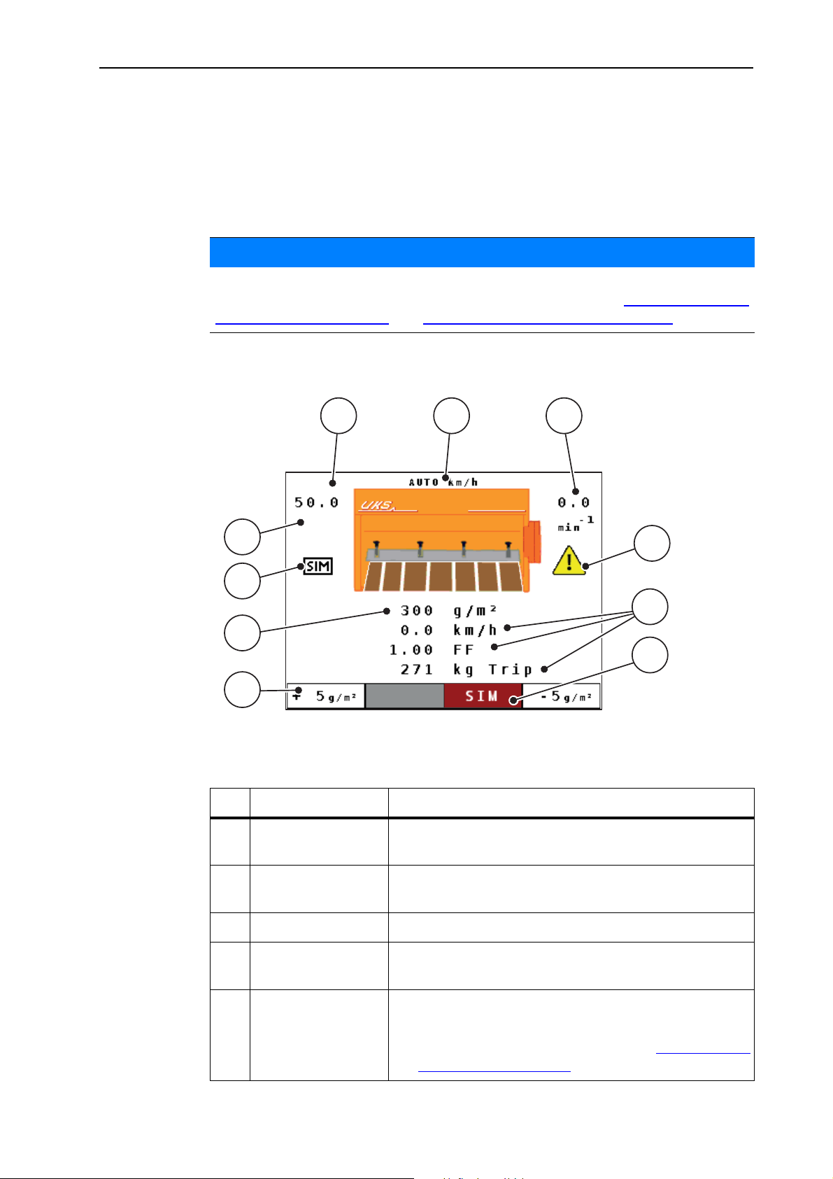
The display shows the current status information and the selection and input options for the control unit.
The most important information on the operation of the machine is displayed on
the operating screen.
NOTICE
The exact representation of the operating screen depends on the actual settings
selected as well as of the factory configuration. See chapter 2.2:
of the control unit, page 5 and 4.9.2: Display configuration, page 58.
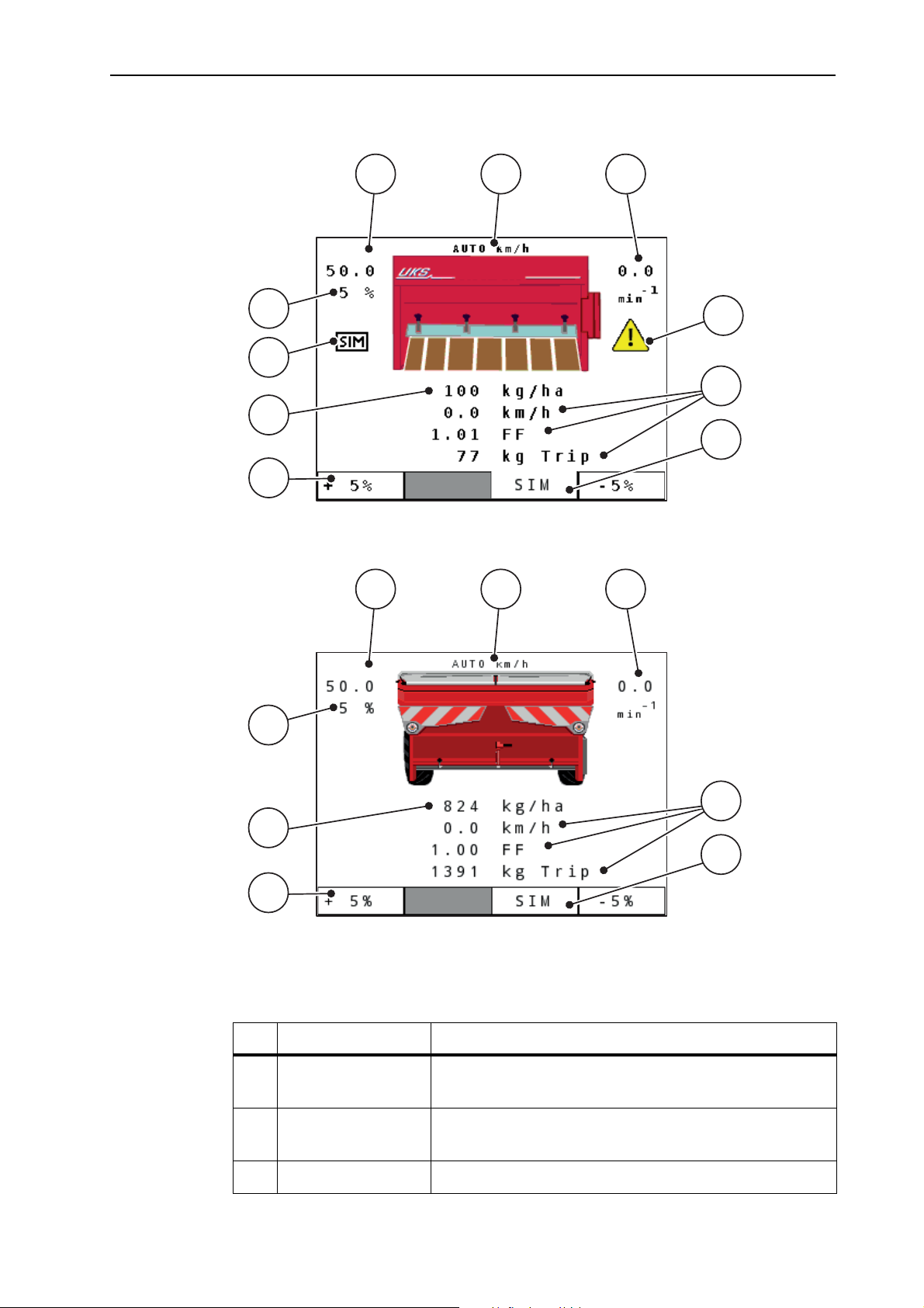
2.5.1 Operating screen of the winter spreader UKS
Layout and function
Configuration
2
1 2
130 %
10
3
4
9
5
8
6
7
Figure 2.3: Operating screen of the control unit (winter spreader UKS)
The icons and displays in the example have the following meaning:
No. Icon/display Meaning (in the example shown)
1 Metering slide
scale opening
2 Operating mode Shows the current operating mode
3 RPM Agitator shaft speed in rpm
4 Speed (rpm) warn-
ing icon
5 Display fields Configurable display fields (here: forward speed, flow
Current opening position of the metering slide
(MAN scale, MAN km/h, AUTO km/h)
The warning icon indicates that the actual rpm deviates from the selected rpm.
factor and kg trip).
Possible configuration: see chapter 4.9.2: Display
configuration, page 58.
9
Page 16
Layout and function 2
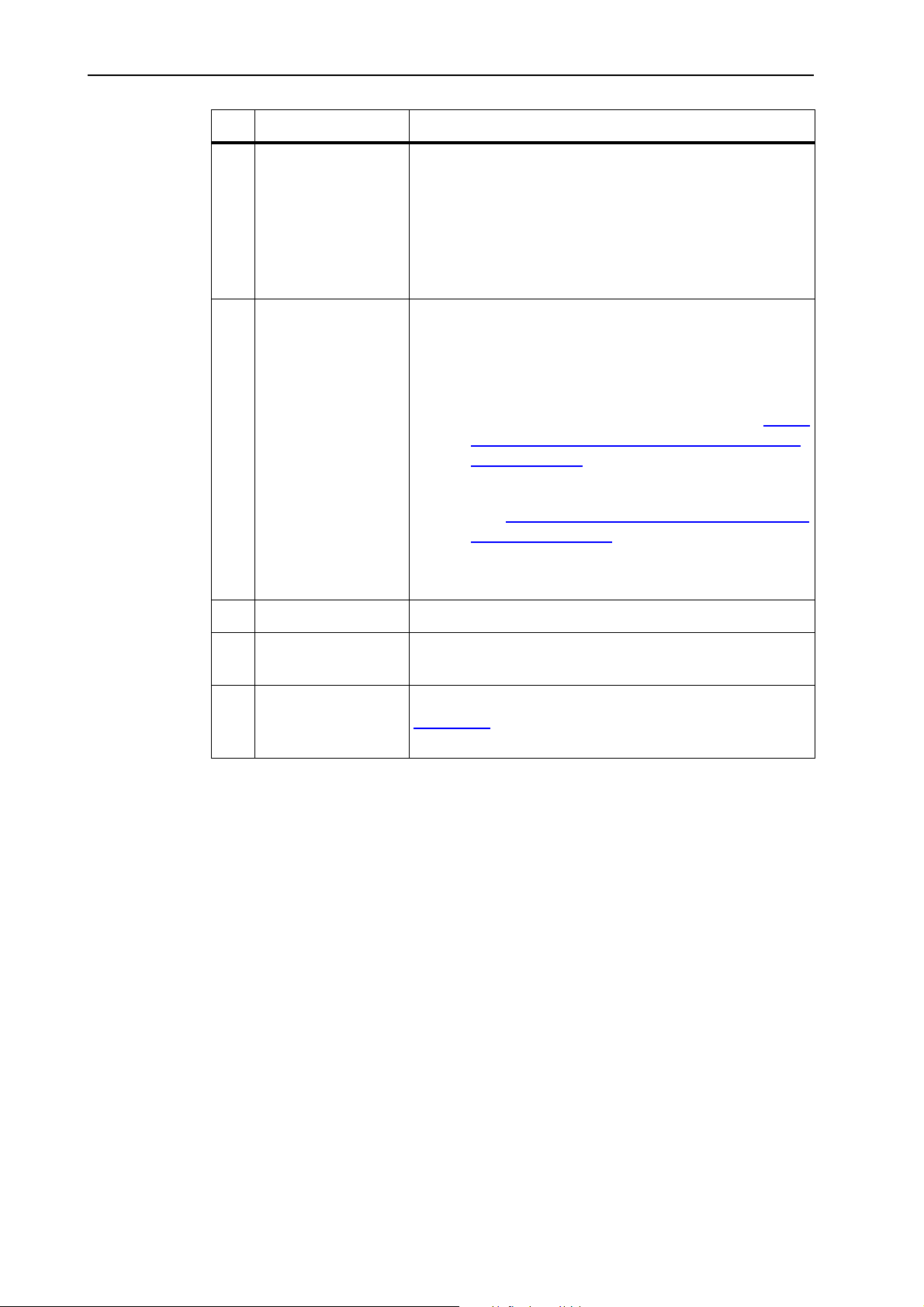
No. Icon/display Meaning (in the example shown)
6 SIM Selection of the activation type for the simulated
speed
Grey: Manual
Red: Automatic activation
Selection of the function by means of the func-
tion keys below.
7 Icon fields Icon assignment to the fields depending on the menu
Spreading density +/-
- Step width for reducing and/or increasing the
pre-set spreading density
- 4 step widths are possible, see chapter 4.5.7:
Spreading density +/- (winter spreader only
UKS), page 36
MAN +/-
- See 5.4:
Spreading in the MAN scale operat-
ing mode, page 68
Selection of the function by means of the func-
tion keys below.
8 Spreading density Preset application rate.
9 Simulated speed The symbol indicates that the simulated speed is ac-
tive.
10 Additional quantity,
special spreading
While pressing the Special spreading key (see
Figure 2.2
), the additional percentage quantity indi-
cated here is spread.
10
Page 17
Layout and function
7
1 2
3
10
6
5
8
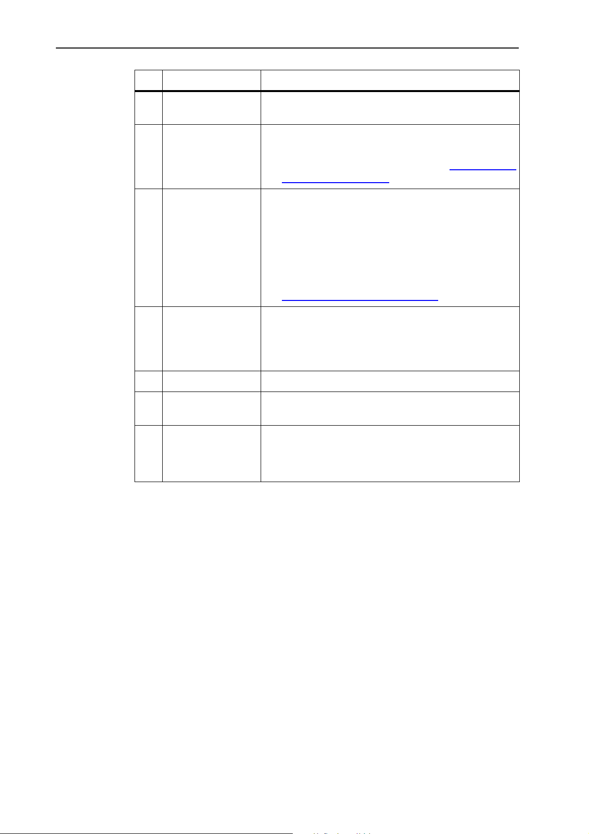
2.5.2 Operating screen of the UKS GB and LINUS fertiliser spreaders
2
1 2
10
3
4
9
5
8
6
7
Figure 2.4: Operating screen of the control unit (example: UKS operating
screen)
Figure 2.5: Operating screen of the control unit (example: LINUS operating
The icons and displays in the example have the following meaning:
No. Icon/display Meaning (in the example shown)
1 Metering slide
2 Operating mode Displays the current operating mode (MAN scale,
3 RPM Agitator shaft speed in rpm
screen)
scale opening
Current opening position of the metering slide
MAN km/h, AUTO km/h)
11
Page 18
Layout and function 2
No. Icon/display Meaning (in the example shown)
4 Speed (rpm) warn-
ing icon
The warning icon indicates that the actual rpm deviates from the selected rpm.
5 Display fields Configurable display fields (here: forward speed, flow
factor and kg trip).
Possible configuration: see chapter 4.9.2: Display
configuration, page 58.
6 SIM Selection of the activation type for the simulated
speed.
Grey: Manual
Red: Automatic activation
Selection of the function by means of the func-
tion keys below.
4.6.6: Simulated speed, page 48
7 +/- additional quan-
tity
Percentage value (+/-) for application rate adjustment
of the pre-set application rate
Selection of the function by means of the func-
tion keys below.
8 Application rate Preset application rate.
9 Simulated speed The symbol indicates that the simulated speed is ac-
tive.
10 Application rate ad-
justment
Application rate adjustment (+/-) in percent
Display of application rate adjustment
Value ranges of +/- 1 to 99% possible
12
Page 19
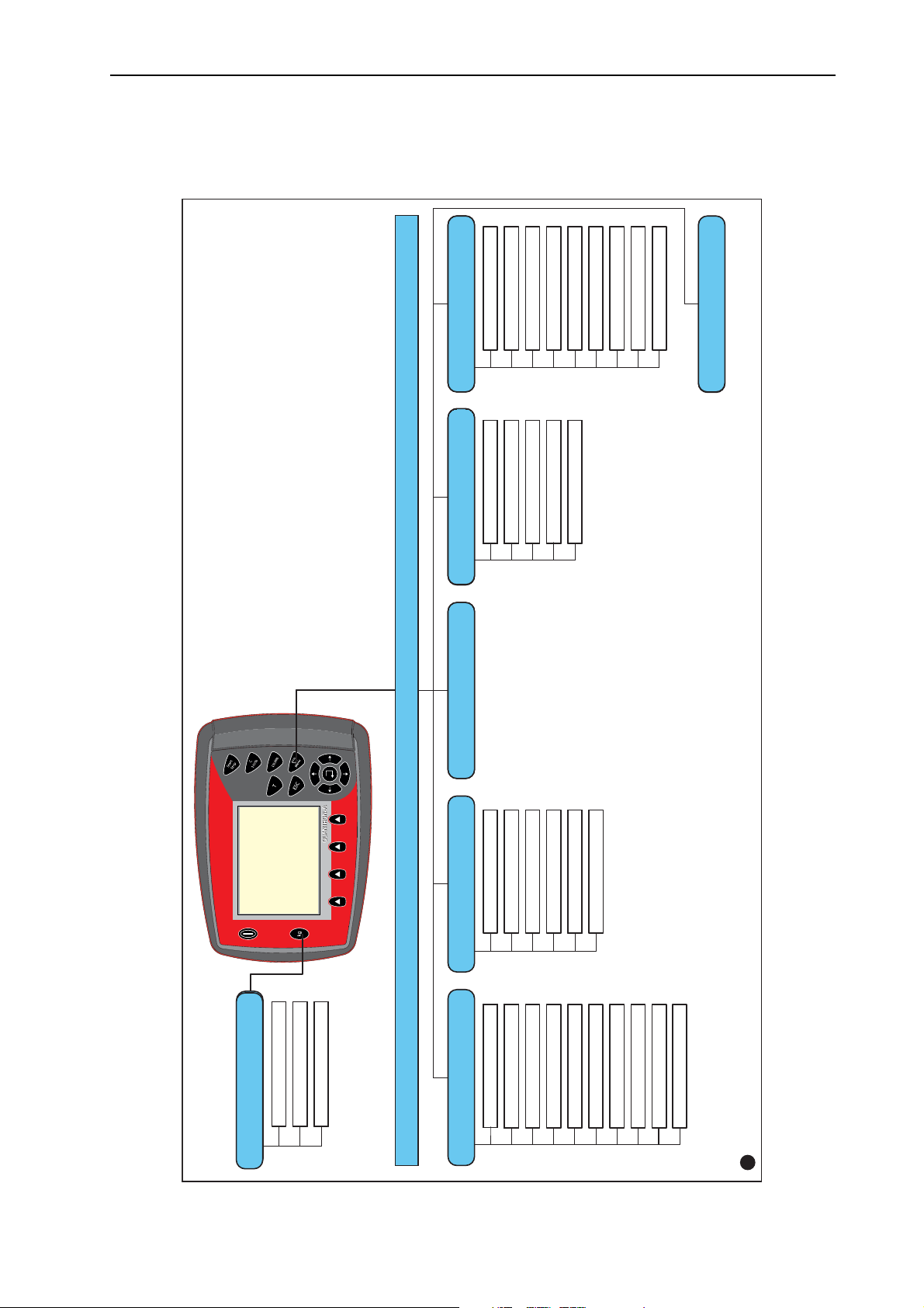
2.6 Structural menu overview
QA UKS 2.01.00
Info
Metre counter
kg rest (kg, ha, m)
Trip counter (km/h)
Weighing - Tripcounter
Machine settings
Field data
Info
Fast emptying System / Test
Main menu
Brightness
Languages
Display config.
Test/Diagnosis
Date
Time
Data transmission
Total data counter
Service
AUTO/MAN mode
Working width
Tractor calibration
Special spreading (+%)
Slider openings
Simulated speed
Flow factor
Spreading dens. (g/m²)
RPM
Spreading material name
Spreading material
Start calibration
Manufacturer
Composition
Fertiliser chart
Spreading density +/-
Spreading mat. settings
Choose file
Create file
Erase file
Erase all files
Import/Export
en
2.6.1 Winter spreader UKS series
Layout and function
2
13
Page 20
Layout and function 2
QA UKS GB/LINUS 2.01.00
Manufacturer
Composition
Fertiliser chart
'+/- appl. rate (%)
Fertiliser settings Machine settings
Field dataFast emptying System / Test
Brightness
Languages
Display config.
Test/Diagnosis
Date
Time
Data transmission
Total data counter
Service
Main menu
Meter counter
Rest (kg, ha, m)
Tractor (km/h)
AUTO/MAN mode
en
Trip counter(km/h)
Application rate
Spreading material
Flow factor
Start calibration
RPM
Working width
Slider openings
Simulated speed
Choose file
Create file
Erase file
Erase all files
Import/Export
Weighing/Trip count.
Info
Fertiliser name
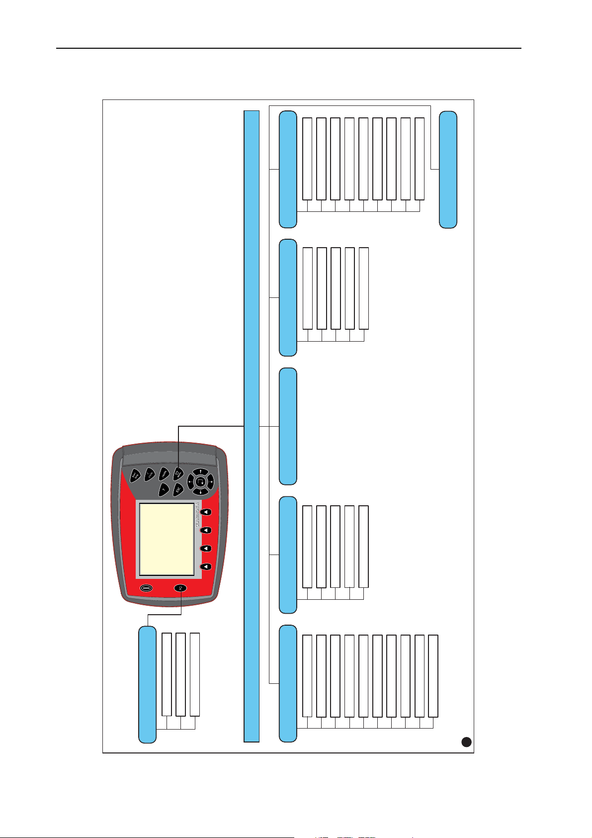
2.6.2 UKS GB and LINUS series fertiliser spreaders
14
Page 21
3 Attachment and installation
3.1 Requirements for the tractor
Before installing the control unit, check to make sure your tractor meets the following requirements:
A minimum voltage of 11 V is essential at all times, even if multiple loads are
connected simultaneously (e. g. air conditioning system, lights).
The PTO speed can be set to 540 rpm and must be maintained (basic re-
quirement for correct working width).
On tractors without load-switchable gears, the forward speed must be selected
by using the correct gear ratio in such a way that it corresponds to a PTO speed
of 540 rpm.
A 7-pin socket (DIN 9684-1/ISO 11786). The control unit receives the pulse
for the current forward speed through this socket.
NOTICE
Attachment and installation
3
The 7-pin socket for the tractor and the forward speed sensor can be obtained
as an expansion kit (option), see chapter Special Equipment.
3.2 Connections, sockets
3.2.1 Power supply
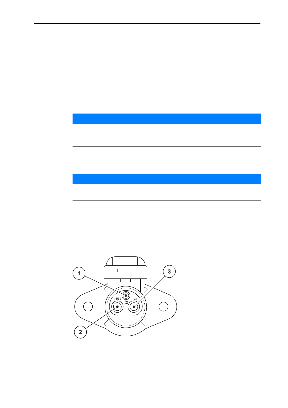
The control unit is supplied with power from the tractor via the 3-pin power supply
socket (DIN 9680/ISO 12369).
NOTICE
Figure 3.1: PIN assignment of power socket
[1] PIN 1: not required
[2] PIN 2: (15/30): +12 V
[3] PIN 3: (31): mass
15
Page 22

Attachment and installation 3
3.2.2 7-pin plug connector
The control unit receives the pulses for the current forward speed via the 7-pin
plug connector 9684-1/ISO 11786). For this purpose, the 7-pin to 8-pin cable (accessory) is connected to the forward speed sensor at the plug connector.
[1] PIN 1: actual forward speed (radar)
[2] PIN 2: theoretical forward speed (e. g. gear-
box, wheel sensor)
Figure 3.2: PIN assignment for 7-pin plug connector
16
Page 23

3.3 Connecting the control unit
After having switched on the QUANTRON-A control unit, the display shows the
machine name for a short time.
Observe the machine type
The QUANTRON-A control unit has been calibrated at the factory for the universal box spreader with which it was supplied.
Check the machine type in the Info menu. Refer to 4.10: Info, page 61.
Connect the control unit to the correct universal box spreader only.
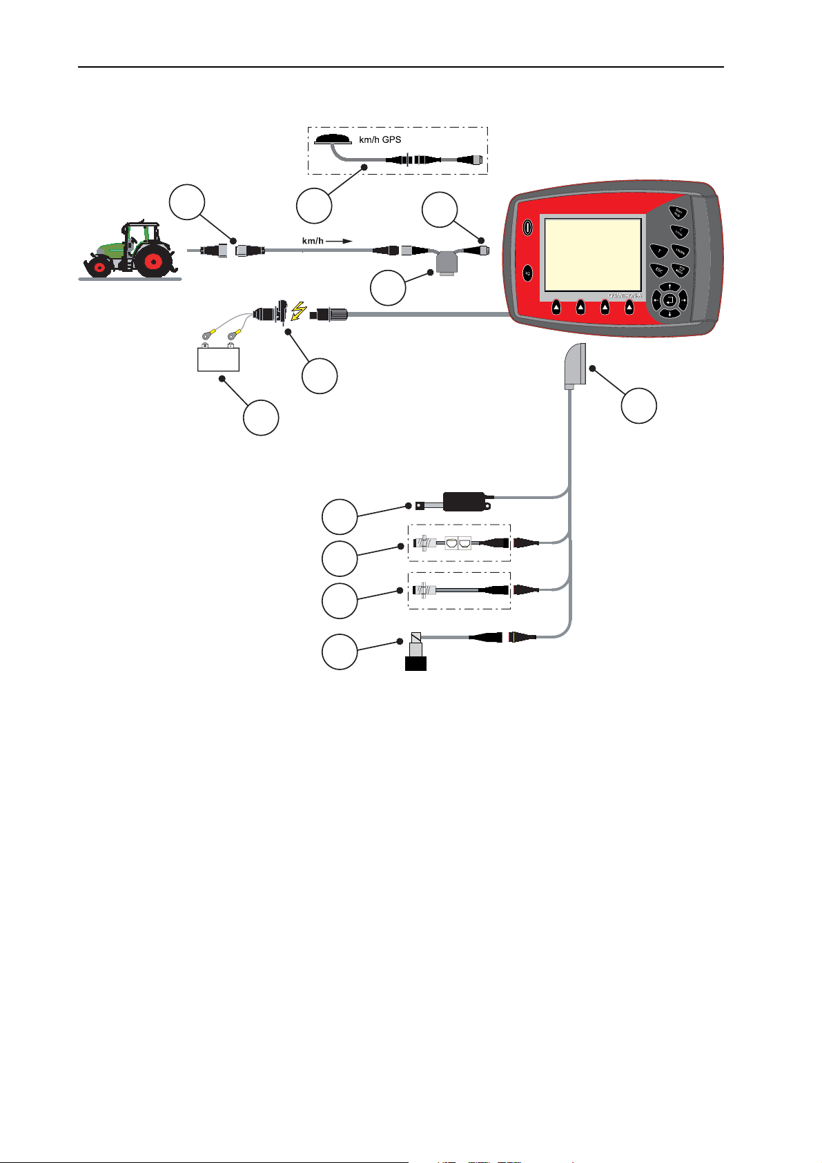
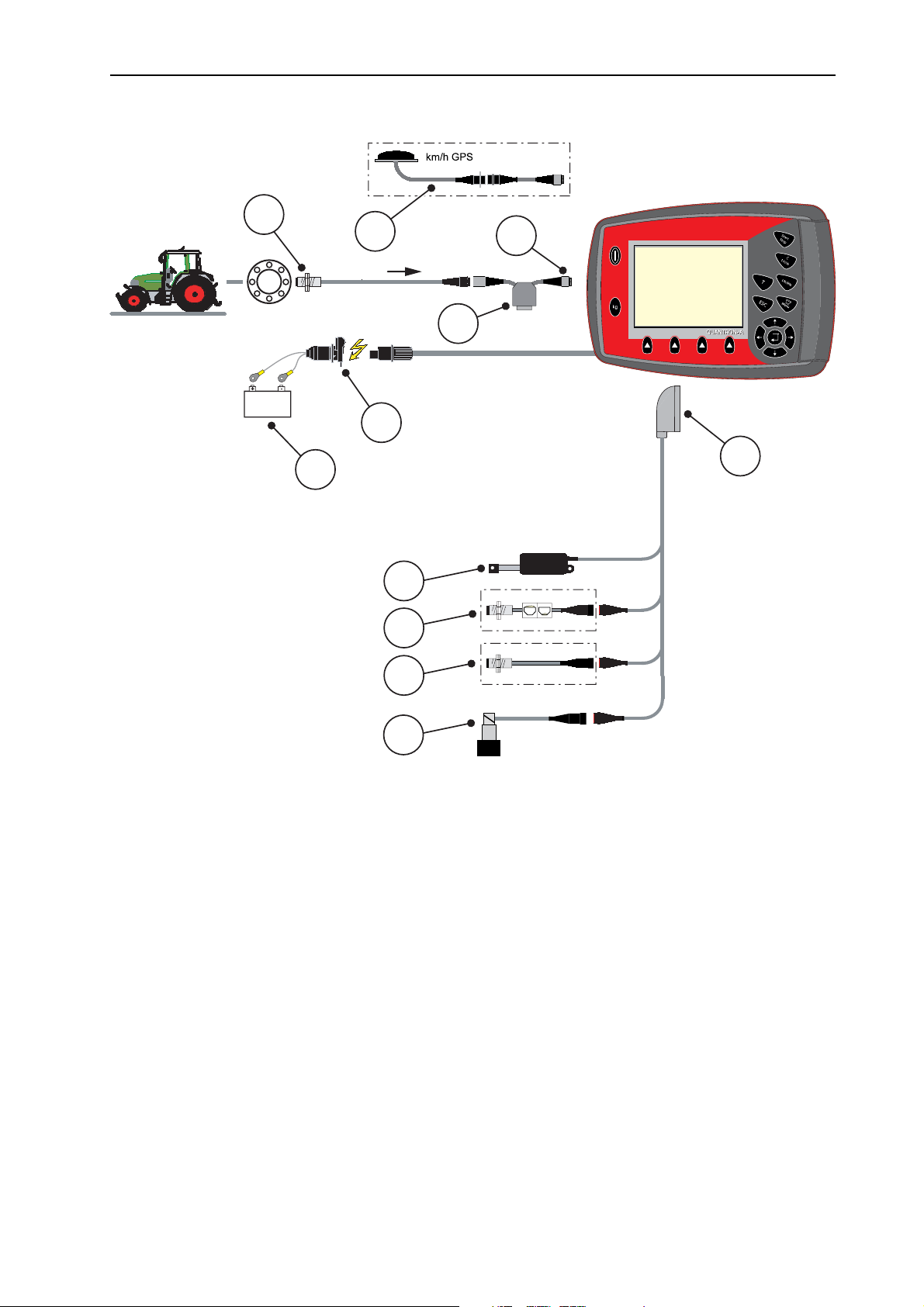
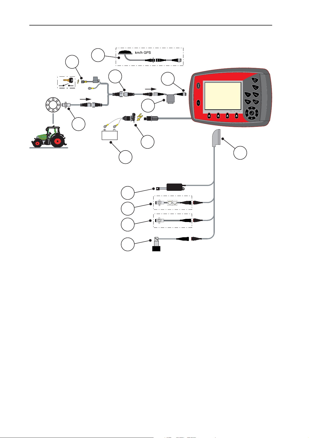
Depending on the equipment, there are different methods of attaching the control
unit to the machine. Schematic connection diagrams can be obtained from the
following figures:
NOTICE
NOTICE
Attachment and installation
3
Standard connection: page 18,
Connection with wheel sensor: page 19,
Connection with wheel sensor and machine cable: page 20.
Proceed in the following order.
Select a suitable position in the tractor cabin (within the driver's field of vi-
sion) to fix the control unit.
Fix the control unit using the mounting bracket in the tractor cabin.
Connect the control unit to the 7-pin socket or to the forward speed sensor
(depending on the equipment, see figure 3.3
Connect the control unit to the sensors and the actuator of the universal box
to figure 3.5).
spreader using the 39-pin machine cable.
Connect the control unit to the tractor's power supply using the 3-pin plug con-
nector.
17
Page 24
Attachment and installation 3
Standard schematic connection diagram:
10
11
1
9
8
2
7
3
4
5
6
Figure 3.3: Schematic connection diagram QUANTRON-A (standard)
[1] Serial interface RS232, 8-pin plug connector
[2] 39-pin machine plug
[3] Metering slide actuator
[4] Level sensor (option)
[5] Agitator shaft speed sensor
[6] LINUS: Proportional valve, agitator shaft speed
[7] Battery
[8] 3-pin plug connector conforming to DIN 9680 / ISO 12369
[9] Option: Y-cable (V24 RS232 interface for storage medium)
[10] 7-pin plug connector conforming to DIN9684
[11] Option: GPS cable and receiver
18
Page 25
Attachment and installation
Schematic connection diagram for wheel sensor:
10
11
km/h
1
9
8
3
7
2
3
4
5
6
Figure 3.4: Schematic connection diagram QUANTRON-A (standard)
[1] Serial interface RS232, 8-pin plug connector
[2] 39-pin machine plug
[3] Metering slide actuator
[4] Level sensor (option)
[5] Agitator shaft speed sensor
[6] LINUS: Proportional valve, agitator shaft speed
[7] Battery
[8] 3-pin plug connector conforming to DIN 9680 / ISO 12369
[9] Option: Y-cable (V24 RS232 interface for storage medium)
[10] Forward speed sensor
[11] Option: GPS cable and receiver
19
Page 26
Attachment and installation 3
km/h
km/h
6
1
2
3
5
7
8
11
10
12
4
9
13
Standard schematic connection diagram for machine cable:
Figure 3.5: Schematic connection diagram QUANTRON-A (standard)
[1] Serial interface RS232, 8-pin plug connector
[2] 39-pin machine plug
[3] Metering slide actuator
[4] Level sensor (option)
[5] Agitator shaft speed sensor
[6] LINUS: Proportional valve, agitator shaft speed
[7] Battery
[8] 3-pin plug connector conforming to DIN 9680 / ISO 12369
[9] Option: Y-cable (V24 RS232 interface for storage medium)
[10] 7-pin plug connector conforming to DIN9684
[11] Forward speed sensor
[12] Option: Power supply QUANTRON-A via ignition lock
[13] Option: GPS cable and receiver
20
Page 27
4 Operation QUANTRON-A
Risk of injury due to ejected spreading material
In the case of a fault, it is possible that the metering slide unexpectedly opens during road transport to the spreading location.
There is a danger of slipping and injury of persons due to ejected
spreading material.
Before leaving for the place of spreading the electronic
control unit QUANTRON-A must always be switched off.
4.1 Switching on the control unit
Requirements:
The control unit is correctly connected to the machine and the tractor (for ex-
ample, see chapter 3.3:
A minimum voltage of 11 V is guaranteed.
Operation QUANTRON-A
Connecting the control unit, page 17).
4
NOTICE
The operator’s manual describes the functions of the control unit QUANTRONA as of software version 2.01.00
1. Press the ON/OFF switch.
After a few seconds, the start-up screen of the control unit appears.
Shortly after, the control unit will display the activation menu for a few
seconds.
2. Press the Enter key.
The start diagnosis will be displayed for a few seconds.
Afterwards, the operating screen is displayed.
21
Page 28
Operation QUANTRON-A 4
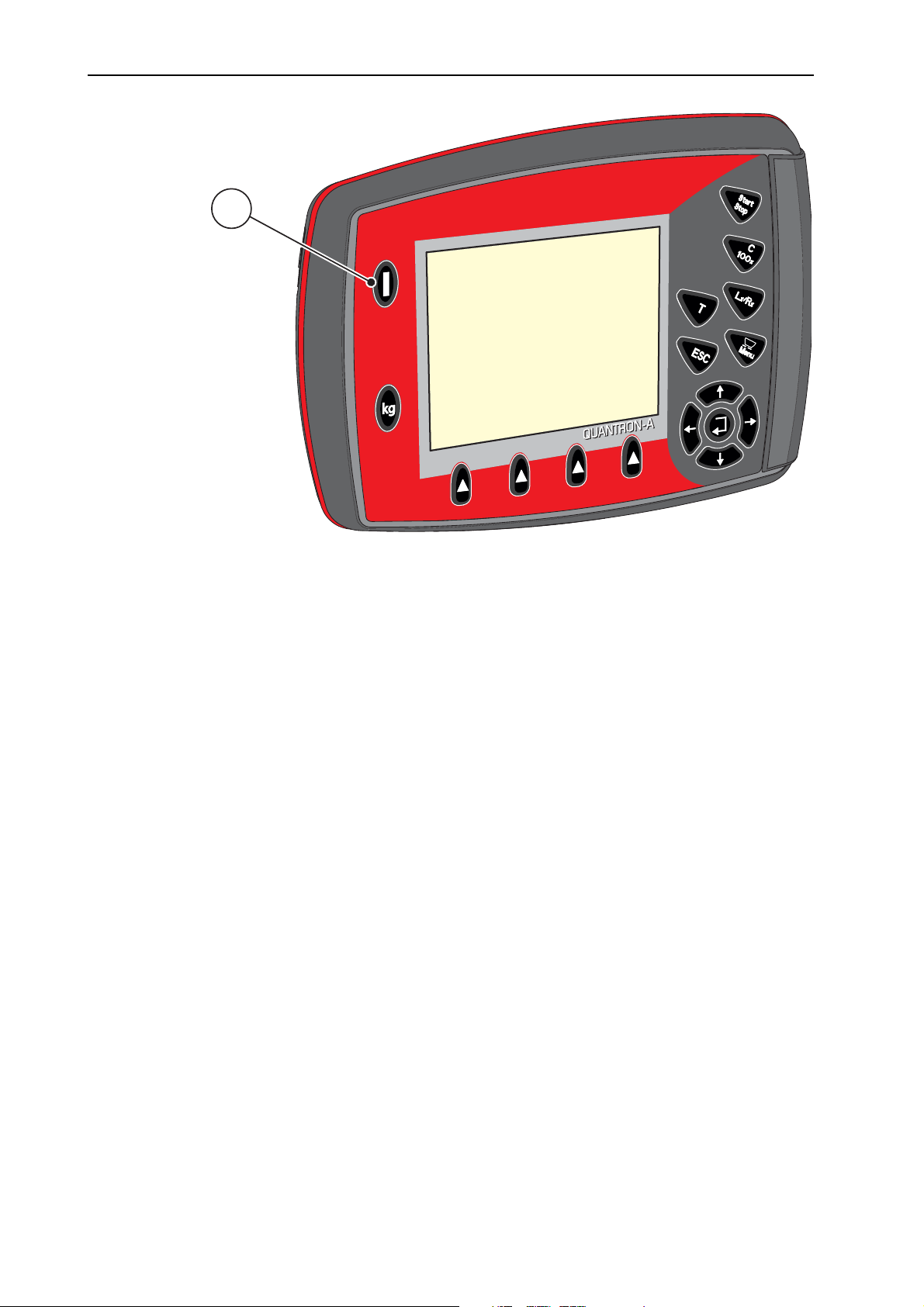
1
Figure 4.1: Start QUANTRON-A
[1] ON/OFF switch
22
Page 29
4.2 Menu navigation
NOTICE
Operation QUANTRON-A
4
Please refer to chapter 1.2.5:
Menu hierarchy, keys and navigation, page 3 for
important notes regarding the display and navigation between menus.
Accessing the main menu
Press the Menu key. Refer to 2.4: Control elements, page 7.
The main menu is displayed.
The black bar indicates the first sub-menu.
NOTICE
Not all parameters are displayed simultaneously in one menu window. The arrow keys enable switching to the next or previous windows.
Accessing a sub-menu:
1. Move the bar up and down with the arrow keys.
2. Highlight the desired sub-menu with the bar on the display.
3. Access the highlighted sub-menu by pressing the Enter key.
Windows appear prompting various actions.
Text input; see 4.11.1: Text input, page 62
Value input; see 4.11.2: Entering values with the cursor keys, page 64
Settings made in further sub-menus
Exiting the menu
Confirm settings by pressing the Enter key.
The previous menu is displayed.
or
press the ESC key.
The previous settings are retained.
The previous menu is displayed.
Press the Menu key.
The operating screen is displayed again.
Press the Menu key once more to return to the menu that you left.
23
Page 30
Operation QUANTRON-A 4
4.3 Weighing trip counter
This menu provides values on the spreading work carried out.
Press the kg key at the control unit.
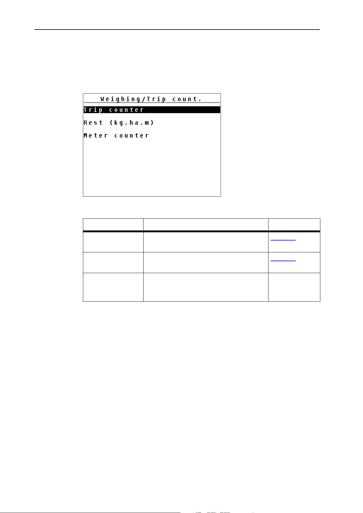
The weighing trip counter menu is displayed.
Figure 4.2: Weighing/Trip counter menu
Sub-menu Meaning Description
Trip counter Display of the applied spreading quantity,
Page 25
area spread and spread distance.
Rest (kg, ha, m) Display of the residual spread quantity,
Page 26
area and distance.
Meter counter Display of the distance travelled since the
last reset of the meter counter.
Reset (zeroing)
by pressing the
C 100% key
24
Page 31
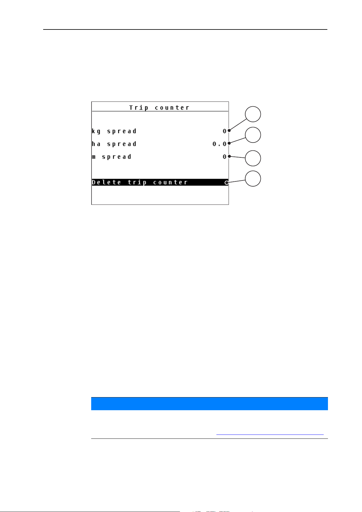
4.3.1 Trip counter
1
2
4
3
This menu provides the following values:
- spread quantity (kg)
- spread area (ha)
- spread distance (m)
Operation QUANTRON-A
4
Figure 4.3: Trip counter menu
[1] Display of spread quantity since the last reset
[2] Display of spread area since the last reset
[3] Display of spread distance since the last reset
[4] Clearing the trip counter: all values to 0
Delete trip counter:
1. Open the Weighing/Trip counter > Trip-counter sub-menu.
The calculated values for spread quantity, area and distance since the
last deletion are displayed.
The Delete trip counter field is highlighted.
2. Press the Enter key.
All values of the trip counter are reset to 0.
3. Press the kg key.
The operating screen is displayed again.
Checking the trip counter during spreading:
During the spreading work, i.e. with the metering slide being open, change into
the Trip counter menu and obtain the current values there.
NOTICE
If the values are to be permanently monitored during spreading, freely assignable display fields in the operating screen may also be assigned the kg Trip,
ha Trip or mTrip values, refer to chapter 4.9.2:
Display configuration, page 58.
25
Page 32
Operation QUANTRON-A 4
1
2
4
5
3
4.3.2 Residual material
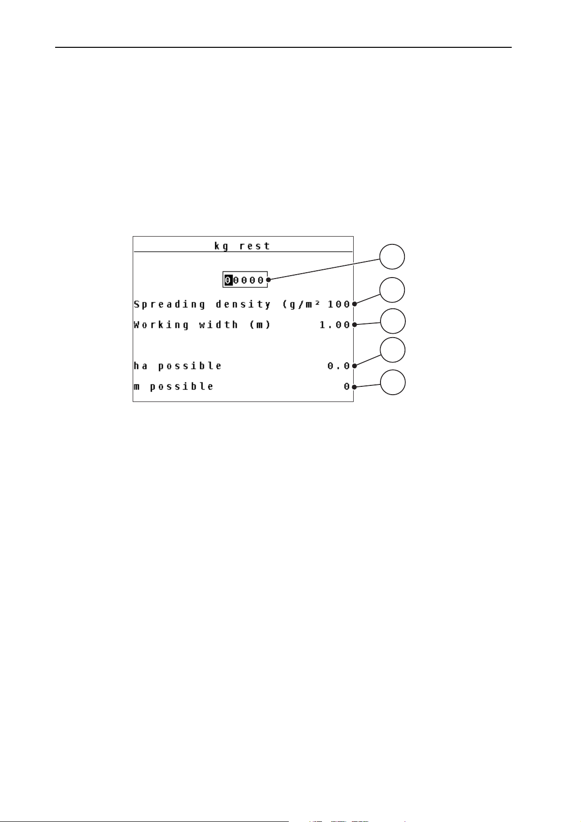
In the Rest (kg, ha, m) menu, you can query or input the residual material in the
hopper.
The menu indicates the possible area (ha) and distance (m) which can still be
spread with the residual material. Both displays are calculated based on the following values:
Fertiliser settings/spreading material settings
- Application rate/spreading density
- Working width
- Weight (entered)
Figure 4.4: Rest (kg, ha, m) menu, example winter spreader UKS
[1] Residual material input field
[2] Application rate in kg/ha and/or spreading density in g/m² (display field from fertiliser
settings, depending on type)
[3] Working width (display field from fertiliser settings)
[4] Display of possible area that can be spread with the residual material
[5] Display of possible distance that can be spread with the residual material
26
Page 33

Operation QUANTRON-A
Entering the residual material when refilling:
1. Open the Weighing trip counter > Rest (kg, ha, m) menu.
The residual material from the last spreading process is displayed.
2. Fill the hopper.
3. Enter the new total weight of the spreading material in the hopper.
The device calculates the values for the possible spread area and the
possible spread distance.
NOTICE
The values for application rate/spreading density and working width cannot be
changed in this menu. They are for information purposes only.
4. Press the kg key.
The operating screen is displayed again.
Calling up the residual material during spreading:
4
During spreading, the residual material is continuously recalculated and displayed.
During spreading, i.e. with the metering slide being open, the kg rest menu can
be opened to display the residual material currently present in the hopper.
NOTICE
If the values are to be permanently monitored during spreading, freely assignable display fields in the operating screen can also be assigned with the kg rest,
ha rest or m rest values, refer to chapter 4.9.2:
Display configuration, page 58.
27
Page 34
Operation QUANTRON-A 4
4.4 Main menu
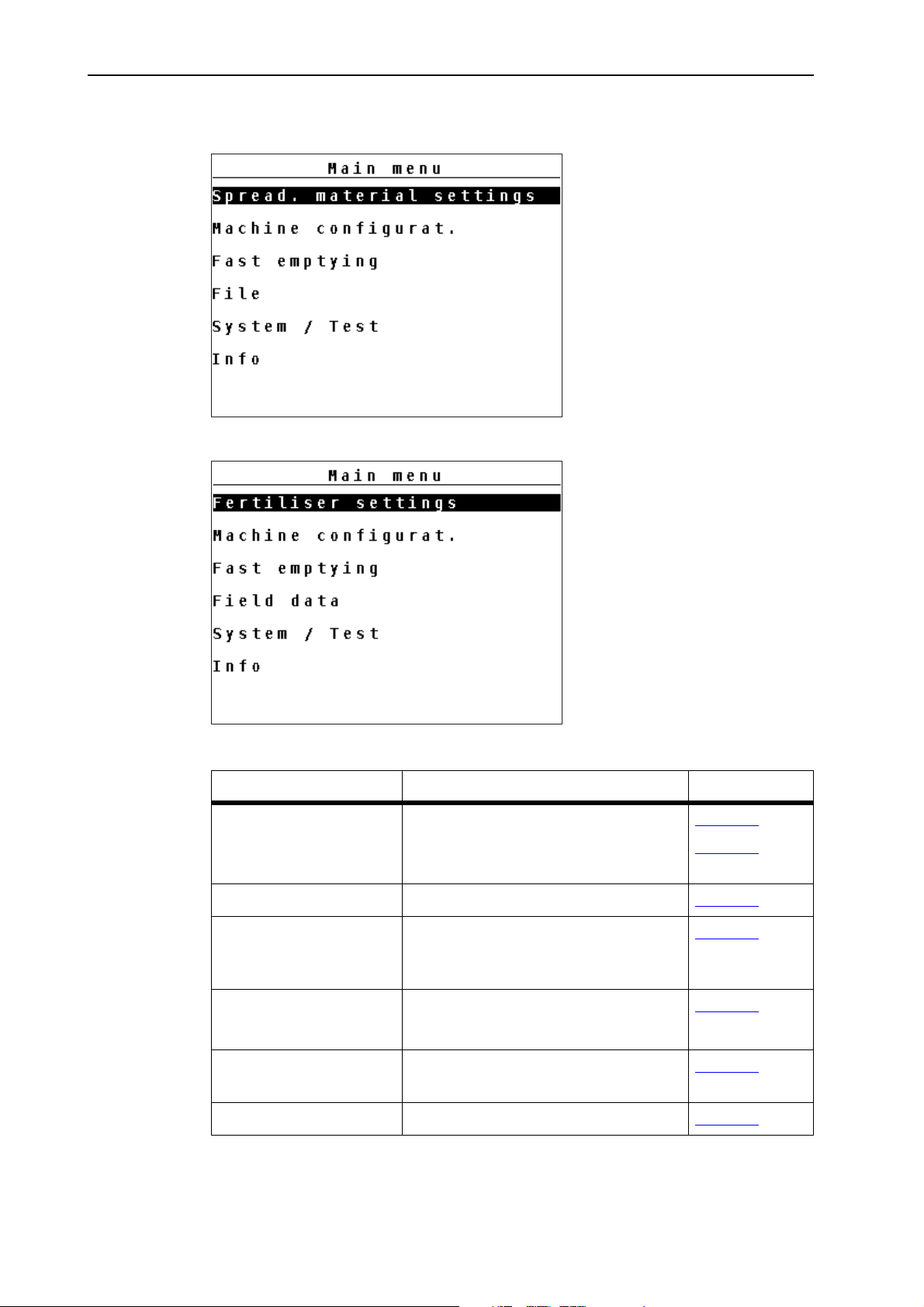
Figure 4.5: Main menu QUANTRON-A (Winter spreaders UKS)
Figure 4.6: Main menu QUANTRON-A (Fertiliser spreaders)
Sub-menu Meaning Description
Spread. material settings
Settings of the spreading operation. Page 29
Page 31
Fertiliser settings
Machine configurat. Settings for tractor and machine. Page 40
Fast emptying Direct access to the menu for fast
Page 50
emptying of the universal box
spreader.
File
Field data
System/Test Settings and diagnosis of the control
Opens the menu for selecting, creating or deleting a file.
Page 51
Page 56
unit.
Info Machine configuration display Page 61
28
Page 35
Operation QUANTRON-A
4.5 Spreading material settings
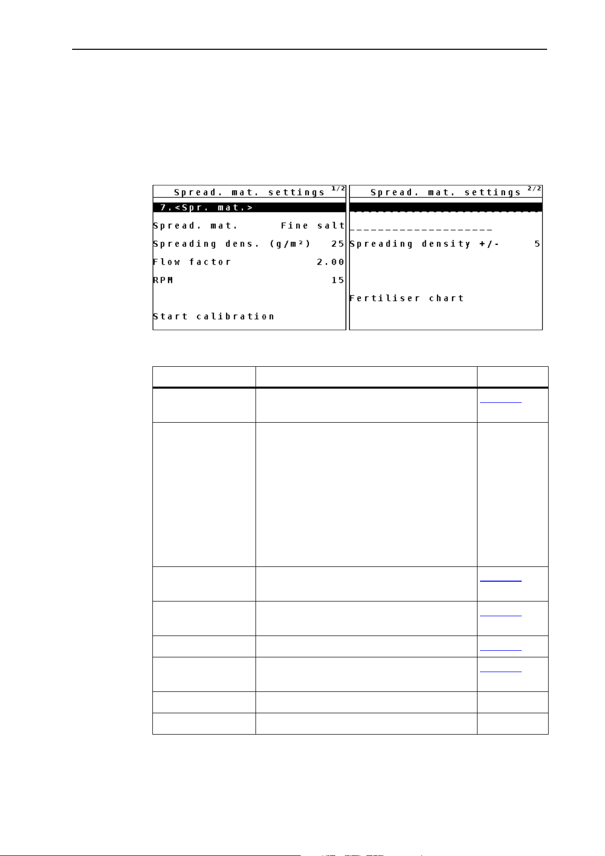
You can adjust the settings for spreading material and spreading operation in this
menu.
4.5.1 Spreading material settings for winter spreaders menu UKS
Open the Main menu > Spread. mat. settings menu.
4
Figure 4.7: Spreading material settings menu, page 1 and 2
Sub-menu Meaning/possible values Description
Spreading material
name
Manual entry of the name of a new spreading material.
Page 38
Spreading material Selection of a spreading material or fertiliser
type for determining the mass current curve:
Fertiliser
Salt, fine
Salt, coarse
Salt, damp
Sand
Grit
Spreading density Entering of the spreading density based on
Page 32
the pre-selected characteristic curve.
Flow factor Entry of the flow factor for the spreading ma-
Page 33
terial used.
RPM Selection of the agitator shaft speed Page 34
Start of calibration
test
Manufacturer
Implementation of the calibration test and
new calculation of the flow factor.
Entry of the spreading material manufacturer.
Page 34
Composition Percentage of the chemical composition.
29
Page 36
Operation QUANTRON-A 4
Sub-menu Meaning/possible values Description
Spreading density
+/-
Specification of the step width by which the
spreading density can be manually in-
Page 36
creased or decreased later.
Fertiliser chart Management of fertiliser charts. Page 38
NOTICE
Not all parameters are displayed simultaneously in one menu window. The arrow keys enable switching to the next or previous windows.
30
Page 37
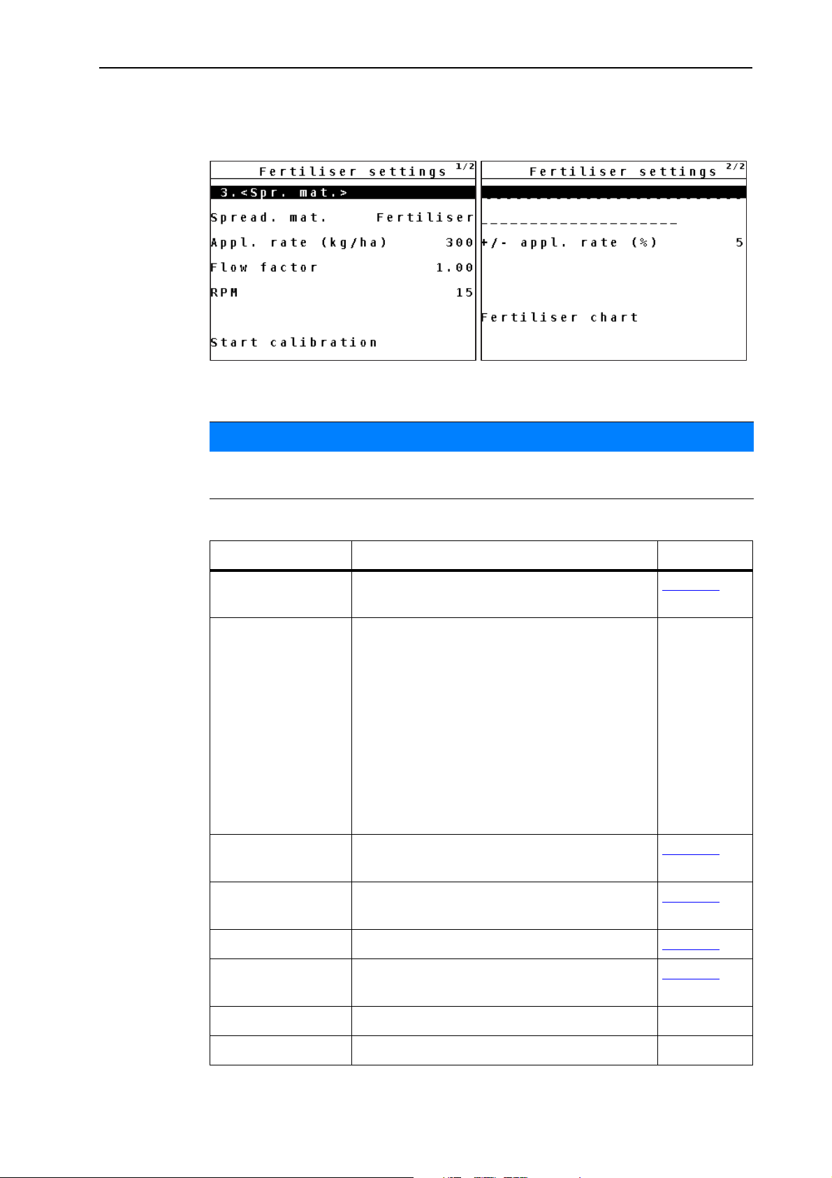
4.5.2 Fertiliser settings for fertiliser spreaders menu
Open the Main menu > Fertiliser settings menu.
Figure 4.8: Fertiliser settings menu, page 1 and 2
NOTICE
Operation QUANTRON-A
4
Not all parameters are displayed simultaneously in one menu window. The arrow keys enable switching to the next or previous windows.
Sub-menu Meaning/possible values Description
Fertiliser name Manual entry of a name for a new type of fer-
Page 38
tiliser.
Spreading material Selection of one of six spreading material or
fertiliser types for determining the mass flow
characteristic:
Fertiliser
Salt, fine
Salt, coarse
Salt, damp
Sand
Grit
Application rate Input of target value for the application rate
Page 32
in kg/ha.
Flow factor Entry of the flow factor for the spreading ma-
Page 33
terial used.
RPM Selection of the agitator shaft speed Page 34
Start of calibration
test
Implementation of the calibration test and
new calculation of the flow factor.
Page 34
Manufacturer Entry of the fertiliser manufacturer.
Composition Percentage of the chemical composition.
31
Page 38
Operation QUANTRON-A 4
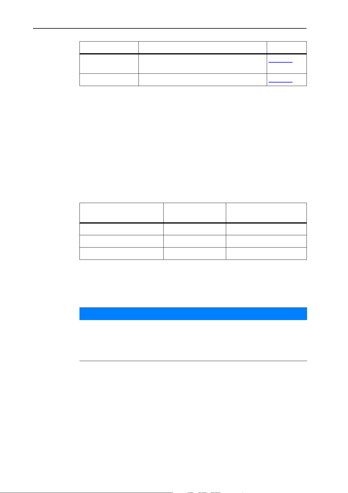
Sub-menu Meaning/possible values Description
+/- quantity Pre-setting the quantity reduction for the dif-
ferent spreading types.
Fertiliser chart Management of fertiliser charts. Page 38
4.5.3 Spreading density/application rate
In the Spreading density (UKS winter services) or Application rate (UKS GB
and LINUS) the required spreading density/application rate with which the
spreading material is to be applied can be entered.
Entry of spreading density/application rate:
1. Open Spread. mat. settings > Spreading density or Fertiliser settings >
Application rate.
The currently applicable spreading density or application rate is dis-
played.
2. Enter a new value in the input field using the arrow keys:
Spreading material
(property)
Salt, coarse/fine (damp) 5-40 50-400
Spreading density
2
)
(g/m
Page 37
Application rate (kg/ha)
Sand, grit (blunting) 75-300 750-3000
Fertiliser 1-300 1-3000
3. Press the Enter key.
The new value is saved in the control unit.
The Spread. mat. settings menu is displayed.
NOTICE
The programmed ranges are only reference values. The spreading density
can be adapted to individual requirements.
If a value outside the range is entered, an alarm message is displayed.
Press the C/100% key: the entered value is saved.
32
Page 39

4.5.4 Flow factor
The range of the flow factor depends on the set agitator shaft speed.
between 0.4 to 2.5 with an agitator shaft speed of 15 rpm
between 0.4 to 3.5 with an agitator shaft speed of 28 rpm
For identical basic settings (km/h/, working width, kg/ha or g/m²) the following applies:
If the flow factor is increased, the application rate is decreased.
If the flow factor is decreased, the application rate is increased.
If the flow factor is known from earlier calibration tests or from the fertiliser chart,
it can be entered manually in this menu.
Via the Calibration test menu, the flow factor can be determined and entered by
means of the QUANTRON-A. Refer to 4.5.6:
NOTICE
Operation QUANTRON-A
Calibration test, page 34.
4
NOTICE
The flow factor calculation depends on the operating mode used. For further information about the flow factor, refer to chapter 4.6.2:
AUTO/MAN mode, page
44.
Entering the flow factor:
1. Open the Fertiliser/Spread. mat. settings > Flow factor menu.
The currently applied flow factor is displayed.
2. Enter the new value in the input field.
NOTICE
If your spreading material is not listed in the fertiliser chart, enter a flow factor of
1.00.
In the AUTO km/h and MAN km/h operating modes, we highly recommend
executing a calibration test in order to be able to accurately determine the flow
factor for this fertiliser.
3. Press the Enter key.
The new value is saved in the control unit.
33
Page 40

Operation QUANTRON-A 4
4.5.5 RPM
In this menu, the agitator shaft speed is entered. If an universal box spreader LINUS is used, the control unit controls the agitator shaft speed via the proportional
valve.
NOTICE
UKS only: The agitator shaft speed is set at the flow control valve. The rpm value entered in the QUANTRON-A does not affect the actual agitator shaft
speed. This entry is for information only.
In the RPM menu, you can select the agitator shaft speed.
Selecting the speed:
1. Open the Fertiliser/Spread. mat. settings > RPM menu.
2. Select one of the two values using the arrow keys.
15 rpm
28 rpm
3. Press the Enter key.
The new value is saved.
The display changes to the Spread. material settings menu.
4.5.6 Calibration test
In this menu, the flow factor is determined based on a calibration test and saved
in the control unit.
Carry out the calibration test:
Before spreading for the first time.
If the spreading material quality has changed significantly (moisture, high
dust content, cracked grain).
If a new type of spreading material is used.
If the agitator shaft speed was changed.
The calibration test must be conducted with engaged agitator shaft at a standstill
or while driving on a test track.
Entering the working speed:
34
1. Open the Fertiliser/Spread. mat. settings > Start calibration test menu.
2. Enter the average working speed.
This value is required for calculating the slider position during the calibration.
3. Press the Enter key.
The new value is saved in the control unit.
The Prepare calibration test operating screen is displayed.
Page 41
Operation QUANTRON-A
Running the calibration test:
n WAR NING
Risk of injury during calibration
Rotating machine components and ejected spreading material
may cause injury.
Before starting the calibration test, ensure that all require-
ments have been met.
Please observe the Calibration test chapter in the opera-
tor's manual of the spreader.
4. Press the Start/Stop key.
The metering slide opens.
The calibration starts.
The Running the calibration test operating screen is displayed.
4
NOTICE
The calibration test can be stopped at any time by pressing the ESC key. The
metering slide is closed and the Fertiliser/Spread. mat. settings menu is displayed.
NOTICE
The calibration test time is not relevant to the accuracy of the results. However,
a minimum of 20 kg should be calibrated.
5. Press the Start/Stop key.
The calibration test is stopped.
The metering slide closes.
The Input collected weight menu is displayed.
35
Page 42

Operation QUANTRON-A 4
Recalculating the flow factor
6. Determine the collected weight
7. Enter the collected weight.
8. Press the Enter key.
The new value is saved in the control unit.
The Flow factor calculation window is displayed.
NOTICE
The range of the flow factor depends on the agitator shaft speed and must comply with the following values.
between 0.4 to 2.5 with an agitator shaft speed of 15 rpm
between 0.4 to 3.5 with an agitator shaft speed of 28 rpm
9. Define the flow factor.
To apply the new flow factor, press the Enter key.
To confirm the previously saved flow factor, press the ESC key.
The flow factor is saved.
The Fertiliser/Spread. mat. settings menu is displayed.
4.5.7 Spreading density +/- (winter spreader only UKS)
In the Spreading density +/- menu, the step width increase and decrease of the
spreading density can be set by pressing the F1 and F4 function keys in the op-
erating screen.
Determining the step width of the spreading density:
1. Open the Spread. mat. settings > spreading density +/- menu.
2. Select one of the required step widths.
5g/m²
10 g/m²
25 g/m²
50 g/m²
3. Press the Enter key.
The step width is automatically applied to the control unit.
36
Page 43

Operation QUANTRON-A
4.5.8 +/- application rate (for large fertiliser spreaders UKS GB or LINUS)
In this menu, an Application rate adjustment percentage can be specified for
normal spreading.
The preset value of the metering slide opening serves as basis (100%).
NOTICE
During operation, the application rate can be changed by the +/- application rate
factor using the F1/F4 keys at any time.
With the C/100 % key, the previous settings are restored.
Defining the application rate reduction:
1. Open the Fertiliser settings > +/- appl. rate (%) menu.
2. Enter the percentage value by which the application rate is to be adjusted.
3. Press the Enter key.
The Spread. mat. settings menu is displayed.
4
37
Page 44
Operation QUANTRON-A 4
1
2
3
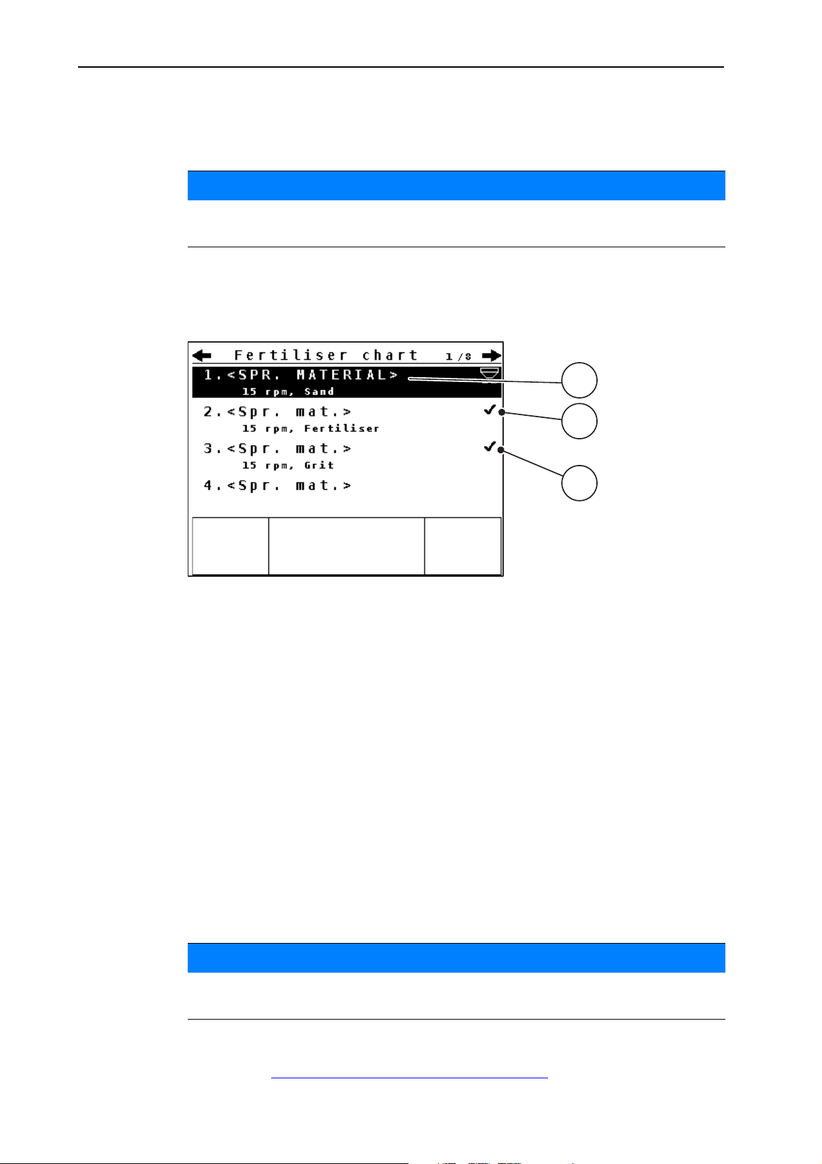
4.5.9 Fertiliser chart
In these menus, you can create and manage your own fertiliser charts.
The selection of a fertiliser chart affects the spreading material settings at the
control unit and the machine. The application rate setting remains unaffected.
Creating a new fertiliser chart
The control unit can store up to 30 fertiliser charts.
1. Open the Fertiliser/Spread. mat. settings > fertiliser chart menu.
NOTICE
Figure 4.9: Fertiliser chart menu
[1] Fertiliser chart name field
[2] Display of active fertiliser chart
[3] Display of the fertiliser chart filled with values
2. Select a name field of an empty chart.
3. Press the Enter key.
The selection window is displayed.
4. Select the Open and return... option.
5. Press the Enter key.
The Fertiliser/Spread. mat. settings menu is displayed and the selected
element is loaded as active fertiliser chart.
6. Select the Fertiliser name in the menu.
7. Press the Enter key.
8. Enter a name for the fertiliser chart.
NOTICE
We recommend naming the fertiliser chart with the spreading material name to
improve the allocation of the fertiliser chart to a spreading material.
38
9. Edit the parameters of the fertiliser chart.
Refer to 4.5:
Spreading material settings, page 29.
Page 45

Operation QUANTRON-A
Selecting a fertiliser chart:
1. Open the Fertiliser/spread. mat. settings > fertiliser chart menu.
2. Select the required fertiliser chart.
The name field consists of the name of the spreading material, the working
width, and the speed.
3. Press the Enter key.
The selection window is displayed.
4. Select the Open and return... option.
5. Press the Enter key.
The Fertiliser/Spread. mat. settings menu is displayed and the selected
element is loaded as active fertiliser chart.
Copying an existing fertiliser chart
1. Select the required fertiliser chart.
2. Press the Enter key.
The selection window is displayed.
4
3. Select the Copy element function.
4. Press the Enter key.
The fertiliser chart is copied to the first free position in the list.
Deleting an existing fertiliser chart
1. Select the required fertiliser chart.
2. Press the Enter key.
The selection window is displayed.
3. Select the Delete element function.
4. Press the Enter key.
The fertiliser chart was deleted.
39
Page 46
Operation QUANTRON-A 4
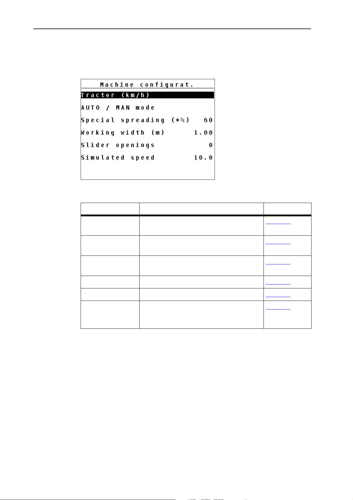
4.6 Machine configurat.
In this menu, the tractor and machine settings can be configured.
Open the Machine settings menu.
Figure 4.10: Machine configurat. menu
Sub-menu Meaning Description
Tractor (km/h) Determining or calibrating the speed sig-
Page 41
nal
AUTO/MAN mode Setting the automatic or manual operating
Page 44
mode.
Special spreading
(+%)
Presetting for special spreading
(Winter spreader UKS only)
Page 46
Working width Input of working width Page 47
Slider openings Number of closed metering sliders; Page 47
Simulated speed Pre-settings for spreading with simulated
Page 48
speed when starting at crossings or in the
headlands
40
Page 47
4.6.1 Forward speed calibration
1
2
4
5
3
The forward speed calibration is the basic requirement for an exact spreading result. Factors such as tyre size, a different tractor, all-wheel drive, slippage between tyres and ground, ground characteristics and tyre pressure influence the
speed measurement and therefore the spreading result.
Preparing the forward speed calibration:
The exact calculation of the number of speed pulses over 100 m is very important
for the precise discharge of the fertiliser quantity.
Conduct the calibration in the field. This reduces the influence of the ground
characteristics on the calibration result.
Determine a 100 m long reference track as precisely as possible.
Switch on four-wheel drive.
Fill only half of the machine, if possible.
Access the forward speed calibration:
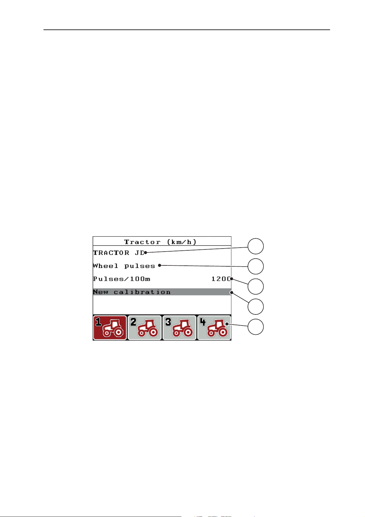
In the QUANTRON-A control unit, you can save up to 4 different profiles for the
type and number of pulses. You can assign names to these profiles (e.g. tractor
name).
Operation QUANTRON-A
4
Before spreading, check that the correct profile is opened in the control unit.
Figure 4.11: Tractor (km/h) menu
[1] Tractor type
[2] Transducer display for the speed signal
[3] Display of number of pulses over 100 m
[4] Tractor calibration sub-menu
[5] Icons for memory locations of profiles 1 to 4
1. Open the Machine configurat. > Tractor (km/h) menu.
The displayed values for name, origin and number of pulses refer to the profile highlighted in black.
2. Press the function key (F1-F4) under the memory location symbol.
41
Page 48
Operation QUANTRON-A 4
1
2
4
3
5
6
New calibration of the forward speed signal:
You can either overwrite an existing profile or create a profile in an empty memory
location.
1. Select the desired memory location in the Tractor (km/h) menu using the
function key below.
2. Select the New calibration field.
3. Press the Enter key.
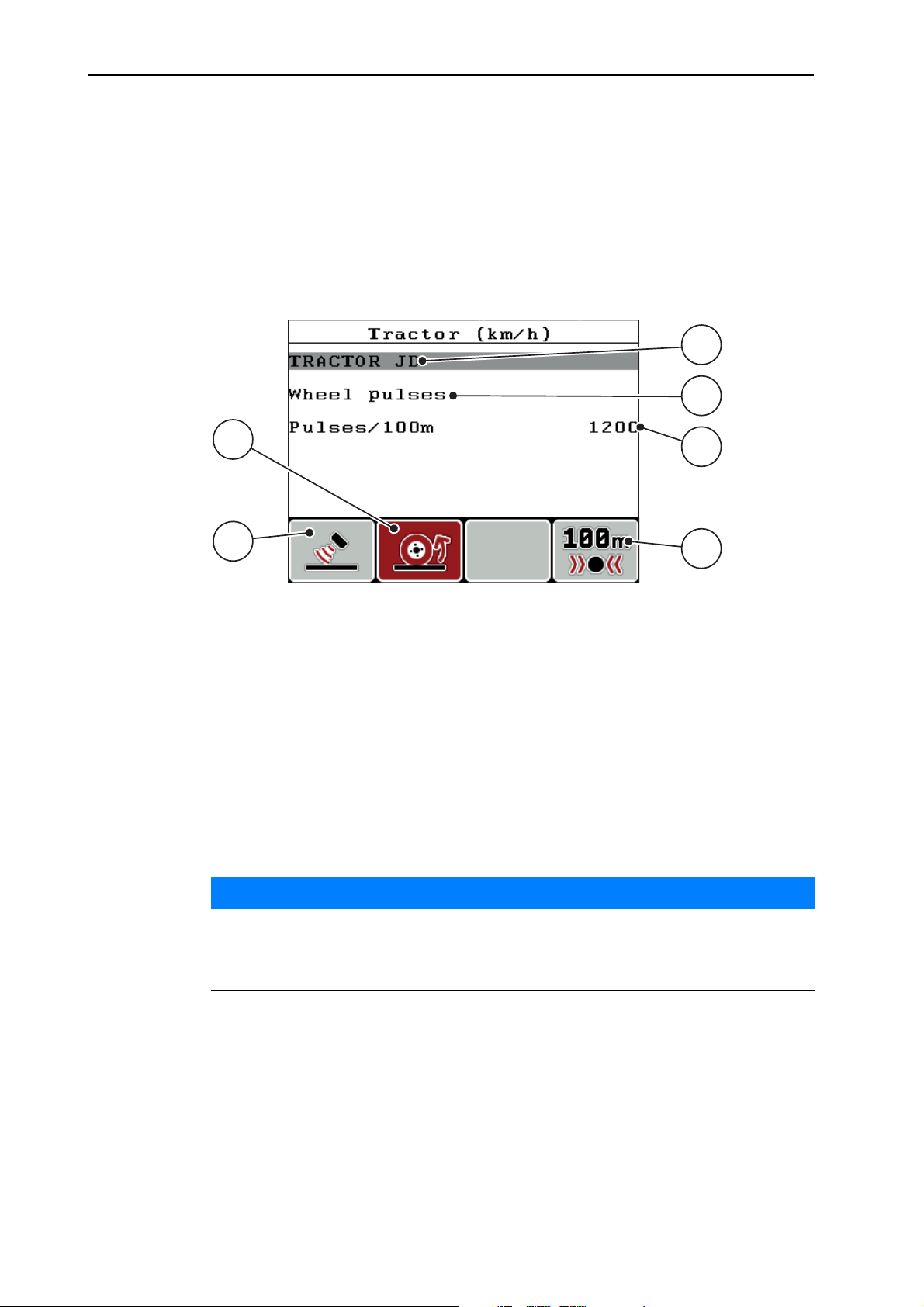
The Tractor (km/h) calibration menu is displayed.
Figure 4.12: Tractor (km/h) calibration menu
[1] Tractor name field
[2] Display of origin of speed signal
[3] Display of number of pulses over 100 m
[4] Automatic calibration sub-menu
[5] Radar pulse transducer
[6] Wheel pulse transducer
4. Highlight the Tractor name field.
5. Press the Enter key.
6. Enter the name of the profile.
NOTICE
The name entered is restricted to 16 characters.
We recommend using the profile with the name of the tractor for ease of understanding.
7. Select the pulse transducer for the forward speed signal.
For Radar pulses, press the F1 function key [5].
For Wheel pulses, press the F2 function key [6].
The pulse transducer is displayed.
42
Page 49
Operation QUANTRON-A
1
23
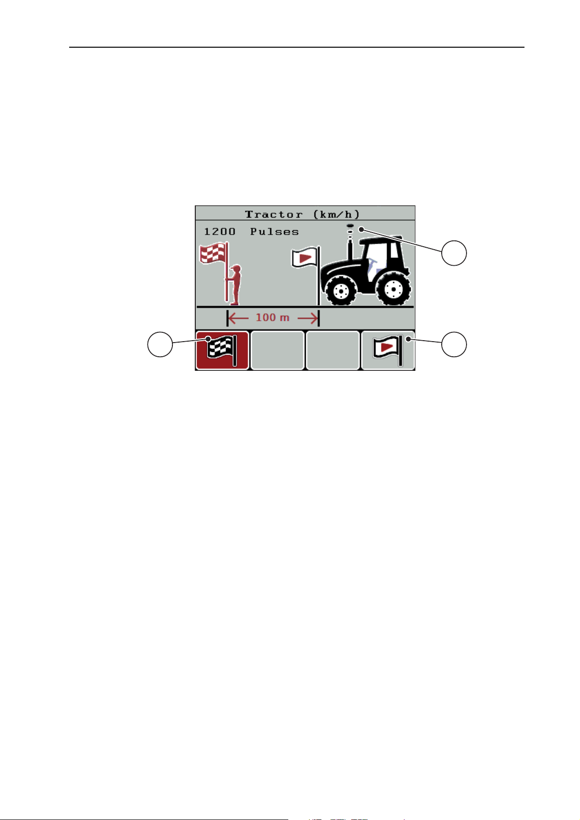
The number of pulses of the speed signal must still be specified below. If the exact number of pulses is known, it can be entered directly:
8. Open Tractor (km/h) > New calibration > Imp/100m in the menu.
The pulses menu for manual pulse count input is displayed.
If the exact pulse count is unknown, initialise a calibration run.
9. Press the F4 (100 m AUTO) function key.
The calibration run operating screen is displayed.
4
Figure 4.13: Calibration run speed signal operating screen
[1] Pulse display
[2] Start recording pulses
[3] Stop recording pulses
10. Press the F4 function key [2] at the starting point of the reference distance.
The pulse display is now on zero.
The control unit is ready for counting pulses.
11. Drive a reference distance of 100 m.
12. Stop tractor at the end of the reference distance.
13. Press the F1 function key [3].
The display shows the number of received pulses.
14. Press the Enter key.
The new pulse count is saved.
The calibration menu is displayed again.
43
Page 50
Operation QUANTRON-A 4
4.6.2 AUTO/MAN mode
By default, the AUTO km/h operating mode is selected. The control unit automatically controls the actuator based on the speed signal.
The manual mode is only applied in the following cases:
there is no speed signal (radar or wheel sensor not available or defective),
application of slug pellets or seeds (fine seeds).
For uniform spreading of the spreading material, a constant forward speed
has to be ensured in manual operating mode.
NOTICE
NOTICE
For spreading with different operating modes, refer to chapter 5:
Spreading op-
eration with the QUANTRON-A control unit, page 65.
Menu Meaning Description
AUTO km/h Selecting the automatic mode Page 45
MAN km/h Forward speed adjustment for manual mode Page 45
MAN scale Metering slide adjustment for manual mode Page 46
Selecting the operating mode
1. Switch on the control unit QUANTRON-A.
2. Open the Machine configurat. > AUTO/MAN mode menu.
3. Select the required menu item.
4. Press the Enter key.
For important information on the use of the operating modes for spreading op-
eration refer to chapter 5.2:
Spreading in the AUTO km/h operating mode,
page 66.
44
Page 51

Operation QUANTRON-A
AUTO km/h: Automatic operation
NOTICE
In order to achieve an optimum spreading result, a calibration test should be carried out before spreading.
1. Switch on the control unit QUANTRON-A.
2. Open the Machine configurat. > AUTO/MAN mode menu.
3. Select AUTO km/h in the menu.
4. Press the Enter key.
5. Configure the fertiliser settings:
Application rate (kg/ha)
Working width (m)
6. Fill the hopper with spreading material.
7. Carry out calibration test to determine the flow factor
4
or
determine the flow factor using the provided fertiliser chart.
8. Enter the flow factor manually.
9. Press the Start/Stop key.
The spreading starts.
NOTICE
In order to achieve an optimum spreading result, a calibration test should be
carried out before spreading.
MAN km/h: manual operation
1. Switch on the control unit QUANTRON-A.
2. Open the Machine configurat. > AUTO/MAN mode menu.
3. Select MAN km/h in the menu.
The Forward speed input window is displayed.
4. Enter the forward speed during spreading.
5. Press the Enter key.
NOTICE
In order to achieve an optimum spreading result, a calibration test should be carried out before spreading.
45
Page 52

Operation QUANTRON-A 4
MAN scale: manual operation with scale value
1. Open the Machine configurat. > AUTO/MAN mode menu.
2. Select MAN scale in the menu.
The display shows the metering slide opening menu.
3. Enter the scale value for the metering slide opening.
4. Press the Enter key.
The operating mode setting is saved.
NOTICE
In order to achieve an optimum spreading result in manual mode as well, we recommend using the values for metering slide opening and forward speed provided in the fertiliser chart.
4.6.3 Special spreading (+%; winter spreader UKS only)
In the Special spreading (+%) menu, an Application rate adjustment percentage can be specified for normal spreading.
The basis is the pre-set value of the spreading density. 100% special spreading
density correspond to a doubling of the spreading density set.
NOTICE
During operation, the spreading rate can be adjusted at any time by pressing
the T key (special spreading).
See 2.4: Control elements, page 7
The application rate can only be increases, and not decreases.
Adjusting the application rate:
1. Open the Machine configurat. > special spreading (+%) menu.
2. Enter the percentage value by which you wish to increase the application
rate.
3. Press the Enter key.
Special spreading:
1. From the Machine configurat. menu, change to the operating screen.
2. To activate spreading of the pre-set additional quantity during the spreading
operation press and hold the T key (see 2.4:
Control elements, page 7).
46
NOTICE
The additional quantity is only spread while the T key is held.
Page 53

4.6.4 Working width
The working width is factory set to the machine type with which the control unit is
delivered. For mounting special equipment a smaller or greater working width
may be required.
The pre-set working width (in metres) can be adjusted in this menu.
Entering the working width:
1. Open the Machine configurat. > Working width menu.
The working width set on the basis of the programmed machine is dis-
2. Enter the new value.
3. Press the Enter key.
The new value is saved in the control unit.
played.
NOTICE
Operation QUANTRON-A
4
Depending on the mounted special equipment and the application, the decrease of the working width is achieved in combination with closed metering
slide openings.
Enter the new working width and the number of closed metering slide open-
ings in the machine configurat. menu.
4.6.5 Metering openings
In this menu, the number of closed metering openings is entered.
1. Open the Machine configurat. > Slider openings menu.
2. Enter the number of closed metering openings.
- 0 is pre-set: All slide openings are open.
- A maximum of 10 slide openings can be closed.
The control unit adjusts the opening position of the metering slide. This
ensures that the spreading density in g/m² is maintained.
3. Press the Enter key.
The new value is saved in the control unit.
47
Page 54
Operation QUANTRON-A 4
1
2
4.6.6 Simulated speed
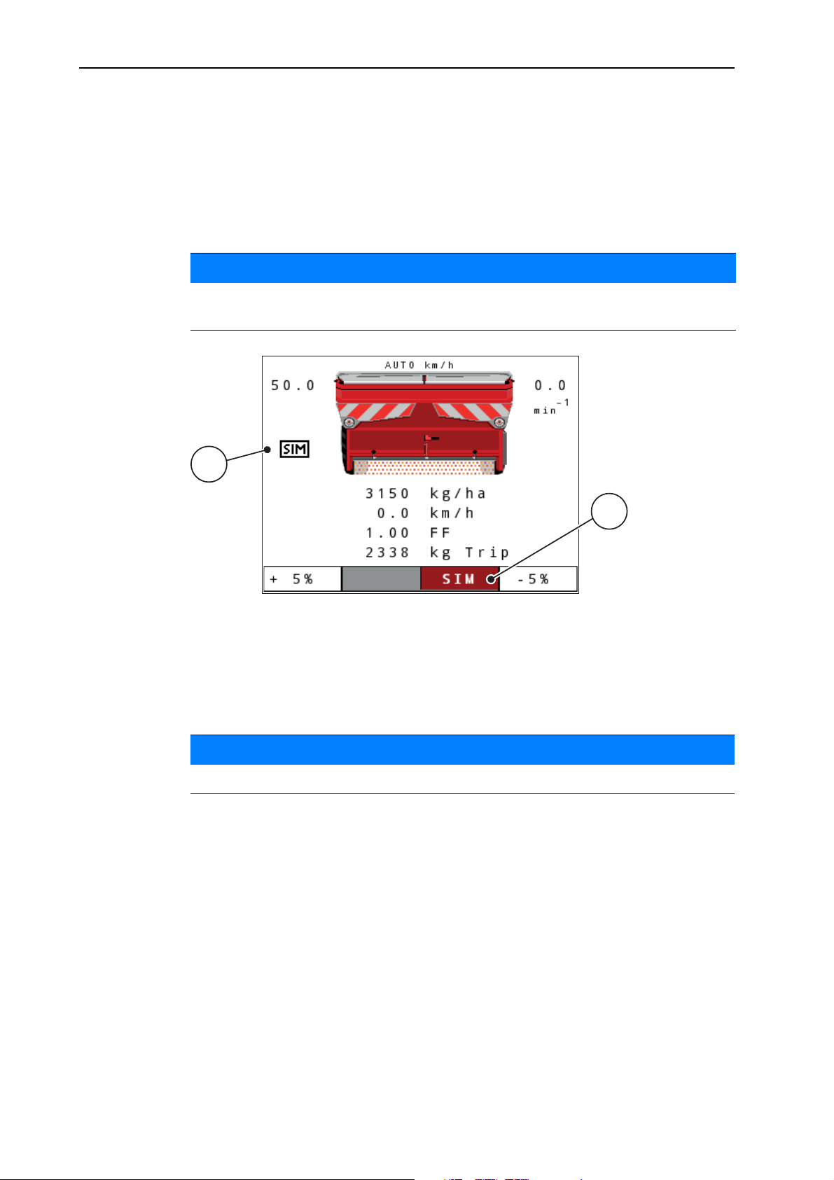
In the simulated speed menu, a simulated speed can be specified for normal
spreading.
The simulated speed should be activated when starting at crossings, traffic lights
or in the headlands. With the simulated speed function, the metering slide opens
immediately and the spreading starts with the first meter.
The simulated speed function can only be activated when the tractor is at a
standstill.
NOTICE
Figure 4.14: Simulated speed
[1] Symbol for simulated speed
[2] The simulated speed is activated.
Defining the simulated speed:
NOTICE
The factory setting for the simulated speed is 0.0 km/h!
1. Open the Machine configurat. > Simulated speed menu.
2. Enter the speed to be simulated.
3. Press the Enter key.
48
Page 55
Operation QUANTRON-A
Spreading with simulated speed:
Requirements
The operating screen is displayed.
a) Automatic simulation is not activated; display field is highlighted in grey.
1. Press the Start/Stop key.
The spreading operation is activated.
4
2. Press the T key with the machine at a standstill (see figure 2.2
).
The simulated speed is activated.
The metering slide opens.
b) Activating the automatic simulation.
1. Press the F3 function key.
The display field is highlighted in red.
2. Press the T key with the machine at a standstill (see ).
The spreading operation is activated.
The simulated speed switches on automatically.
The metering slide opens.
If the spreading operation is interrupted, the simulated speed is deactivated.
3. When restarting the spreading operation, press the T key.
The automatic, simulated speed is active again.
NOTICE
The simulated speed remains active until it is exceeded by the actual speed. After having exceeded the simulated speed, the metering quantity is calculated
based on the actual speed.
NOTICE
The simulated speed can be deactivated by pressing the T key again.
49
Page 56

Operation QUANTRON-A 4
4.7 Fast emptying
In order to quickly clean the machine after the spreading work or to quickly empty
any residual material, the Fast emptying menu can be selected.
Before storing the machine, we recommend to completely open the metering
slide via the fast emptying function and to switch off the QUANTRON-A in this
state. This prevents accumulation of humidity in the hopper.
Before starting the fast emptying process, ensure that all requirements have
been met. Please refer to the operator's manual of the machine (emptying of residual material).
1. Open the Main menu > Fast emptying menu.
2. Press the Start/Stop key.
The fast emptying process starts.
3. Press the Start/Stop key again.
NOTICE
The fast emptying process is stopped.
50
Page 57
4.8 File/field data
Delete
all
Delete
9
8
7
6
5
1
2
3
4
File
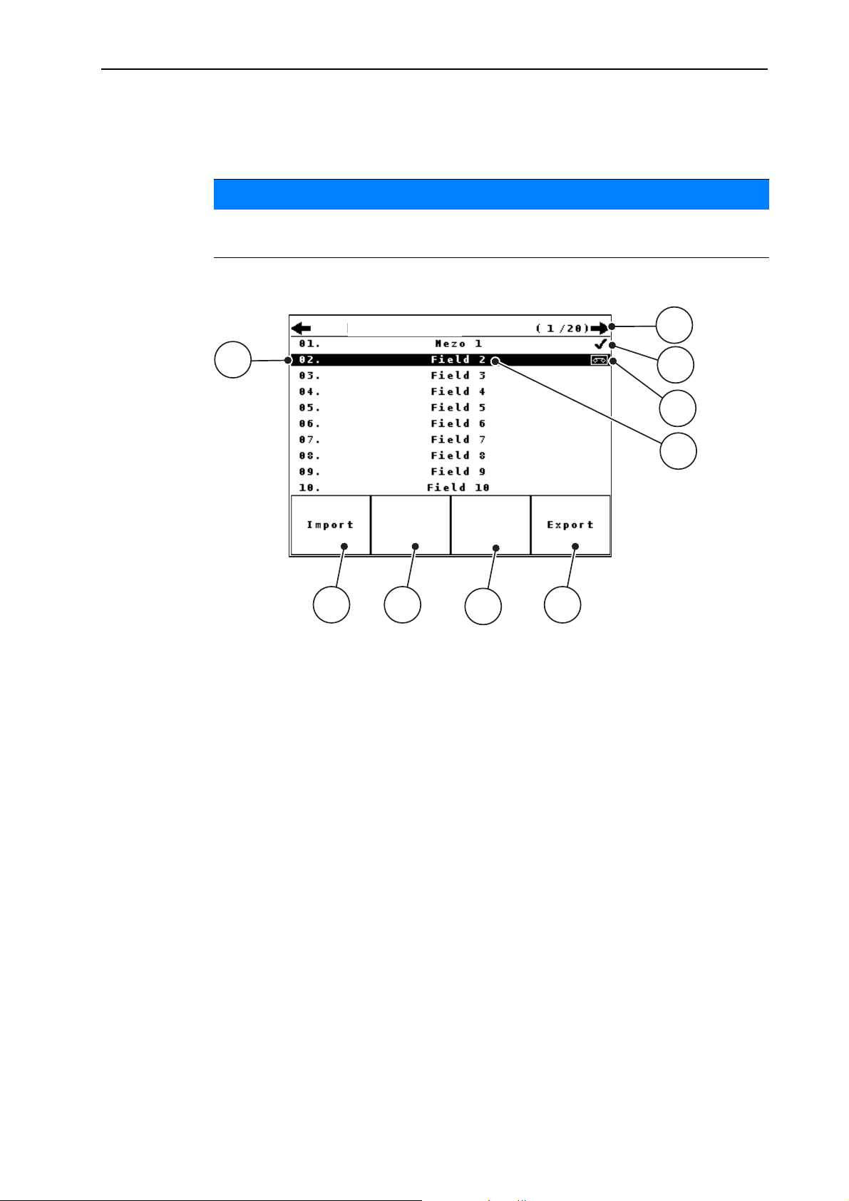
In this menu, you can create and manage up to 200 files/field data files.
For reasons of understanding the term File is used for both, field data (fertiliser
spreaders UKS GB and LINUS) and for file (winter spreader UKS).
Open the Main menu > File menu.
NOTICE
Operation QUANTRON-A
4
Figure 4.15: File menu
[1] Display of page number
[2] Display of filled file
[3] Display of active file
[4] File name
[5] Function key Export
[6] Function key Delete file
[7] Function key Delete all files
[8] Function key Import
[9] Display of disc space
51
Page 58

Operation QUANTRON-A 4
4.8.1 Selecting a file
Already saved files can be selected and processed. The data already saved in
the file is not overwritten, but the new values are added.
With the left/right arrow keys you can jump forward and back through the pages in the file menu.
1. Select the required file.
2. Press the Enter key.
The first page of the current file is displayed.
NOTICE
52
Page 59
4.8.2 Starting the recording
Operation QUANTRON-A
1
2
3
4
3
4
5
9
6
8
7
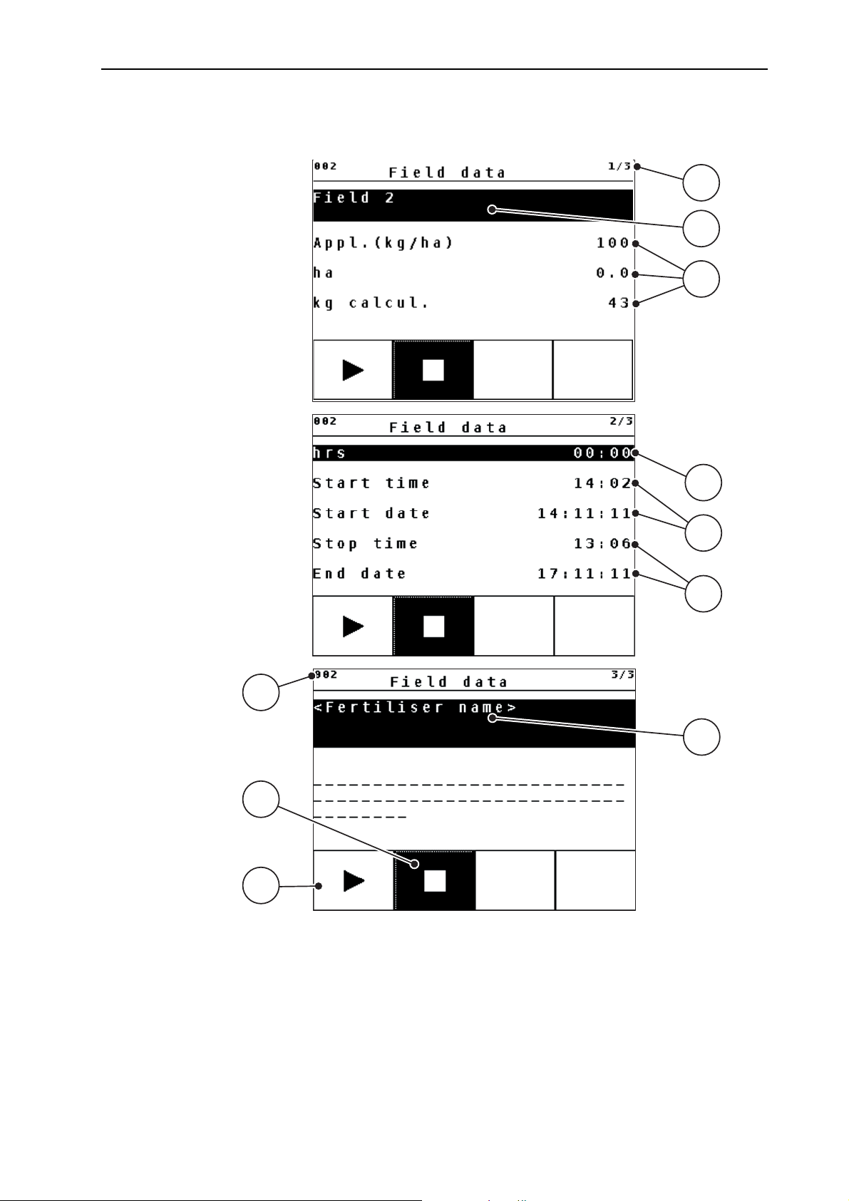
Figure 4.16: Display of current file
[1] Display of the page number
[2] Name field of field data/file
[3] Value fields
[4] Display of the start time/date
[5] Display of the stop time/date
[6] Name field of fertiliser
[7] Function key Start
[8] Function key Stop
[9] Display of disc space
53
Page 60
Operation QUANTRON-A 4
1
3. Press the F1 function key [7].
The recording starts.
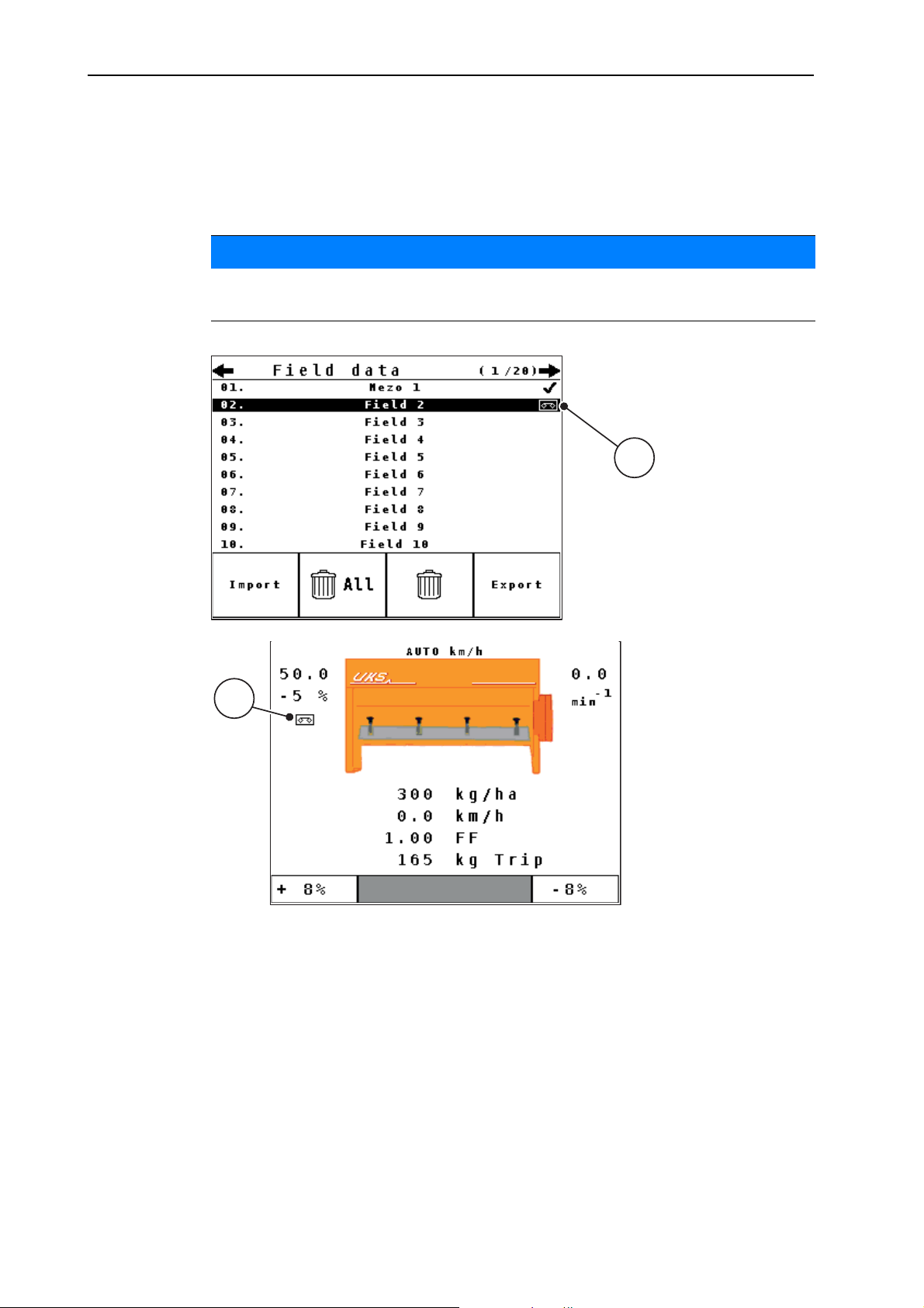
The File menu displays the recording symbol for the current file.
The operating screen displays the recording symbol.
NOTICE
If another file is opened, this file will be stopped. The active file cannot be deleted.
1
Figure 4.17: Recording symbol display
[1] Recording symbol
4.8.3 Stopping the recording
1. Open the first page of the active file in the File menu.
2. Press the F2 function key below the stop symbol.
The recording is stopped.
54
Page 61

4.8.4 Importing and exporting files
The control unit QUANTRON-A allows the import and/or export of the recorded
field data/files.
Importing files (PC to QUANTRON-A)
Requirements:
Use the USB stick supplied.
Do not alter the directory structure on the USB stick.
The data on the USB stick are stored in the directory \\USB-BOX\Quantro-
nA\(Dateien\Import.
1. Open the File menu.
Operation QUANTRON-A
4
2. Press the F1 Import function key (see figure 4.15
).
Error message no. 7 appears indicating that the current files will be over-
written. See 6.1:
Meaning of the alarm messages, page 69
3. Press the Start/Stop key.
The bar shows the progress of the transfer.
NOTICE
You can interrupt the import of field data at any time by pressing the ESC key!
The consequences of importing field data/files are as follows
All files currently stored in the QUANTRON-A are overwritten.
If you have defined the application rate on the PC, the application rate is au-
tomatically transferred and immediately activated in the Fertiliser settings
when starting the file.
If you enter an application rate outside the range of 10-3000, the value in the
Fertiliser settings menu is not overwritten.
Exporting field data/files (QUANTRON-A to PC)
Requirements:
Use the USB stick supplied.
Do not alter the directory structure on the USB stick.
The data on the USB stick are stored in the directory \\USB-BOX\Quantro-
nA\Dateien\Export.
1. Open the File menu.
2. Press the F4 Export function key (see figure 4.15
).
The bar shows the progress of the transfer.
55
Page 62
Operation QUANTRON-A 4
4.9 System/test
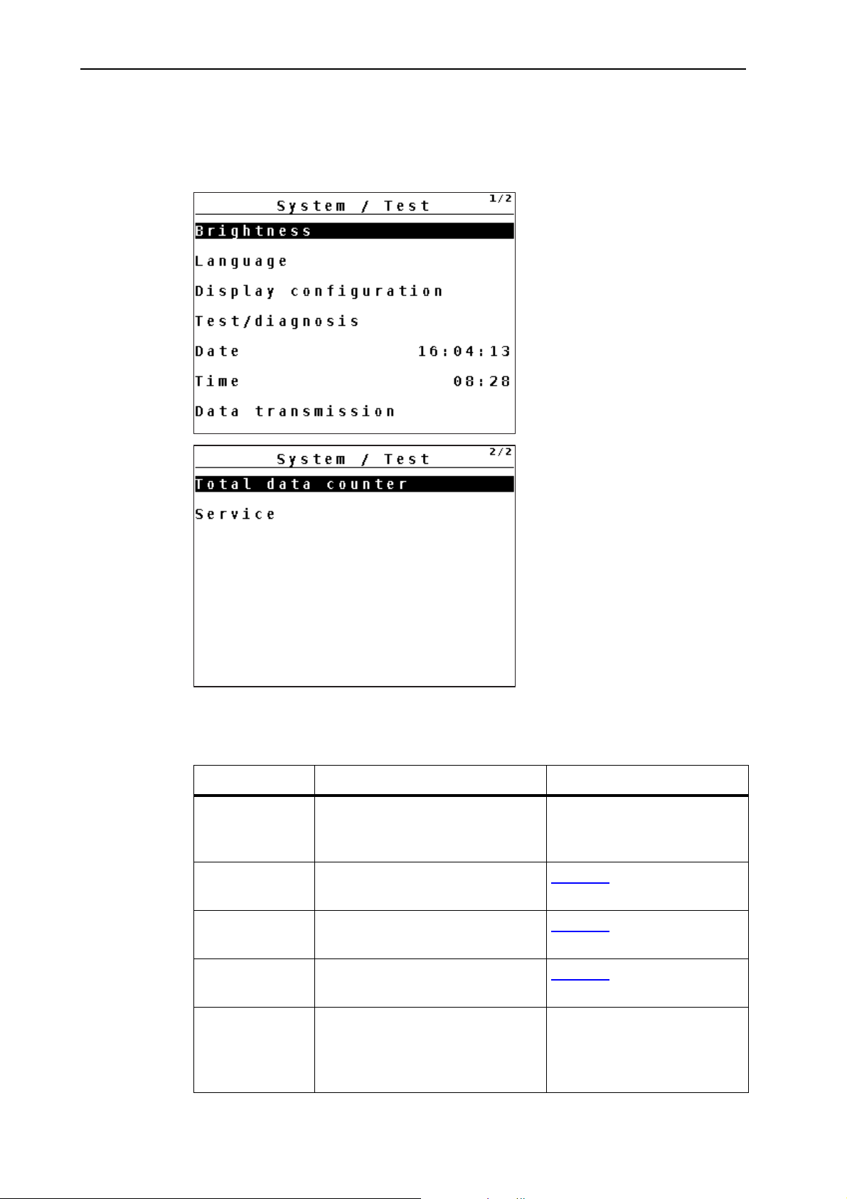
Use this menu for the system and test settings of the control unit.
Open the Main menu > System/test menu.
Figure 4.18: System/test menu
Sub-menu Meaning Description
Brightness Display settings The settings can be adjust-
ed with the function keys +
or -.
Language Language setting for menu navi-
Page 57
gation.
Display configuration
Test/diagnosis Checking of actuators and sen-
Determining the displays on the
operating screen.
Page 58
Page 59
sors.
Date Setting the current date. Selection and modification
of the settings by means of
the Arrow keys; confirmation using the Enter key
56
Page 63

Operation QUANTRON-A
Sub-menu Meaning Description
Time Setting the current time. Selection and modification
of the settings by means of
the Arrow keys; confirmation using the Enter key
4
Data transmission
Total data counter
Service Service settings Password-protected; only
4.9.1 Setting the language
In the QUANTRON-A control unit, several languages can be set.
The language package for your country is pre-set at the factory.
Should you miss a language, please contact your dealer.
Menu for data exchange and serial protocols
Display of total
spread quantity in kg
spread area in ha
spread time in h
distance travelled in km
NOTICE
Page 61
accessible to service personnel
1. Open the System/test > Language menu.
The first of two pages is displayed.
2. Select the language to be used for the menus.
3. Press the Enter key.
The selection is confirmed.
The QUANTRON-A control unit restarts automatically.
The menus are displayed in the selected language.
57
Page 64
Operation QUANTRON-A 4
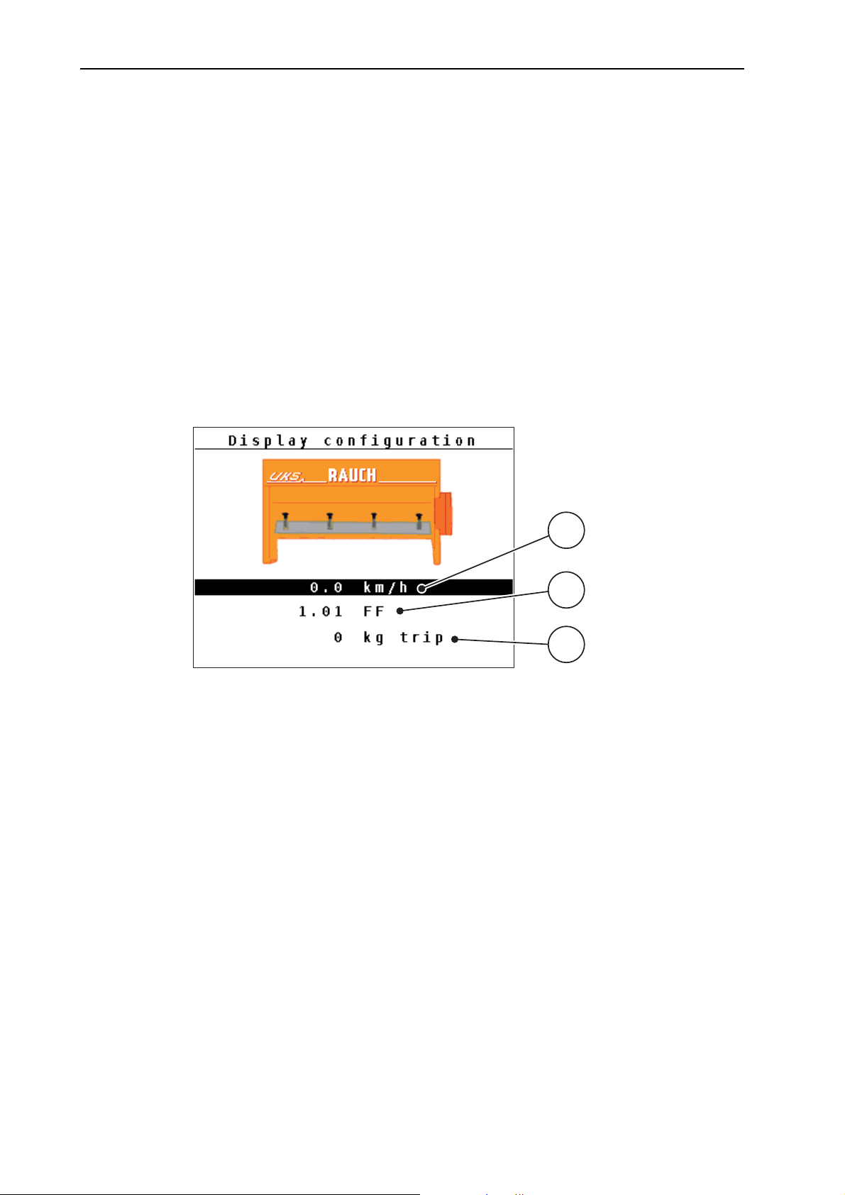
4.9.2 Display configuration
The display fields in the operating screen of the control unit can be configured as
desired. You can assign the three display fields with the following values if desired:
Forward speed
Flow factor (FF)
Time
ha trip
kg trip
m trip
kg rest
km Rest
ha rest
1
2
3
Figure 4.19: Display configuration menu
[1] Display field 1
[2] Display field 2
[3] Display field 3
Select display
1. Open the System/test > Display configuration menu.
2. Select the required display field.
3. Press the Enter key.
The available options are displayed in a list.
4. Select the new value to be assigned to the display field.
5. Press the Enter key.
58
The operating screen is shown on the display. The respective display
field displays the new value.
Page 65
4.9.3 Test/diagnosis
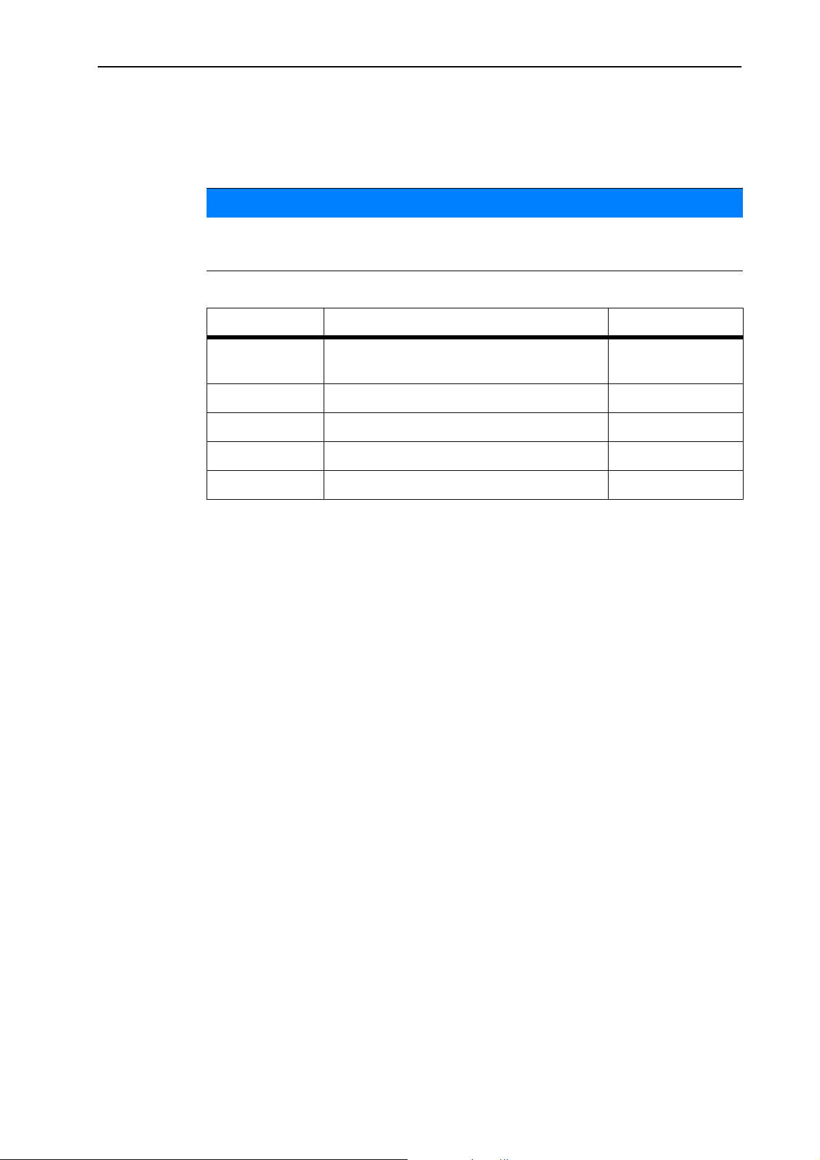
The Test/diagnosis menu enables function monitoring of specific sensors/actuators.
This menu is for information purposes only.
The list of sensors depends on the equipment of the machine.
Sub-menu Meaning Description
NOTICE
Operation QUANTRON-A
4
Dosing slider
test points
Test for approaching the various position
points of the metering slide.
Metering slide Manual actuation of the metering slide
Speed sensor Checking the agitator shaft speed
Voltage Checking the operating voltage.
Level sensor Checking the level sensor
Checking the calibration
59
Page 66
Operation QUANTRON-A 4
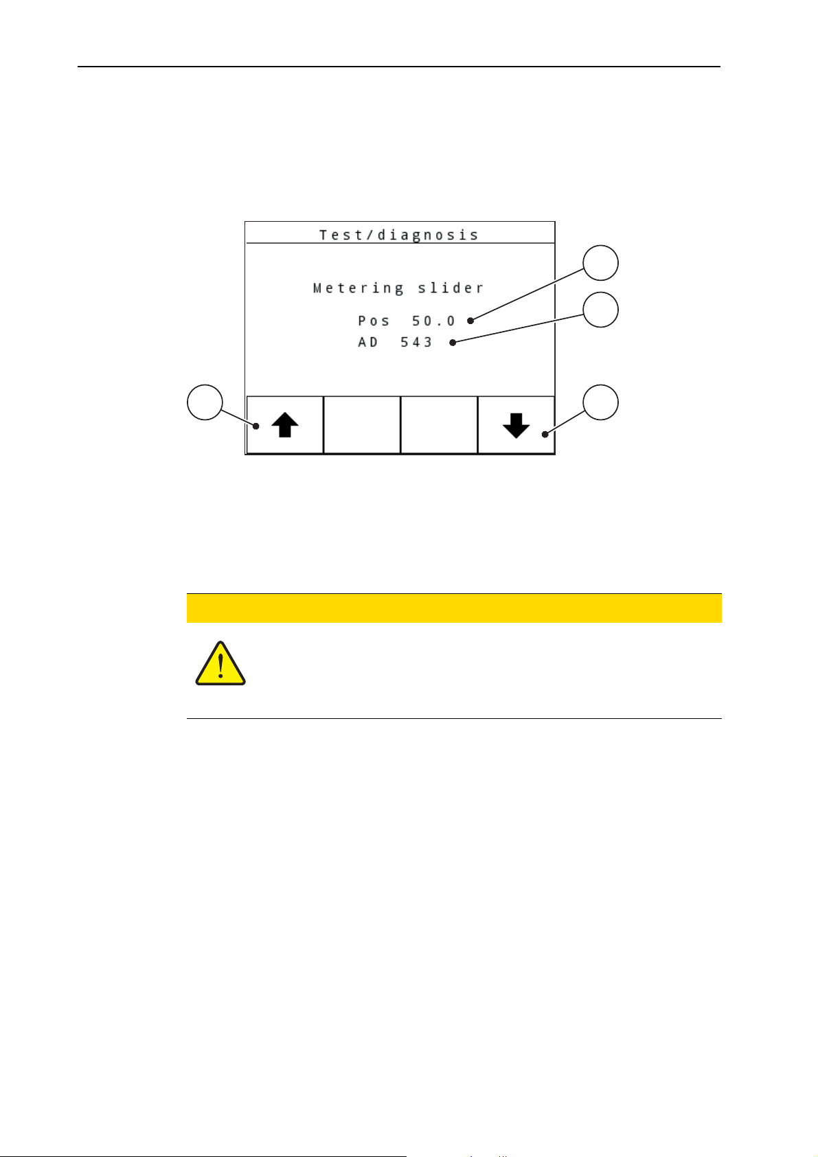
1
4
3
2
Slide example
1. Open the System/test > Test/diagnosis menu.
2. Select the metering slide in the menu.
3. Press the Enter key.
The actuator/sensor status is displayed.
Figure 4.20: Test/diagnosis; example: Slide
[1] Position display
[2] Signal display
[3] Function keys for right actuator
[4] Function keys for left actuator
n CAUTION
Risk of injury due to moving machine parts.
During the tests, machine parts may start to move automatically.
Before carrying out the test, ensure that nobody is present
in the danger zone of the machine.
The status of the signal for the left and right hand side is displayed separately by
means of the signal display.
The actuators can be extended and retracted by pressing the F1 - F4 function
keys.
60
Page 67
4.9.4 Data transmission
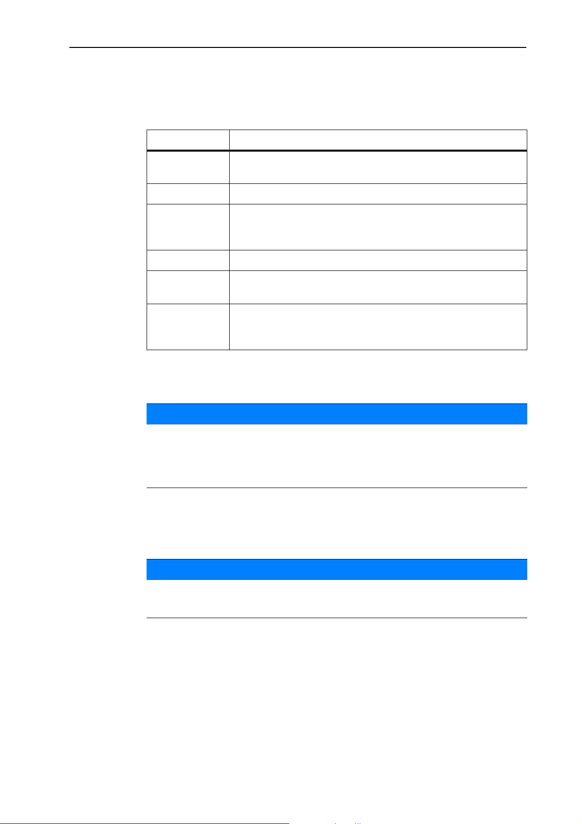
Data transmission is carried out using various data protocols.
Sub-menu Meaning
ASD Automatic field documentation; transmission of field data to a
LH5000 Serial communication e.g. spreading using application cards
TUVR Protocol for automatic section control, area-specific quantity
GPS km/h Protocol for GPS speed with external Trimble Terminal.
GPS Control Protocol for the automatic section control with an external ter-
Operation QUANTRON-A
PDA and/or Pocket PC via Bluetooth
changes and GPS speed by means of an external Trimble Terminal.
minal
4
4.9.5 Service
4.10 Info
VRA GPS control
VRA Variable Rate Application
Protocol for the automatic transmission of the target application rate and the automatic section control
NOTICE
An input code is required to adjust the settings in the Service menu. These settings can only be modified by authorised service personnel.
As a general rule, we recommend that all settings in this menu are carried out
by authorized service personnel.
Information on the machine control can be obtained from the Info menu.
NOTICE
This menu provides information on the configuration of the machine.
The information list depends on the equipment of the machine.
61
Page 68
Operation QUANTRON-A 4
4.11 Special functions
4.11.1 Text input
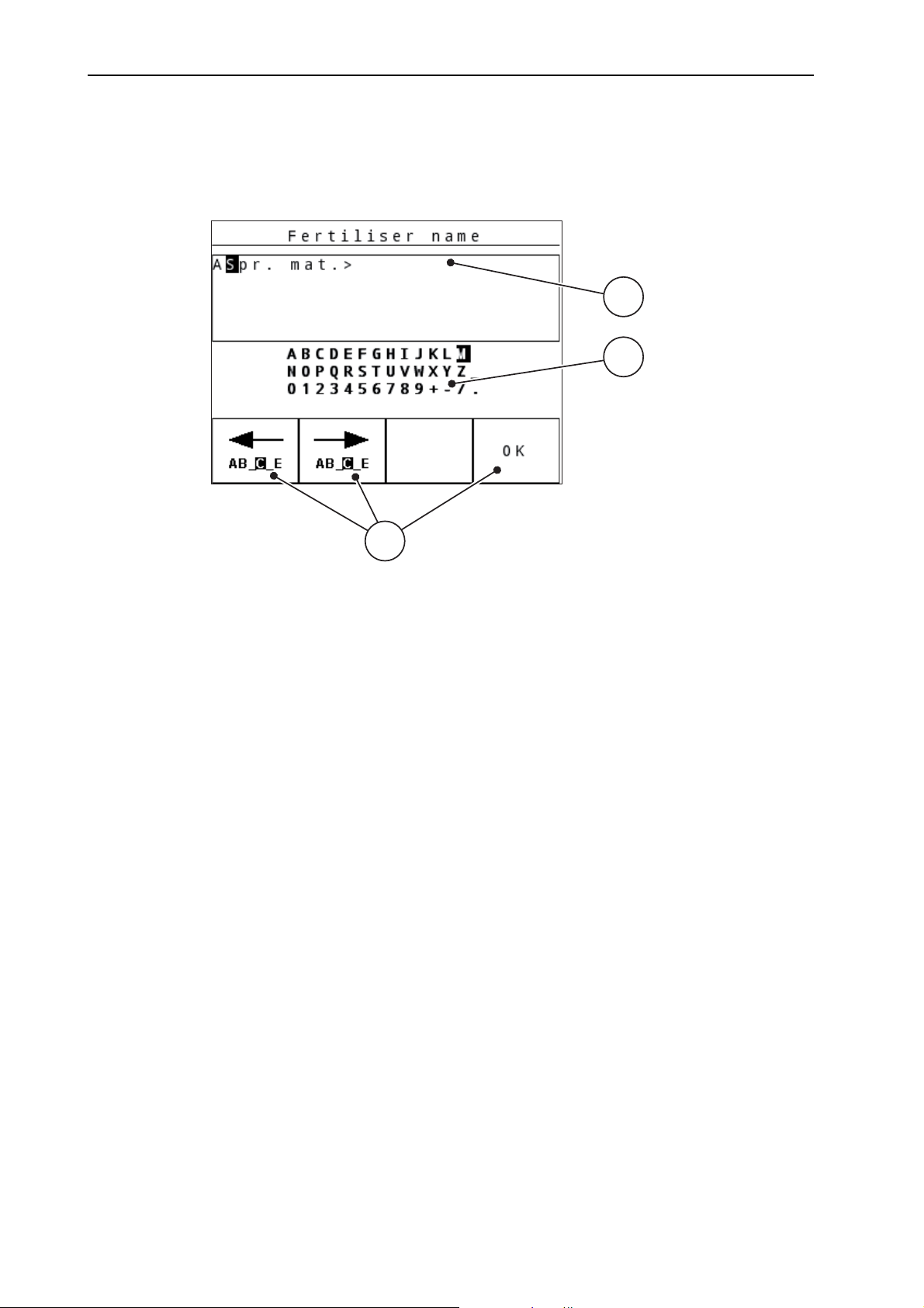
In some menus, freely editable text can be entered.
1
2
3
Figure 4.21: Text input menu (example)
[1] Input field
[2] Character field, display of available characters (language-dependent)
[3] Function keys for navigation in the input field
Entering text:
1. Switch from the superordinate menu to the Text input menu.
2. Use the function keys to move the cursor to the position of the character to
be written first in the input field.
3. Use the arrow keys to highlight the character to be written in the character
field.
4. Press the Enter key.
The highlighted character appears in the input field.
The cursor jumps to the next position.
Continue until you have entered the entire text.
5. Press the OK function key.
The control unit saves the text.
62
The previous menu is displayed.
Page 69

Operation QUANTRON-A
Overwriting characters:
A single character can be overwritten by another character.
1. Use the function keys to move the cursor to the position of the character to
be deleted first in the input field.
2. Use the arrow keys to select the character to be written in the character field.
3. Press the Enter key.
The character is overwritten.
4. To confirm the input, press the OK function key.
The text will be saved to the control unit.
The previous menu is displayed.
NOTICE
Individual characters can only be deleted by replacing them with blank spaces
(underline at the end of the first 2 character lines).
4
Deleting an input:
The complete input can be deleted.
1. Press the C 100 % key.
The complete input is deleted.
2. Enter new text, if necessary.
3. Press the OK function key.
63
Page 70
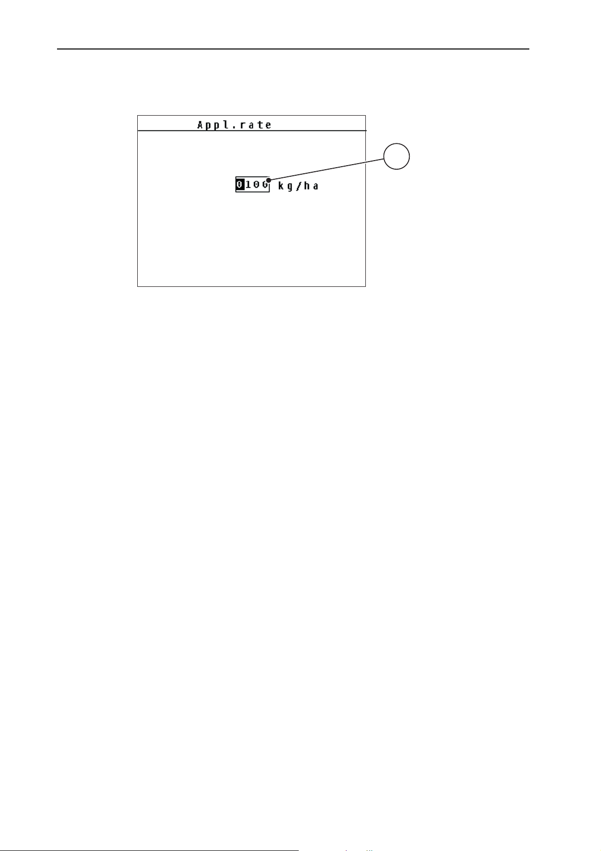
Operation QUANTRON-A 4
4.11.2 Entering values with the cursor keys
In some menus, numerical values can be entered.
Figure 4.22: Input of numerical value (example application rate)
[1] Input field
1
Requirements:
You are already in the menu in which you can enter numerical values.
1. Use the horizontal arrow keys to move the cursor to the position of the numerical value to be written first in the input field.
2. Use the vertical arrow keys to enter the required numerical value.
Arrow up: Value increases.
Arrow down: Value decreases.
Arrow left/right: Cursor moves to the left/right.
3. Press the Enter key.
Deleting an input:
The complete input can be deleted.
1. Press the C 100 % key.
The complete input is deleted.
64
Page 71

Spreading operation with the QUANTRON-A control unit
5 Spreading operation with the QUANTRON-A control unit
The QUANTRON-A control unit supports you with the setting of your machine before you start your work. During spreading, functions of the control unit are also
active in the background. This allows you to monitor the quality of the fertiliser
spreading.
5.1 Calling up the residual material during spreading
During spreading, the residual material is continuously recalculated and displayed.
During spreading, i.e. with the metering slides open, change to the Rest (kg, ha,
m) menu to display the residual material currently in the hopper.
NOTICE
If the values are to be permanently monitored during spreading, freely assignable display fields in the operating screen can also be assigned with the kg rest,
ha rest or m rest values, refer to chapter 4.9.2: Display configuration, page 58
5
.
65
Page 72

Spreading operation with the QUANTRON-A control unit 5
5.2 Spreading in the AUTO km/h operating mode
1. Switch on the control unit QUANTRON-A.
2. Open the Machine configurat. > AUTO/MAN mode menu.
3. Select AUTO km/h in the menu.
4. Configure the fertiliser and/or spreading material settings:
Application rate (kg/ha or g/m²)
Agitator shaft speed
5. Fill in the spreading material.
NOTICE
In order to achieve an optimum spreading result in the AUTO km/h operating
mode, a calibration is to be carried out before starting the spreading work.
6. Conduct a calibration for flow factor determination
or
Obtain the flow factor from the fertiliser chart.
7. Enter the flow factor manually.
8. Press the Start/Stop key.
The spreading starts.
66
Page 73

Spreading operation with the QUANTRON-A control unit
5.3 Spreading in the MAN km/h operating mode
If there is no speed signal, the MAN km/h operating mode is active.
1. Switch on the control unit QUANTRON-A.
2. Open the Machine configurat. > AUTO/MAN mode menu.
3. Select MAN km/h in the menu.
4. Enter the forward speed.
5. Press OK.
6. Configure the fertiliser settings:
Application rate (kg/ha or g/m²)
Agitator shaft speed
7. Fill in the spreading material.
NOTICE
In order to achieve an optimum spreading result in the MAN km/h operating
mode, a calibration test is to be carried out before starting the spreading.
5
8. Carry out calibration test to determine the flow factor
or
Obtain the flow factor from the fertiliser chart and manually enter the flow factor.
9. Press the Start/Stop key.
The spreading starts.
NOTICE
Always observe the set speed during spreading.
67
Page 74
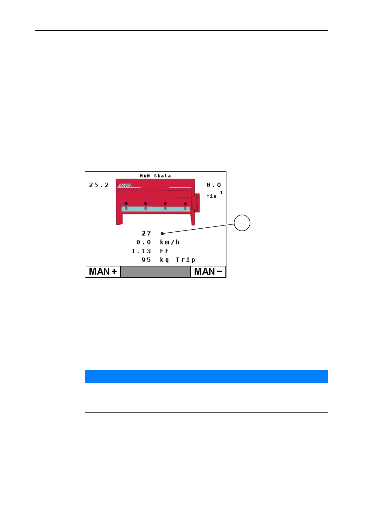
Spreading operation with the QUANTRON-A control unit 5
1
5.4 Spreading in the MAN scale operating mode
The MAN scale operating mode enables manual adjustment of the metering slide
opening during spreading.
1. Switch on the control unit QUANTRON-A.
2. Open the Machine configurat. > AUTO/MAN mode menu.
3. Select MAN scale in the menu.
4. Enter the position of the metering slide.
5. Press the Enter key.
6. Switch to the operating screen.
7. Press the Start/Stop key.
The spreading starts.
Figure 5.1: MAN scale operating screen
[1] Display of the current scale position of the metering slide
8. To change the metering slide opening, press the F1 or F4 function key.
F1: MAN+ to increase the metering slide opening or
F4: MAN- to reduce the metering slide opening.
With the C/100 % key, the previous settings are restored.
NOTICE
In order to achieve an optimum spreading result in manual mode as well, it is
recommended to apply the metering slide opening and forward speed values
provided in the fertiliser chart.
68
Page 75

Alarm messages and possible causes
6 Alarm messages and possible causes
Various alarm messages can be displayed on the QUANTRON-A control unit display.
6.1 Meaning of the alarm messages
Message in display Meaning
Possible cause
Fault in dosing system. Stop! The metering system actuator cannot reach the
target value.
Blockage
No position feedback
6
Maximum outlet reached! Speed or application rate too high
Metering slide alarm
The maximum metering opening is reached.
The set application rate (+/- appl. rate) ex-
ceeds the maximum metering opening.
Flow factor exceeds acceptable limits. The newly calculated or entered flow factor is
outside the valid range.
The flow factor must lie within one of the following
ranges (depending on the agitator shaft speed)
between 0.4 to 2.5 with an agitator shaft
speed of 15 rpm
between 0.4 to 3.5 with an agitator shaft
speed of 28 rpm
Hopper empty! The level sensor reports "empty".
The hopper is empty.
Data will be deleted!
Delete = START
Safety alarm to prevent the unintentional deletion
of data.
Cancel = ESC
Spreading density
Min. settting = 5
Max. settting = 40
Spreading density for dewing spreading material outside of the valid range.
The set value exceeds the reference values.
Only for
g/m²
Spreading density
Min. settting = 75
Max.settting = 300
Spreading density
Min. settting = 1
Max.settting = 300
Spreading density for blunting spreading material outside of the valid range.
The set value exceeds the reference values.
Spreading density for fertiliser outside of the
valid range.
The set value exceeds the reference values.
69
Page 76
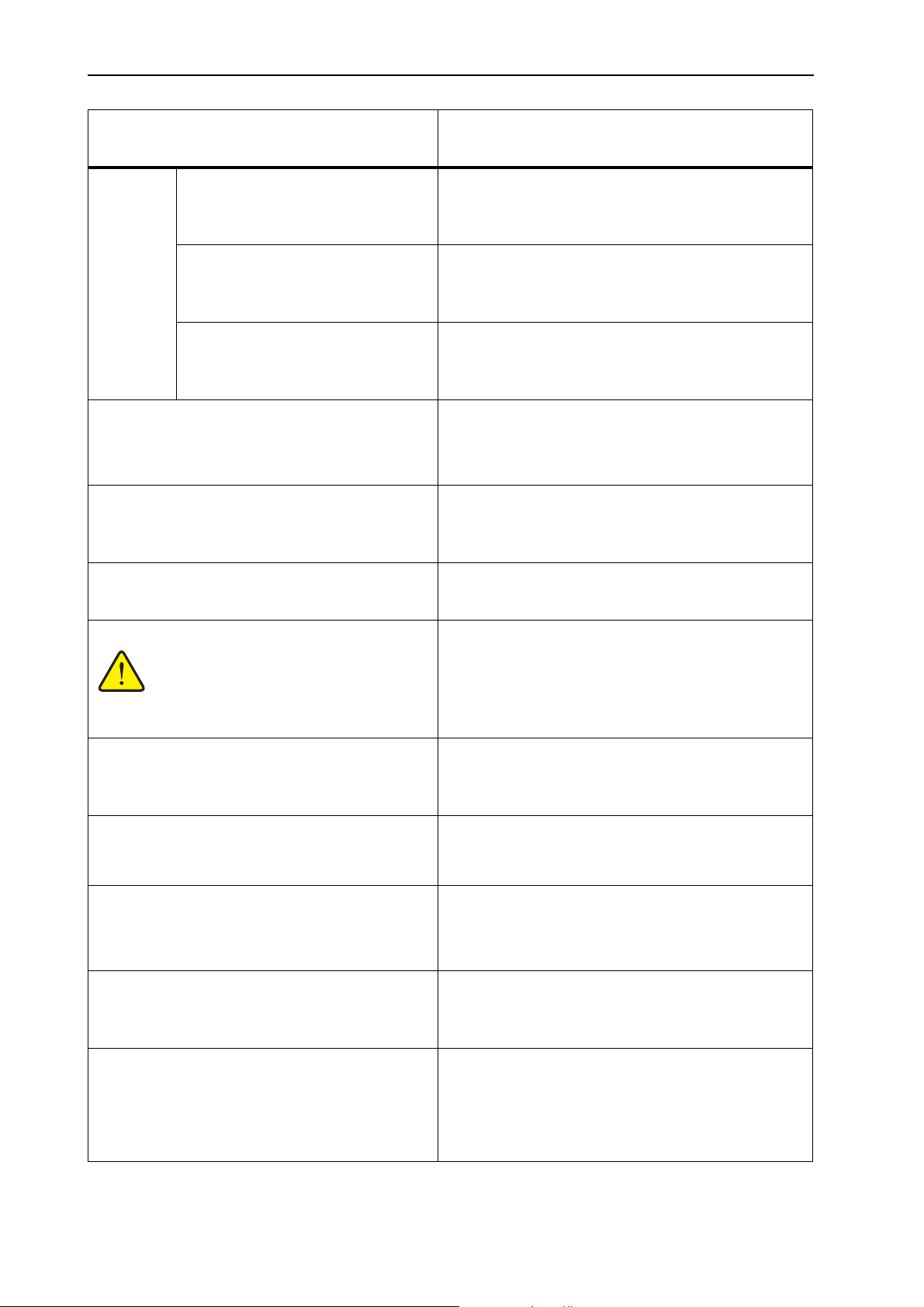
Alarm messages and possible causes 6
Message in display Meaning
Possible cause
Only for
Min. setting = 50
Max. setting = 400
Min. setting = 750
Max. setting = 3000
Application rate for dewing spreading material
outside of the valid range.
The set value exceeds the reference values.
Application rate for blunting spreading material
outside of the valid range.
kg/ha
The set value exceeds the reference values.
Min. setting = 1
Max. setting = 3000
Min. setting = xx
Max. setting = xx
Application rate for fertiliser outside of the valid
range.
The set value exceeds the reference values.
Reference to the value range of the flow factor.
Entered value is not permitted.
Range depends on the agitator shaft speed
Transmission fault. No RS232 connection An error has occurred during data transmission
to the control unit.
The data have not been transmitted.
Memory full. Delete one spreading material A maximum of 30 fertiliser charts can be saved.
No additional saving possible
The agitator shaft speed is greater than 1.5 rpm
with a setting of 15 rpm and/or greater than 2 rpm
with a setting of 28 rpm.
The warning symbol appears below the indi-
cated speed (rpm) in the operating screen.
Speed has changed.
New calibration required!
Number of slider openings is outside limits
Min. settting = 0
The RPM has been changed in the spread. material settings menu.
No additional saving possible
Number of closed metering slide openings outside of the valid range.
Min. settting = 10
Agitator shaft error, stop. No speed detection
Speed sensor defective
Stop machine and contact dealer.
Agitator shaft is rotating without activation Agitator shaft is rotating without activation of
spreading operation
Stop machine and contact dealer.
Agitator shaft speed could not be reached. Set agitator shaft speed could not be reached
70
Incorrect controller parameter
Agitator shaft blocked
Oil level too low
Page 77
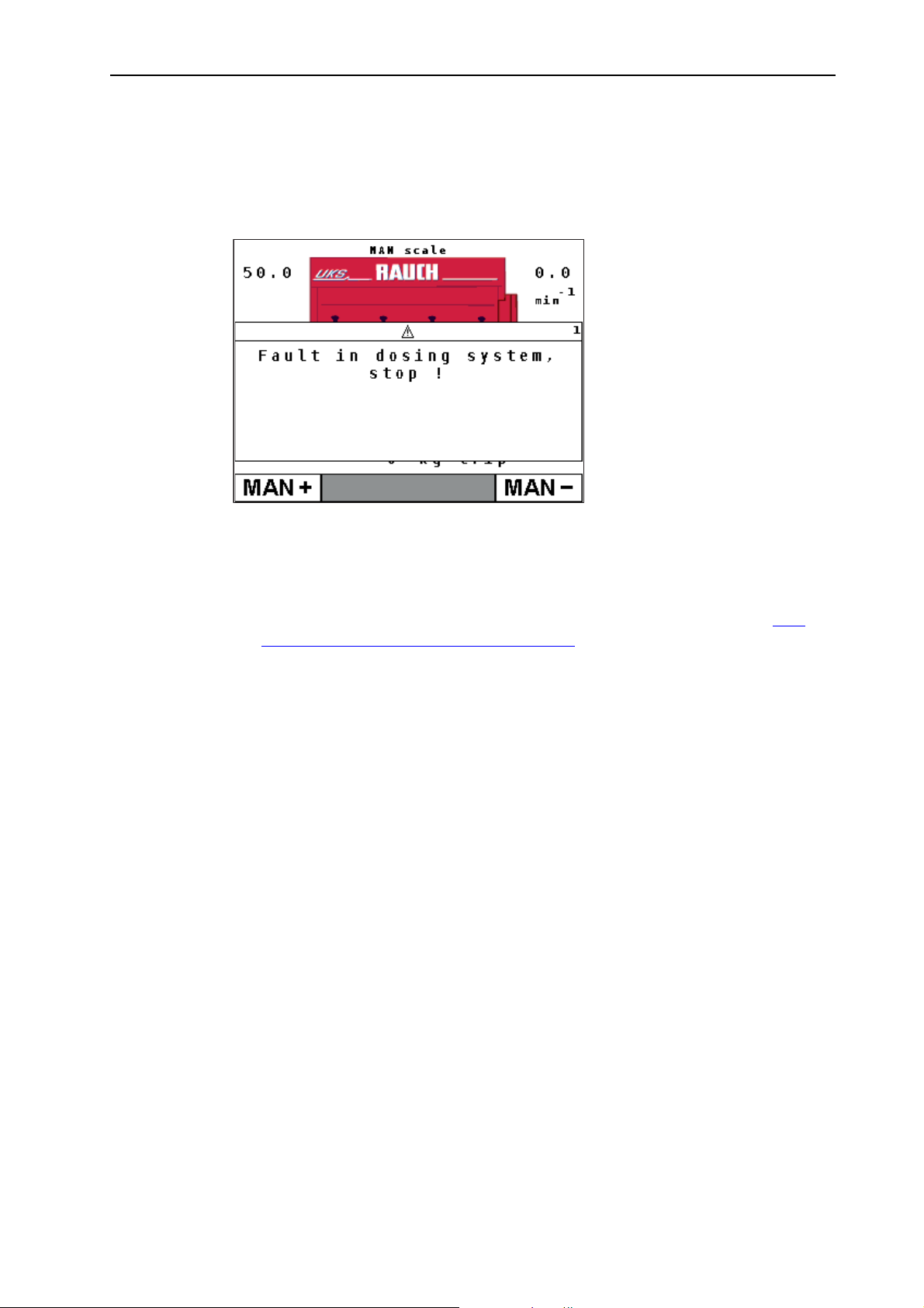
6.2 Clearing an error/alarm
6.2.1 Acknowledging an alarm message
Alarm messages are highlighted on the display and displayed with a warning
symbol.
Alarm messages and possible causes
6
Figure 6.1: Alarm message (e.g. dosing system)
Acknowledging an alarm message:
1. Correct the cause of the alarm message.
Refer to the operator’s manual of the fertiliser spreader and section 6.1:
Meaning of the alarm messages, page 69.
2. Press the C/100% key
The alarm message is cleared.
71
Page 78

Alarm messages and possible causes 6
72
Page 79
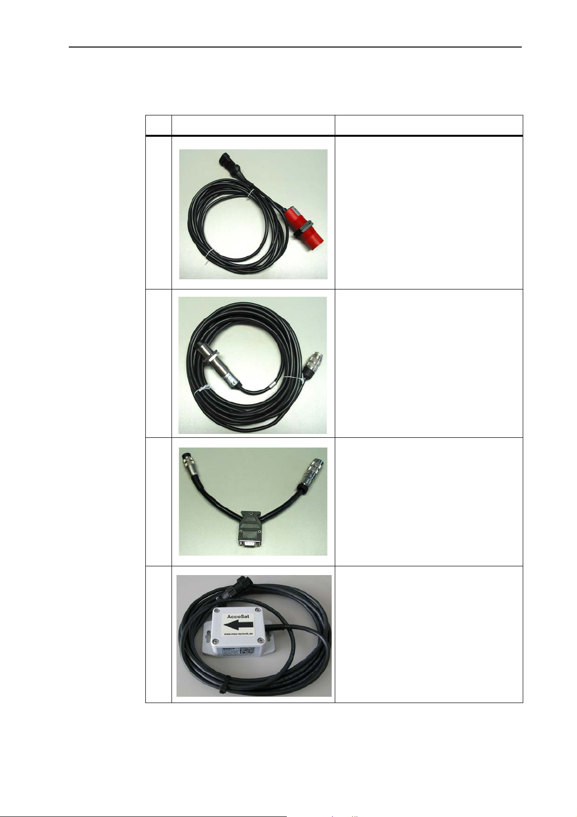
7 Special equipment
No. Illustration Designation
1 Level sensor
2 Forward speed sensor for
Special equipment
QUANTRON-A
7
3 Y cable RS232 for data exchange (e.g.
GPS, N sensor, etc.)
4 GPS cable and receiver
73
Page 80

Special equipment 7
74
Page 81

Index
Index
A
Alarm messages
Application rate 12, 31
Change
Residual material
Application rate adjustment 12
B
Brightness
C
Calibration
Calibration test 34
Working speed
Connection 15, 17
Example
Power supply
Socket
Control unit
Attachment 15
Connection
Connection diagram
Display
Machine serial number
operation
D
Display
Display configuration 56, 58
Display field 12, 58
E
Enter key
56
41
15
9
7, 9
8
69
40
65
34
18–20
15
15, 17
18–20
17
21–64
Forward speed 45
calibration
Signal source
simulated
Function key 8
K
Key
Arrow keys 8
Menu
key
Clear/Reset 8
Enter
ESC
Function key
kg key
Menu
ON/OFF
Start/Stop
T key
kg key 8
L
Language
Level sensor 59
LINUS 11
M
Machine configurat.
Application rate 40
Operating mode
Tractor
Main menu 56
Menu key
41
42
12
23
8
8
8
8
8
7
7
7
56–57
40
23
40
F
Fast emptying
Faults 69
Fertiliser 21
Fertiliser chart
copy 39
creation
delete
Fertiliser settings
Application rate 31
Field data 51
50
38
39
Menu
Navigation 3, 8, 23
Menu key 8
Menu overview
Fertiliser spreaders 14
Winter service
Metering slide 9
Test points
Mode 56
Mounting bracket 17
13
59–60
A
Page 82

Index
N
Navigation
Keys & buttons 8
O
Operating mode
AUTO km/h
MAN km/h
MAN scale
Operating screen 9
11
LINUS
UKS fertiliser spreader
UKS winter service
Operation 21–64
Overwriting 63
R
Residual material
RPM 11
Warning icon
S
Special equipment
Special functions
Text input 63
Spreading density 29
Spreading material settings
Spreading density 29
Spreading operation 65
AUTO km/h
MAN km/h
MAN scale
Residual material
11, 40
45, 66
45, 67
46, 68
11
9
65
12
73
66
67
68
65
Structural menu overview
Fertiliser spreaders 14
Winter service
System/test 56, 59
Brightness
Display configuration
Language
Mode
56
Test/diagnosis
T
Test/diagnosis
Level sensor
Metering slide
Test points
Voltage
Text input 63
63
delete
Tractor 40
Requirement
U
UKS
9, 11
V
Voltage
W
Weighing trip counter
Working speed 34
59
13
56
56
56–57
56
56, 59–60
59
59–60
59
59
15
8
B
Page 83

Terms/conditions of warranty
RAUCH units are manufactured with modern production methods and with the
greatest care and are subject to numerous inspections.
Therefore RAUCH offers a 12-month warranty subject to the following conditions:
The warranty begins on the date of purchase.
The warranty covers material and manufacturing faults. Our liability for third-
party products (hydraulic system, electronics) is limited to the warranty of the
manufacturer of the equipment. During the warranty period, manufacturing
and material faults are corrected free of charge by replacement or repair of
the affected parts. Other rights extending beyond the above, such as claims
for conversion, reduction or replacement for damages that did not occur in the
object of supply are explicitly excluded. Warranty services are provided by
authorised workshops, by RAUCH factory representatives or the factory.
The following are excluded from coverage by the warranty: natural wear, dirt,
corrosion and all faults caused by improper handing and external causes. The
warranty is rendered void if the owner carries out repairs or modifications to
the original state of the supplied product. Warranty claims are rendered void
if RAUCH original spare parts were not used. Therefore, the directions in the
operating manual must be observed. In all cases of doubt contact our sales
representatives or the factory directly. Warranty claims must be submitted to
the factory by 30 days at the latest after occurrence of the problem. The date
of purchase and the serial number must be indicated. If repairs under the warranty are required, they must be carried out by the authorised workshop only
after consultation with RAUCH or the company's appointed representatives.
The warranty period is not extended by work carried out under warranty.
Shipping faults are not factory faults and therefore are not part of the warranty
obligation of the manufacturer.
Terms/conditions of warranty
No claims for compensation for damages that are not part of RAUCH ma-
chines themselves will be accepted. This also means that no liability will be
accepted for damage resulting from spreading errors. Unauthorised modifications of RAUCH machines may result in consequential damage, for which the
manufacturer will not accept any liability. The manufacturer's liability exclusion will not apply in case of wilful intent or gross negligence by the owner or
a senior employee, and in cases where – according to the product liability law
– there is liability for personal injury or material damage to privately used objects in the event of defects in the supplied product. It will also not apply in the
event that assured properties are absent, if the purpose of the assured properties was to protect the purchaser against damage that does not involve the
supplied product itself.
Page 84

 Loading...