

Page 1
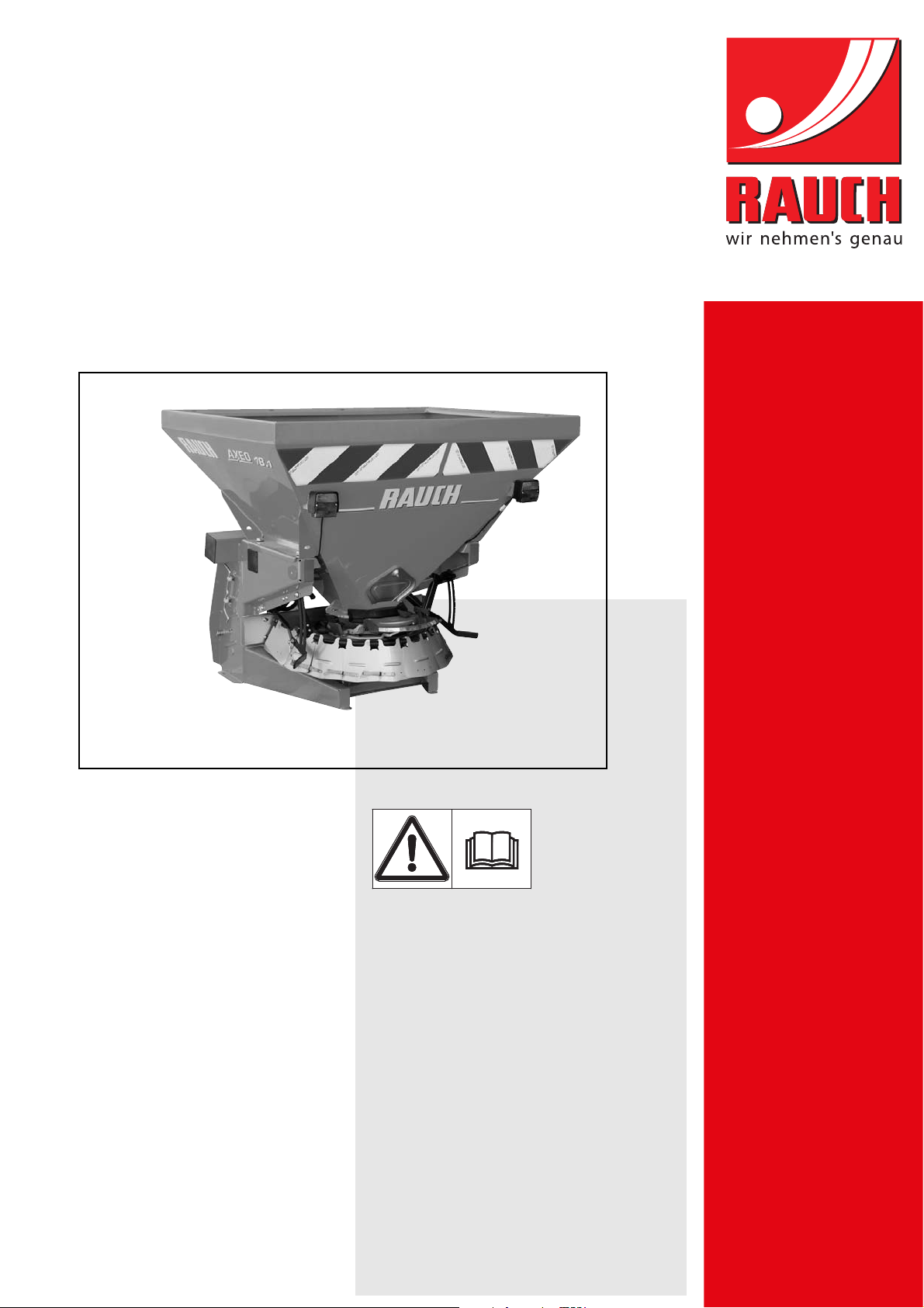
INSTRUCTION MANUAL
Please read carefully
before using the machine.
Keep for future reference.
This instruction manual/assembly instruction is to be considered as part of
the machine. Suppliers of new and second-hand machines are required to
document in writing that the instruction manual/assembly instruction was
delivered with the machine and handed over to the customer.
AXEO 2.1/16.1/18.1
Original instructions
5900854-e-en-0114
Page 2
Preface
Dear Customer
By purchasing the single-disc spreader of the AXEO series you have shown confidence in our
product. Thank you very much! We want to justify this confidence. You have purchased a powerful
and reliable machine.
However, in case unexpected problems arise: Our customer service is always there for you.
Please read this operator's manual carefully before commissioning the single-disc spreader and follow the advice given.
This operator's manual gives detailed instructions on the operation of the machine, as well as valuable information on assembly, maintenance, and care.
This manual may also describe equipment that is not included in your machine.
Please note that damage caused by incorrect operation or improper use is not covered by warranty claims.
n CAUTION
Please enter the type and serial number together with the year of manufacture of your single-disc spreader here.
This information can be obtained from the nameplate and/or at the frame.
Please always state this information when ordering spare parts or accessories,
and in case of complaints.
Type Serial number Year of construction
Technical improvements
We are continuously improving our products. Therefore, we reserve the right to make any
improvements and changes to our machine that we consider necessary without notice.
This constitutes no obligation to make such improvements or changes on machines that
have already been sold.
We will be pleased to answer any other questions that you might have.
Yours sincerely
RAUCH
Landmaschinenfabrik GmbH
Page 3

Table of Contents
Preface
Technical improvements
1 Intended use and EU declaration of conformity 1
1.1 Intended use . . . . . . . . . . . . . . . . . . . . . . . . . . . . . . . . . . . . . . . . . . . . . . . . . . . . . . . 1
1.2 Declaration of conformity. . . . . . . . . . . . . . . . . . . . . . . . . . . . . . . . . . . . . . . . . . . . . . 2
2 User instructions 3
2.1 About this operator’s manual. . . . . . . . . . . . . . . . . . . . . . . . . . . . . . . . . . . . . . . . . . . 3
2.2 Structure of the operator’s manual . . . . . . . . . . . . . . . . . . . . . . . . . . . . . . . . . . . . . . 3
2.3 Notes on text descriptions . . . . . . . . . . . . . . . . . . . . . . . . . . . . . . . . . . . . . . . . . . . . . 4
2.3.1 Instructions and procedures. . . . . . . . . . . . . . . . . . . . . . . . . . . . . . . . . . . . . . 4
2.3.2 Listings. . . . . . . . . . . . . . . . . . . . . . . . . . . . . . . . . . . . . . . . . . . . . . . . . . . . . . 4
2.3.3 References. . . . . . . . . . . . . . . . . . . . . . . . . . . . . . . . . . . . . . . . . . . . . . . . . . . 4
3 Safety 5
3.1 General Information . . . . . . . . . . . . . . . . . . . . . . . . . . . . . . . . . . . . . . . . . . . . . . . . . . 5
3.2 Significance of warnings . . . . . . . . . . . . . . . . . . . . . . . . . . . . . . . . . . . . . . . . . . . . . . 5
3.3 General information on the safety of the machine. . . . . . . . . . . . . . . . . . . . . . . . . . . 7
3.4 Instructions for the operator. . . . . . . . . . . . . . . . . . . . . . . . . . . . . . . . . . . . . . . . . . . . 7
3.4.1 Personnel qualifications . . . . . . . . . . . . . . . . . . . . . . . . . . . . . . . . . . . . . . . . . 7
3.4.2 Instruction. . . . . . . . . . . . . . . . . . . . . . . . . . . . . . . . . . . . . . . . . . . . . . . . . . . . 7
3.4.3 Accident prevention . . . . . . . . . . . . . . . . . . . . . . . . . . . . . . . . . . . . . . . . . . . . 8
3.5 Information on operational safety . . . . . . . . . . . . . . . . . . . . . . . . . . . . . . . . . . . . . . . 8
3.5.1 Lifting and moving the machine . . . . . . . . . . . . . . . . . . . . . . . . . . . . . . . . . . . 8
3.5.2 Parking the machine . . . . . . . . . . . . . . . . . . . . . . . . . . . . . . . . . . . . . . . . . . . 8
3.5.3 Filling the machine . . . . . . . . . . . . . . . . . . . . . . . . . . . . . . . . . . . . . . . . . . . . . 9
3.5.4 Checks before start-up. . . . . . . . . . . . . . . . . . . . . . . . . . . . . . . . . . . . . . . . . . 9
3.5.5 Hazard zone. . . . . . . . . . . . . . . . . . . . . . . . . . . . . . . . . . . . . . . . . . . . . . . . . 10
3.5.6 Operation . . . . . . . . . . . . . . . . . . . . . . . . . . . . . . . . . . . . . . . . . . . . . . . . . . . 11
3.6 Use of spreading material . . . . . . . . . . . . . . . . . . . . . . . . . . . . . . . . . . . . . . . . . . . . 12
3.7 Hydraulic system . . . . . . . . . . . . . . . . . . . . . . . . . . . . . . . . . . . . . . . . . . . . . . . . . . . 12
3.8 Maintenance and service. . . . . . . . . . . . . . . . . . . . . . . . . . . . . . . . . . . . . . . . . . . . . 13
3.8.1 Qualifications of maintenance staff . . . . . . . . . . . . . . . . . . . . . . . . . . . . . . . 13
3.8.2 Wear parts . . . . . . . . . . . . . . . . . . . . . . . . . . . . . . . . . . . . . . . . . . . . . . . . . . 13
3.8.3 Maintenance and service work. . . . . . . . . . . . . . . . . . . . . . . . . . . . . . . . . . . 13
3.9 Safety in traffic. . . . . . . . . . . . . . . . . . . . . . . . . . . . . . . . . . . . . . . . . . . . . . . . . . . . . 14
3.9.1 Checks before driving . . . . . . . . . . . . . . . . . . . . . . . . . . . . . . . . . . . . . . . . . 14
3.9.2 Transportation drive with the machine . . . . . . . . . . . . . . . . . . . . . . . . . . . . . 15
3.10 Safety equipment at the machine . . . . . . . . . . . . . . . . . . . . . . . . . . . . . . . . . . . . . . 16
3.10.1 Position of safety equipment . . . . . . . . . . . . . . . . . . . . . . . . . . . . . . . . . . . . 16
3.10.2 Function of safety equipment. . . . . . . . . . . . . . . . . . . . . . . . . . . . . . . . . . . . 18
3.11 Warning and instruction stickers . . . . . . . . . . . . . . . . . . . . . . . . . . . . . . . . . . . . . . . 19
3.11.1 Warning stickers. . . . . . . . . . . . . . . . . . . . . . . . . . . . . . . . . . . . . . . . . . . . . . 20
3.11.2 Instruction stickers and nameplate. . . . . . . . . . . . . . . . . . . . . . . . . . . . . . . . 21
3.12 Lighting system with reflector and sidelights . . . . . . . . . . . . . . . . . . . . . . . . . . . . . . 22
I
Page 4

Table of Contents
4 Technical data 23
4.1 Manufacturer . . . . . . . . . . . . . . . . . . . . . . . . . . . . . . . . . . . . . . . . . . . . . . . . . . . . . . 23
4.2 Description of the machine. . . . . . . . . . . . . . . . . . . . . . . . . . . . . . . . . . . . . . . . . . . . 24
4.2.1 Assembly overview, rear (all machine types) . . . . . . . . . . . . . . . . . . . . . . . . 24
4.2.2 Assembly overview, front, PTO drive . . . . . . . . . . . . . . . . . . . . . . . . . . . . . . 25
4.2.3 Assembly overview, front, hydraulic drive. . . . . . . . . . . . . . . . . . . . . . . . . . . 25
4.2.4 Assembly overview, HydroControl (-HC) . . . . . . . . . . . . . . . . . . . . . . . . . . . 26
4.3 Versions . . . . . . . . . . . . . . . . . . . . . . . . . . . . . . . . . . . . . . . . . . . . . . . . . . . . . . . . . . 27
4.3.1 Drive with universal drive shaft. . . . . . . . . . . . . . . . . . . . . . . . . . . . . . . . . . . 27
4.3.2 Drive with hydraulic motor . . . . . . . . . . . . . . . . . . . . . . . . . . . . . . . . . . . . . . 27
4.4 Technical data of basic equipment. . . . . . . . . . . . . . . . . . . . . . . . . . . . . . . . . . . . . . 29
4.5 Technical data of extensions and extension combinations . . . . . . . . . . . . . . . . . . . 30
5 Transportation without tractor 31
5.1 General safety instructions. . . . . . . . . . . . . . . . . . . . . . . . . . . . . . . . . . . . . . . . . . . . 31
5.2 Loading and unloading, parking . . . . . . . . . . . . . . . . . . . . . . . . . . . . . . . . . . . . . . . . 31
6 Commissioning 33
6.1 Accepting the machine . . . . . . . . . . . . . . . . . . . . . . . . . . . . . . . . . . . . . . . . . . . . . . . 33
6.2 Requirements for the tractor. . . . . . . . . . . . . . . . . . . . . . . . . . . . . . . . . . . . . . . . . . . 34
6.3 Mounting the universal drive shaft (versions H, Q, C) . . . . . . . . . . . . . . . . . . . . . . . 35
6.3.1 Checking the length of the universal drive shaft. . . . . . . . . . . . . . . . . . . . . . 35
6.3.2 Fitting / removing the universal drive shaft . . . . . . . . . . . . . . . . . . . . . . . . . . 36
6.4 Installing the machine on the tractor . . . . . . . . . . . . . . . . . . . . . . . . . . . . . . . . . . . . 39
6.4.1 Preconditions . . . . . . . . . . . . . . . . . . . . . . . . . . . . . . . . . . . . . . . . . . . . . . . . 39
6.4.2 Attaching the machine . . . . . . . . . . . . . . . . . . . . . . . . . . . . . . . . . . . . . . . . . 39
6.5 Connecting the hydraulic drive (Version H-100/200, Q-100/200, C-100/200,
Q-100/200-HC). . . . . . . . . . . . . . . . . . . . . . . . . . . . . . . . . . . . . . . . . . . . . . . . . . . . . 43
6.6 Connecting the metering slide actuator . . . . . . . . . . . . . . . . . . . . . . . . . . . . . . . . . . 44
6.6.1 Connecting the hydraulic metering slide actuator (Version H) . . . . . . . . . . . 44
6.6.2 Connecting the electronic metering slide actuator: AXEO, Version Q . . . . . 44
6.6.3 Connecting the electrical metering slide actuator: Version C . . . . . . . . . . . . 45
6.7 Connecting the actuator for the spreading width limiter (Version H) . . . . . . . . . . . . 45
6.8 Connecting the lighting. . . . . . . . . . . . . . . . . . . . . . . . . . . . . . . . . . . . . . . . . . . . . . . 45
6.9 Filling the machine . . . . . . . . . . . . . . . . . . . . . . . . . . . . . . . . . . . . . . . . . . . . . . . . . . 46
6.10 Parking and unhitching the machine . . . . . . . . . . . . . . . . . . . . . . . . . . . . . . . . . . . . 47
II
Page 5

Table of Contents
7 Machine settings 49
7.1 Setting options overview . . . . . . . . . . . . . . . . . . . . . . . . . . . . . . . . . . . . . . . . . . . . . 49
7.2 Spreading disc and agitator speed adjustment . . . . . . . . . . . . . . . . . . . . . . . . . . . . 51
7.2.1 PTO drive . . . . . . . . . . . . . . . . . . . . . . . . . . . . . . . . . . . . . . . . . . . . . . . . . . . 51
7.2.2 Drive with hydraulic motor (Version H-100/200, Q-100/200, C-100/200). . . 51
7.3 Adjusting the application rate. . . . . . . . . . . . . . . . . . . . . . . . . . . . . . . . . . . . . . . . . . 53
7.4 Adjusting the drop point. . . . . . . . . . . . . . . . . . . . . . . . . . . . . . . . . . . . . . . . . . . . . . 55
7.5 Adjusting the spreading width limiter . . . . . . . . . . . . . . . . . . . . . . . . . . . . . . . . . . . . 57
7.6 Adjustment options with HydroControl (Version Q-100/200-HC). . . . . . . . . . . . . . . 58
7.7 Adjusting the half-side slide. . . . . . . . . . . . . . . . . . . . . . . . . . . . . . . . . . . . . . . . . . . 59
7.8 Setting the spreading vanes . . . . . . . . . . . . . . . . . . . . . . . . . . . . . . . . . . . . . . . . . . 61
7.8.1 Increasing the spreading density on the right-hand side in the direction
of travel . . . . . . . . . . . . . . . . . . . . . . . . . . . . . . . . . . . . . . . . . . . . . . . . . . . . 61
7.8.2 Increasing the spreading density on the left-hand side in the direction
of travel . . . . . . . . . . . . . . . . . . . . . . . . . . . . . . . . . . . . . . . . . . . . . . . . . . . . 62
7.9 Use the fertiliser chart . . . . . . . . . . . . . . . . . . . . . . . . . . . . . . . . . . . . . . . . . . . . . . . 63
7.9.1 Information on the fertiliser chart . . . . . . . . . . . . . . . . . . . . . . . . . . . . . . . . . 63
7.9.2 List of fertiliser charts . . . . . . . . . . . . . . . . . . . . . . . . . . . . . . . . . . . . . . . . . . 64
7.9.3 Fertiliser chart for grit (3/5 mm) . . . . . . . . . . . . . . . . . . . . . . . . . . . . . . . . . . 65
7.9.4 Fertiliser chart for sand . . . . . . . . . . . . . . . . . . . . . . . . . . . . . . . . . . . . . . . . 66
7.9.5 Fertiliser chart for rock salt. . . . . . . . . . . . . . . . . . . . . . . . . . . . . . . . . . . . . . 67
7.9.6 Fertiliser chart for refined salt. . . . . . . . . . . . . . . . . . . . . . . . . . . . . . . . . . . . 68
7.9.7 Fertiliser chart for fertiliser . . . . . . . . . . . . . . . . . . . . . . . . . . . . . . . . . . . . . . 69
7.10 Calibration . . . . . . . . . . . . . . . . . . . . . . . . . . . . . . . . . . . . . . . . . . . . . . . . . . . . . . . . 84
7.10.1 Determining the nominal output rate . . . . . . . . . . . . . . . . . . . . . . . . . . . . . . 84
7.10.2 Implementing the calibration . . . . . . . . . . . . . . . . . . . . . . . . . . . . . . . . . . . . 85
8 Spreading work 87
8.1 General information . . . . . . . . . . . . . . . . . . . . . . . . . . . . . . . . . . . . . . . . . . . . . . . . . 87
8.2 General information on the agitator . . . . . . . . . . . . . . . . . . . . . . . . . . . . . . . . . . . . . 88
8.3 Instructions regarding the spreading operation . . . . . . . . . . . . . . . . . . . . . . . . . . . . 89
8.4 Spreading grit . . . . . . . . . . . . . . . . . . . . . . . . . . . . . . . . . . . . . . . . . . . . . . . . . . . . . 90
8.5 Spreading of sand or moist salt . . . . . . . . . . . . . . . . . . . . . . . . . . . . . . . . . . . . . . . . 91
8.6 Spreading of salt . . . . . . . . . . . . . . . . . . . . . . . . . . . . . . . . . . . . . . . . . . . . . . . . . . . 92
8.7 Spreading granulated fertiliser. . . . . . . . . . . . . . . . . . . . . . . . . . . . . . . . . . . . . . . . . 93
8.8 Spreading grit-salt mixtures. . . . . . . . . . . . . . . . . . . . . . . . . . . . . . . . . . . . . . . . . . . 94
8.9 Discharging residual material . . . . . . . . . . . . . . . . . . . . . . . . . . . . . . . . . . . . . . . . . 95
III
Page 6

Table of Contents
9 Maintenance and service 97
9.1 Safety . . . . . . . . . . . . . . . . . . . . . . . . . . . . . . . . . . . . . . . . . . . . . . . . . . . . . . . . . . . .97
9.2 Wear parts and screw connections . . . . . . . . . . . . . . . . . . . . . . . . . . . . . . . . . . . . . 97
9.2.1 Checking wear parts . . . . . . . . . . . . . . . . . . . . . . . . . . . . . . . . . . . . . . . . . . . 97
9.2.2 Checking screw connections . . . . . . . . . . . . . . . . . . . . . . . . . . . . . . . . . . . . 98
9.3 Cleaning . . . . . . . . . . . . . . . . . . . . . . . . . . . . . . . . . . . . . . . . . . . . . . . . . . . . . . . . . . 98
9.4 Metering slide adjustment . . . . . . . . . . . . . . . . . . . . . . . . . . . . . . . . . . . . . . . . . . . . 99
9.5 Checking the agitator for wear . . . . . . . . . . . . . . . . . . . . . . . . . . . . . . . . . . . . . . . . 101
9.5.1 Dismounting the agitator. . . . . . . . . . . . . . . . . . . . . . . . . . . . . . . . . . . . . . . 101
9.5.2 Checking agitator RWK AX 140 for wear . . . . . . . . . . . . . . . . . . . . . . . . . . 102
9.5.3 Checking agitator RWK AX 160 for wear . . . . . . . . . . . . . . . . . . . . . . . . . . 102
9.5.4 Checking agitator RWK AX 180 for wear . . . . . . . . . . . . . . . . . . . . . . . . . . 103
9.5.5 Checking agitator RWK AX 220 for wear . . . . . . . . . . . . . . . . . . . . . . . . . . 104
9.5.6 Checking agitator RWK AX 240 for wear . . . . . . . . . . . . . . . . . . . . . . . . . . 105
9.5.7 Checking the thrust ring for wear . . . . . . . . . . . . . . . . . . . . . . . . . . . . . . . . 105
9.5.8 Checking the stop ring in the hopper for wear . . . . . . . . . . . . . . . . . . . . . . 106
9.6 Replacing the spreader vanes . . . . . . . . . . . . . . . . . . . . . . . . . . . . . . . . . . . . . . . . 106
9.7 Transmission oil . . . . . . . . . . . . . . . . . . . . . . . . . . . . . . . . . . . . . . . . . . . . . . . . . . . 107
9.7.1 Quantity and types . . . . . . . . . . . . . . . . . . . . . . . . . . . . . . . . . . . . . . . . . . . 107
9.7.2 Checking the oil level . . . . . . . . . . . . . . . . . . . . . . . . . . . . . . . . . . . . . . . . . 108
9.8 Lubrication plan . . . . . . . . . . . . . . . . . . . . . . . . . . . . . . . . . . . . . . . . . . . . . . . . . . . 109
10 Faults and possible causes 111
11 List of available accessories 113
11.1 Electrical remote control (metering slide and spreading width limiter) . . . . . . . . . . 113
11.2 Hydraulic remote control (metering slide). . . . . . . . . . . . . . . . . . . . . . . . . . . . . . . . 113
11.3 Extensions . . . . . . . . . . . . . . . . . . . . . . . . . . . . . . . . . . . . . . . . . . . . . . . . . . . . . . . 113
11.4 Hopper cover . . . . . . . . . . . . . . . . . . . . . . . . . . . . . . . . . . . . . . . . . . . . . . . . . . . . . 113
11.5 Spreader apron . . . . . . . . . . . . . . . . . . . . . . . . . . . . . . . . . . . . . . . . . . . . . . . . . . . 114
11.6 Agitators . . . . . . . . . . . . . . . . . . . . . . . . . . . . . . . . . . . . . . . . . . . . . . . . . . . . . . . . . 114
11.6.1 RWK AX 140. . . . . . . . . . . . . . . . . . . . . . . . . . . . . . . . . . . . . . . . . . . . . . . . 114
11.6.2 RWK AX 160. . . . . . . . . . . . . . . . . . . . . . . . . . . . . . . . . . . . . . . . . . . . . . . . 114
11.6.3 RWK AX 180. . . . . . . . . . . . . . . . . . . . . . . . . . . . . . . . . . . . . . . . . . . . . . . . 115
11.6.4 RWK AX 220. . . . . . . . . . . . . . . . . . . . . . . . . . . . . . . . . . . . . . . . . . . . . . . . 115
11.6.5 RWK AX 240. . . . . . . . . . . . . . . . . . . . . . . . . . . . . . . . . . . . . . . . . . . . . . . . 116
11.7 Adapter for attachment at category 1N . . . . . . . . . . . . . . . . . . . . . . . . . . . . . . . . . 116
11.8 BLO 18 lighting. . . . . . . . . . . . . . . . . . . . . . . . . . . . . . . . . . . . . . . . . . . . . . . . . . . . 116
11.9 Universal drive shaft with ratchet clutch. . . . . . . . . . . . . . . . . . . . . . . . . . . . . . . . . 116
IV
Page 7

Table of Contents
12 Disposal 117
12.1 Safety. . . . . . . . . . . . . . . . . . . . . . . . . . . . . . . . . . . . . . . . . . . . . . . . . . . . . . . . . . . 117
12.2 Disposal . . . . . . . . . . . . . . . . . . . . . . . . . . . . . . . . . . . . . . . . . . . . . . . . . . . . . . . . . 118
13 Axle load calculation 119
Index A
Terms/conditions of warranty
V
Page 8

Table of Contents
VI
Page 9

Intended use and EU declaration of conformity
1 Intended use and EU declaration of conformity
1.1 Intended use
The AXEO single-disc spreader may only be used in accordance with the information given in this operator's manual.
The AXEO single-disc spreader has been constructed for the following applications (intended use) exclusively:
in winter road maintenance for spreading material that can be delivered by
chute, such as grit (3/5), sand and salt,
in agriculture for spreading dry, granular and crystalline fertilisers,
Any use outside these definitions is considered misuse. The manufacturer is not
liable for any damage which results from misuse. The operator bears the entire risk.
The intended use also includes compliance with the operating, maintenance, repair and servicing conditions prescribed by the manufacturer. Only genuine spare
parts from the manufacturer may be used as replacements.
The AXEO single-disc spreader may only be used, maintained and repaired by
instructed and trained staff who are familiar with the characteristics of the machine and who are aware of the risks.
1
Important information on the operation and safe handling of the machine is provided in this operator's manual. The manufacturer also attaches warning notes
and warning symbols to the machine. All such information must be followed when
using the machine.
Moreover, the relevant accident prevention regulations and the other generally
recognised safety, occupational health, and road traffic regulations must be strictly observed when using the machine.
Unauthorized modifications to the single-disc spreader are not permitted. They
will exempt the manufacturer from liability for any damage resulting therefrom.
In the following chapters, the single-disc spreader is referred to as “machine”.
Foreseeable misuse
The manufacturer provides warning notes and signs on the AXEO single-disc
spreader relating to foreseeable misuse. These warning notes and signs must be
observed under all circumstances in order to prevent the AXEO single-disc
spreader from being used for any other purpose than that specified in the operator's manual.
1
Page 10

Intended use and EU declaration of conformity 1
Muster
S ample
Spécimen
1.2 Declaration of conformity
In accordance with 2006/42/EC, Appendix II, No. 1.A
Rauch - Landmaschinenfabrik GmbH,
Landstrasse 14, 76547 Sinzheim, Germany
We hereby declare that the product:
Single-disc spreader of the series AXEO
Type: AXEO 2.1, AXEO 6.1, AXEO 18.1
complies with all relevant regulations of the EC Machinery Directive 2006/42/EC.
Technical documents compiled by:
Rauch - Design Management
Landstrasse 14, 76547 Sinzheim, Germany
(Norbert Rauch - Managing director)
2
Page 11

2 User instructions
2.1 About this operator’s manual
This operator's manual is an integral part of the AXEO single-disc spreader.
The operator’s manual contains important information for a safe, appropriate
and economic use and maintenance of the machine. Adherence to this operator’s manual helps to avoid risks, to reduce repair costs and downtime, and to
increase the machine's reliability and service life.
The complete documentation, comprising this operator's manual and any other
documents provided, must be kept in an easily accessible location close to where
the machine is used (e. g. in the tractor).
If the machine is sold, the operator's manual must also be passed on to the new
owner.
The operator's manual is intended for the operator of the machine of the AXEO
series and anyone involved in operating and maintaining it. The operator's manual must be read, understood, and applied by all persons entrusted with the following work on the machine:
User instructions
2
Operation,
Maintenance and cleaning,
Repairing faults.
The following are particularly important:
The chapter on safety,
The warnings in the text of the individual chapters.
The operator's manual does not replace your own responsibility as the operator and operating personnel of the control unit.
2.2 Structure of the operator’s manual
The operator's manual is divided into 6 points of focus:
General information,
Safety instructions,
Machine data,
Instructions on the operation of the machine,
Instructions on detecting and rectifying faults and
Maintenance and repair instructions.
3
Page 12

User instructions 2
2.3 Notes on text descriptions
2.3.1 Instructions and procedures
Steps that the operator must carry out are shown as a numbered list.
1. Instruction for action step 1
2. Instruction for action step 2
Instructions involving only one step are not numbered. The same applies for action steps that do not have a specific sequence.
A bullet is placed in front of these instructions:
Handling instruction
2.3.2 Listings
Listings without a specific sequence are shown with bullet points (level 1) and
dashes (level 2):
Property A
Property B
2.3.3 References
References to other text passages in the document are indicated with section
number, headline text and page number:
Example: See also Chapter 3: Safety,page 5.
References to other documents are indicated as note or instruction without exact
chapter or page number:
Example: Please also observe the instructions contained in the manual for
- Point A
- Point B
the universal drive shaft.
4
Page 13
3 Safety
3.1 General Information
The chapter Safety contains basic warning notes as well as working and traffic
safety instructions for the usage of the installed machine.
The adherence to the instructions in this chapter is a prerequisite for the safe handling and trouble-free operation of the machine.
There are additional warnings in the other chapters of this operator’s manual,
which must also be observed. The warning instructions are given before the text
for the relevant actions.
Warning notes on the supplier components can be found in the respective supplier documentation. These warning instructions must also be observed.
3.2 Significance of warnings
The warning instructions in this manual have been structured according to the degree of danger and the probability of their occurrence.
Safety
3
Danger signs and symbols inform the user about other construction-related and
unavoidable residual risks that may be encountered when operating the machine.
The warning notes used are structured as follows:
Signal word
Symbol Explanation
Example
n DANGER
Risk to life if warning is not observed
Description of the danger and possible consequences.
Ignoring these warnings will result in very serious or even fatal
injury.
Measures to prevent the danger.
5
Page 14
Safety 3
Warning severity level
The degree of danger is indicated by the signal word. The levels are classified as
follows:
n DANGER
Type and source of danger
This warning warns of a danger posing an immediate threat to the
health and life of persons.
Ignoring these warnings will result in very serious or even fatal
injury.
Always observe the measures described to prevent this
danger.
n WARNING
Type and source of danger
This warning warns of a possible dangerous situation for the
health of persons.
Ignoring these warnings will result in very serious injury.
Always observe the measures described to prevent this
danger.
n CAUTION
Type and source of danger
This warning warns of a potentially dangerous situation for personal health or of material and environmental damage.
Ignoring this warning can result in injuries and damage to the product or the general area.
Always observe the measures described to prevent this
danger.
NOTICE
General information containing application tips and particularly useful information, but which constitutes neither warnings nor hazards.
6
Page 15

3.3 General information on the safety of the machine
The machine is constructed in accordance with the state of the art and the recognized technical regulations. However, its usage and maintenance may cause
danger to the health and life of the operator or third parties and/or the impairment
of the machine and other material assets.
For this reason, the machine may only be operated
when it is in a proper and roadworthy condition,
being aware of safety and dangers.
For this purpose, it is essential that you know and apply the content of the operator's manual, the applicable accident prevention regulations as well as the general safety, occupational health and road-traffic regulations.
3.4 Instructions for the operator
It is the operator's responsibility that the machine is used as intended.
3.4.1 Personnel qualifications
Safety
3
Before starting any work on or with the machine, all persons who are involved in
operation, maintenance or repair must have read and understood this operator’s
manual.
The machine may only be operated by instructed personnel authorized by the
Members of staff who are still in training or subject to coaching/instructions
Only qualified maintenance staff may implement maintenance and service
3.4.2 Instruction
Distribution partners, works representatives or employees of RAUCH will instruct
the operator regarding the operation and maintenance of the machine.
The owner must ensure that newly recruited operating and maintenance personnel are instructed to the same extent and with the same care with regard to the
operation and repair of the machine in compliance with this operator’s manual.
owner.
may only work on the machine when an experienced person is present.
work.
7
Page 16

Safety 3
3.4.3 Accident prevention
Safety and accident prevention regulations are governed by law in every country.
The operator of the machine shall be responsible for the compliance with these
regulations applicable in the country of use.
The following instructions must also be observed:
Never let the machine run without supervision.
Do not ride on the machine while it is working or being transported (no pas-
sengers).
Do not use machine parts as climbing aids.
Always wear tight fitting clothes. Do not wear work clothes with belts, loose
threads or other items that could snag.
Follow the manufacturer's warning notes when handling chemicals. You may
have to wear personal protective equipment (PPE).
3.5 Information on operational safety
To avoid dangerous situations, only use the machine in a reliable condition.
3.5.1 Lifting and moving the machine
The machine is delivered ex works standing on a pallet.
Only lift the machine at the pallet using a suitable pallet truck or forklift. Take
the total weight into consideration.
Never lift or move the machine at the hopper or at other, non-marked anchor
points.
3.5.2 Parking the machine
Only park the machine with the hopper empty and on horizontal, solid ground.
If the machine is parked on its own (without tractor), fully open the metering
slide. The return spring is released and any water in the hopper can run out.
8
Page 17

3.5.3 Filling the machine
Only fill the machine when the motor of the tractor is stopped. Remove the
ignition key in order to ensure that the motor cannot be started.
Use suitable auxiliary equipment for filling the spreader (e.g. front-end loader,
auger, silo).
When manually filling it (e.g. loading it with big bags), use suitable steps.
Fill the machine no higher than the top-edge. Observe the maximum admis-
sible payload.
Only fill the machine when it is mounted.
Only fill the machine when the protective grid is closed. This way, faults during
spreading caused by lumps in the spreading material or other foreign bodies
are prevented.
3.5.4 Checks before start-up
Check the operating safety of the machine before the first and every subsequent
start-up.
Safety
3
Is the entire safety equipment installed at the machine and functional?
Are all fasteners and load-bearing connections tight and in proper condition?
Are the spreading disc, the spreading vanes and their fixings in proper condi-
tion?
Is the protective grid locked in the hopper?
Are all locks firmly closed?
Is the hazard zone of the machine clear of persons?
Is the universal drive shaft guard in good condition?
Check the mounting height. The distance from the lower edge of the frame to
the floor may not exceed 120 cm.
9
Page 18
Safety 3
3.5.5 Hazard zone
Ejected spreading material may cause serious injury (e. g. to the eyes).
When persons are present between the tractor and the machine, there is a great
hazard caused by the tractor rolling away or machine movements which may
have fatal consequences.
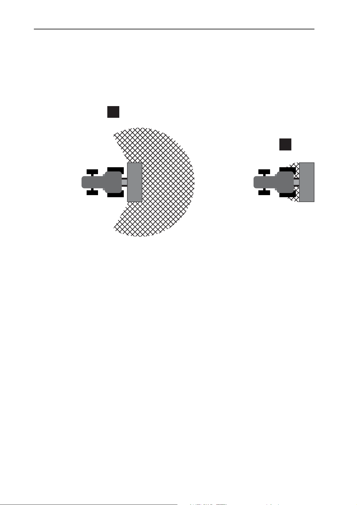
The following figure displays the hazard zones of the machine.
A
B
Figure 3.1: Hazard zones around attachment units
[A] Hazard zone in spreading operation
[B] Hazard zone when coupling/uncoupling the machine
For this reason, ensure that nobody is present in spreading range [A] of the
machine.
Immediately stop the machine and the tractor if persons are present in the
hazard zone of the machine.
When actuating the hydraulic lift, ensure that nobody is present in the hazard
zone [B].
10
Page 19

3.5.6 Operation
If the machine malfunctions, stop the machine immediately and secure it.
Never climb onto the machine while the spreader unit is running.
Only operate the machine with the protective grid in the hopper. The protec-
Only operate the machine with closed maintenance cover.
Rotating machine components can cause serious injury. For this reason, en-
Before setting the application rate, completely close the metering slide if the
Do not deposit any parts (such as screws, nuts) in the spreader hopper.
Ejected spreading material may cause serious injury (e. g. to the eyes). For
Safety
Have the fault repaired immediately by appropriately instructed and authorised personnel.
tive grid must not be removed during operation.
sure that you avoid any contact between body parts or clothes and rotating
components.
machine is equipped with a hydraulic metering slide actuator.
this reason, ensure that nobody is present in the spreading range of the machine.
3
If the wind speed is too high, stop spreading since the specified spreading
range can no longer be guaranteed under such conditions.
Never climb onto the machine or the tractor when it is situated beneath high-
voltage electrical power lines.
11
Page 20

Safety 3
3.6 Use of spreading material
Incorrect selection or use of spreading material may cause serious injury or environmental damage.
When selecting the spreading material, inform yourself about its effects on
persons, the environment, and the machine.
Follow the directions of the spreading material manufacturer exactly.
3.7 Hydraulic system
The hydraulic system is under high pressure.
Fluid escaping under high pressure can cause serious injuries and environmental
damage. The following instructions must be observed to prevent danger:
Always operate the machine below the permissible maximum operating pres-
sure.
Depressurise the hydraulic system before any maintenance work. Turn the
tractor motor off. Secure it against reactivation.
When looking for leaks, wear protective glasses and protective gloves at
all times.
In the case of injury in connection with hydraulic oil, consult a physician im-
mediately as severe infections may occur otherwise.
When connecting the hydraulic hoses to the tractor, ensure that the hydraulic
system is depressurised, both on the tractor and the machine side.
Attach the hydraulic hoses of the tractor and the spreader hydraulic systems
only with the prescribed connections.
Prevent any contamination of the hydraulic circuit. Always suspend the cou-
plings in the brackets provided. Use the dust caps. Clean the connections before joining them.
Regularly check the hydraulic components and hydraulic hose lines for me-
chanical defects, e.g. cuts and abrasions, contusions, bends, tears, porosity
etc.
Even when stored correctly and used within approved load limits, hoses and
hose couplings are subject to a natural ageing process. This limits their storage and service life.
The service life of the hose lines may not exceed 6 years, including a possible
storage time of maximally 2 years.
The date of manufacture of the hoses is indicated on the hose coupling in month
and year
12
Replace hydraulic hoses if damaged or aged.
Replacement of hydraulic hoses must meet the technical requirements of the
equipment manufacturer. In particular, note the different maximum pressure
ratings of replacement hoses.
Page 21

3.8 Maintenance and service
Maintenance and service work involves additional hazards that do not occur during operation of the machine.
Any maintenance and service work is to be conducted with increased alert-
ness at all times. Work particularly thoroughly and cautiously.
3.8.1 Qualifications of maintenance staff
Welding and work on the electrical and hydraulic systems is to be carried out
by qualified technicians only.
3.8.2 Wear parts
The maintenance and service intervals described in the present operator's
manual are to be strictly adhered to at all times.
Furthermore, the maintenance and service intervals of the supplier compo-
nents must also be complied with. See the supplier documentation for the relevant intervals.
Safety
3
We recommend that you have the condition of the machine checked after
each season by your specialist dealer, paying particular attention to its fixing
components, safety-relevant plastic components, hydraulics, metering parts
(such as metering slide and agitator), spreading vanes and spreading discs.
Spare parts must at least comply with the technical requirements specified by
the manufacturer. Compliance with technical requirements is ensured using
original spare parts.
Self-locking nuts are designed to be used only once. Always use new self-
locking nuts to fasten components (e.g. when replacing spreading vanes or
maintenance covers).
3.8.3 Maintenance and service work
Always switch off the tractor motor before any cleaning, maintenance and
service work and when troubleshooting. Wait until all rotating parts of the machine have come to a standstill.
Make sure that no unauthorised person can start the machine. Remove the
ignition key of the tractor.
Check that the tractor with the machine is correctly parked. Park them with an
empty hopper on level, solid ground and secure them to prevent them from
moving.
Additionally secure the lifted machine against falling down (e.g. by means of
a safety stand) when carrying out maintenance and repair work or inspections
under the lifted machine.
Release the pressure from the hydraulic system before any maintenance and
repair work.
Disconnect the power supply before working on the electrical system.
Only open the maintenance cover at the hopper if the machine has been de-
commissioned.
Only open the protective grid in the hopper if the machine has been decom-
missioned.
13
Page 22

Safety 3
If you have to work while the PTO shaft is rotating, make sure that nobody is
near the PTO or the drive shaft.
Only remove any clogging in the hopper while the machine is at a standstill
and never with your hand or foot; for this purpose, suitable tools must be
used. In order to avoid clogging, the hopper may only be filled when the protective grid is mounted.
Before cleaning the machine with water, steam jet or other cleaning agents,
cover all components that must not get wet (e.g. bearings, electrical connections).
Regularly check nuts and screws for tightness. Retighten loose connections.
3.9 Safety in traffic
When driving on public streets and roads, the tractor with the attached machine
must comply with the road traffic regulations of the respective country. The owner
and driver are responsible for compliance with these regulations.
3.9.1 Checks before driving
The pre-departure check is an important contribution to road safety. Before every
trip, check compliance with the operating conditions, traffic safety, and the regulations of the country of use.
Is the permissible total weight complied with? Note the permitted axle load,
the permitted braking load, and the permitted tyre load capacity; See also
“Axle load calculation“ on page 119.
Check the tyre pressures and the function of the tractor brake system.
Is the machine attached appropriately?
Could spreading material be lost while travelling?
- Check the filling level of the spreading material in the hopper.
- The metering slide must be closed.
- The ball valves must also be closed on single-acting hydraulic cylinders.
- Switch off the electronic control unit.
Does the lighting and marking of the machine comply with the regulations of
your country with respect to driving on public roads? Make sure that warning
signs, reflectors, and auxiliary lights are correctly placed.
14
Page 23

3.9.2 Transportation drive with the machine
The handling, tilting, steering, and braking performance of the tractor is affected
by the attached machine. For example, the high payload will reduce the weight
on the tractor's front axle and affect its steering.
Be aware of the changed driving behaviour.
When driving, always ensure that there is sufficient visibility. If vision is re-
stricted (e.g. when reversing), another person is required to direct the driver.
Observe the permissible maximum speed.
Avoid sudden turns when driving uphill or downhill or across a slope. By repo-
sitioning the gravity centre, there is a risk of toppling over. Special care is to
be taken when driving on uneven, soft ground (e. g. when entering fields, at
kerbs) as well.
Set the lower link on the three-point linkage so it is rigid to prevent the ma-
chine from rocking.
Passengers are prohibited on the machine during transport and operation.
Safety
3
15
Page 24
Safety 3
3.10 Safety equipment at the machine
3.10.1 Position of safety equipment
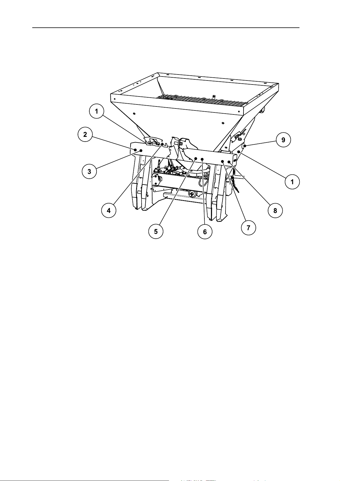
Figure 3.2: Position of safety equipment, warning and instruction notices, and
reflectors - front
[1] Instructions: Agitator stop
[2] Nameplate
[3] Serial number
[4] Retainer for cables and hoses
[5] Instructions: maximum payload
[6] Instructions: PTO speed
[7] Warning: read operator's manual
[8] Warning: ejection of material
[9] Yellow side reflectors
16
Page 25
Safety
3
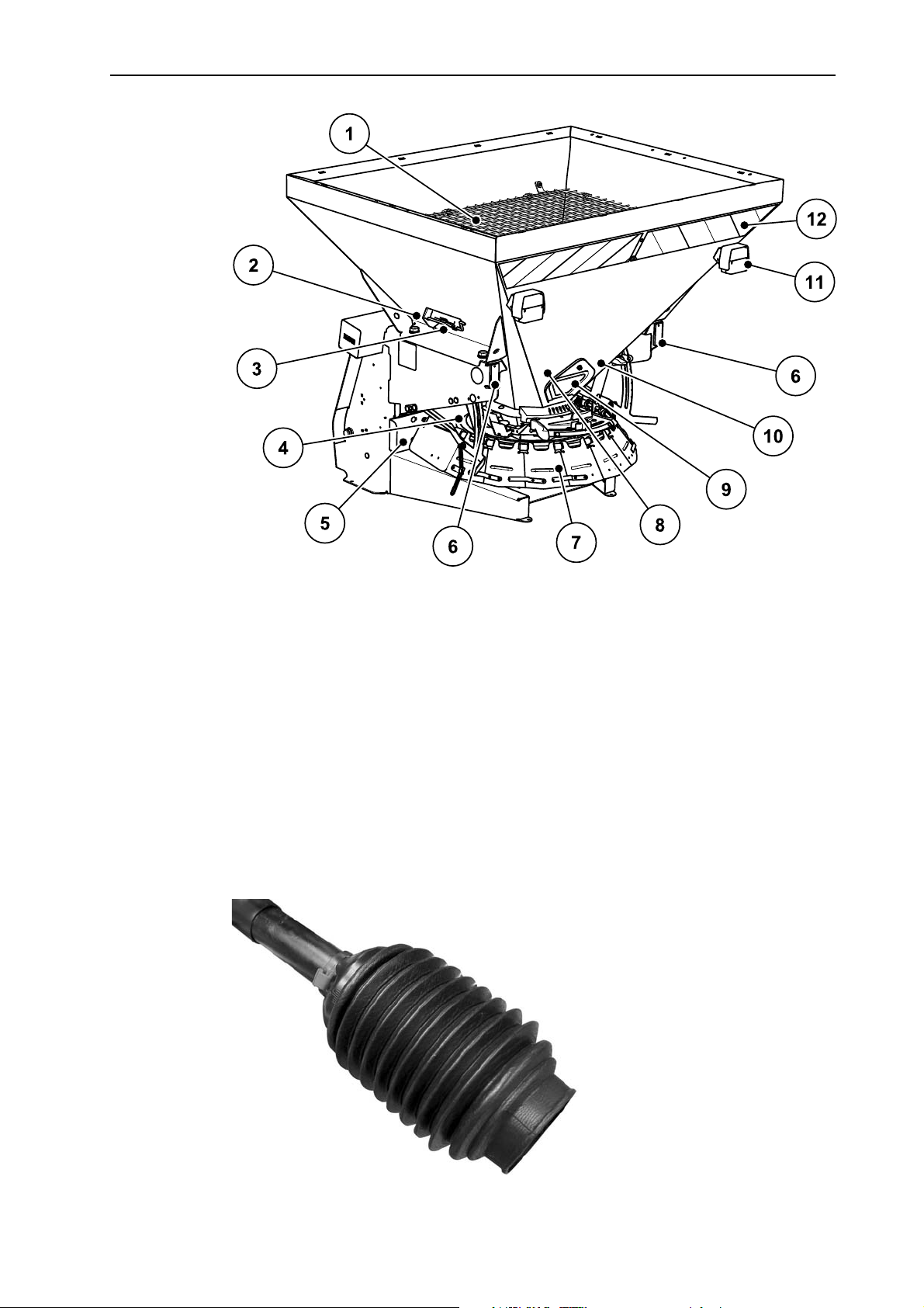
Figure 3.3: Position of safety equipment, warning and instruction notices, and
reflectors - rear
[1] Protective grid in the hopper
[2] Instructions: Tightening torque
[3] Adjustment lever
[4] Spreading disc cover
[5] Front spreading disc cover
[6] Red reflectors, rear
[7] Adjustable spreading disc cover (spreading width limiter)
[8] Warning: moving parts
[9] Maintenance cover
[10] Warning: remove ignition key
[11] Lighting cable, rear
[12] Warning foil
Figure 3.4: Drive shaft guard
17
Page 26

Safety 3
3.10.2 Function of safety equipment
The safety equipment is designed to protect your health and life.
Before working with the machine, ensure that the safety equipment is func-
tional.
Only operate the machine when the safety equipment is functional.
Designation Function
Protective grid in the
hopper
Prevents body parts from being pulled into the rotating
agitator.
Prevents body parts from being cut off by the metering
slide.
Prevents faults during spreading caused by lumps in the
spreading material, large stones or other large objects
(screening effect).
Maintenance cover Enables easy agitator replacement.
Front spreading disc
cover
Protection against getting caught by the rotating spreading disc from the front.
Prevents the spreading material from being ejected towards the front (in the direction of the tractor/workstation).
Adjustable spreading
disc cover (spreading
width limiter)
Protection against getting caught by the rotating spreading disc from the side and from behind.
Ensures the ejection of spreading material at the desired
spreading width.
Plastic cover for
spreading disc
Protection against getting caught by the rotating spreading disc from the top.
Drive shaft guard Prevents body parts from being pulled into the rotating
drive shaft.
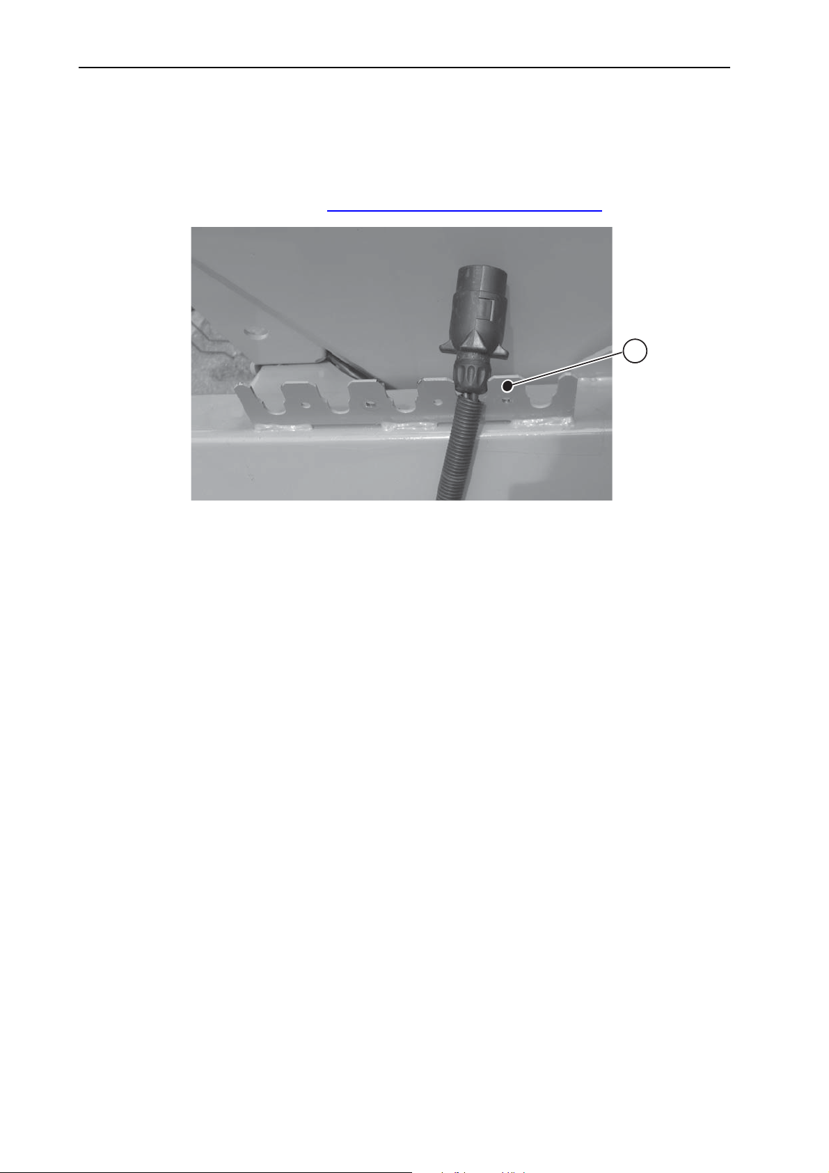
Retainer For securing the hoses and cables to the frame.
Prevents crushing or kinking the hoses and cables. Refer to figure 3.5
.
18
Page 27
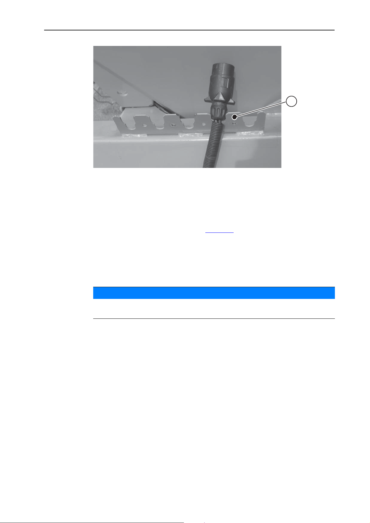
Figure 3.5: Retainer for cables and hoses
[1] Retainer for cables and hoses
Safety
1
3
3.11 Warning and instruction stickers
Various warning and instruction stickers are attached to the machine (for the position at the machine, please refer to figure 3.2
The warning and instruction stickers are components of the machine. They must
not be removed or modified. Missing or illegible signs must be replaced immediately.
If new components are installed during repairs, the same warning and instruction
stickers that were on the original parts must be placed on the new parts.
The correct warning and instruction stickers can be obtained from the spare
parts service.
).
NOTICE
19
Page 28
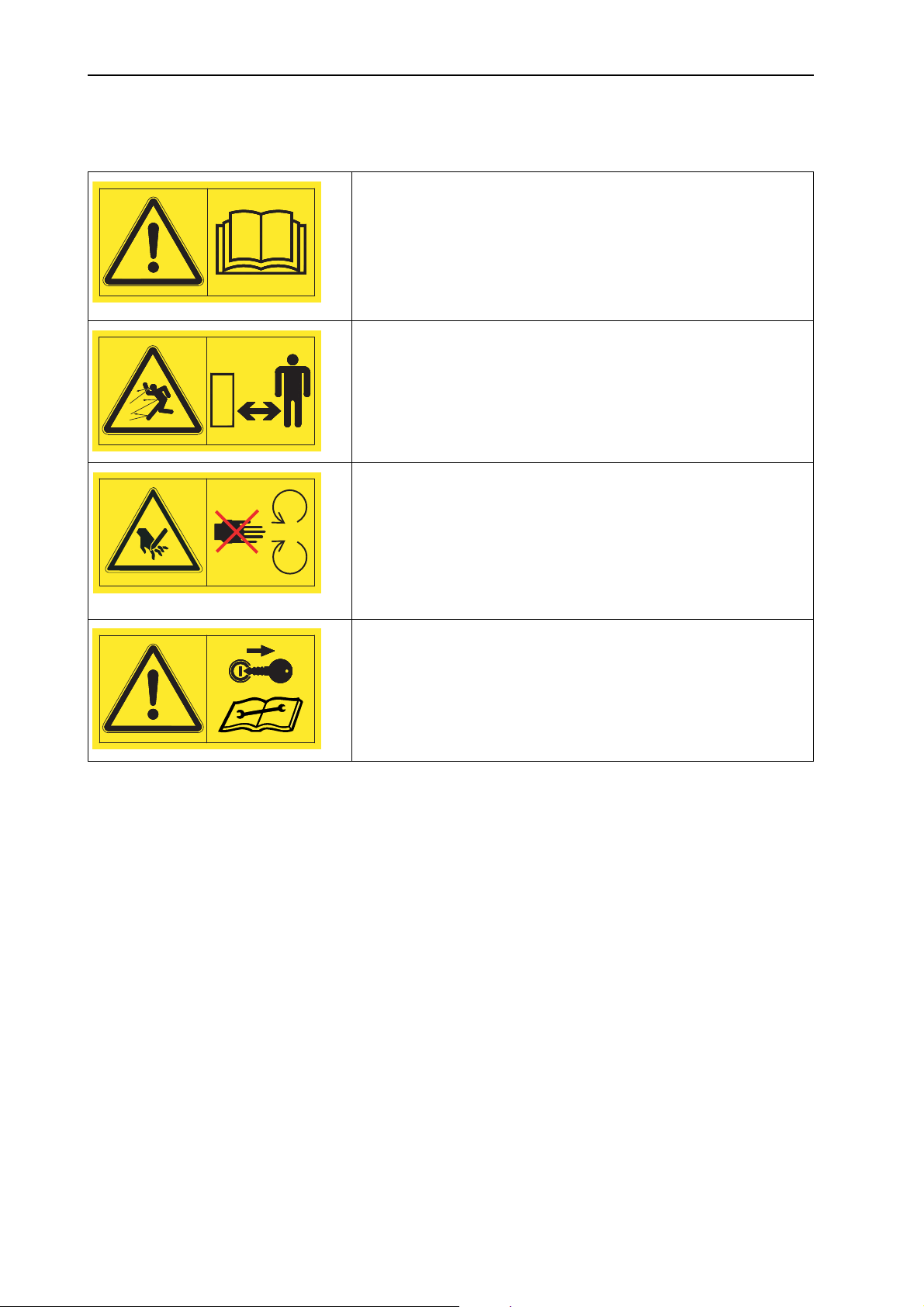
Safety 3
3.11.1 Warning stickers
Read the operator's manual and warnings.
Read and observe the operator's manual and warning messages before commissioning the machine.
The operator's manual explains in detail how to operate the
spreader and contains valuable information on operation,
care and maintenance.
Danger due to ejection of material.
Danger of injury to the whole body caused by ejected spreading material.
Before starting the spreading operation, instruct all people to
leave the hazard zone (spreading range) of the machine.
Danger due to moving parts.
Risk of body parts being cut off.
Reaching into the danger areas of the rotating spreading
disc, the agitator or the universal drive shaft is prohibited.
Switch off the tractor’s motor and remove the key before carrying out repair and adjustment work.
Remove the ignition key.
Before carrying out any repair and maintenance work, shut
off the engine and remove the ignition key. Disconnect the
power supply.
20
Page 29
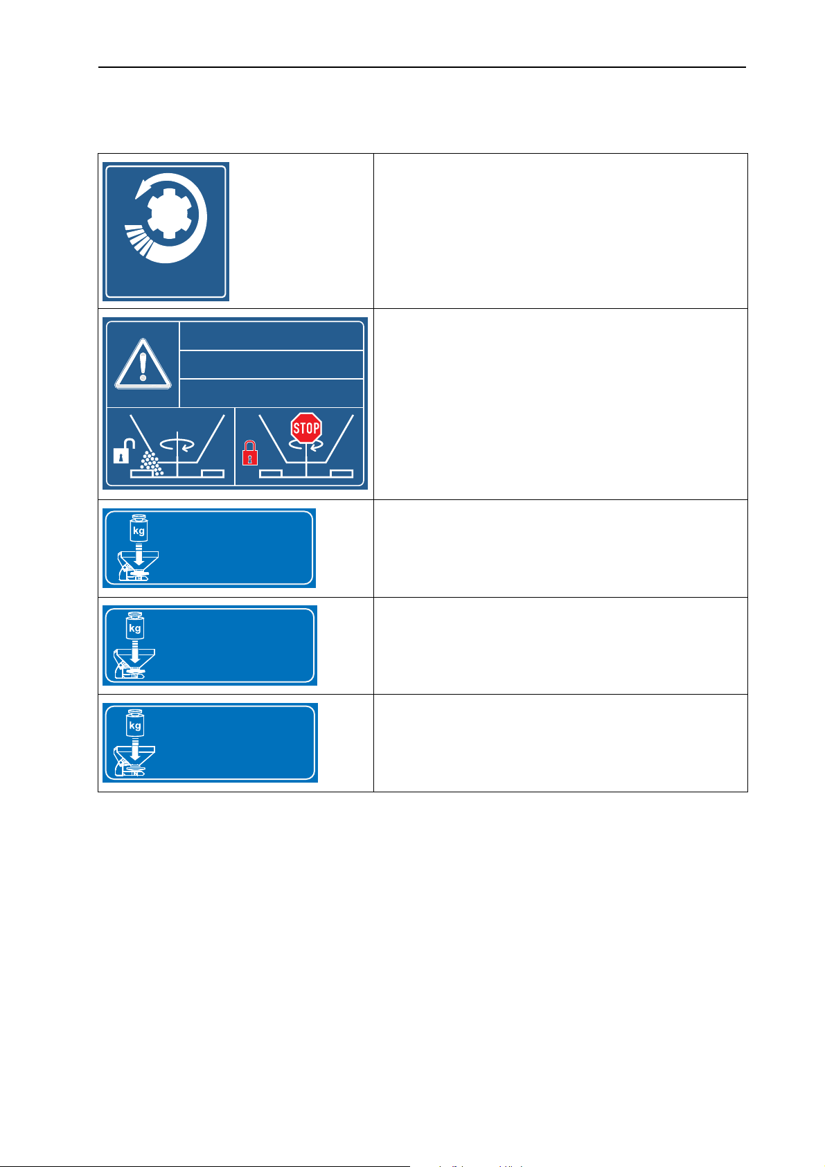
3.11.2 Instruction stickers and nameplate
2057022
Arrêter l'agitateur quand
les vannes sont fermées !
CAUTION!
Rührwerk bei geschlossenem
Schieber ausschalten!
ATTENTION!
Switch the agitator off
when the sliders are closed!
ACHTUNG!
800 kg
2053916
max.
PTO speed
540
min
2052291
-1
The rated speed of the PTO shaft is 540 rpm.
Agitator stop
If the metering slide is closed, the agitator is to be
stopped.
Safety
3
max.
1000 kg
max.
1800 kg
Maximum payload of 800 kg with the AXEO 2.1
Maximum payload of 1000 kg with the AXEO 6.1
2054101
Maximum payload of 1800 kg with the AXEO 18.1
2052258
21
Page 30
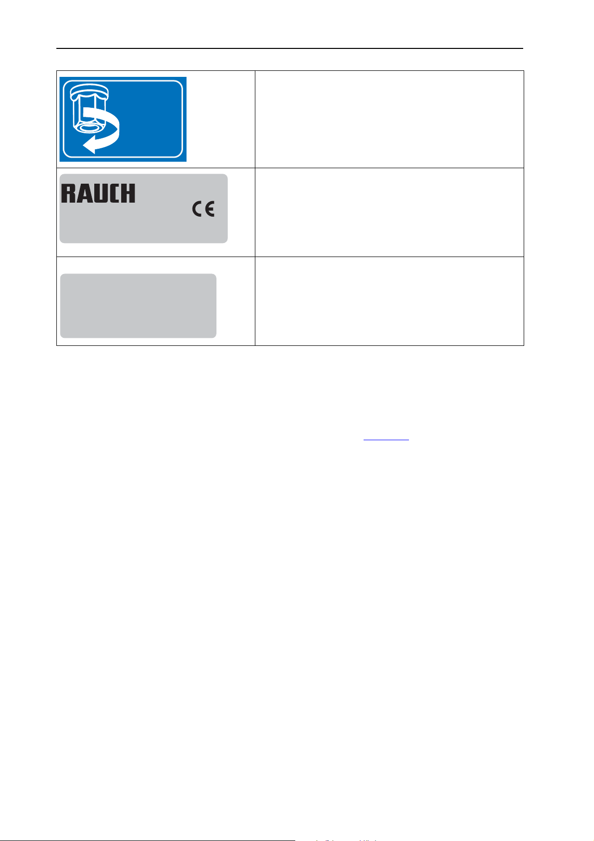
Safety 3
2056145
120 Nm
Landmaschinenfabrik GmbH
Landstraße 14
D-76547 Sinzheim
Typ:
Masse: Baujahr:kg
12345
Tightening torque of 120 Nm (hopper at frame)
Nameplate
Serial number
3.12 Lighting system with reflector and sidelights
The lighting equipment must be attached as specified and must always be in operating condition. Lights must not be covered or obscured by dirt.
Machine type AXEO 18.1 is factory-equipped with proper rear and side lighting
(for attachment to the machine, please refer to figure 3.2
and AXEO 2.1, the lighting system is available as a option.
). For types AXEO 6.1
22
Page 31

4 Technical data
4.1 Manufacturer
RAUCH Landmaschinenfabrik GmbH
Landstraße 14
D-76547 Sinzheim
Phone: +49 (0) 7221 / 985-0
Fax: +49 (0) 7221 / 985-200
Service Centre, Technical Customer Service
RAUCH Landmaschinenfabrik GmbH
Postfach 1162
D-76545 Sinzheim
Phone: +49 (0) 7221 / 985-250
Fax: +49 (0) 7221 / 985-203
Technical data
4
23
Page 32
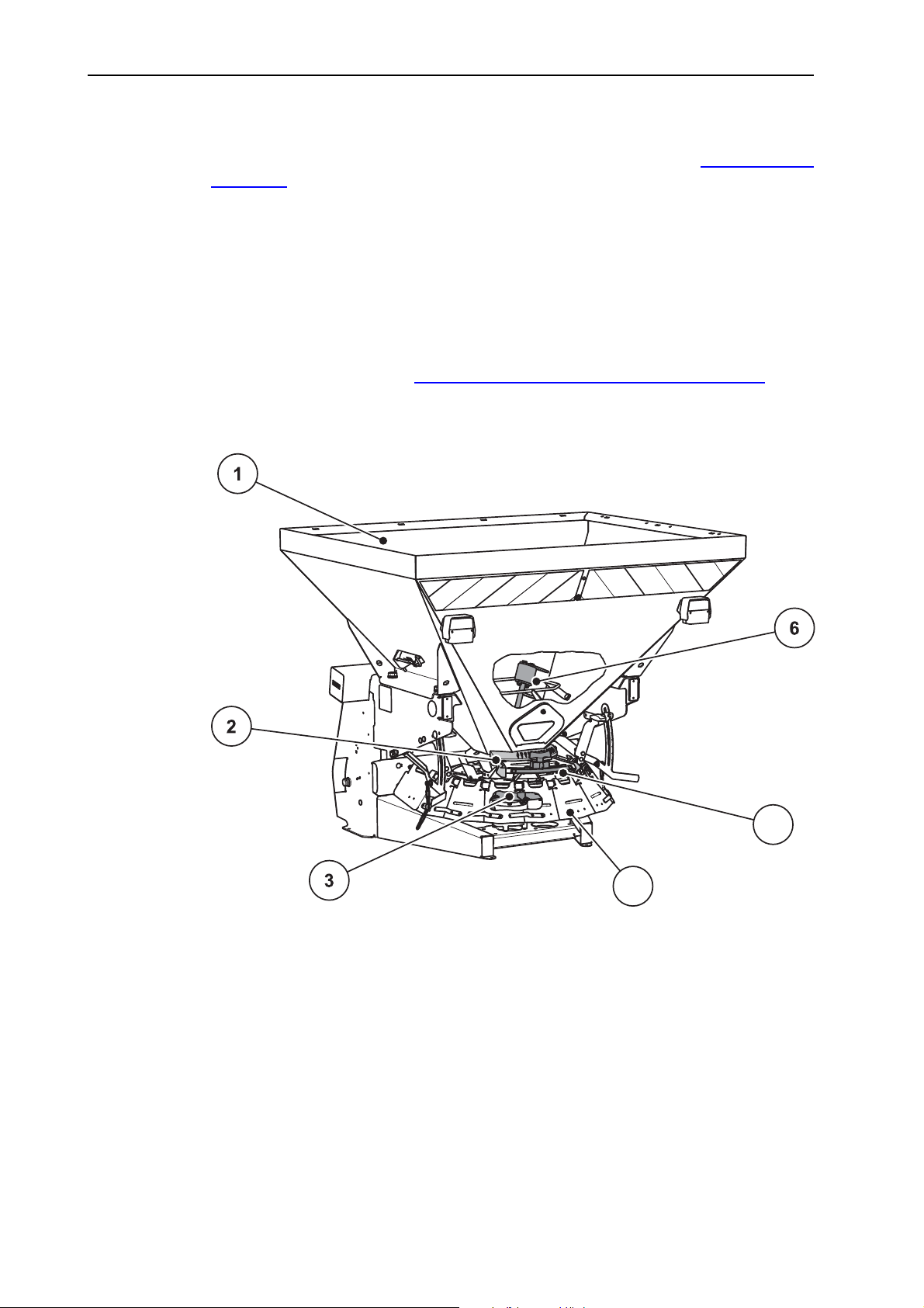
Technical data 4
5
4
4.2 Description of the machine
Use the machines of the AXEO series in accordance with chapter “Intended use“
on page 1.
The machine consists of the following assemblies.
Hopper with agitator and outlet
Frame and coupling points
Drive elements (universal drive shaft, transmission, hydraulic motor)
Metering elements (agitator, metering slide, scale for the spreading volume)
Elements for adjusting the working width
Safety equipment, see “Safety equipment at the machine“ on page 16.
4.2.1 Assembly overview, rear (all machine types)
24
Figure 4.1: Assembly overview - Rear
[1] Hopper
[2] Adjustment centre for drop point
[3] Spreading disc
[4] Spreading width limiter plates
[5] Application rate scale
[6] Agitator in hopper
Page 33
4.2.2 Assembly overview, front, PTO drive
Technical data
4
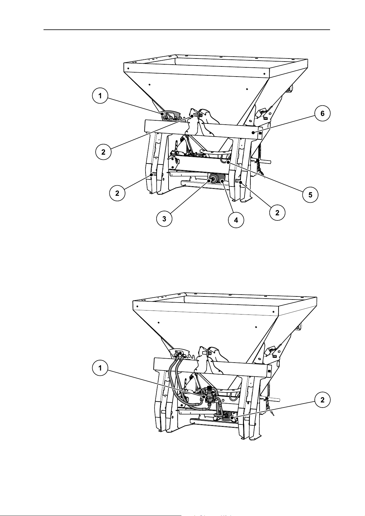
Figure 4.2: Assembly overview - Front
[1] Hose and cable tray
[2] Coupling points
[3] Transmission spigot
4.2.3 Assembly overview, front, hydraulic drive
[4] Transmission
[5] Drive shaft mounting bracket
[6] Frame
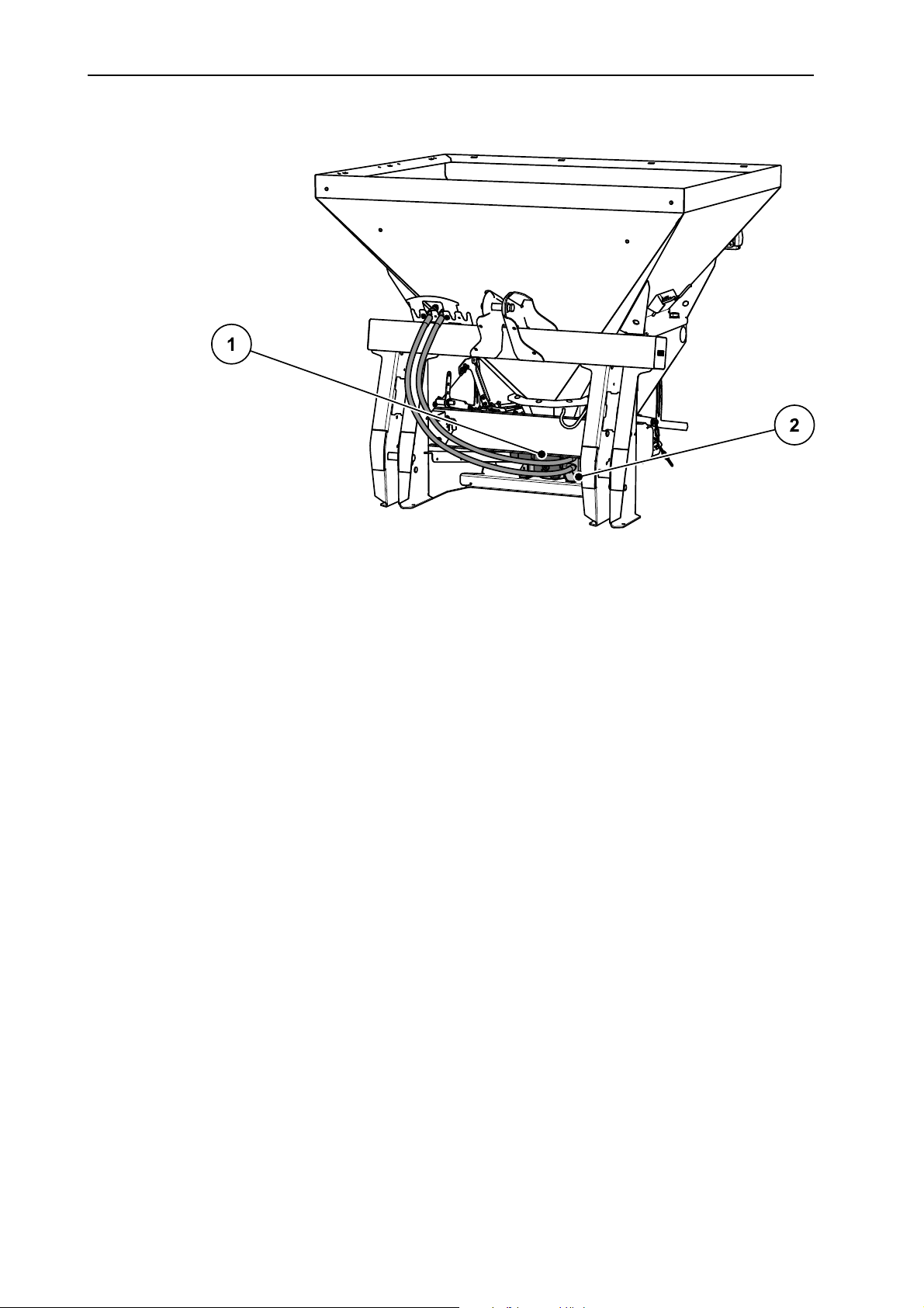
Figure 4.3: Assembly overview: Hydraulic drive
[1] Current regulation valve.
[2] Hydraulic motor
25
Page 34
Technical data 4
4.2.4 Assembly overview, HydroControl (-HC)
Figure 4.4: Assembly overview: HydroControl (-HC) example
[1] Hydraulic block
[2] Hydraulic motor
26
Page 35
Technical data
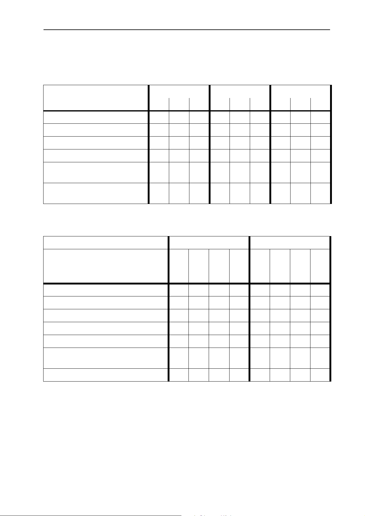
4.3 Versions
4.3.1 Drive with universal drive shaft
Type AXEO 2.1 AXEO 6.1 AXEO 18.1
Function / version H C Q H C Q H C Q
4
Hydraulic metering slide actuator
Electrical metering slide actuator
Electronic application rate control
Electronic speed control
Electrical spreading width limiter
(option)
Electronic spreading width limiter
(option)
4.3.2 Drive with hydraulic motor
Type AXEO 2.1 AXEO 6.1
Function / version
H-100
C-100
Q-100
H-100
Q-100-HC
C-100
Q-100
Q-100-HC
Hydraulic metering slide actuator
Electrical metering slide actuator
Electrical spreading width limiter
Electronic application rate control
Electronic speed control
Electrical spreading width limiter
(option)
Electronic spreading width limiter
(option)
27
Page 36
Technical data 4
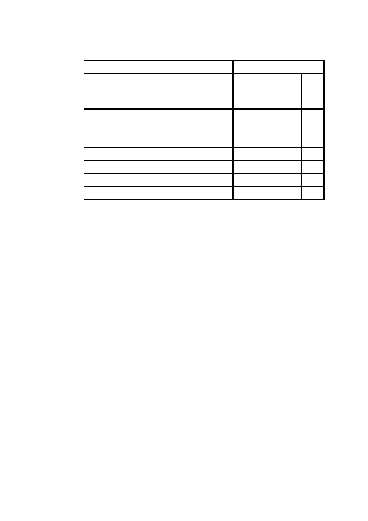
Type AXEO 18.1
Function / version
H-200
C-200
Q-200
Q-200-HC
Hydraulic metering slide actuator
Electrical metering slide actuator
Electrical spreading width limiter
Electronic application rate control
Electronic speed control
Electrical spreading width limiter (option)
Electronic spreading width limiter (option)
28
Page 37
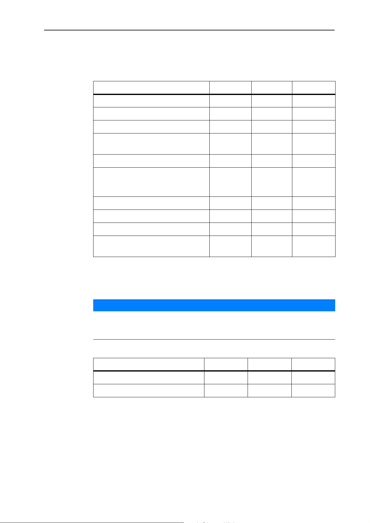
4.4 Technical data of basic equipment
Dimensions:
Data AXEO 2.1 AXEO 6.1 AXEO 18.1
Total width 100 cm 120 cm 150 cm
Overall length 87 cm 95 cm 121 cm
Filling level (basic machine) 96 cm 123 cm 128 cm
Technical data
4
Distance between centre of gravity
40 cm 40 cm 55 cm
and lower link coupling point
Filling width 88 cm 109 cm 139 cm
Working width (depending on
1 - 8 m 1 - 8 m 1 - 8 m
spreading material and spreading
disc type)
PTO speed max. 650 rpm 650 rpm 650 rpm
Hopper capacity 250 l 560 l 750 l
Hydraulic pressure max. 200 bar 200 bar 200 bar
Sound pressure level1 (measured in
75 dB(A) 75 dB(A) 75 dB(A)
the closed driver's cabin of the tractor)
1. Since the sound pressure level of the machine can only be determined while the tractor is running, the actual measured value substantially depends on the tractor used.
Weights and loads:
NOTICE
The empty weight (mass) of the machine varies depending on the feature package and attachment combination. The empty weight (mass) shown on the
nameplate refers to the standard version.
Data AXEO 2.1 AXEO 6.1 AXEO 18.1
Empty weight 130 kg 160 kg 230 kg
Payload max. 800 kg 1000 kg 1800 kg
29
Page 38
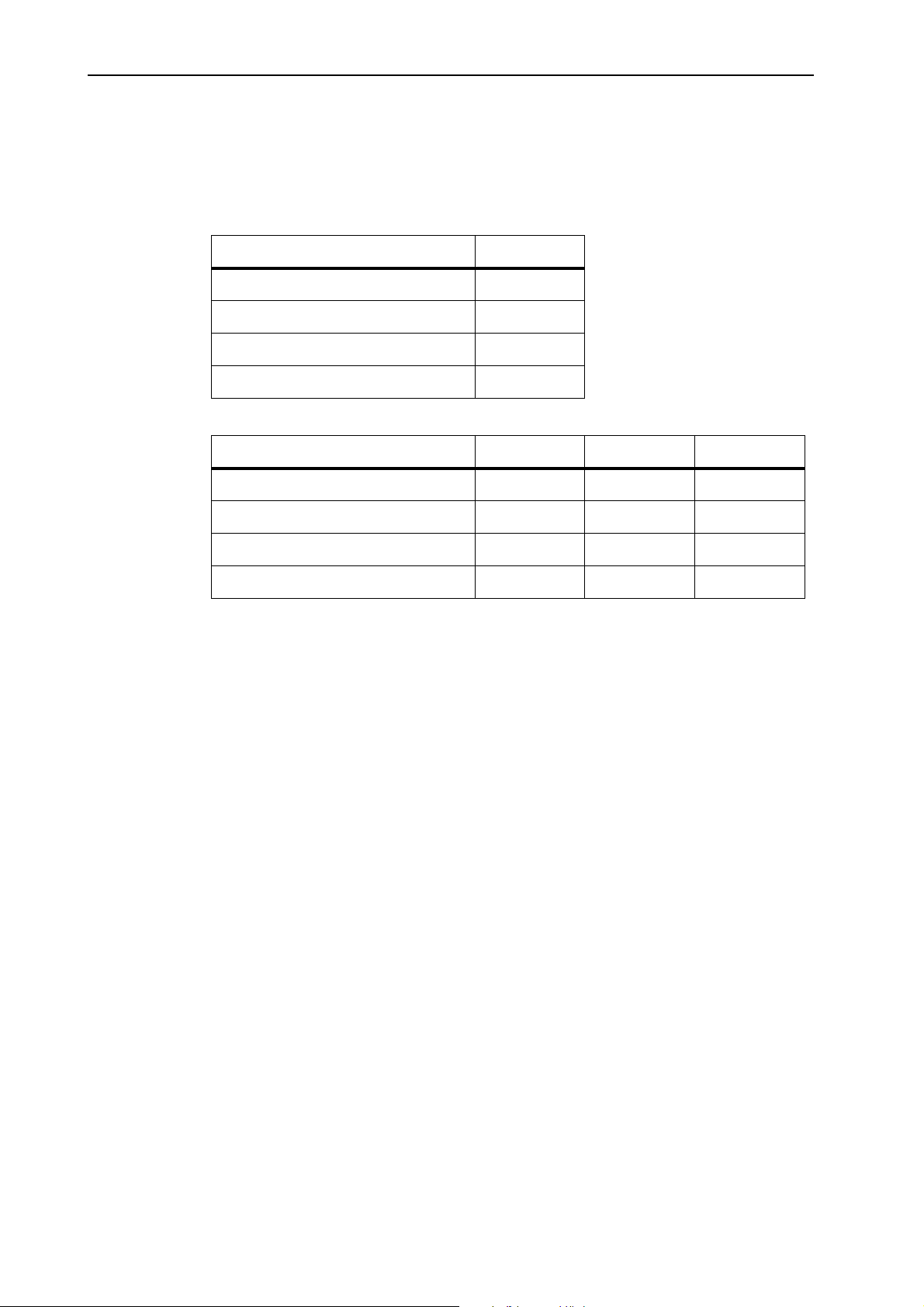
Technical data 4
4.5 Technical data of extensions and extension combinations
Machines of the AXEO series can be operated with different extensions and combinations of extensions. The capacity, dimensions and weights may change depending on the selected feature package.
Extension AXEO 2.1 AX 100
Change in capacity + 100 l
Change in filling height + 14 cm
Extension weight 14 kg
Description 4-sided
Extension AXEO 18.1 AX 250 AX 500 AX 750
Change in capacity + 250 l + 500 l + 750 l
Change in filling height + 15 cm + 29 cm + 44 cm
Extension weight 23 kg 35 kg 47 kg
Description 4-sided 4-sided 4-sided
30
Page 39

5 Transportation without tractor
5.1 General safety instructions
Read the following instructions before transporting the machine:
If no tractor is used, the machine may only be transported with an empty hopper.
The work may only be carried out by suitable, trained and expressly author-
ised personnel.
Suitable means of transportation and lifting equipment (e.g. crane, forklift
truck, lifting tackle ...) are to be used.
Determine the transportation route early, and remove possible obstacles.
Check that all safety and transportation devices are fully operational.
Secure all danger areas appropriately, even if they only exist briefly.
The person responsible for transportation ensures that the machine is trans-
ported appropriately.
Unauthorised persons are to be kept away from the transport route. The are-
as concerned must be cordoned off!
Transportation without tractor
5
Cautiously transport the machine and handle it with care.
Make sure that allowance is made for the centre of gravity. If necessary, ad-
just the lifting tackle so that the machine is correctly suspended.
Transport the machine to the final destination as close to the ground as pos-
sible.
5.2 Loading and unloading, parking
1. Determine the weight of the machine.
Details are provided on the nameplate.
If applicable, also take the weight of mounted special equipment into account.
2. Carefully lift the machine with suitable lifting equipment.
3. Carefully set the machine down on the loading platform of the transport vehi-
cle or on solid ground.
31
Page 40

Transportation without tractor 5
32
Page 41

6 Commissioning
6.1 Accepting the machine
When accepting the machine, please check the completeness of the scope of delivery.
The standard equipment includes
1 single-disc spreader of the AXEO series
1 operator's manual AXEO 2.1/6.1/18.1
1 upper link pin with lynch pin and securing chain
2 upper link pins with lynch pin and securing chain
1 adjustable spreading width limiter
1 spreading disc
1 universal drive shaft including operator's manual (model H, C, Q)
1 protective grid
Commissioning
6
Version Q or Q-100/200-HC: QUANTRON-K2 control unit
Version C: E-CLICK control unit
Please also check any special accessories that you may have ordered.
Check for any shipping damage or missing parts. Have transport damage confirmed by the transport company.
NOTICE
When receiving the machine, check that all attached components are correctly
and securely tightened.
In case of doubt, please contact your dealer or the factory directly.
33
Page 42

Commissioning 6
6.2 Requirements for the tractor
To ensure a safe and correct use of the machine, the tractor must meet the necessary mechanical, hydraulic, and electrical requirements.
Universal drive shaft connection: 1 3/8 inches, 6 splines, 540 rpm,
Version H: Oil supply: max. 200 bar, single-acting control valve
Operating voltage: 12 V
Three-point linkage category I for AXEO 2.1 and 6.1
Three-point linkage category II for AXEO 18.1
Version H-100/200:
- two (2) single-acting control valves
- 1 free return
- Oil supply: max. 200 bar
Version C-100/200, Q-100/200, Q 100-HC/200-HC:
- 1 single-acting control valve
- 1 free return
- Oil supply: max. 200 bar
34
Page 43

6.3 Mounting the universal drive shaft (versions H, Q, C)
Depending on the version, the machine can be equipped with a transmission as
drive for the spreading disc and agitator.
n CAUTION
Material damages due to unsuitable drive shaft
The machine is delivered with a drive shaft that is designed according
to the device and performance.
The use of incorrectly dimensioned or inadmissible drive shafts, for
instance without guard or suspension chain, may cause personal
injury or lead to damage to the tractor and/or the machine.
Use universal drive shafts approved by the manufacturer only.
Follow the directions in the operator’s manual of the universal
drive shaft manufacturer.
Depending on the version, the machine may be equipped with different universal
drive shafts:
Commissioning
6
Universal drive shaft with full protection
Universal drive shaft with ratchet clutch and full protection Refer to
11.9: Universal drive shaft with ratchet clutch, page 116
6.3.1 Checking the length of the universal drive shaft
Check the length of the universal drive shaft during its first assembly to the
tractor.
Universal drive shaft tubes that are too long can result in damage to the
universal drive shaft and the machine.
NOTICE
Observe the installation and shortening instructions provided in the operator's
manual of the drive shaft manufacturer when checking and adjusting the drive
shaft. The operator's manual is attached to the drive shaft on delivery.
.
35
Page 44
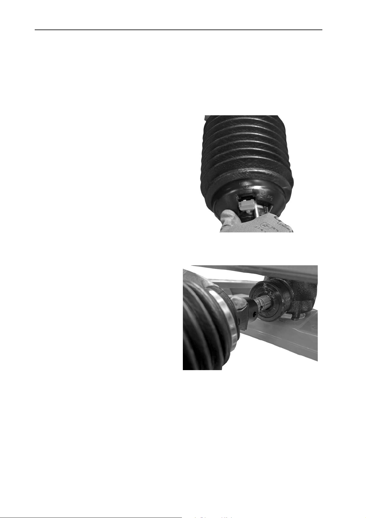
Commissioning 6
6.3.2 Fitting / removing the universal drive shaft
Fitting:
1. Check the installation position.
The drive shaft end that is marked with a tractor symbol must point to the
tractor.
2. Pull lubrication nipple at universal drive shaft guard.
3. Rotate the plastic ring with
bayonet lock of the universal
drive shaft guard by means
of a screw driver.
4. Open the universal drive
shaft guard backwards.
5. Hold the universal drive shaft
guard and the clamp in an
open position with your hand.
6. Grease the transmission
spigot. Mount the transmission spigot at the drive shaft.
Figure 6.1: Open the universal drive shaft
guard
Figure 6.2: Push the universal drive shaft
onto the transmission spigot
36
Page 45
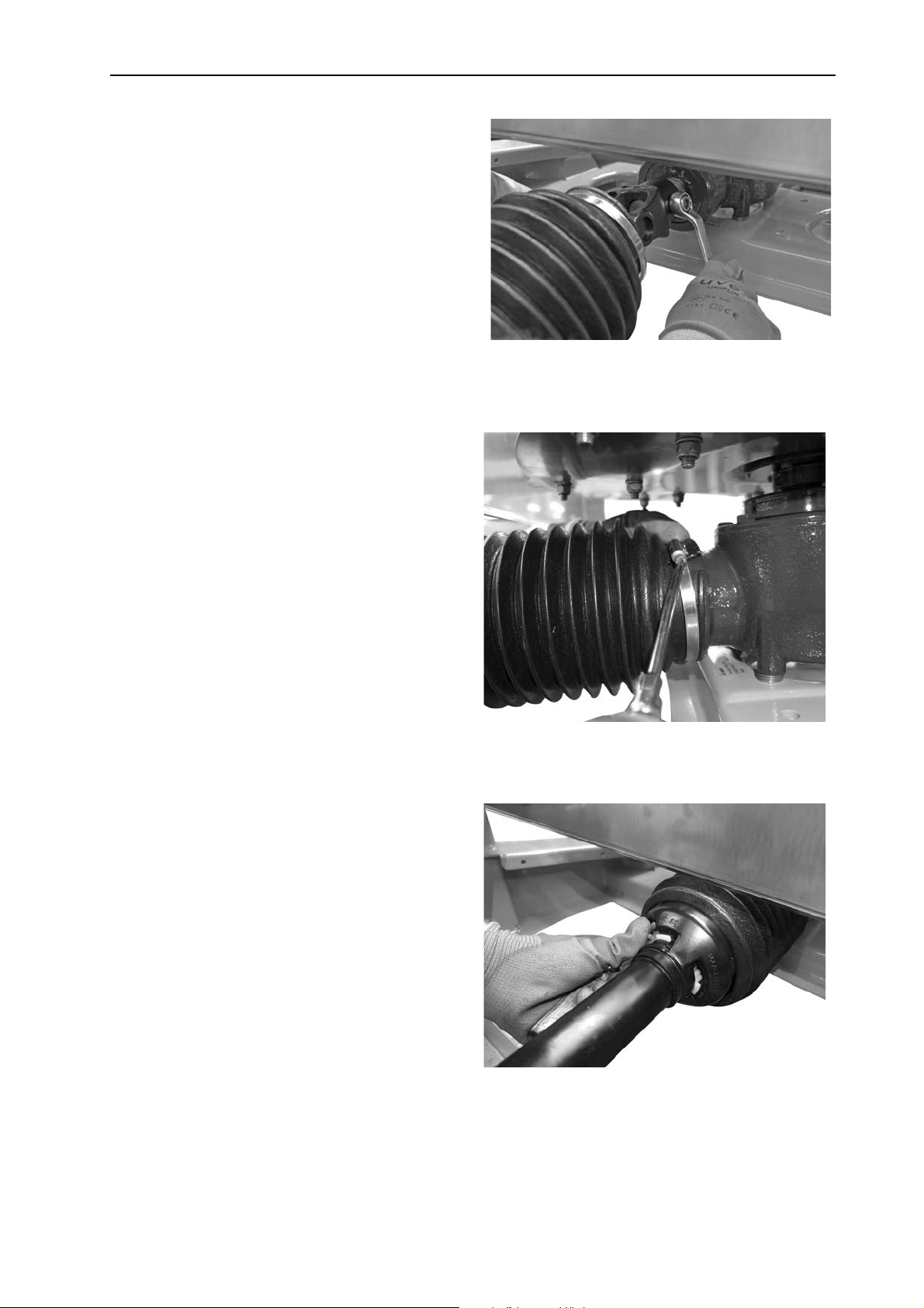
7. Tighten the hex cap screw
and nut using a size 17
wrench (max. 35 Nm).
Commissioning
Figure 6.3: Connect the universal drive
shaft
6
8. Push the universal drive
shaft guard with hose clamp
over the universal drive shaft
and attach it to the transmission neck.
9. Tighten the hose clamp.
10. Rotate the plastic ring until it
reaches its locking position.
11. Press the lubrication nipple
at the universal drive shaft
guard into a closed position.
Figure 6.4: Mount the universal drive shaft
guard
Figure 6.5: Secure the universal drive shaft
guard
37
Page 46
Commissioning 6
Instructions for dismounting:
Dismount the universal drive shaft in reverse order of mounting.
Do not use the suspension chain for suspending the universal drive shaft.
Always store the uncoupled universal drive shaft on the bracket provided.
- See chapter 4.2: Description of the machine, page 24
Figure 6.6: Storage of cables and hydraulic hoses
[1] Bracket for hoses and cables
.
1
38
Page 47
6.4 Installing the machine on the tractor
6.4.1 Preconditions
n DANGER
Danger to life due to unsuitable tractor
Using an unsuitable tractor for the machine may result in severe
accidents during operation or road travel.
Only use tractors that comply with the technical require-
ments of the machine.
Use the vehicle's documentation to chec
uitable for the machine.
s
Check the following specific requirements:
Are both the tractor and the machine in a reliable condition?
Does the tractor comply with the mechanical, hydraulic, and electrical require-
ments (see “Requirements for the tractor“ on page 34)?
Commissioning
k if your tractor is
6
Do the mounting categories of the tractor and the spreader match (if neces-
sary, consult your dealer)?
Is the machine securely positioned on level and solid ground?
Do the axle loads conform to the stipulated calculations
(see “Axle load calculation“ on page 119)?
6.4.2 Attaching the machine
Danger to life due to inattention or faulty operation.
There is a crushing hazard that may result in fatal injury for persons standing between the tractor and the machine when the tractor approaches or the hydraulic system is actuated.
The tractor may brake too late or not at all because of inattention
or faulty operation.
n DANGER
Ensure that nobody is present in the hazard zone betwe
the
tractor and the machine.
en
n DANGER
Risk of tipping or falling
There are no anchor or lifting points provided on the attachments
or the frame of the machine.
If the machine is lifted or moved on the attachments or the frame,
it may tip over or fall. This poses a danger to life for the persons
involved.
Fasten the machine to a pallet.
39
Page 48

Commissioning 6
The machine is installed at the three-point linkage (rear power lift) of the tractor.
Installation instructions:
The AXEO 2.1/6.1 is only to be connected to a category II tractor with cate-
gory I clearance and using reducing sleeves.
AXEO 18.1 is only to be connected to a category III tractor with category II
clearance and using reducing sleeves.
AXEO 2.1 is only to be connected to a category 1N tractor using an adapter.
- The maximum payload is reduced to 300 kg.
The lower and upper link pins must be secured with lynch pins or spring clips.
Always install the machine horizontally.
To ensure correct cross-distribution of the spreading material, the machine
must be mounted as specified in the fertiliser chart.
In order to avoid sideways movements during spreading, make sure that the
machine does not have too much sideways play.
- The lower link arms of the tractor are to be braced by means of stabilising
struts or chains.
NOTICE
We recommend using lower link hooks with a hydraulic upper link for safety and
comfort.
40
Page 49
Commissioning
B
A
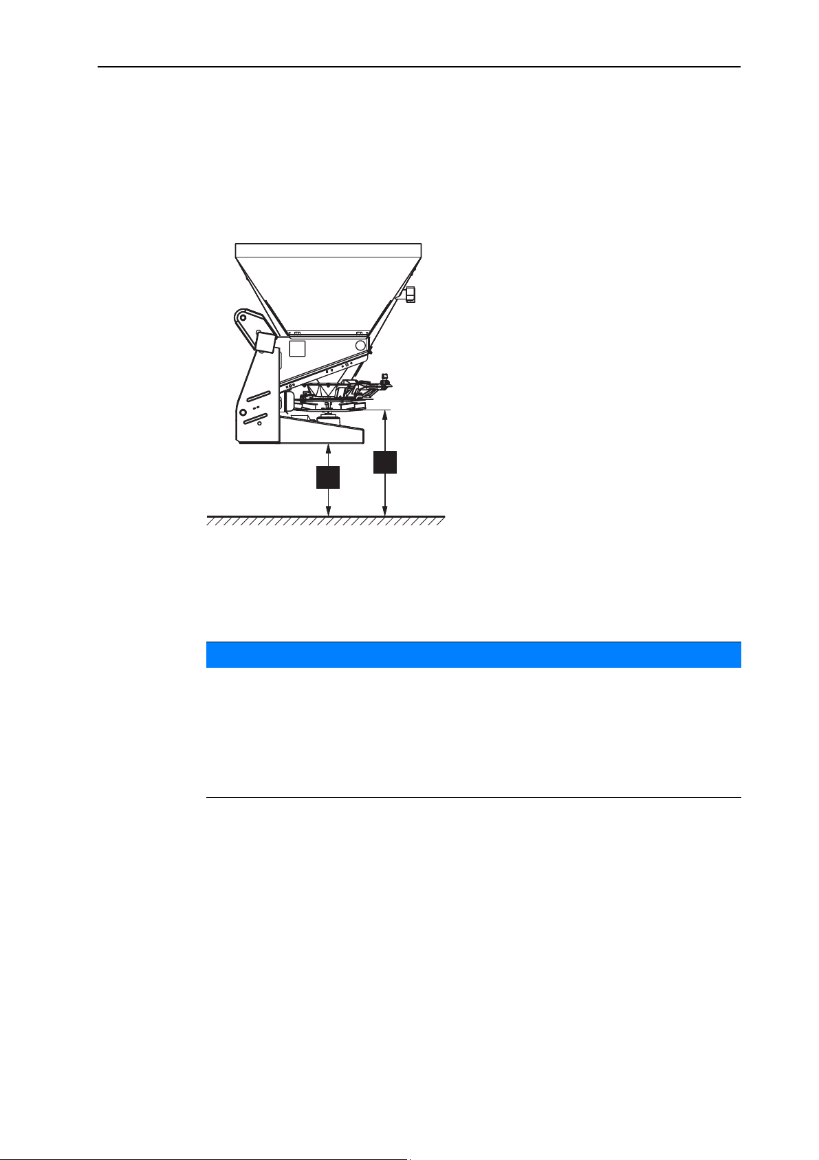
Definition of mounting height
The information on the mounting height refers to the distance between the lower
edge of the spreading disc and the ground with a horizontally mounted machine.
The mounting height (dimension A) is 55 cm.
Measure the distance between the lower edge of the frame and the ground.
- A clearance of 33 cm is required (dimension B).
6
Figure 6.7: Setting the mounting height
[A] = 55 cm
[B] = 33 cm
NOTICE
Maximum mounting height
In order to prevent accidental contact with the spreading disc, the distance between the lower edge of the frame and the ground must not exceed 120 cm (dimension B).
This corresponds to a maximum admissible mounting height of the machine of
142 cm (dimension A).
1. Start the tractor.
The PTO shaft is switched off.
2. Move the tractor to the machine.
Do not latch the lower link hooks into place yet.
Make sure there is enough space between the tractor and the machine in
order to be able to connect the drives and control elements.
3. Switch off the tractor engine. Remove the ignition key.
4. Pull the hand brake of the tractor.
5. Mount the drive shaft to the tractor.
6.
Connect the electrical and hydraulic metering slide actuators and the lightning.
41
Page 50
Commissioning 6
7.
From the tractor cab, connect the lower link hooks and the upper link to the designated coupling points, as described in the operator's manual of your tractor.
NOTICE
We recommend using lower link hooks with a hydraulic upper link for safety and
comfort.
8. Check the tight seat of the machine.
9. Carefully raise the machine to the desired lifting height.
n CAUTION
Material damages due to excessively long drive shaft
When the machine is lifted up, the universal drive shaft halves can
come into contact inside each other. This can cause damage to the
drive shaft, the transmission or the machine.
Check the clearance between the machine and the tractor.
Make sure there is enough space (at least 20 to 30mm)
between the outer pipe of the drive shaft and the protective
cone on the spreader side.
10. Shorten the universal drive shaft, if required.
NOTICE
Have the universal drive shaft shortened by your dealer or your expert workshop
only.
NOTICE
Observe the installation and shortening instructions provided in the operator’s
manual of the drive shaft manufacturer when checking and adjusting the
drive shaft. The operator's manual is attached to the drive shaft on delivery.
42
Page 51
Commissioning
6.5 Connecting the hydraulic drive (Version H-100/200, Q-100/200, C-100/200, Q-100/200-HC)
Depending on the model, the AXEO single-disc spreader may be equipped with
a hydraulic motor as drive for the spreading disc and the agitator.
A single-acting control valve and a free return flow are needed on the tractor. In
addition, a non-return valve is fitted in the return line.
The hydraulic drive is connected to the tractor via 2 hydraulic hoses.
NOTICE
Connect the connector with the red protection cap to the pressure line.
Connect the connector with the blue protection cap to the return line.
Uncoupled hydraulic hoses must not get into contact with the ground.
Always put a dust cap on the uncoupled hydraulic hoses.
Secure the uncoupled hydraulic hoses only at the bracket provided for hoses
and cables. Refer to figure 3.5
.
6
Adjusting the hydraulic drive (H-100/200, Q-100/200, C-100/200)
The single-disc spreader is driven by a hydraulic motor with a displacement of
100 cm³ or 200 cm³.
Adjust the agitator speed to your spreading material as specified in the fertil-
iser chart.
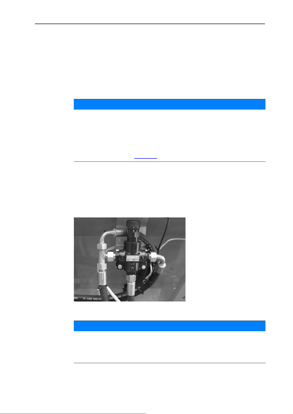
Set the agitator speed at the hand wheel of the flow control valve.
Figure 6.8: Flow control valve
NOTICE
Spreading disc and agitator drive for machines with HydroControl (model Q100/200-HC) is realised automatically at the QUANTRON-K2 control unit.
The HydroControl function is described in a separate operator's manual for the
QUANTRON-K2 control unit.
43
Page 52

Commissioning 6
6.6 Connecting the metering slide actuator
6.6.1 Connecting the hydraulic metering slide actuator (Version H)
The AXEO single-disc spreader uses an single-acting hydraulic cylinder with return spring: Oil pressure closes, spring force opens
The hydraulic metering slide actuator is connected to the tractor via one hydraulic
hose.
A single-acting control valve is required at the tractor.
Instructions on connection of the hydraulic metering slide actuator
n WARNING
Risk of crushing and shearing in the area of the application
rate adjustment unit
When untightening the setscrew of the application rate limit stop,
the slide lever may move unexpectedly against the end of the
guide slot and cause severe injuries to the fingers.
Only untighten the setscrew of the application rate limit stop
if the metering slide is closed.
Do not place fingers in the guide slot of the application rate
adjustment unit.
If the machine is parked on its own (without tractor), fully
open the metering slide. Hydraulic cylinder at limit stop,
return spring still tensioned.
Attachment
1. Depressurise the hydraulic system.
2. Remove the hoses from the brackets attached to the frame of the machine.
3. Insert the hoses into the corresponding couplings on the tractor.
Secure the uncoupled hydraulic hoses only at the bracket provided for hoses
and cables. Refer to figure 3.5
Always put a dust cap on the uncoupled hydraulic hoses.
Uncoupled hydraulic hoses must not get into contact with the ground.
Before uncoupling, fully open the metering slide (see chapter 6.10: Parking
.
and unhitching the machine, page 47).
6.6.2 Connecting the electronic metering slide actuator: AXEO, Version Q
44
NOTICE
The machine version Q is equipped with an electronic metering slide actuator.
The electronic metering slide actuator is described in a separate operator's
manual for the QUANTRON-K2 control unit. This operator's manual is supplied
with the QUANTRON-K2 control unit.
Page 53
Commissioning
6.6.3 Connecting the electrical metering slide actuator: Version C
NOTICE
The machine version C is equipped with an electronic metering slide actuator
and spreading width limiter.
The electrical metering slide actuator is described in a separate operator's manual for the E-CLICK for Winter Service control unit. This operator's manual is
an integral part of the control unit.
6.7 Connecting the actuator for the spreading width limiter (Version H)
Depending on the version, the machine is equipped with an actuator for electrical
spreading width adjustment.
Connection
6
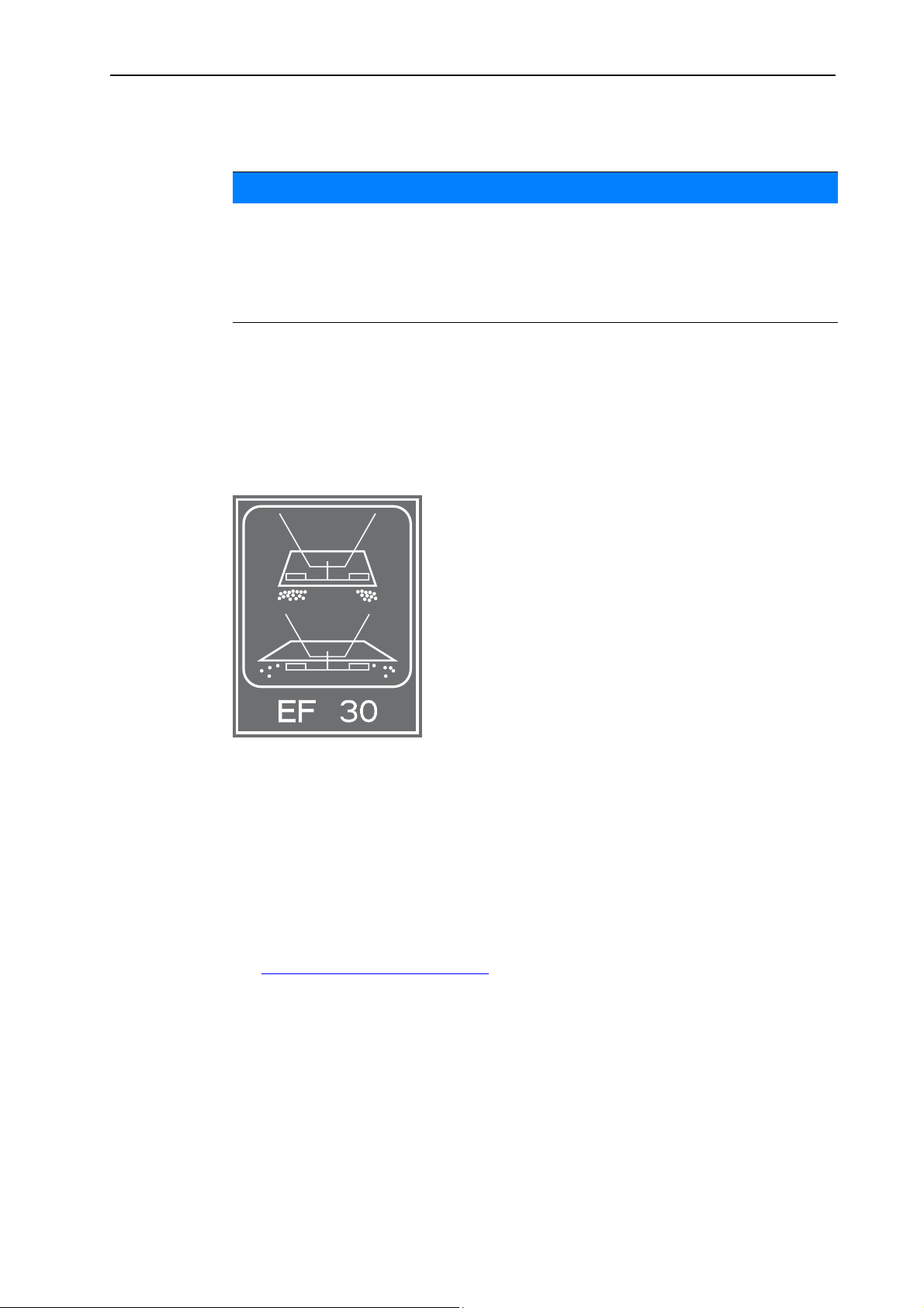
Figure 6.9: Marking of the spreading width limiter control units
Connect the actuator connector to the control unit.
6.8 Connecting the lighting
Lighting system:
Mounted at the single-disc spreader AXEO 18.1 as a standard.
Optionally available for the single-disc spreader AXEO 2.1/6.1. Refer to
“BLO 18 lighting“ on page 116
Connect the lighting via 7-pin connector to the tractor.
2056119
RAUCH
.
45
Page 54
Commissioning 6
6.9 Filling the machine
n DANGER
Danger of injury due to running engine
Working on the machine while the motor is running may result in
serious injury caused by mechanical components and escaping
spreading material.
Never fill the machine while the tractor motor is running.
Switch off the tractor engine.
Remove the ignition key.
Send third persons out of the danger area. Refer to “Hazard
zone“ on page 10.
n CAUTION
Inadmissible overall weight
If the permissible total weight is exceeded, this will affect the operating and road safety of the vehicle (machine and tractor) and may
cause serious damage to the machine and the environment.
Before you start filling, calculate the amount you can load.
Comply with the permissible overall weight.
Instructions on filling the machine
Close the metering slide.
Only fill the machine when it is attached to the tractor. Make sure that the
tractor is standing on level and solid ground.
When determining the maximum admissible loading amount, consider the
specific weight of the spreading material (kg/l).
- The weight of the spreading material depends on the type of spreading
material (e. g. grit, sand, fertiliser) and its state (dry, wet).
- see chapter 13: Axle load calculation, page 119
Secure the tractor against rolling away. Apply the handbrake.
Use suitable auxiliary equipment for filling: e.g. front-end loader, auger, silo.
When manually filling it (e.g. loading it with big bags), use suitable steps.
46
Fill the machine up to the edge maximally.
Page 55
6.10 Parking and unhitching the machine
You can securely place the machine onto the frame.
n DANGER
Crushing hazard between the tractor and the machine
Persons standing between the tractor and the machine while they
are being parked or unhitched are in lethal danger.
Ensure that nobody is present in the hazard zone between
the tractor and the machine.
Requirements for parking the machine:
Only park the machine on even and firm ground.
Only park the machine when the hopper is empty.
Relieve the load on the coupling points (lower/upper link) before removing the
machine.
Commissioning
6
After unhitching, place the universal drive shaft, hydraulic hoses, and electric
cables in the retainers provided for the purpose.
Instructions on hydraulic metering slide actuator
Please observe the following instructions on switching off the machine equipped
with hydraulic metering slide actuator.
n WARNING
Risk of crushing and shearing in the area of the application
rate adjustment unit
When untightening the setscrew of the application rate limit stop,
the slide lever may move unexpectedly against the end of the
guide slot and cause severe injuries to the fingers.
Only untighten the setscrew of the application rate limit stop
if the metering slide is closed.
Do not place fingers in the guide slot of the application rate
adjustment unit.
If the machine is parked on its own (without tractor), fully
open the metering slide. Hydraulic cylinder at limit stop,
return spring still tensioned.
47
Page 56
Commissioning 6
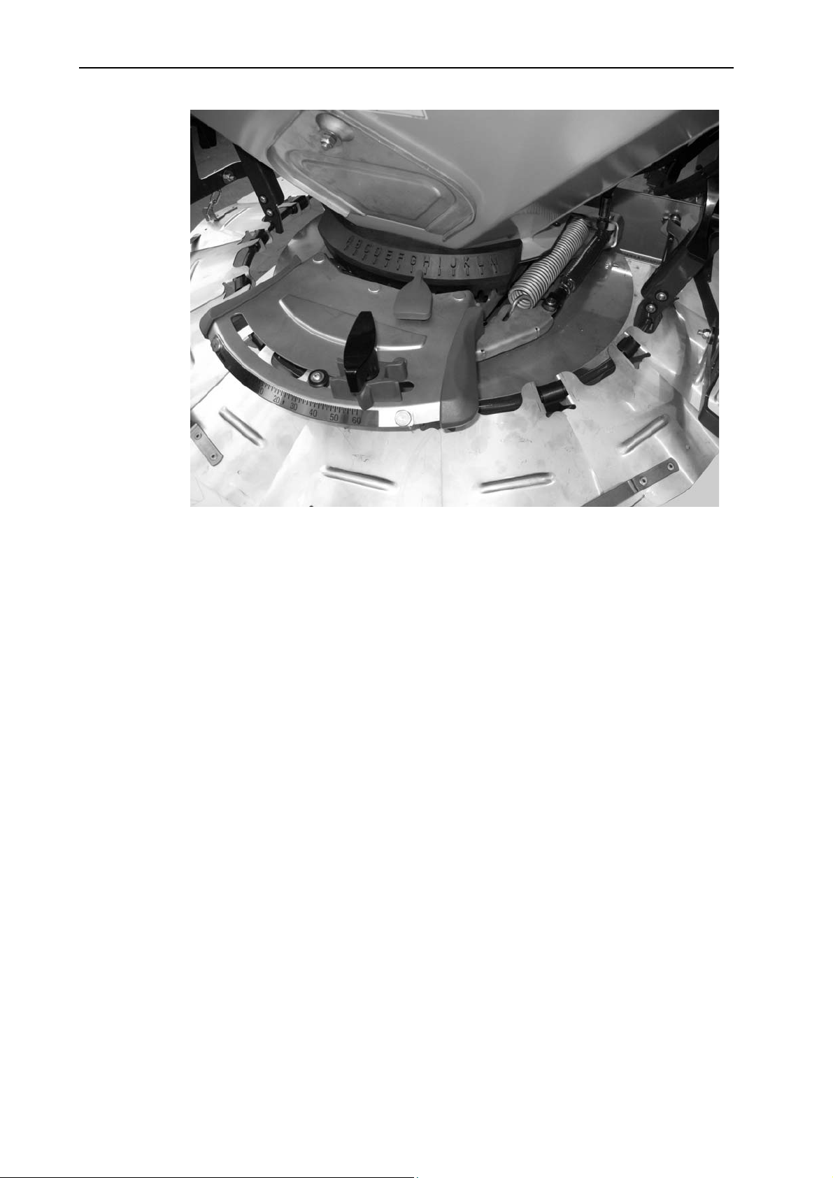
Figure 6.10: Metering slide open, hydraulic cylinder at limit stop
Opening the metering slide:
1. Fully close the metering slide at the control valve
2. Set the adjustment rate limit stop to maximum.
3. Fully open the metering slide at the control valve
Hydraulic cylinder is at limit stop.
The return spring is still tensioned.
48
Page 57
7 Machine settings
2
10
11
Danger from running motor
Setting the machine while the motor is running may result in serious injuries caused by mechanical components and escaping
spreading material.
Wait until all rotating parts have come to a complete stop
before making any adjustments.
Switch off the tractor engine.
Remove the ignition key.
7.1 Setting options overview
n DANGER
Machine settings
7
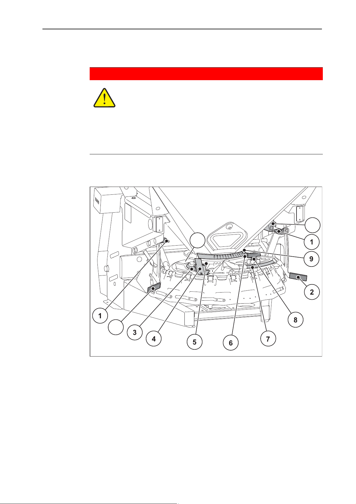
Figure 7.1: Adjustment elements at AXEO
[1] Adjustment screw for mechanical
spreading width limitation
[2] Spreading width limiter adjustment le-
ver
[3] Numeric scale for adjustment of the
half-side slide
[4] Half-side slide
[5] Half-side slide setscrew
[6] Drop point indication/setting
[7] Numeric scale for adjustment of the
application rate
[8] Setscrew with indicator element for
setting the application rate
[9] Alphabetic scale for drop point adjust-
ment
[10] Actuator (only with electrical spreading
width limiter)
[11] Spreading vanes of the spreading disc
49
Page 58
Machine settings 7
The machine spreading parameters are set at the adjustment elements.
Parameters Meaning Description
Spreading
quantity
Spreading pattern
position
Spreading width
Adjustment of the application rate by metering
Page 53
slide opening adjustment
Working width and spreading pattern adjustment by:
Drop point adjustment Page 55
Spreading width limiter adjustment Page 57
Half-side slide adjustment
Spreading vane adjustment Page 61
Spreading width adjustment in a range of ap-
Page 57
prox. 1 - 8 m (depending on spreading material).
50
Page 59
7.2 Spreading disc and agitator speed adjustment
7.2.1 PTO drive
For the speed to be set at the spreading disc or the agitator, please refer to the
fertiliser chart
NOTICE
If drop point adjustment is not sufficient for setting a symmetric spreading pattern, adjust the vanes on the spreading disc. Refer to 7.8: Setting the spreading
vanes, page 61.
NOTICE
With smaller working widths and good spreading material quality, the agitator
speed can be reduced.
Machine settings
7
7.2.2 Drive with hydraulic motor (Version H-100/200, Q-100/200, C-100/200)
At machines with hydraulic drive, the speed is set at the flow control valve. For
the values to be set, refer to the following table.
NOTICE
If drop point adjustment is not sufficient for setting a symmetric spreading pattern, adjust the vanes on the spreading disc. Refer to 7.8: Setting the spreading
vanes, page 61.
n CAUTION
Possible spreading errors and property damage
Incorrectly set spreading disc or agitator speed may lead to
increased wear or spreading errors.
For the speed to be set for the respective spreading mate-
rial, please refer to the fertiliser chart.
51
Page 60

Machine settings 7
Setting values for 100 cm3 hydraulic motor
Position of the hand
Speed in rpm Spreading material
wheel at the flow
control valve
365
3.5 110
4160
4.5 200 Grit
5 250 Salt and sand
6 325 Fertiliser
7 390 Fertiliser
8 445 Fertiliser
9510
10 570
Setting values for 200 cm
3
hydraulic motor
Position of the hand
Speed in rpm Spreading material
wheel at the flow control valve
330
475
5 120
6 155
7 195 Grit
8 225 Salt and sand
9 250
10 290
NOTICE
With smaller working widths and good spreading material quality, the agitator
speed can be reduced.
52
Page 61
7.3 Adjusting the application rate
The Q winter spreader is fitted with an electronic metering slide actuator for setting the application rate.
The electronic metering slide actuator is described in a separate operator's manual for the QUANTRON-K2 control unit. This operator's manual is supplied with
the QUANTRON-K2 control unit.
Risk of crushing and shearing in the area of the spreading
quantity adjustment!
When untightening the setscrew of the application rate limit stop,
the slide lever may move unexpectedly against the end of the
guide slot and cause severe injuries to the fingers.
NOTICE
n WARNING
Machine settings
7
Only untighten the setscrew of the application rate limit stop
if the metering slide is closed.
Do not place fingers in the guide slot of the application rate
adjustment unit.
If the machine is parked on its own (without tractor), fully
open the metering slide. Hydraulic cylinder at limit stop,
return spring still tensioned.
You can set the application rate via the metering slide opening at the numeric
scale on the scale plate.
For this purpose, move the pointer to the position specified beforehand in the fertiliser chart or from a calibration test. This is the Open stop position the slide is
hydraulically or electrically positioned at (depending on the version).
Adjusting in the direction of higher values opens the metering slider.
Adjusting in the direction of lower values closes the metering slider.
n CAUTION
Material damage caused by an insufficient metering slide
opening
Insufficient opening of the metering slide can cause blockages and
can damage the spreading material. Agitator wear increases.
Always select an adequate opening for the metering slide,
at which the spreading material flows out in an unobstructed
manner.
53
Page 62
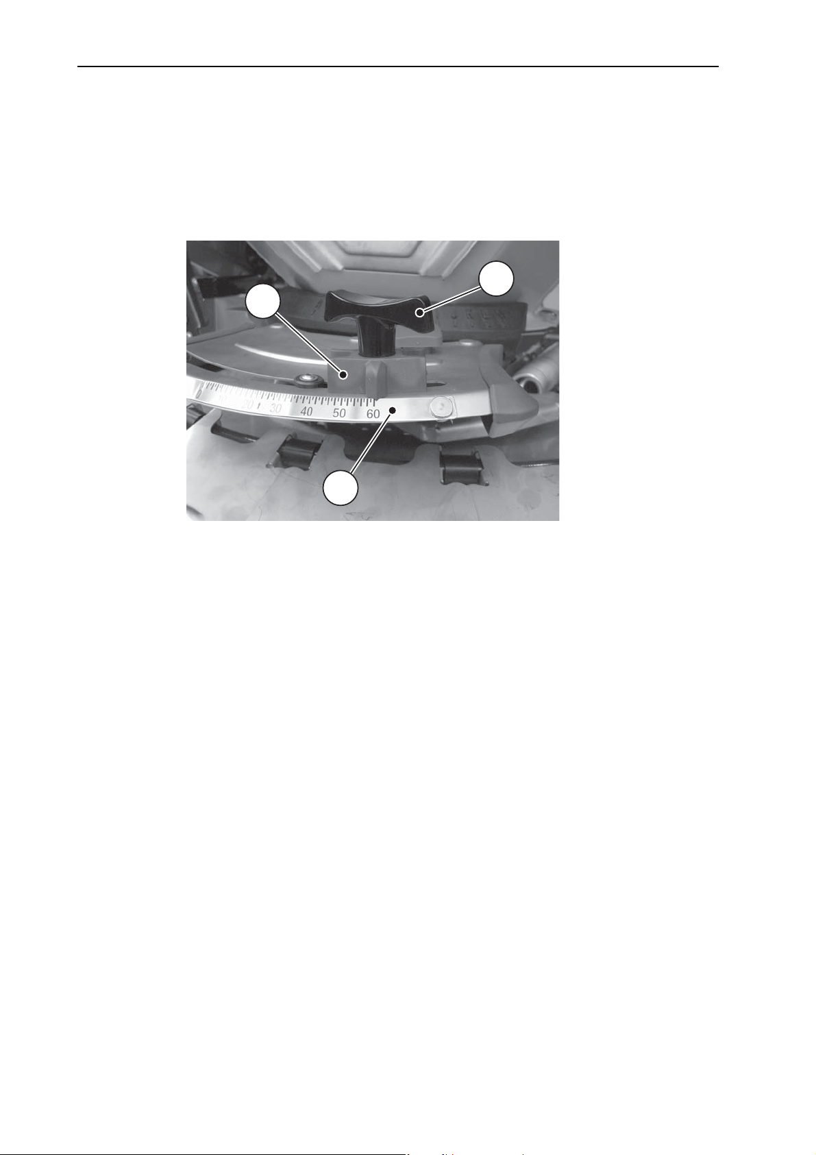
Machine settings 7
1
2
3
1. Close the metering slide completely.
2. Determine the position for the scale setting in the fertiliser chart or based on
the calibration test.
3. Untighten setscrew [2] at the stop.
4. Move the pointer [1] of the stop to the determined position.
5. Tighten the setscrew.
Figure 7.2: Scale for adjustment of the application rate
[1] Stop pointer
[2] Setscrew
[3] Numeric scale of the scale plate
54
Page 63
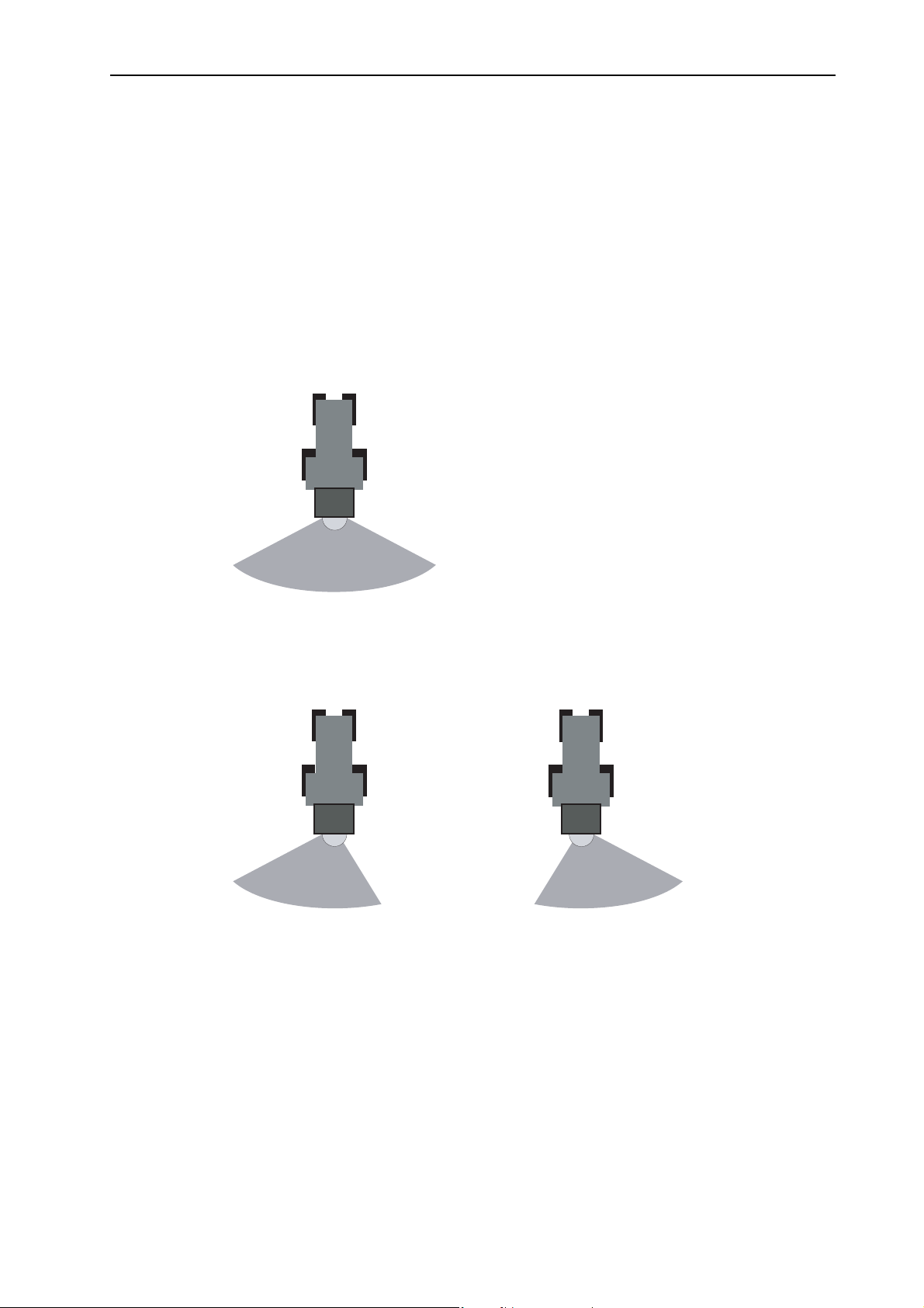
7.4 Adjusting the drop point
Altering the drop point is used for adapting to different spreading materials and
spreading patterns.
The drop point is set at the alphabetic scale of the scale plate. For this purpose,
set the stop to the position determined according to the fertiliser chart.
Adjustment towards A: The centre of gravity of the spreading pattern is shift-
ed towards the left (in direction of travel).
Adjustment towards M: The centre of gravity of the spreading pattern is shift-
ed towards the right (in direction of travel).
Symmetric spreading pattern
Machine settings
7
Figure 7.3: Symmetric spreading pattern
Asymmetric spreading pattern
Figure 7.4: Spreading to the left
Figure 7.5: Spreading to the right
(viewed in the direction
of travel)
(viewed in the direction
of travel)
55
Page 64
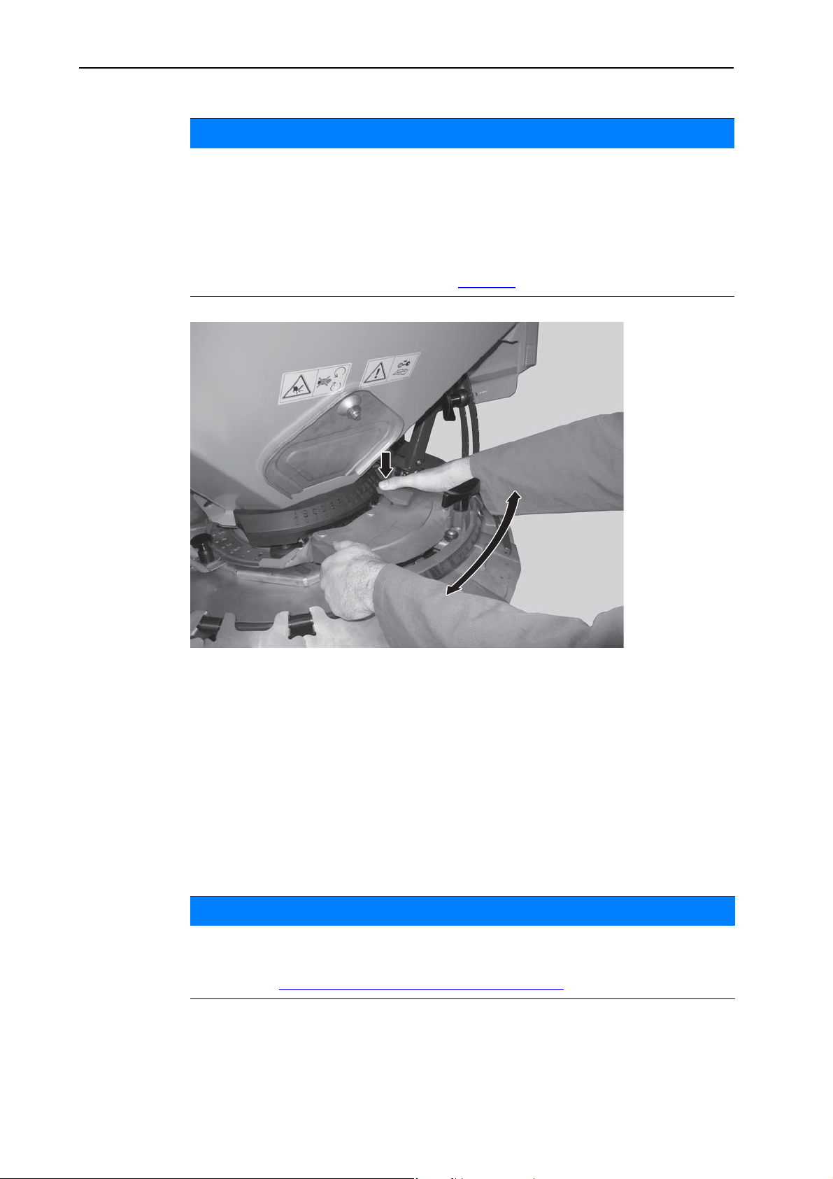
Machine settings 7
NOTICE
The following positions serve as reference for a symmetric spreading pattern determined by RAUCH for different spreading materials:
Grit: Position E
Salt: Position F
Sand: Position J
Please refer to the fertiliser chart as of Page 63
Figure 7.6: Adjustment centre for drop point
.
1. Determine the position for the drop point according to the fertiliser chart.
2. Grip the left and right handle.
3. Press the pointer unit.
The lock is released. The adjustment centre can be moved.
4. Move the adjustment centre with the pointer to the calculated position.
5. Release the pointer unit.
The adjustment centre is locked.
6. Ensure that the adjustment centre is locked.
NOTICE
If drop point adjustment is not sufficient for setting a symmetric spreading pattern, adjust the vanes on the spreading disc.
Refer to 7.8: Setting the spreading vanes, page 61.
56
Page 65

7.5 Adjusting the spreading width limiter
By means of different positions, the spreading width limiter enables spreading
widths of approx. 1 m - 8 m with a mounting height of approx. 55 cm (see specification of the mounting height Page 41
Depending on the machine equipment, 4 different spreading widths can be set.
Type of spreading width adjustment Characteristics
).
Machine settings
7
Mechanically, can be set separately on
the left and right.
Electrically, with an actuator on the right
side. Both sides are connected by a
Enables symmetric and asymmetric
spreading patterns.
Enables adjustment of the symmetric
spreading pattern while spreading.
coupling rod (optional).
Electrically, with separate actuators on
the left and right side (optional).
Enables switching from a symmetric to
an asymmetric spreading pattern
while spreading.
Electrically, with an actuator on the left
or right side (optional).
Enables single-side adjustment of the
symmetric spreading pattern while
spreading.
NOTICE
Check the proper condition of the spreading width limiter. Damaged or bent elements of the spreading width limiter affect the spreading pattern.
57
Page 66
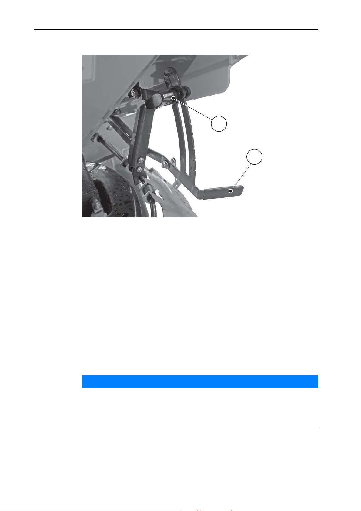
Machine settings 7
Setting:
1
2
Figure 7.7: Spreading width limiter
[1] Setscrew
[2] Adjustment lever with scale
1. Untighten the setscrew [1] at the lower end of the spreading width limiter.
2. Move the adjustment lever [2] to the desired position.
Adjustment lever to the top: The spreading width is increased.
Adjustment lever to the bottom: The spreading width is decreased.
3. Tighten the setscrew [1]
The new spreading width is set.
4. Check the spreading pattern (visual inspection or measurement) and correct
the settings as necessary.
7.6 Adjustment options with HydroControl (Version Q-100/200-HC)
NOTICE
If the machine is equipped with the HydroControl function, the disc speed and
the spreading width limiter are set at the QUANTRON-K2 control unit.
58
Please observe the separate operator's manual for the control unit. This operator's manual is supplied with the QUANTRON-K2 control unit.
Page 67
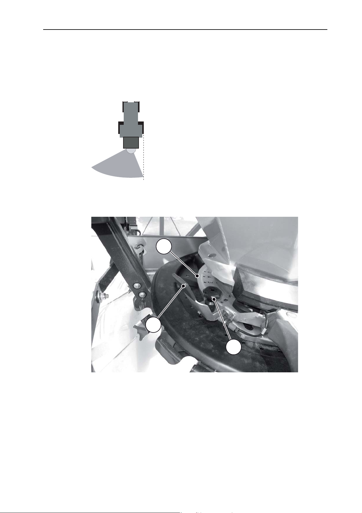
7.7 Adjusting the half-side slide
2
3
1
For sharp-edged limitation at the right edge of the path, the spreading pattern
has to be set to asymmetric spreading on the left side in direction of travel.
To enable an even spreading pattern, the half-side slide has to be adjusted additionally.
Figure 7.8: Sharp-edged limitation to the right (spreading to the left)
Machine settings
7
Half-side slide adjustment
Figure 7.9: Half-side slide adjustment
[1] Numeric scale of the scale plate
[2] Setscrew
[3] Adjustment lever
59
Page 68

Machine settings 7
1. Untighten the setscrew [2] at the half-side slide.
2. Slide the adjustment lever [3] to the desired position.
Adjustment lever towards higher numeric values: Slide is closed.
Adjustment lever towards lower numeric values: Slide is opened.
3. Tighten the setscrew [2].
4. Check the spreading pattern (visual inspection or measurement) and correct
the settings as necessary.
Information on adjustment
For sharp-edged limitation of the spreading pattern at the right edge of the path
with application rate balancing and even spreading material distribution:
Determine the adjustment values for the spreading material (fertiliser chart).
Lower the right spreading width limiter and close the half-side slide (refer to
figure 7.9
).
60
Page 69
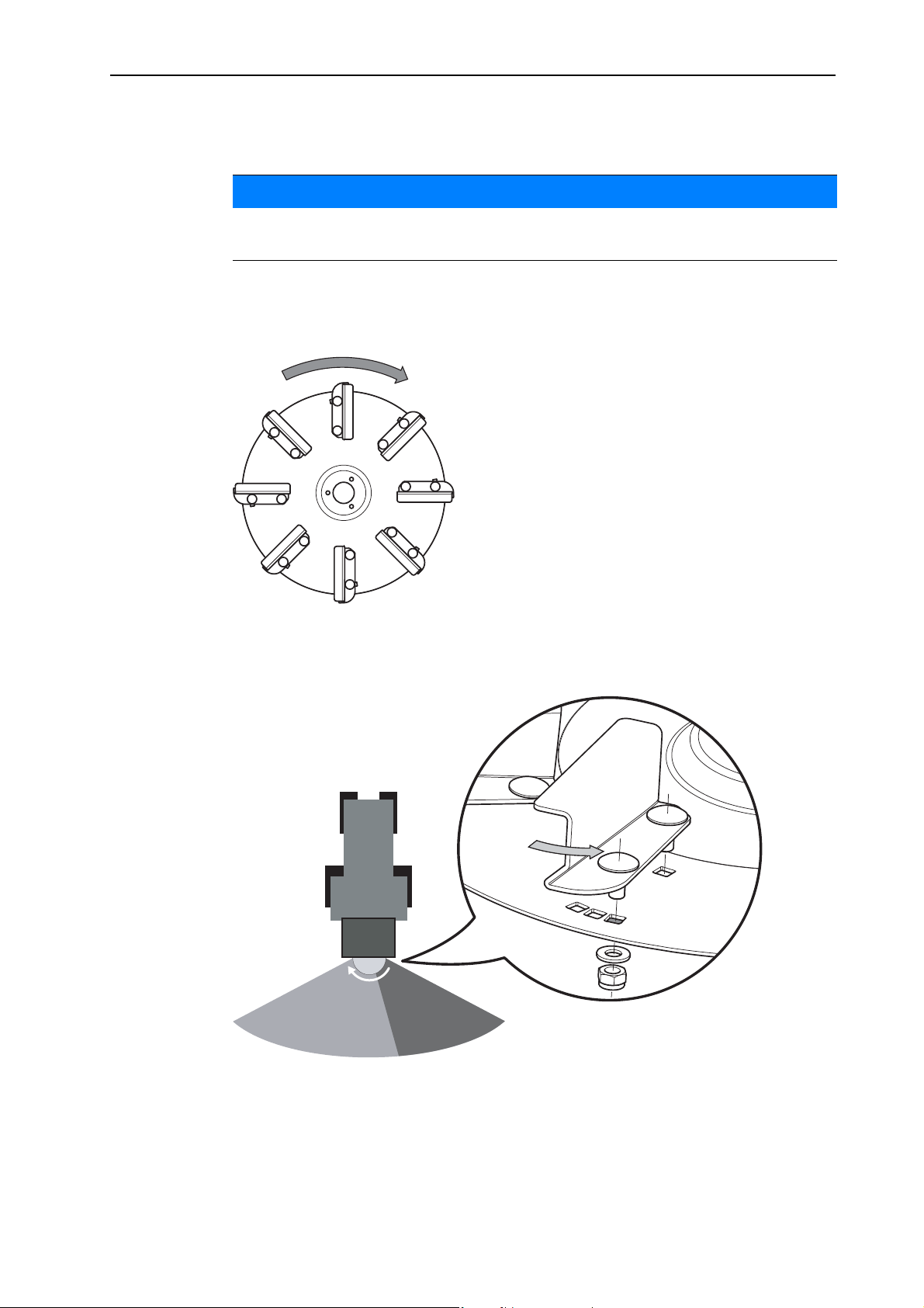
Machine settings
7.8 Setting the spreading vanes
NOTICE
If drop point adjustment is not sufficient for setting a symmetric spreading pattern, additionally adjust the vanes on the spreading disc.
7.8.1 Increasing the spreading density on the right-hand side in the direction of travel
1. Observe the rotational direction of the spreading discs.
7
Figure 7.10: Rotational direction of the spreading disc
2. Disassemble the screws of the spreading vanes including the corresponding
nuts and washers.
Figure 7.11: Spreading density on the right-hand side in the direction of travel
White arrow: Rotational direction of spreading disc
Grey arrow: Adjustment of the spreading vanes against the rotational direction of the
spreader disc
61
Page 70
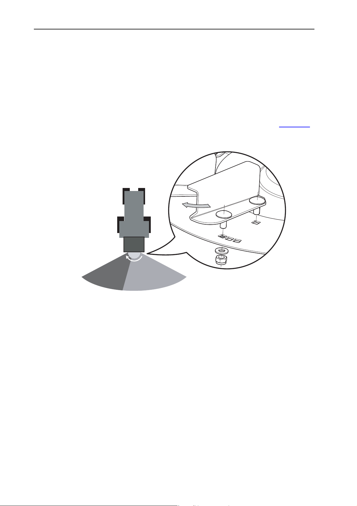
Machine settings 7
3. Reset the spreading vanes against the rotary direction of the spreading disc.
With this setting, the spreading material is ejected earlier.
4. Screw on the spreading vane (tightening torque: approx. 18 Nm). Always
use new self-locking nuts when screwing on the vane.
The spreading density on the right-hand side viewed in the direction of
travel is increased.
7.8.2 Increasing the spreading density on the left-hand side in the direction of travel
1. Observe the rotational direction of the spreading discs. Refer to figure 7.10
2. Disassemble the screws of the spreading vanes including the corresponding
nuts and washers.
.
Figure 7.12: Spreading density on the left in the direction of travel
White arrow: Rotational direction of the spreading disc
Grey arrow: Adjustment of the spreading vanes in the rotational direction of the
spreader disc
3. Set the spreading vanes in the rotary direction of the spreading disc.
Using this setting, the spreading material will be ejected later.
4. Screw on the spreading vane (tightening torque: approx. 18 Nm). Always
use new self-locking nuts when screwing on the vane.
The spreading density on the left-hand side viewed in the direction of
travel is increased.
62
Page 71

7.9 Use the fertiliser chart
7.9.1 Information on the fertiliser chart
The values in the fertiliser chart have been determined using the spreading material test system.
The spreading material used has been purchased from the manufacturer or from
dealers. Experience shows that due to storage and transport, your spreading material – even with identical specifications – might exhibit a different spreading behaviour.
This means that the settings specified in the fertiliser charts may result in a different spreading quantity and a poorer spreading material distribution.
Always check the actual application rate by means of calibration (see chapter
7.10: Calibration, page 84
Observe the setting values exactly. Even a slightly incorrect setting may ad-
versely affect the spreading pattern.
Adjustments for spreading materials not listed in the fertiliser chart can be de-
termined by means of calibration.
Machine settings
7
).
NOTICE
With small working widths, the spreading disc speed can be reduced. Implement
another calibration test with the new speed (RPM).
NOTICE
The operating staff is responsible for making the correct spreader adjustments
according to the spreading material used.
We point out specifically that we do not accept any liability for subsequent damage resulting from incorrect spreader adjustments.
63
Page 72

Machine settings 7
7.9.2 List of fertiliser charts
Further fertiliser charts can be found on the fertiliser chart CD provided or online
at www.rauch.de.
Chart Page
Fertiliser chart for grit (3/5 mm) Page 65
Fertiliser chart for sand Page 66
Fertiliser chart for rock salt Page 67
Fertiliser chart for refined salt Page 68
Fertiliser chart for fertiliser
Basatop Sport, COMPO Page 69
NOTICE
Cornufera NPK, Günther Page 70
ENTEC avant, COMPO Page 72
Floranid N32, COMPO Page 74
Floranid permanent, COMPO Page 76
Calcium-ammonium nitrate, Floral Page 77
Kornkali, K + S GmbH Page 79
Grass Floranid NPK, COMPO Page 81
Thomaskali, K + S GmbH Page 82
64
Page 73
7.9.3 Fertiliser chart for grit (3/5 mm)
PTO speed: n = 450 rpm Spreading disc speed: 200 rpm
Drop point: E Flow factor: 1.35
Mounting height: B = 33 cm Agitator type: RWK AX 160
Half-side slide: 0
Setting values for metering slide stop:
Spreading width [m] 1 2
Machine settings
7
Spreading density
2
]
[g/m
100 150 200 250 300 100 150 200 250 300
3 13151617181618202223
6 16 18 20 22 23 20 23 26 28 31
10 19 22 24 26 28 24 28 33 37 40
Forward speed
[km/h]
15 22 25 28 32 36 28 36 40 44 49
20 24 28 33 37 40 33 40 45 54 –
25 26 32 37 41 44 37 44 54 – –
30 28 36 40 44 49 40 49 – – –
Spreading width [m] 3 4
Spreading density
2
]
[g/m
100 150 200 250 300 100 150 200 250 300
3 18212325272023262831
6 23 27 31 36 38 26 31 37 40 43
10 28 36 40 44 49 33 40 45 54 –
Forward speed
[km/h]
15 36 42 49 60 – 40 49 – – –
20 40 49 – – – 45 – – – –
25 44 60 – – – 54 – – – –
3049–––––––––
Spreading width [m] 6 8
Spreading density
2
]
[g/m
100 150 200 250 300 100 150 200 250 300
3 23273136392631374043
6 31 38 43 49 – 37 43 52 – –
10 40 49 60 – – 45 – – – –
Forward speed
[km/h]
15 49 60 – – – – – – – –
2060–––––––––
25 – – – – – – – – – –
30––––––––––
65
Page 74
Machine settings 7
7.9.4 Fertiliser chart for sand
PTO speed: n = 540 rpm Spreading disc speed: 230 rpm
Drop point: J Flow factor: 0.78
Mounting height: B = 33 cm Agitator type: RWK AX 180
Half-side slide: 0
Setting values for metering slide stop:
Spreading width [m] 1 2
Spreading density
2
]
[g/m
100 150 200 250 300 100 150 200 250 300
3 16181920211921232527
6 19 22 23 25 27 23 27 30 33 35
10 22 25 28 31 33 28 33 37 41 45
Forward speed
[km/h]
15 25 30 33 36 39 33 39 45 58 –
20 28 33 37 41 45 37 45 60 – –
25 31 36 41 47 58 41 58 – – –
30 33 39 45 58 – 45 – – – –
Spreading width [m] 3 4
Spreading density
2
]
[g/m
100 150 200 250 300 100 150 200 250 300
3 21242729322327303335
6 27 32 35 39 43 30 35 40 45 56
10 33 39 45 58 – 37 45 60 – –
Forward speed
[km/h]
15 39 52 – – – 45 – – – –
20 45 60 – – – 60 – – – –
66
25 58 – – – – – – – – –
30––––––––––
Spreading width [m] 6
Spreading density
2
]
[g/m
100 150 200 250 300
3 2732353943
6 35 43 56 – –
1045––––
Forward speed
[km/h]
15 – – – – –
20–––––
25 – – – – –
30–––––
Page 75
7.9.5 Fertiliser chart for rock salt
PTO speed: n = 540 rpm Spreading disc speed: 230 rpm
Drop point: F Flow factor: 1.22
Mounting height: B = 33 cm Agitator type: RWK AX 220
Half-side slide: 0
Setting values for metering slide stop:
Machine settings
7
Spreading width
[m]
Spreading density
2
[g/m
]
Forward speed
[km/h]
Spreading width
[m]
Spreading density
2
[g/m
]
Forward speed
[km/h]
12
5 10203040 5 10203040
3–––––––––10
6 – – – – 10 – – 10 10.5 11.5
10 – – 9 10.5 11.5 – – 11.5 12.5 13.5
15 – – 10 11.5 12.5 – 10 12.5 14.5 16
20 – – 11 12.5 13.5 – 11 13.5 16 18
25 – 10.5 11.5 13.5 15 10.5 11.5 15 17.5 20
30 – 11 12.5 14.5 16 11 12.5 16 19 22
34
5 10203040 5 10203040
3 – – – 10.5 11 – – 10 11 11.5
6 – – 10.5 12 13.5 – 10 11.5 13.5 15
10 – 10.5 12.5 14.5 16 – 11.5 13.5 16 18
15 10 11.5 14.5 17 19 10 12.5 16 19 22
20 10.5 12.5 16 19 22 11 13.5 18 22 25.5
25 11 13.5 17.5 21 25 11.5 15 20 25 27.5
Spreading width
[m]
Spreading density
2
[g/m
]
Forward speed
[km/h]
30 11.5 14.5 19 23 26.5 12.5 16 22 26.5 29.5
68
5 10203040 5 10203040
3 – – 11 12 13.5 – 10 11.5 13.5 14.5
6 – 10.5 13.5 15.5 17.5 10 11.5 15 17.5 19.5
10 10.5 12.5 16 19 22 11.5 13.5 18 22 25.5
15 11.5 14.5 19 23 26.5 12.5 16 22 26.5 29.5
20 12.5 16 22 26.5 29.5 13.5 18 25.5 29.5 34.5
25 13.5 17.5 25 29 33.5 15 20 27.5 33.5 39
30 14.5 19 26.5 31.5 37 16 22 29.5 37 44
67
Page 76
Machine settings 7
7.9.6 Fertiliser chart for refined salt
PTO speed: n = 540 rpm Spreading disc speed: 230 rpm
Drop point: F Flow factor: 1.38
Mounting height: B = 33 cm Agitator type: RWK AX 220
Half-side slide: 0
Setting values for metering slide stop:
Spreading width
[m]
Spreading density
2
[g/m
]
Forward speed
[km/h]
Spreading width
[m]
Spreading density
2
[g/m
]
Forward speed
[km/h]
12
5 10 20 30 40 5 10 20 30 40
3––––––––66.5
6 – – 5.5 6 6.5 – – 6.5 7 8
10 – – 6 7 7.5 – 6 7.5 9 10.5
15 – – 7 8 9 – 7 9 11 12.5
20 – 6 7.5 9 10.5 6 7.5 10.5 12.5 14
25 – 6.5 8 10.5 11.5 6.5 8 11.5 13.5 15
30 6 7 9 11 12 7 9 12 14.5 16.5
34
5 10 20 30 40 5 10 20 30 40
3––66.57.5––6.57.58
6 – 6 7 8.5 10.5 – 6.5 8 10.5 11.5
10 – 7 9 11 12.5 6 7.5 10.5 12.5 13.5
15 6 8 11 12.5 14.5 7 9 12.5 14.5 16.5
20 7 9 12.5 14.5 16.5 7.5 10.5 14 16.5 19
25 7.5 10.5 13.5 16 18.5 8 11.5 15 18.5 21.5
68
Spreading width
[m]
Spreading density
2
[g/m
]
Forward speed
[km/h]
30 8 11 14.5 17.5 20.5 9 12 16.5 20.5 23.5
5
5 10203040
3– – 7 89.5
6 – 7 9.5 11 12.5
10 6.5 8.5 11.5 13.5 15.5
15 7.5 10.5 13.5 16 18.5
20 8.5 11.5 15.5 18.5 21.5
25 9.5 12.5 17 20.5 23.5
30 10.5 13.5 18.5 22.5 26
Page 77
7.9.7 Fertiliser chart for fertiliser
Basatop Sport, COMPO
NPK: 20 - 5 - 10
Fertiliser density: 1.10 kg/l
Half-side slide: 5
Application rate in kg/ha
Agitator type: RWK AX 140
Spreading width 5 6 7 8
PTO speed (rpm) 540 540 750 1000
Disc speed (rpm) 230 230 325 430
Mounting height 33 33 33 33
Drop point H H I I
Machine settings
7
Metering
slide stop
Flow rate
(kg/s)
km / h km / h km / h km / h
81012810128101281012
20 12.5 188 150 125 156 125 104 134 107 89 117 94 78
21 14.8 222 178 148 185 148 123 159 127 106 139 111 93
22 17.1 257 205 171 214 171 143 183 147 122 160 128 107
23 19.4 291 233 194 243 194 162 208 166 139 182 146 121
24 21.7 326 260 217 271 217 181 233 186 155 203 163 136
25 24.0 360 288 240 300 240 200 257 206 171 225 180 150
26 24.7 371 297 247 309 247 206 265 212 177 232 185 155
27 25.4 382 305 254 318 254 212 273 218 182 239 191 159
28 26.2 392 314 262 327 262 218 280 224 187 245 196 164
29 26.9 403 323 269 336 269 224 288 230 192 252 202 168
30 27.6 414 331 276 345 276 230 296 237 197 259 207 173
31 29.0 435 348 290 362 290 242 311 248 207 272 217 181
32 30.4 455 364 304 380 304 253 325 260 217 285 228 190
33 31.7 476 381 317 397 317 265 340 272 227 298 238 198
34 33.1 497 397 331 414 331 276 355 284 237 311 248 207
35 34.5 518 414 345 431 345 288 370 296 246 323 259 216
36 36.6 550 440 366 458 366 305 393 314 262 344 275 229
37 38.8 582 465 388 485 388 323 416 332 277 364 291 242
38 40.9 614 491 409 512 409 341 438 351 292 384 307 256
39 43.1 646 517 431 538 431 359 461 369 308 404 323 269
40 45.2 678 542 452 565 452 377 484 387 323 424 339 283
69
Page 78
Machine settings 7
Cornufera NPK, Günther
NPK: 20 - 5 - 8
Fertiliser density: 1.10 kg/l
Half-side slide: 5
Application rate in kg/ha
Agitator type: RWK AX 140
Spreading width 5 6 7 8
PTO speed (rpm) 540 750 750 1000
Disc speed (rpm) 230 325 325 430
Mounting height 33 33 33 33
Drop point J K K K
Metering
slide stop
Flow rate
(kg/s)
km / h km / h km / h km / h
8 10 12 8 10 12 8 10 12 8 10 12
20 9.6 144 115 96 120 96 80 103 82 69 90 72 60
21 11.4 170 136 114 142 114 95 122 97 81 107 85 71
22 13.1 197 157 131 164 131 109 141 112 94 123 98 82
23 14.9 223 179 149 186 149 124 159 128 106 140 112 93
24 16.6 250 200 166 208 166 139 178 143 119 156 125 104
25 18.4 276 221 184 230 184 153 197 158 131 173 138 115
26 20.2 303 243 202 253 202 169 217 173 144 190 152 126
27 22.0 331 264 220 276 220 184 236 189 157 207 165 138
28 23.9 358 286 239 298 239 199 256 205 170 224 179 149
29 25.7 385 308 257 321 257 214 275 220 183 241 193 161
30 27.5 413 330 275 344 275 229 295 236 196 258 206 172
31 29.6 444 355 296 370 296 247 317 254 211 278 222 185
33 33.8 507 406 338 423 338 282 362 290 241 317 254 211
32 31.7 476 380 317 396 317 264 340 272 226 297 238 198
70
34 35.9 539 431 359 449 359 299 385 308 256 337 269 224
35 38.0 570 456 380 475 380 317 407 326 271 356 285 238
36 40.0 601 480 400 501 400 334 429 343 286 375 300 250
37 42.1 631 505 421 526 421 351 451 361 301 395 316 263
38 44.1 662 529 441 552 441 368 473 378 315 414 331 276
39 46.2 692 554 462 577 462 385 495 396 330 433 346 289
Page 79
Machine settings
Spreading width 5 6 7 8
PTO speed (rpm) 540 750 750 1000
Disc speed (rpm) 230 325 325 430
Mounting height 33 33 33 33
Drop point J K K K
7
Metering
slide stop
Flow rate
(kg/s)
km / h km / h km / h km / h
81012810128101281012
40 48.2 723 578 482 603 482 402 516 413 344 452 362 301
41 50.3 754 603 503 629 503 419 539 431 359 471 377 314
42 52.4 785 628 524 655 524 436 561 449 374 491 393 327
43 54.4 817 653 544 681 544 454 583 467 389 510 408 340
44 56.5 848 678 565 707 565 471 606 484 404 530 424 353
45 58.6 879 703 586 733 586 488 628 502 419 549 440 366
71
Page 80
Machine settings 7
ENTEC avant, COMPO
NPK: 12 - 7 - 6
Fertiliser density: 1.13 kg/l
Half-side slide: 5
Application rate in kg/ha
Agitator type: RWK AX 140
Spreading width 5 6 7 8
PTO speed (rpm) 540 540 750 1000
Disc speed (rpm) 230 230 325 430
Mounting height 33 33 33 33
Drop point I I I I
Metering
slide stop
Flow
rate
(kg/s)
km / h km / h km / h km / h
8 1012 8 1012 8 1012 8 1012
20 12.0 180 144 120 150 120 100 129 103 86 113 90 75
21 14.0 210 168 140 175 140 117 150 120 100 131 105 88
22 16.0 240 192 160 200 160 133 171 137 114 150 120 100
23 18.0 270 216 180 225 180 150 193 154 129 169 135 113
24 20.0 300 240 200 250 200 167 214 171 143 188 150 125
25 22.0 330 264 220 275 220 183 236 189 157 206 165 138
26 24.3 364 291 243 304 243 202 260 208 173 228 182 152
27 26.6 398 319 266 332 266 221 285 228 190 249 199 166
28 28.8 433 346 288 361 288 240 309 247 206 270 216 180
29 31.1 467 373 311 389 311 259 333 267 222 292 233 195
30 33.4 501 401 334 418 334 278 358 286 239 313 251 209
31 36.0 539 432 360 450 360 300 385 308 257 337 270 225
32 38.5 578 462 385 482 385 321 413 330 275 361 289 241
72
33 41.1 616 493 411 514 411 342 440 352 293 385 308 257
34 43.6 655 524 436 546 436 364 468 374 312 409 327 273
35 46.2 693 554 462 578 462 385 495 396 330 433 347 289
36 48.9 733 586 489 611 489 407 524 419 349 458 366 305
37 51.5 773 618 515 644 515 429 552 442 368 483 386 322
38 54.2 813 650 542 677 542 452 581 464 387 508 406 339
39 56.8 853 682 568 711 568 474 609 487 406 533 426 355
40 59.5 893 714 595 744 595 496 638 510 425 558 446 372
41 62.0 930 744 620 775 620 517 664 531 443 581 465 387
42 64.5 967 774 645 806 645 537 691 553 460 604 483 403
43 66.9 1004 803 669 837 669 558 717 574 478 628 502 418
Page 81
Machine settings
Spreading width 5 6 7 8
PTO speed (rpm) 540 540 750 1000
Disc speed (rpm) 230 230 325 430
Mounting height 33 33 33 33
Drop point I I I I
7
Metering
slide stop
Flow
rate
(kg/s)
km / h km / h km / h km / h
8 1012 8 1012 8 1012 8 1012
44 69.4 1041 833 694 868 694 579 744 595 496 651 521 434
45 71.9 1079 863 719 899 719 599 770 616 514 674 539 449
46 74.1 1111 889 741 926 741 617 794 635 529 694 555 463
47 76.2 1143 915 762 953 762 635 817 653 544 715 572 476
48 78.4 1176 941 784 980 784 653 840 672 560 735 588 490
49 80.5 1208 966 805 1007 805 671 863 690 575 755 604 503
50 82.7 1241 992 827 1034 827 689 886 709 591 775 620 517
73
Page 82
Machine settings 7
Floranid N32, COMPO
32 % N
Fertiliser density: 0.52 kg/l
Half-side slide: 5
Application rate in kg/ha
Agitator type: RWK AX 140
Spreading width 3 4 5 6
PTO speed (rpm) 540 750 1000 1000
Disc speed (rpm) 230 325 430 430
Mounting height 33 33 33 33
Drop point L M M K
Metering
slide stop
Flow
rate
(kg/s)
km / h km / h km / h km / h
8 1012 8 1012 8 1012 8 1012
15 3.0 756050564538453630383025
16 3.7 94 75 62 70 56 47 56 45 37 47 37 31
17 4.5 112 90 75 84 67 56 67 54 45 56 45 37
19 6.0 149 119 99 112 89 75 89 72 60 75 60 50
18 5.2 131 104 87 98 78 65 78 63 52 65 52 44
20 6.7 168 134 112 126 101 84 101 80 67 84 67 56
21 7.8 196 156 130 147 117 98 117 94 78 98 78 65
22 8.9 224 179 149 168 134 112 134 107 89 112 89 75
23 10.1 252 201 168 189 151 126 151 121 101 126 101 84
24 11.2 280 224 186 210 168 140 168 134 112 140 112 93
25 12.3 308 246 205 231 185 154 185 148 123 154 123 103
26 13.3 333 266 222 250 200 167 200 160 133 167 133 111
27 14.3 359 287 239 269 215 179 215 172 143 179 143 120
74
28 15.4 384 307 256 288 230 192 230 184 154 192 154 128
29 16.4 410 328 273 307 246 205 246 197 164 205 164 137
30 17.4 435 348 290 326 261 218 261 209 174 218 174 145
31 18.7 467 373 311 350 280 233 280 224 187 233 187 156
32 19.9 498 398 332 374 299 249 299 239 199 249 199 166
33 21.2 530 424 353 397 318 265 318 254 212 265 212 177
34 22.4 561 449 374 421 337 281 337 269 224 281 224 187
35 23.7 593 474 395 444 356 296 356 284 237 296 237 198
36 24.7 618 494 412 464 371 309 371 297 247 309 247 206
37 25.7 644 515 429 483 386 322 386 309 257 322 257 215
38 26.8 669 535 446 502 401 335 401 321 268 335 268 223
Page 83
Machine settings
Spreading width 3 4 5 6
PTO speed (rpm) 540 750 1000 1000
Disc speed (rpm) 230 325 430 430
Mounting height 33 33 33 33
Drop point L M M K
7
Metering
slide stop
Flow
rate
(kg/s)
km / h km / h km / h km / h
81012810128101281012
39 27.8 695 556 463 521 417 347 417 333 278 347 278 232
40 28.8 720 576 480 540 432 360 432 346 288 360 288 240
41 29.5 739 591 492 554 443 369 443 354 295 369 295 246
42 30.3 757 606 505 568 454 379 454 363 303 379 303 252
43 31.0 776 620 517 582 465 388 465 372 310 388 310 259
44 31.8 794 635 529 596 476 397 476 381 318 397 318 265
45 32.5 813 650 542 609 488 406 488 390 325 406 325 271
46 33.0 825 660 550 619 495 413 495 396 330 413 330 275
47 33.5 838 670 558 628 503 419 503 402 335 419 335 279
48 34.0 850 680 567 638 510 425 510 408 340 425 340 283
49 34.5 863 690 575 647 518 431 518 414 345 431 345 288
50 35.0 875 700 583 656 525 438 525 420 350 438 350 292
75
Page 84
Machine settings 7
Floranid permanent, COMPO
NPK: 16 - 7 - 15
Fertiliser density: 1.01 kg/l
Half-side slide: 5
Application rate in kg/ha
Agitator type: RWK AX 140
Spreading width 5 6 7 8
PTO speed (rpm) 540 750 750 1000
Disc speed (rpm) 230 325 325 430
Mounting height 33 33 33 33
Drop point L L L I
Metering
slide stop
Flow rate
(kg/s)
km / h km / h km / h km / h
8 10 12 8 10 12 8 10 12 8 10 12
20 11.5 173 138 115 144 115 96 123 99 82 108 86 72
21 13.4 201 161 134 168 134 112 144 115 96 126 101 84
22 15.3 230 184 153 191 153 128 164 131 109 143 115 96
23 17.2 258 206 172 215 172 143 184 147 123 161 129 108
24 19.1 287 229 191 239 191 159 205 164 136 179 143 119
25 21.0 315 252 210 263 210 175 225 180 150 197 158 131
26 23.4 352 281 234 293 234 195 251 201 167 220 176 147
27 25.9 388 311 259 324 259 216 277 222 185 243 194 162
28 28.3 425 340 283 354 283 236 303 243 202 266 212 177
29 30.8 461 369 308 385 308 256 330 264 220 288 231 192
30 33.2 498 398 332 415 332 277 356 285 237 311 249 208
31 35.8 536 429 358 447 358 298 383 307 255 335 268 224
32 38.3 575 460 383 479 383 319 411 328 274 359 287 240
33 40.9 613 491 409 511 409 341 438 350 292 383 307 256
76
34 43.4 652 521 434 543 434 362 465 372 310 407 326 272
35 46.0 690 552 460 575 460 383 493 394 329 431 345 288
36 48.4 726 581 484 605 484 403 519 415 346 454 363 303
37 50.8 762 610 508 635 508 423 544 435 363 476 381 318
38 53.2 798 638 532 665 532 443 570 456 380 499 399 333
39 55.6 834 667 556 695 556 463 596 477 397 521 417 348
40 58.0 870 696 580 725 580 483 621 497 414 544 435 363
Page 85
Machine settings
Calcium-ammonium nitrate, Floral
27 % N
Fertiliser density: 1.07 kg/l
Half-side slide: 5
Application rate in kg/ha
Agitator type: RWK AX 140
Spreading width 5 6 7 8 9
PTO speed (rpm) 540 750 1000 1000 1000
Disc speed (rpm) 230 325 430 430 430
Mounting height 33 33 33 33 33
Drop point G G H H H
7
Metering
slide stop
Flow rate
(kg/s)
km / h km / h km / h km / h km / h
8101281012810128101281012
20 11.0 165 132 110 138 110 92 118 94 79 103 83 69 92 73 61
21 12.7 191 153 127 159 127 106 136 109 91 119 95 80 106 85 71
22 14.4 217 173 144 181 144 120 155 124 103 135 108 90 120 96 80
23 16.2 242 194 162 202 162 135 173 139 115 152 121 101 135 108 90
24 17.9 268 215 179 224 179 149 192 153 128 168 134 112 149 119 99
25 19.6 294 235 196 245 196 163 210 168 140 184 147 123 163 131 109
26 21.8 327 262 218 273 218 182 234 187 156 204 164 136 182 145 121
27 24.0 360 288 240 300 240 200 257 206 171 225 180 150 200 160 133
28 26.2 393 314 262 328 262 218 281 225 187 246 197 164 218 175 146
29 28.4 426 341 284 355 284 237 304 243 203 266 213 178 237 189 158
30 30.6 459 367 306 383 306 255 328 262 219 287 230 191 255 204 170
31 32.6 490 392 326 408 326 272 350 280 233 306 245 204 272 218 181
32 34.7 520 416 347 434 347 289 372 297 248 325 260 217 289 231 193
33 36.7 551 441 367 459 367 306 393 315 262 344 275 230 306 245 204
34 38.8 581 465 388 485 388 323 415 332 277 363 291 242 323 258 215
35 40.8 612 490 408 510 408 340 437 350 291 383 306 255 340 272 227
36 43.2 649 519 432 541 432 360 463 371 309 405 324 270 360 288 240
37 45.7 685 548 457 571 457 381 489 392 326 428 343 286 381 305 254
38 48.1 722 577 481 602 481 401 516 412 344 451 361 301 401 321 267
39 50.6 758 607 506 632 506 421 542 433 361 474 379 316 421 337 281
40 53.0 795 636 530 663 530 442 568 454 379 497 398 331 442 353 294
41 55.4 831 665 554 693 554 462 594 475 396 519 416 346 462 369 308
42 57.8 867 694 578 723 578 482 619 495 413 542 434 361 482 385 321
77
Page 86
Machine settings 7
Spreading width 5 6 7 8 9
PTO speed (rpm) 540 750 1000 1000 1000
Disc speed (rpm) 230 325 430 430 430
Mounting height 33 33 33 33 33
Drop point G G H H H
Metering
slide stop
Flow rate
(kg/s)
km / h km / h km / h km / h km / h
8101281012810128101281012
43 60.2 903 722 602 753 602 502 645 516 430 564 452 376 502 401 334
44 62.6 939 751 626 783 626 522 671 537 447 587 470 391 522 417 348
45 65.0 975 780 650 813 650 542 696 557 464 609 488 406 542 433 361
78
Page 87
Machine settings
Kornkali, K + S GmbH
40 % K, 6 % MgO
Fertiliser density: 1.15 kg/l
Half-side slide: 5
Application rate in kg/ha
Agitator type: RWK AX 140
Spreading width 4 5 6 7
PTO speed (rpm) 540 540 850 1000
7
Disc speed
230 230 370 430
(rpm)
Mounting height 33 33 33 33
Drop point L L L L
Metering
slide
Flow
rate
(kg/s)
km / h km / h km / h km / h
8 10 12 8 10 12 8 10 12 8 10 12
stop
20 10.5 197 158 131 158 126 105 131 105 88 113 90 75
21 12.1 227 182 152 182 145 121 152 121 101 130 104 87
22 13.7 258 206 172 206 165 137 172 137 115 147 118 98
23 15.4 288 230 192 230 184 154 192 154 128 165 132 110
24 17.0 318 255 212 255 204 170 212 170 142 182 146 121
25 18.6 349 279 233 279 223 186 233 186 155 199 159 133
26 20.7 388 310 259 310 248 207 259 207 172 222 177 148
27 22.8 427 341 285 341 273 228 285 228 190 244 195 163
28 24.8 466 373 311 373 298 248 311 248 207 266 213 177
29 26.9 505 404 337 404 323 269 337 269 224 288 231 192
30 29.0 544 435 363 435 348 290 363 290 242 311 249 207
31 31.3 587 470 392 470 376 313 392 313 261 336 268 224
32 33.6 631 505 421 505 404 336 421 336 280 360 288 240
33 36.0 674 539 450 539 432 360 450 360 300 385 308 257
34 38.3 718 574 479 574 459 383 479 383 319 410 328 273
35 40.6 761 609 508 609 487 406 508 406 338 435 348 290
36 42.3 793 634 529 634 507 423 529 423 352 453 362 302
37 44.0 824 659 550 659 528 440 550 440 366 471 377 314
38 45.6 856 685 571 685 548 456 571 456 380 489 391 326
39 47.3 887 710 592 710 568 473 592 473 394 507 406 338
40 49.0 919 735 613 735 588 490 613 490 408 525 420 350
41 51.1 959 767 639 767 614 511 639 511 426 548 438 365
42 53.3 999 799 666 799 639 533 666 533 444 571 457 381
79
Page 88
Machine settings 7
Spreading width 4 5 6 7
PTO speed (rpm) 540 540 850 1000
Disc speed
230 230 370 430
(rpm)
Mounting height 33 33 33 33
Drop point L L L L
Metering
slide
Flow
rate
(kg/s)
km / h km / h km / h km / h
8 10 12 8 10 12 8 10 12 8 10 12
stop
43 55.4 1039 831 693 831 665 554 693 554 462 594 475 396
44 57.6 1079 863 720 863 691 576 720 576 480 617 493 411
45 59.7 1119 896 746 896 716 597 746 597 498 640 512 426
46 61.3 1149 919 766 919 735 613 766 613 511 656 525 438
47 62.8 1178 942 785 942 754 628 785 628 524 673 538 449
48 64.4 1207 966 805 966 773 644 805 644 537 690 552 460
49 65.9 1236 989 824 989 791 659 824 659 550 707 565 471
50 67.5 1266 1013 844 1013 810 675 844 675 563 723 579 482
80
Page 89
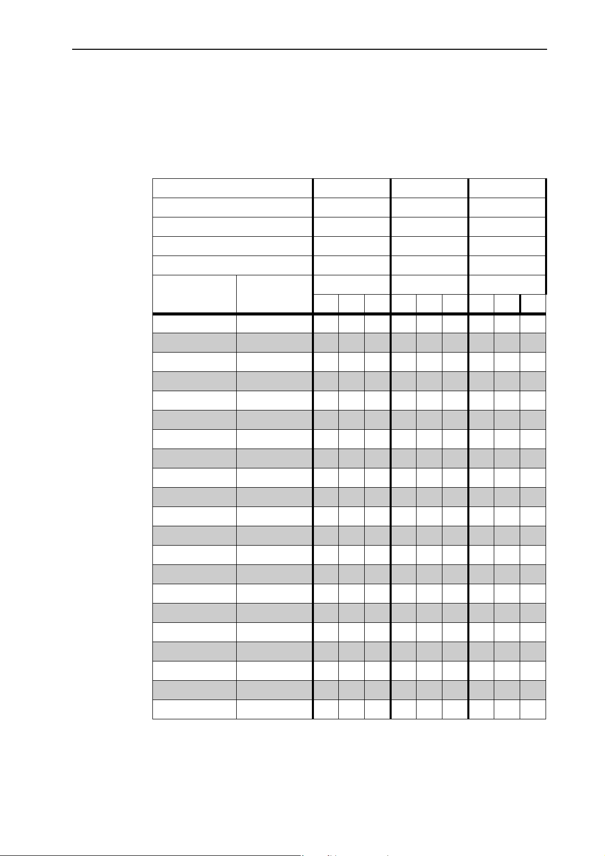
Machine settings
Grass Floranid NPK, COMPO
NPK: 20 - 5 - 8
Fertiliser density: 0.90 kg/l
Half-side slide: 5
Application rate in kg/ha
Agitator type: RWK AX 140
Spreading width 5 6 7
PTO speed (rpm) 540 750 100
Disc speed (rpm) 230 325 430
Mounting height 33 33 33
Drop point L M M
7
Metering slide
stop
20 12.5 188 150 125 156 125 104 134 107 89
21 14.6 218 175 146 182 146 121 156 125 104
22 16.6 249 199 166 208 166 139 178 142 119
23 18.7 280 224 187 234 187 156 200 160 133
24 20.7 311 249 207 259 207 173 222 178 148
25 22.8 342 274 228 285 228 190 244 195 163
26 25.3 380 304 253 317 253 211 272 217 181
27 27.9 418 335 279 349 279 232 299 239 199
28 30.4 456 365 304 380 304 254 326 261 217
29 33.0 494 396 330 412 330 275 353 283 235
30 35.5 533 426 355 444 355 296 380 304 254
31 37.9 568 454 379 473 379 316 406 325 270
32 40.2 603 483 402 503 402 335 431 345 287
33 42.6 639 511 426 532 426 355 456 365 304
Flow rate
(kg/s)
km / h km / h km / h
8 1012 8 1012 8 1012
34 44.9 674 539 449 562 449 375 482 385 321
35 47.3 710 568 473 591 473 394 507 405 338
36 49.8 747 597 498 622 498 415 533 427 356
37 52.3 784 627 523 653 523 436 560 448 373
38 54.7 821 657 547 684 547 456 587 469 391
39 57.2 858 687 572 715 572 477 613 490 409
40 59.7 896 716 597 746 597 498 640 512 426
81
Page 90
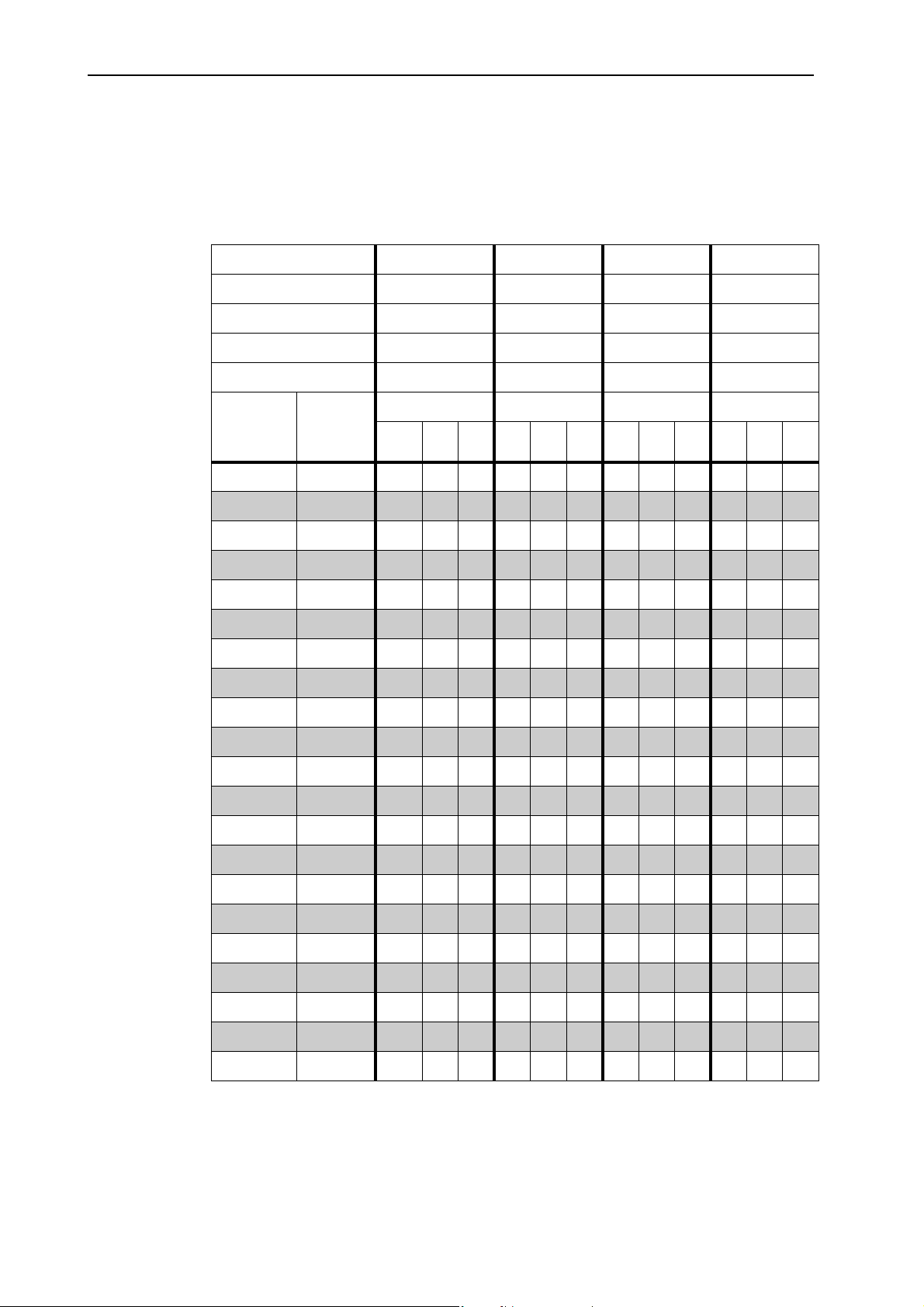
Machine settings 7
Thomaskali, K + S GmbH
10 % P - 15 % K
Fertiliser density: 1.35 kg/l
Application rate in kg/ha
Agitator type: RWK AX 140
Spreading width 5 6 7 8
PTO speed (rpm) 540 750 1000 1000
Disc speed (rpm) 230 325 430 430
Mounting height 33 33 33 33
Drop point J J K K
Metering
slide stop
Flow
rate
(kg/s)
km / h km / h km / h km / h
8 1012810128101281012
20 11.3 170 136 113 141 113 94 121 97 81 106 85 71
21 13.3 200 160 133 167 133 111 143 114 95 125 100 83
22 15.4 231 185 154 192 154 128 165 132 110 144 115 96
23 17.4 261 209 174 218 174 145 187 149 124 163 131 109
24 19.5 292 234 195 243 195 162 209 167 139 182 146 122
25 21.5 323 258 215 269 215 179 230 184 154 202 161 134
26 23.8 357 286 238 298 238 198 255 204 170 223 179 149
27 26.1 392 313 261 326 261 218 280 224 186 245 196 163
28 28.4 426 341 284 355 284 237 304 243 203 266 213 178
29 30.7 461 368 307 384 307 256 329 263 219 288 230 192
30 33.0 495 396 330 413 330 275 354 283 236 309 248 206
31 35.8 537 430 358 448 358 298 384 307 256 336 269 224
32 38.6 579 463 386 483 386 322 414 331 276 362 290 241
82
33 41.4 621 497 414 518 414 345 444 355 296 388 311 259
34 44.2 663 530 442 553 442 368 474 379 316 414 332 276
35 47.0 705 564 470 588 470 392 504 403 336 441 353 294
36 50.1 752 602 501 627 501 418 537 430 358 470 376 313
37 53.3 799 639 533 666 533 444 571 457 381 500 400 333
38 56.4 846 677 564 705 564 470 605 484 403 529 423 353
39 59.6 893 715 596 745 596 496 638 511 425 558 447 372
40 62.7 941 752 627 784 627 523 672 537 448 588 470 392
Page 91
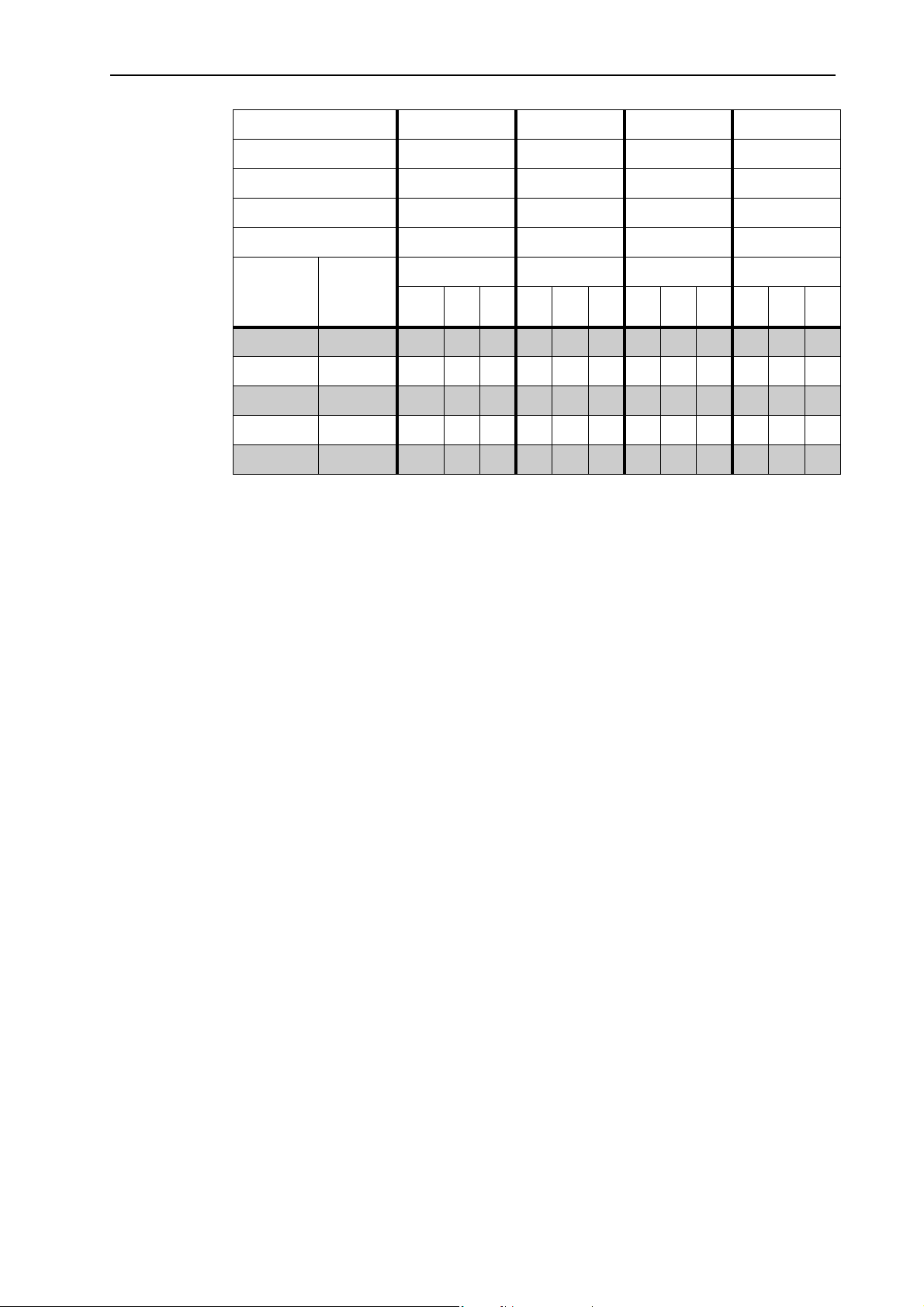
Machine settings
Spreading width 5 6 7 8
PTO speed (rpm) 540 750 1000 1000
Disc speed (rpm) 230 325 430 430
Mounting height 33 33 33 33
Drop point J J K K
7
Metering
slide stop
Flow
rate
(kg/s)
km / h km / h km / h km / h
8 10 12 8 10 12 8 10 12 8 10 12
41 65.0 974 780 650 812 650 541 696 557 464 609 487 406
42 67.2 1008 807 672 840 672 560 720 576 480 630 504 420
43 69.5 1042 834 695 869 695 579 744 596 496 651 521 434
44 71.7 1076 861 717 897 717 598 769 615 512 673 538 448
45 74.0 1110 888 740 925 740 617 793 634 529 694 555 463
83
Page 92

Machine settings 7
7.10 Calibration
For precise control of the application rate, we recommend running a new calibration every time you change spreading material types.
Carry out calibration:
Before spreading for the first time.
If the quality of the spreading material has changed significantly (moisture,
If a new type of spreading material is used.
The calibration must be conducted with engaged PTO at a standstill or during
travel over a test track.
Execute the calibration test for single-disc spreader version Q at the
QUANTRON-K2 control unit.
The calibration is described in a separate operator's manual for the
QUANTRON-K2 control unit. This operator's manual is an integral part of the
QUANTRON-K2 control unit.
high dust content, cracked grain).
NOTICE
7.10.1 Determining the nominal output rate
Calculate the nominal output rate before starting the calibration test.
To calculate the nominal output rate per minute you will require the following information:
The forward speed,
the working width,
The desired application rate
Example: You wish to calculate the nominal output rate. Your forward speed is
3km/h, the working width is specified to be 4m and the application rate shall
amount to 50 g/m
2
.
If you cannot find your values in the fertiliser chart, the nominal output rate is to
be determined by means of a formula.
Nominal output rate
= Forward speed (km/h) x working width (m) x application rate (g/m2)
(kg/min)
60
84
Example: 3km/h x 4m x 50g/m
60
2
=10kg/min
Page 93
7.10.2 Implementing the calibration
Risk of injury due to chemicals
Discharged spreading material may cause injury to eyes and nasal
mucous membranes.
Wear protective goggles during the calibration test.
Before running the calibration test, ensure that all people
leave the hazard zone of the machine.
Requirements:
The metering slide is closed.
PTO and tractor engine are switched off and locked to prevent unauthorised
starting.
An adequately sized hopper is ready for collecting the discharged spreading
material. The empty weight of the hopper is known.
n WARNING
Machine settings
7
Using the fertiliser chart, the pre-set values for the metering slide stop are de-
termined and known.
NOTICE
Select the calibration time to obtain the maximum spreading material quantity.
The greater the quantity, the greater the precision of the measurement (e. g.:
Target output volume: 10 kg/min, calibration test time: 3 min, used spreading
material quantity: 30 kg).
Proceed as follows:
n WARNING
Risk of injury due to rotating machine components.
Contact with rotating machine components (universal drive shaft,
spreading discs and agitators) may cause bruises, abrasions and
crushing injuries. Body parts or objects may be caught and pulled in.
Keep clear from rotating hubs while the machine is running.
Before running the calibration test, ensure that all people
leave the hazard zone of the machine.
1. Mount the agitator indicated in the fertiliser chart for the respective spreading
material. Refer to 7.9: Use the fertiliser chart, page 63
.
2. Fill the machine.
3.
Place a foil or a hopper for collecting the spreading material under the machine.
4. Set the adjustment lever of the spreading width limiter to the lower stop (lowest spreading width).
85
Page 94

Machine settings 7
5. Set the drop point to the position indicated in the fertiliser chart for the respec-
tive spreading material.
6. Set the half-side slide to the position indicated in the fertiliser chart for the respective spreading material.
7. Set the metering slide stop to the scale value specified in the fertiliser chart.
8. Activate the tractor and the drive of the machine.
9. Open the metering slide for the calibration test time stipulated before (e.g. 60
seconds). Close the metering slide when this time has elapsed.
10. Deactivate the drive of the machine and the tractor. Remove the ignition key.
11. Determine the collected weight.
12. Compare the actual quantity with the target quantity.
Actual quantity = target quantity: Application rate stop is set correctly.
End calibration test.
Actual quantity < target quantity: Set the application rate stop to a higher
position and repeat the calibration test.
Actual quantity > target quantity: Set the application rate stop to a lower
position and repeat the calibration test.
86
Page 95

8 Spreading work
8.1 General information
The modern technology and design of the machine and exhaustive, continuous
testing in the factory's spreading material test facilities ensure that you will have
a perfect spreading pattern.
Our machines are manufactured with utmost diligence. However, deviations in
the application rate or possible faults cannot be excluded, even when complying
with the intended use.
The reasons for this may be:
Changes in the physical characteristics of the spreading material due to the
running agitator during transportation (e.g. varying fractional composition,
varying density, grain form and surface, humidity).
Clumping and moist spreading material.
Wind drift: In the case of excessive wind speed, cancel the spreading work.
Blockages or bridge formation, e. g. due to foreign bodies, bag residue or
moist spreading material ...
Spreading work
8
Uneven ground.
Abrasion of wear parts, e.g. agitator, spreading vanes, outlet.
Damage from external causes.
Inadequate cleaning and care to prevent corrosion.
Incorrect drive speeds and forward speeds.
Calibration test has not been carried out or calibration test has been carried
out with incorrect values (e.g. incorrect PTO speed).
Incorrect machine adjustments.
NOTICE
Cleaning after each use of the machine prevents deposits at the bottom of the
hopper. You can thus reduce the wear of the agitator and increase the operational reliability of your machine.
Pay close attention to the machine settings. Even a minor deviation from the correct setting may significantly affect the spreading pattern. Therefore, before each
operation and during operation, check the correct functioning of your machine
and ensure that the application accuracy is sufficient. Carry out a calibration test.
87
Page 96
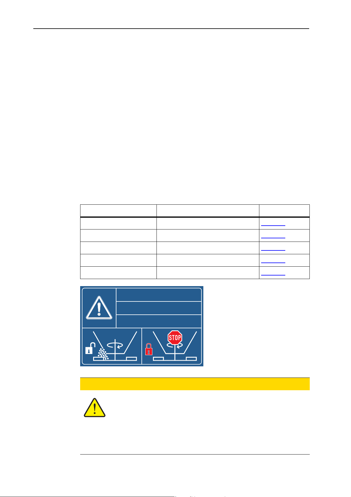
Spreading work 8
Select the PTO speed and/or the spreading disc speed in such a way that the desired spreading width can be achieved and no deposits form on the spreading
disc. A low PTO speed/spreading disc speed reduces the wear on the agitator
and spreading disc.
Particularly hard spreading material, e.g. grit, increases the wear on the spreading vanes.
For spreading, select the PTO speed and/or the spreading disc speed with which
you have carried out the calibration test.
Always use the supplied protective grid to prevent blockages, e.g. caused by foreign objects or spreading material clumping.
Claims for damages other than for damage to the machine itself will not be accepted.
This also means that no liability will be accepted for damage resulting from
spreading errors.
8.2 General information on the agitator
Depending on the spreading material, 5 different agitators are available.
Agitator type Application/spreading material Page
RWK AX 140 Granulated fertiliser Page 93
RWKAX160 Grit Page 90
RWK AX 180 Sand and moist salt Page 91
RWKAX220 Dry salt Page 92
RWK AX 240 Grit-salt mixtures Page 92
ACHTUNG!
CAUTION!
ATTENTION!
Rührwerk bei geschlossenem
Schieber ausschalten!
Switch the agitator off
when the sliders are closed!
Arrêter l'agitateur quand
les vannes sont fermées !
2057022
88
n CAUTION
Possible material or environmental damage
The rotating agitator may lead to an increased wear or hardening
of the spreading material if the metering slide is closed. This hardening can impact or completely hinder the discharge of spreading
material.
Always deactivate the agitator when the metering slide is
closed.
Page 97
8.3 Instructions regarding the spreading operation
The intended use of the machine includes compliance with the operating, maintenance, and service conditions in accordance with the manufacturer specifications.
Spreading
Carry out spreading operations as described below.
therefore always includes
preparation
n DANGER
Danger of injury when spreading
Contact with rotating machine components (universal drive shaft,
spreading disc, agitator) may cause injury. Body parts or objects
may be caught and pulled in.
Only spread with the protective grid being mounted.
n CAUTION
Risk of injury due to ejected spreading material
Spreading work
and
cleaning/maintenance
8
.
Only for machines with electronic control unit
In the event of faults, the metering slide could open unexpectedly
on the way to the spreading location. There is a danger of slipping
and injury due to leaking spreading material.
Before leaving for the place of spreading, the electronic
QUANTRON-K2 or E-CLICK control unit must always be
switched off.
Preparation Page
Installing the spreader at the tractor Page 39
Close metering slide
Presetting the mounting height Page 41
Fill in the spreading material Page 46
Adjusting the drop point Page 55
Carry out the calibration test Page 85
Adjust the spreading width limiter Page 53
Spreading
Travel to the spreading location
Engage the drive
Open the slide and start spreading
Finish spreading operations and close the slide
Disengage the drive
Discharging residual material Page 95
89
Page 98
Spreading work 8
Cleaning/maintenance Page
Open the metering slide
Remove spreader from tractor
Cleaning and maintenance Page 97
8.4 Spreading grit
When spreading grit, please observe the following:
Using agitator RWK AX 160. Refer to 11.6.2: RWK AX 160, page 114.
n WARNING
Risk of injury caused by spreading material
Ejected spreading material may lead to injuries.
Ensure that nobody is present in the hazard zone.
For spreading grit, a PTO speed of 450 rpm and/or a disc speed of 200 rpm
is sufficient.
Before each transportation drive, the drive is to be disengaged.
Slowly couple the PTO shaft at a low motor speed of the tractor in order to
prevent damage to the agitator drive.
With a closed metering slide, even for short distances, switch off the machine
drive.
Open the metering slide until unobstructed discharge of grit at the agitator.
With temperatures below 0 °C, moist spreading material may freeze in the hopper
and damage the agitator when the PTO shaft is switched on.
Ensure that the spreading material cannot freeze in the hopper.
Do not leave filled machines outside over night.
Keep spreading materials dry.
90
Page 99
8.5 Spreading of sand or moist salt
Risk of injury caused by spreading material
Ejected spreading material may lead to injuries.
Ensure that nobody is present in the hazard zone.
When spreading sand or moist salt, please observe the following:
Using agitator RWK AX 180. Refer to 11.6.3: RWK AX 180, page 115.
The maximum PTO speed of 540 rpm and/or a spreading disc speed of 230 rpm
is to be observed.
Before each transportation drive, the drive is to be disengaged.
With a closed metering slide, even for short distances, switch off the machine
drive.
Open the metering slide until unobstructed discharge of sand or moist salt at
the agitator.
n WARNING
Spreading work
8
Slowly couple the PTO shaft at a low motor speed of the tractor in order to
prevent damage to the agitator drive.
Switch off the agitator when the hopper is empty.
Please observe the information on assembly and disassembly of the
RWK AX 180 agitator in the respective assembly manual. See also chapter
9.5.1: Dismounting the agitator, page 101
Due to the hygroscopic effect of salt, only use the machine with a hopper cover.
Avoid a longer storage of salt in the hopper.
.
NOTICE
Depending on the quality and under ideal conditions, agitator RWK AX 140 may
also be applied for spreading of rock salt.
NOTICE
Cleaning after each use of the machine prevents deposits at the bottom of the
hopper. You can thus reduce the wear of the agitator and increase the operational reliability of your machine.
91
Page 100
Spreading work 8
8.6 Spreading of salt
When spreading dry salt, please observe the following:
Using agitator RWK AX 220. Refer to 11.6.4: RWK AX 220, page 115.
The maximum PTO speed of 540 rpm and/or a spreading disc speed of 230 rpm
is to be observed.
Before each transportation drive, the drive is to be disengaged.
With a closed metering slide, even for short distances, switch off the machine
drive.
Open the metering slide until unobstructed discharge of dry salt at the agitator.
n WARNING
Risk of injury caused by spreading material
Ejected spreading material may lead to injuries.
Ensure that nobody is present in the hazard zone.
Slowly couple the PTO shaft at a low motor speed of the tractor in order to
prevent damage to the agitator drive.
Switch off the agitator when the hopper is empty.
Please observe the information on assembly and disassembly of the
RWK AX 220 agitator in the respective assembly manual. See also chapter
9.5.1: Dismounting the agitator, page 101
Due to the hygroscopic effect of salt, only use the machine with a hopper cover.
Avoid a longer storage of salt in the hopper.
.
NOTICE
Depending on the quality and under ideal conditions, agitator RWK AX 140 may
also be applied for spreading of dry salt.
NOTICE
Cleaning after each use of the machine prevents deposits at the bottom of the
hopper. You can thus reduce the wear of the agitator and increase the operational reliability of your machine.
92
NOTICE
If the performance of the agitator is insufficient, lock the central finger with a M6
screw.
 Loading...