

Rational VarioCooking Center 112, VarioCooking Center 311, VarioCooking Center 211 Installation Manual
Page 1
Installation Manual
Page 2
General instructions and safety
Information!
The named standards are valid for France. In all other countries follow the local standards and valid instructions. Damages based on installation not complying with the directives given hereunder are not covered by
warranty terms.
Caution!
Wear protective gloves and safety shoes during installation.
Danger!
The VarioCooking Center® must only be installed and commissioned by qualified, product trained and authorised technical personnel in compliance with local regulations.
Risk of burns!
This equipment is designed for commercial catering purposes and will generate significant heat. Hot surfaces
will cause burns. A hazard and risk assessment must be undertaken by owners and all operators made aware
of these.
Safety instructions
Danger!
Immediate dangerous situation,
that can endanger severe injury
or death.
Corrosive substances
Information
Inobservance can
cause material damages.
Attention!
Possibly dangerous situation, that
possibly can endanger severe
injury or death.
Fire hazard!
Tips and tricks
Caution!
Possibly dangerous situation, that
can endanger minor injury.
Danger of burning!
Danger!
High voltage.
Caution danger of life inobservance can endanger severe injury
or death.
Explanation of pictogram
- 2 -
v08
Page 3
Maintenance
Attention:
Incorrect installation, adjustment, alteration, service or maintenance can cause property damage, injury or
death. Read the installation operating and maintenance instructions thoroughly before installing or servicing
this equipment.
Fire Hazard
Risk assesment !
Do not store or use any flammable liquids in the vicinity of this appliance!
Check for any transport damage. In case of a doubt inform immediatly your dealer or carrier.
Check upon receipt
Dealer & Installer data
Dealer Installer
Quote! This will be requested in the event of a query.
Appliance model Appliance serial number
Installed by: Date of installation:
- 3 -
v08
Page 4
After Sales
In case of service being necessary it is advisable first of all to get in touch with your
dealer. His address and phone number should be completed during the installation
on the previous page.
Warranty
The manufacturer's obligation is limited to any spare part found defective and which
may be advanced to a quality defect. The guarantee covers only hardware costs. Any
spare part exchanged under the warranty is property of the manufacturer.
Are excluded:
• Normal wear and tear, defects caused by negligence and/or misuse or abuse,
damages caused by noncompliance with the manufacturers installations
requirements and neglecting the operator manual.
• Damages on glass, bulbs, gaskets and other parts subject to wear.
• Any claims if the unit in question was serviced by any untrained technicians
and/or parts other than original spare parts have been used in repairs.
• Any damages based on usage of cleaning agents other than the one's
approved from the manufacturer.
Disposal of obsolete equipment
If you wish to dispose this equipment please do not throw it in the ordinary trash bin!
This logo (Pict.1) set on the product means that the recycling of this apparatus comes
within the framework of the directive 2002-96-CE of January 27, 2003 concerning
the Waste of Electrical and Electronic Equipment (WEEE).
This logo means that used electrical and electronic products should not be mixed with
general household waste. There is a separate collection system for these products.
We remain at your disposal to help you make proper disposal of the unit.
Compliance
This unit complies with European Council Directive 2006 / 95 CE
(Electromagnetic Compatibility & Low Voltage Directives).
After sales, Warranty, Disposal
- 4 -
v08
1
2
Page 5
Table of content
- 5 -
v08
Safety instructions 2
Check upon receipt 3
Dealer & Installer data 3
After sales, Warranty, Disposal 4
Table of content 5
Handling: Take the unit off the pallet 6
Handling: Unit without pallet 7
Handling: Size for carrying 8
Installation: Recommended minimum clearance 9
Installation: Opening the unit 10
Levelling: 211 or 311 units 11
Levelling: 112 units 13
Power supply: Common information 14
Power supply: Type of the unit 15
Power supply 16
Connected loads 17
Connected loads 18
Water connection 20
Drain connection 21
Water discharge: Discharge to a gutter 22
First startup 23
Installation Options 24
Conversion table 28
Unit dimensions
VarioCooking Center® 112 29
VarioCooking Center® 211 30
VarioCooking Center® 311 31
Page 6
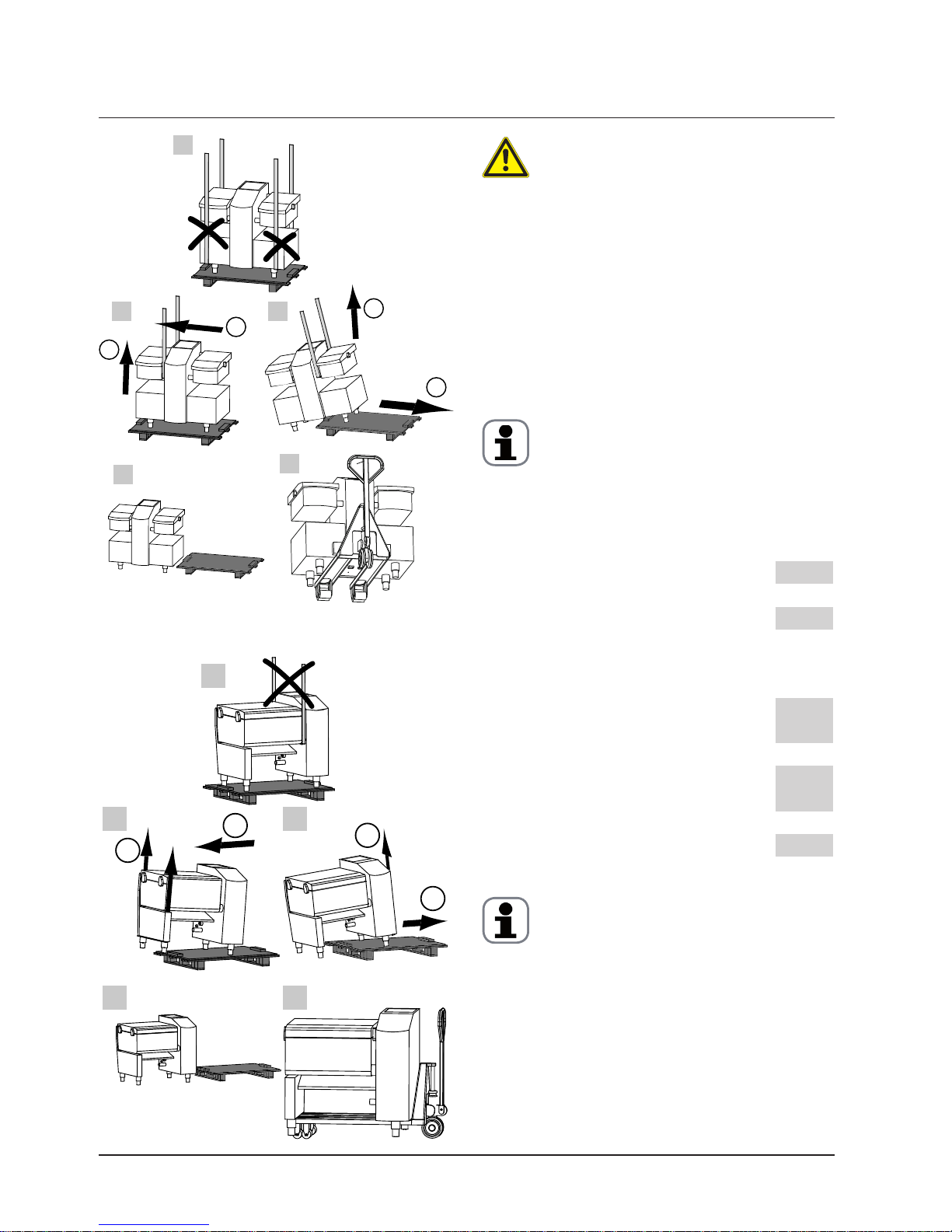
Take care!
Observe the weight of the units. Use carrying
aid to avoid injuries. Wear appropriate ppe's
Type 112:
(Vitro + cabinet)
168 kg
Type 112+:
(Vitro + cabinet)
186 kg
Type 211:
(Vitro)
195 kg
Type 211+:
(Vitro)
223 kg
Type 311:
(Vitro)
251 kg
Type 311+:
(Vitro)
279 kg
Attention:
In order to avoid damages observe procedure shown
on pictures A to E.
For 112 models it is forbidden to lift the unit at the
bottom of the cabinet. Pict. A
For 211 and 311 models it is forbidden to lift the
unit at the axle of the pan or of the lid. Pict. A
Procedure:
• Lift up unit at one side using carrying aids as
shown on Pict. B
• Pull the unit off to the side Pict. C
• Lift up unit at the side which is still standing on
the pallet and pull out pallet. Pict. C
• Lower the unit. Pict. D
• For transporting the units without pallets use the
pallet jack as shown on Pict. E
Attention:
To move 211 - 311 models without palette the following must be observed. Use two wood bars with
a minimum length of the unit and put them on the
pallett jack.
Run pallet jack in lengthways underneath the unit.
Thus the weight of the unit is evenly allocated to
the cross bars.
Observe center of gravity - danger of tilting!
Handling: Take the unit off the pallet
- 6 -
v08
112
211/311
A
1
2
2
1
B
E
D
C
A
B
E
D
C
1
2
1
2
Page 7
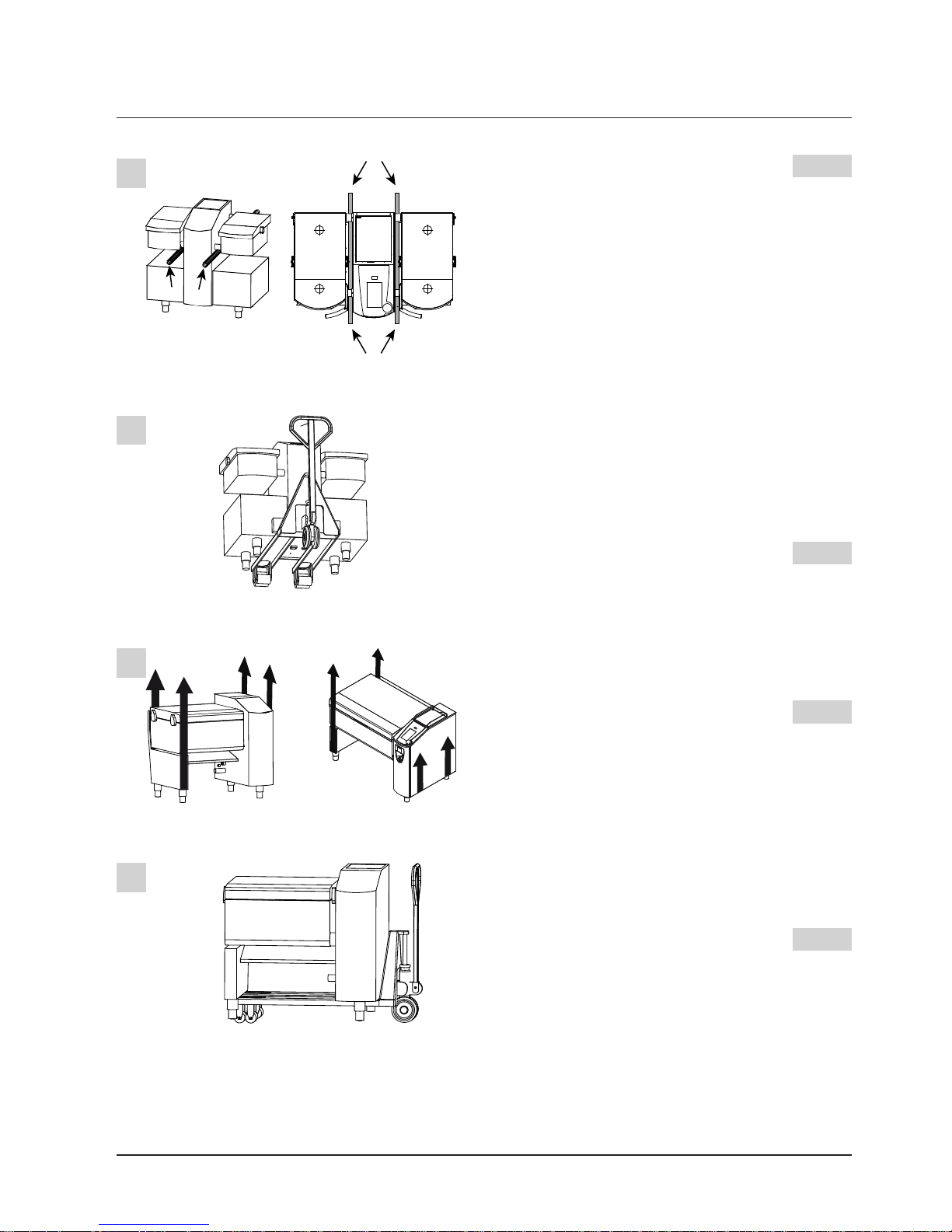
Models 112, handling by hand
Pict. 1
We recommend you to handle the unit from the axis
of the pan and from the rear gully under the lid axis.
Models 112, handling with pallet jack.
To carry the unit with a pallet jack, take care to lift
the unit from the front or from the rear, not from
the sides.
Pict. 2
Models 211 & 311, handling by hand
Handle unit from left and right frame. Pict. 3
Models 211 & 311, handling with pallet jack
To carry the unit with a pallet jack, take care to lift it
either from the left or from the right side. Pict. 4
If however you wish to lift such units from the frame
central crosspiece it is mandatory to use beams of
wood to distribute the load of weight.
Handling: Unit without pallet
- 7 -
v08
1
2
3
4
Page 8
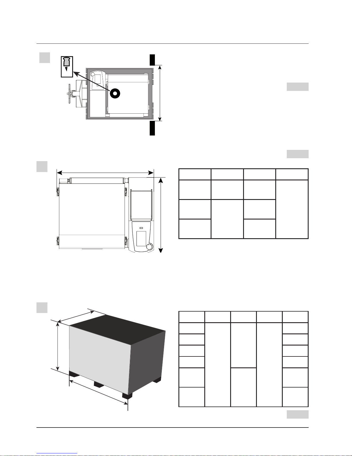
We highly recommend you to transport the
unit as far as you can on a pallet jack.
Center of gravity Pict. 1
Required passage width with pallet:
Models 112 / 211 / 311 1010 mm / 40"
Devices maximum size: Pict. 2
X (mm) Y (mm) H* (mm)
112+ 780
30 3/4"
1220
48 1/8"
1100
43 3/8"
211+
920
36 1/4"
1164
45 7/8"
311+ 1542
60 3/4"
* H = Height with standard foots
Height of the standard foot = 150 mm (6")
Dimensions and weight of units with packaging
X (mm) Y (mm) Z (mm) P (kg)
112
1325
52 1/4"
1300
51 1/4"
1000
39 1/2"
202
112+ 212
211 230
211+ 257
311
1700
67"
299
311+
335
Pict. 3
Handling: Size for carrying
- 8 -
v08
1
2
3
X
Y
X
G
X
Y
Z
Page 9
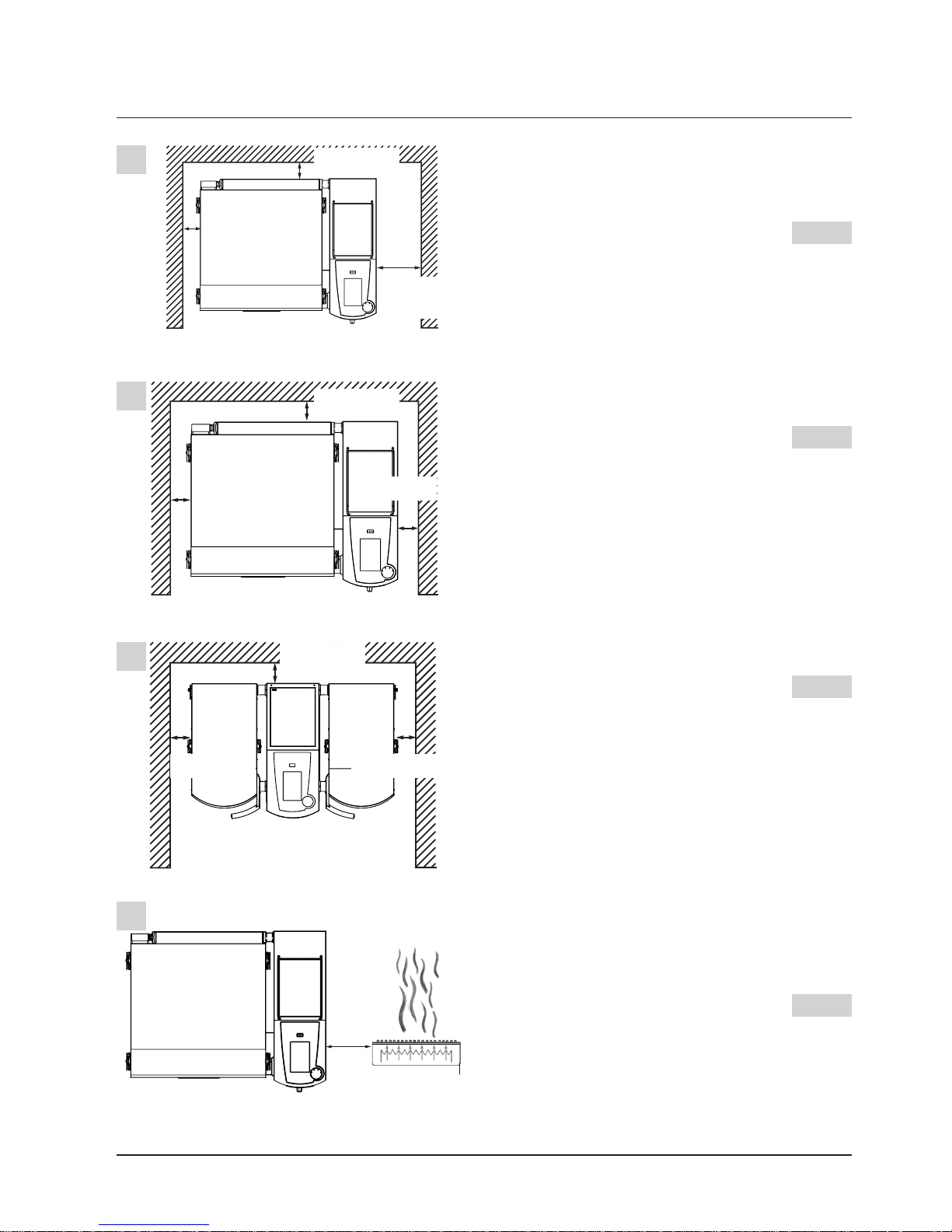
Engineer access
We recommend a distance of 500 mm (20”) on the
right hand side of the unit for carrying out maintenance work. Fig. 1
Minimum clearance for 211 & 311 models
Right, left & back space 50 mm as shown Fig. 2
Minimum clearance for 112 models
Right, left & back space 50 mm as shown Fig. 3
Protection against heat radiation
Minimum space on the right side is 350 mm,
(13 3/4"), as shown on Pict. 4
Installation: Recommended minimum clearance
- 9 -
v08
1
2
4
3
50 mm / 2"
50 mm / 2"
50 mm / 2"
50 mm / 2" 50 mm / 2"
50 mm / 2"
350 mm
14"
50 mm / 2"
500 mm
20"
50 mm / 2"
Page 10
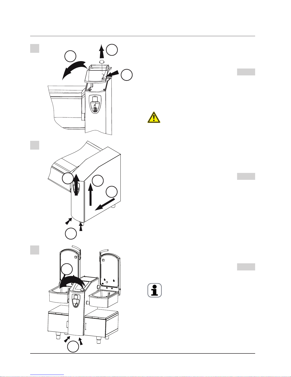
Acessing the unit:
Step 1
This step is valid for all kind of units Pict.1
(1) Pull off central dial
(2) Loosen screw (3 mm hex socket)
(3) Now you can remove the control panel.
The control panel is connected with a cable
mass. to the electric board. Take care not to damage it.
Step 2
(211 & 311 models)
To access the whole electric board you must now
remove the front panel and the side panel. To do so:
Pict. 2
(1) Loosen both screws under the front panel (3 mm
hex socket)
(2) Lift front panel without removing it completely!
(3) Slide side panel to the front
(4) Remove side panel by lifting it
Step 2
(112 models)
(1) Once the control panel removed and standing
either on the left pan or left lid
(2) Loosen both screws under the front panel (3mm
hex socket) Pict. 3
Attention
When reassembling the control panel, make sure
to apply enough pressure on the left side corner in
order to ensure the latch engages. Thus facilitating
a sufficient sealing of the technical compartment.
Installation: Opening the unit
- 10 -
v08
1
2
3
1
2
3
1
2
4
3
2
1
Page 11

We built our units by level. That means
the pan is in accordance with the frame. Once you
have levelled the frame, the pan should be levelled
also.
The levelling is done exclusively by adjusting the
foots of the unit. Proceed as follows:
Step 1
Units are delivered with the foots fully screwed.
Before starting to level the unit unscrew each foot
of two turns. Pict. 1
Step 2
Open side panel and level unity by adjusting both
foots. Pict. 2
Step 3
3. Open the lid and check pan level from the right to
the left. Adjust if necessary by turning the left front
foot. Pict. 3
Step 4
Check pan level from the front to the rear.
Adjust the left back foot if necessary. Pict. 4
Levelling: 211 or 311 units
- 11 -
v08
1
2
3
4
x2
x2
x2
x2
Page 12

Step 5
Check the pan is laying on both stop collars, thus
are factory adjusted.
If it is necessary to adjust the stops of the pan take
care of following: Pict. 5
> The base frame must be fully levelled. It is useless
adjusting the pans stops as long as the base frame
isn't properly levelled.
> That the lid doesn't collide with the pan when
closing.
Step 6
Move the lid full downward and check for lid to pan
lining up. If necessary adjust using the left rear foot.
Pict. 6
For 211 & 311 pressure models, ensure that when
the lid is lying on the pan there is not too much
play in between. This could lead to damage the unit
while locking the lid for a pressure cooking mode.
Step 7
Characteristic of the models 211 et 311 with
pressure option
Ensure the distance between the four locking hooks
and the edge of the pan is even.
This is a very important check! Pict. 7
We highly recommend to fix pressure units on the
floor using our special fixing accessory. (Refer to
"option floor fixing" in the chapter options.
Levelling: 211 or 311 units
- 12 -
v08
7
5
6
Page 13

We built our units by level. That means the
pan is in accordance with the frame. Once you have
levelled the frame, the pan should be levelled also.
The levelling is done exclusively by adjusting the
foots of the unit. Proceed as follows:
Step 1
Units are delivered with the foots fully screwed.
Before starting to level the unit unscrew each foot
of two turns. Pict. 1
Step 2
Put your level on the right or left pan as you like.
Start levelling the unit from the left to the right. To
do so adjust the front legs of the device.
Pict. 2
Check now the setting on the opposite pan.
Step 3
Put your level on the right or left pan as you like.
Now you can level the unit from the front to the rear.
To do so adjust the rear feet of the unit.
Pict. 3
Check on the opposite pan.
Levelling: 112 units
- 13 -
v08
1
x2
x2
x2
x
2
2
3
Page 14

Requirement
You need to ensure, depending on the
national and local regulations, that each of our
devices are separately connected through a
30mA RCD circuit breaker. This device must
be located in the electrical distribution box.
Regulation
• Follow the installation instructions
and the information on the nameplate when connecting the unit
(See plate description on next page).
• Equipment must be connected to an electrical
supply line with standards in your country.
• Observe your local electricity supplier regulations.
• On-site installation: provide accessible all-pole
disconnection device with a minimum of a 3
mm contact gap.
• Applicable standards: EN 60335, IEC 60335
Power supply cable:
• Electrical connection data see page 17
• For appliance connections, precise dimensions
and connection points, see pages 15 - 18 or
data sheets page 28 - 30.
• Units can be connected directly or through a
suitable connector.
• Before connecting or disconnecting the mains
be sure the unit is switched off.
• Use at least a cable quality like HO7RN-F
if flexible, V1000R02V if rigid. Take
care to tighten enough the cable gland.
(Stress relief)
• The cross-section of the power cables must be
based on the current consumption and on local
regulations.
Electric wiring diagrams
• The wiring diagram can be found inside
a plastic bag in the technical compartment, after removing the side panel. See
chapter: installation, accessing the units.
Please put it again there after using it.
Power supply: Common information
- 14 -
v08
Page 15

Name plate: Description
Models description:
• 112, 211, 311
• 112+, 211+, 311+
("+" Stands for pressure models)
Power supply
Power consumption
Water pressure
Serial number of the VarioCooking Center
©.
For any technical support it is mandatory to
remind this number.
Name of the person who built this unit.
Every single VarioCooking Center© is built
by a single person.
Certificates and approvals
Power supply: Type of the unit
- 15 -
v08
3NAC - 400V
Page 16

Danger !
When connecting the unit check the power
supply voltage matches the one the unit was
built for. See the unit plate.
Observe colour coding of the wires. Wrong
connection can cause electric shock or damage of
the unit. (e.g. PCB boards)
Common information see page 14
Connecting 112 models: Pict. 1
The main terminals are located inside the electrical
compartment and are accessible after removing the
front panel (2).
(1) Cable gland for power cord
(2) Front panel
(3) Earth bonding
Connecting 211 or 311 models: Pict. 2
The main terminals are located inside the electrical
compartment and are accessible after removing the
side panel.
Connect the supply as follows:
Yellow/green terminals : Earthing
Blue terminals: Neutral (Only when 3NAC)
Grey terminals : L1,L2,L3, (non-phase-sequencedependent)
The screw for the earth bonding (3) is located on
the bottom side of the unit. Connect the wire of the
earth bonding to this place.
Power supply
- 16 -
v08
1
2
1
3
2
1
3
Page 17

Connected loads
3 NAC 400 V
112 112 with
vitro
211 211 with
vitro
311 311 with
vitro
Power (kW)* 17 19 28 31 45 47
Current consumption (A) 23 34 47 47 70 70
Fuse (A) 25 40 50 50 80 80
Cross section
recommended (mm²)
2,5 6 10 10 16 16
3 NAC 400 V Dynamic
112 112 with
vitro
211 211 with
vitro
311 311 with
vitro
Power (kW)* 13 15 22 24 35 37
Current consumption (A) 19 29 37 37 56 57
Fuse (A) 20 32 40 40 63 63
Cross section
recommended (mm²)
2,5 4 6 6 10 10
3 NAC 415 V
112 112 with
vitro
211 211 with
vitro
311 311 with
vitro
Power (kW)* 18 20 30 32 47 50
Current consumption (A) 25 35 49 49 74 74
Fuse (A) 25 40 50 50 80 80
Cross section
recommended (mm²)
2,5 6 10 10 16 16
3 NAC 415 V Dynamic
112 112 with
vitro
211 211 with
vitro
311 311 with
vitro
Power (kW)* 14 17 23 26 37 40
Current consumption (A) 19 30 39 39 58 59
Fuse (A) 20 32 40 40 63 63
Cross section
recommended (mm²)
2,5 4 6 6 10 10
Caution:
As written on page 14, the unit has to be connected through a 30 mA circuit breaker.
- 17 -
v08
Page 18

For other voltages please contact the manufacturer
* Doesn't include power consumption from the embedded socket.
** Not available!
3 AC 400 V
112 112 with
vitro
211 211 with
vitro
311 311 with
vitro
Power (kW)* 13 ** 26 ** 42 **
Current consumption (A) 19 ** 41 ** 61 **
Fuse (A) 20 ** 50 ** 63 **
Cross section
recommended (mm²)
2,5 ** 10 ** 10 **
3 AC 440 V
112 112 with
vitro
211 211 with
vitro
311 311 with
vitro
Power (kW)* 16 ** 22 ** 35 **
Current consumption (A) 19 ** 37 ** 56 **
Fuse (A) 20 ** 40 ** 63 **
Cross section
recommended (mm²)
2,5 ** 6 ** 10 **
3 AC 200 V
112 112 with
vitro
211 211 with
vitro
311 311 with
vitro
Power (kW)* 17 19 28 30 45 47
Current consumption (A) 49 58 98 98 146 146
Fuse (A) 50 63 100 100 160 160
Cross section
recommended (mm²)
10 10 25 25 50 50
3 AC 220 V
112 112 with
vitro
211 211 with
vitro
311 311 with
vitro
Power (kW)* 15 17 25 26 40 42
Current consumption (A) 39 49 78 78 117 117
Fuse (A) 40 50 80 80 125 125
Cross section
recommended (mm²)
6 10 16 16 35 35
Connected loads
- 18 -
v08
Page 19

Concerning the cross section of the cables
Current consumption, recommended fuses and
cross-sections are depending also on:
• Local prescriptions
• Cable length & quality
• Quality of the power supply network.
Thus they are to be adapted to local conditions.
Values shown are for a maximum cable length of 2
m. It is the responsibility of the person installing the
unit to adjust these values according to the length
of cable which will be in use.
Concerning the supply voltage
The maximum allowable tolerance of the supply voltage (supply voltage see name plate) is in the range
of -10% up to +10%.
Maximum dimensions of power supply cables
Maximum cable diameter (Cable gland)
Models 112 Ø Max. 25 mm
Models 211/311 Ø Max. 32 mm
Maximum cross section (For cable connection)
Units 3NAC400V, 3NAC415V, 3AC400V, 3AC440V
All models Max. 25 mm
2
Units 3AC220V
Models 112 Max. 25 mm
2
Models 211/311 Max. 35 mm
2
Power consuption in special mode
Show-mode* Reduced 230 W
Show mode* On 115 W
Socket: Protection fuse, power available
Model 112
Country Fuse Available power
All 10 A 2.3 kW
Model 211 / 311
Country Fuse Available power
D, F 16 A 3.6 kW
CH, I 10 A 2.3 kW
GB , DK 13 A 2.9 kW
Other countries on request.
* Show-Mode, refer to the user manual!
Connection load
- 19 -
v08
Page 20

Common information
Our units comply with NF EN 1717: 2001-05 regulations, which are recognised by the SVGW and DVGW.
A soft water connection is not necessary. If regardless the unit shall be connected to soft water make
sure that the remaining water hardness is set to 5°e
(7°fH or 4°dH) minimum
The appliance must be connected to the facility
water supply with a supply hose that conforms to
EN 61770 resp. IEC 61770 or of similar quality.
The water supply hose must fulfil the local or standard hygiene requirements for hoses in drinking water
systems.
We recommend to install an individual shut-off valve
for each appliance
We do not talk here about local specific laws.
Installers are responsible to take account of local
regulations.
Connection
(1) Cold water supply (3/4“)
Quenching or Pan filling
(2) Hot water supply* (3/4“)
Pan filling only. Max 60°C
Models 112 Pict. 1
Models 211/311 Pict. 2
Pressure & flow
Water pressure has to be in the range between
150 kPa and 600 kPa. Recommended is 300 kPa
minimum.
Nominal flow should be between: 1,8 to 2,5 m3/h
Temperature
For units without hot water connection, maximum
temperature of cold water connection should not
exceed (30°C- 86°F) max.
For units fitted with hot water connection, the temperature should not exeed 60°C or 140°F. Take care
of the connection!
*Hot water connection is an option, devices are not
fitted as standard.
Water connection
- 20 -
v08
1
2
30°C/86°F
150-300kPa
21-87 psi
3/4"
1 2
1
2
30°C/86°F
150-300kPa
21-87 psi
3/4"
Page 21

Feature of the VarioCooking Center
®
Fixed connection with odour lock is permissible;
thanks to a ventilated drain line which is integrated
in our units
A connection set for the drain is available (Water
supply and drain).
Set ref. (Unit without hot water option) 87.00.174
Set ref. (Unit whit hot water option) 87.00.545
Attention!
• Discharging of the pan can be done with hot
water.
• Drain pipe must be capable of withstanding
steam,temperature - don't use hoses.
• Drain water temperature < 100°C
Requirements
• Welding of drain pipe to the units drain is not permissible.
• Drain pipe must be equipped with a odour lock.
• The unit drain is ventilated. This consist of a square
pipe coming out of the unit. It is forbidden to obstruct
it, to cover it or to change his square shape.
• Drain pipe must have the same diameter as the output pipe of the unit, no reduction in diameter should
be inserted.
• The drain pipe must have a constant slope of at least
3%
Models 112
The drain pipe with ID 40 mm is located on the
bottom side of the center support Pict. 3
The maximum height of the wall inlet is 380 mm
(15"). (Midle of the pipe) Pict. 1
Models 211/311
The drain pipe with ID 50 mm is located on the
inner side of the right unit support. Pict. 4
The maximum height of the wall inlet is 200 mm
(7 3/4"). (Middle of the pipe) Pict. 2
(1) Drain ventilation
(2) Drain connection
Drain connection
- 21 -
v08
200 mm Max
(7
3/4
")
150 - 170 Max
5
3/4
"
- 6
11/16
"
Ø50 mm
(2")
50 mm Min
(2")
2
2
1
1
1
2
3
4
380 mm Max
(15")
150 - 170 Max
5
3/4
"
- 6
11/16
"
Ø40 mm
(1
1/2
")
Page 22

Observation:
Pict. 1
A gutter installation is not necessary for our units.
If despite that your client wants this, please observe
the following:
Requirements
• Drain pipe must have the same diameter as
the output pipe of the unit, no reduction in
diameter should be inserted.
• The drain pipe must have a constant slope of at
least 3%
• A clear outflow of 2 cm (1”) must be provided
between the drain pipe and the gully grille.
Although we recommend 50 mm (2") distance
in order to make cleaning easier.
Advice
In case of evacuation down to a gully you should
avoid as much as possible to drive the pipe output
underneath the unit main compartment.
Water discharge: Discharge to a gutter
- 22 -
v08
Min 20 mm
3/4"
Min 3 %
1
Page 23

Adjusting the installation heigh
Pict. 1
If the altitude of installation is higher than the unit
default value (0-299m) it is necessary to modify and
validate.
• Modify the altitude (300 m steps)
• Do not forget to validate
Calibration
The VarioCooking Center® are factory calibrated.
There is no need to calibrate it again after installation altitude adjustment.
Stainless steel cleaning cloth
We attach great importance to the quality of the
installation. Also we deliver in the starter kit a set
of cleaning wipes soaked with highly refined mineral
oil. Do not use it inside the pan.
Pict. 2
First startup
VCC
Installation Altitude
Please check and configure
Installation altitude
- 23 -
v08
1
2
0 m - 299m
OK
Page 24

Floor fixing plate
It is possible to fix units to the floor using the
optional set"Set for floor fixing" 60.72.905
Pict 1
Attention!
When installing 211 - 311 models with pressure on
the standard foots, we highly recommend to fix the
foots to the floor. This in order to ensure the levelling
of the unit as the alignment between lid and pan
remains unaltered.
Option casters
Attention!
It is forbidden to mount casters on 211+ - 311+
models with pressure option and build before
Mai 2012.
Units ordered with option casters will be delivered
with standard foots. The mounting of the casters
must be done on site. Pay attention that the casters
with brakes are installed at the front of the unit.
Pict. 2
Mounting instructions is supplied with casters.
Casters Kit reference (for all models) 60.71.267
The height of the unit on casters is 150 mm (5 7/8")
Option adjustable stainless steel foots
All models of VarioCooking Center® can be delivered with stainless steel foots. These feet make it
possible to fix the apparatuses on the ground via an
integrated washer.
Pict. 3
h min 105 mm (4 1/8")
h max 170 mm (6 6/8")
Article number (Single) 12.00.850
Installation Options
- 24 -
v08
1
2
3
h
Page 25

Set for base frame
Units ordered with option base frame will be delivered with standard legs. The mounting of the base
frame must be done on site.
112 Pict. 1
211/311 Pict. 2
Mounting instructions is supplied with the base
frame. For levelling of the unit refer to the chapter
levelling.
Article number
Models 112 12.00.706
Models 211/311 12.00.704
Base frame mounting dimensions
Models High under
unit
Max. high of base
frame (recommended.)
112 50 mm
+/- 5mm
120 mm
211/311 65 mm
+/- 5mm
105 mm
Set for wall mounting
Assembling of these set must be done on site.
Pict. 3
Mounting instructions is supplied with the wall
mounting set. For levelling of the unit refer to the
chapter levelling.
Wall mounting set article number
Models 211/311 only 12.00.751
Heightening kit 100 mm for foots/Casters
The mounting between the frame and the foot or
casters has to be done on site. Pict. 4
Article number of the kit 100 mm
All models 60.72.341
(Made of 4 pieces)
Installation Options
- 25 -
v08
1
3
2
4
Page 26

Option rear drain
(Only for 112 and 112+ models)
Models 112 only can be delivered with the drain
outlet at the rear side of the unit, in case the
standard output position of the drain is too low. This
option is not factory assembled.
Pict. 1
This option can also be retrofitted. The article number of the set is 60.71.915
Dimensions Pict. 2
A 85 mm
3 3/8"
B 250 mm
9 7/8"
C 150-170 mm
6"- 6 3/4"
(According to adjustment)
Ethernet
The Ethernet option is different for models 112 and
211/311.
On 112 models you must connect your Ethernet
cable directly on the main board. Take care to lay the
cable with the existing strand. Do not pass trough
mechanical components. They could damage the
cable during their movement.
Pict. 3
On 211/311 models a socket is provided near the
main contactor. You can directly plug your Ethernet
cable with an RJ45 connector.
Pict. 4
Installation Options
- 26 -
v08
A
B
C
2
1
3
4
Page 27

Energy optimization System, Sicotronic
If equipped with this option the unit is pre-wired for
connection to an energy optimization system (Typ
Sicotronic).
Connect your Energy optimization system following
the wiring diagram supplied with the VarioCooking
Center®.
Connection locations:
Models 112 Pict.1
Models 211/311 Pict. 2
Installation Options
- 27 -
v08
2
1
Page 28

Conversion table
- 28 -
v08
°dH °f °e ppm mmol/l gr/gal(US) mval/kg
1 °dH 1 1,79 1,25 17,9 0,1783 1,044 0,357
1 °f 0,56 1 0,70 10,0 0,1 0,584 0,2
1 °e 0,8 1,43 1 14,32 0,14 0,84 0,286
1 ppm 0,056 0,1 0,07 1 0,01 0,0584 0,02
1 mmol/l 5,6 0,001 0,0007 100 1 0,00058 2
1 gr/gal (US) 0,96 1,71 1,20 17,1 0,171 1 0,342
1 mval/kg 2,8 5,0 3,5 50 0,5 2,922 1
1 °dH: 10,00 mg CaO/kg 1 ppm : 0,56 mg CaO/kg 1 gr/gal : 9,60 mg CaO/kg
(Germany) 17,86 mg CaCO3/kg (USA) 1,0 mg CaCO3/kg (USA) 64,8 mg CaCO3/gal
7,14 mg Ca
2
+
/kg 0,40 mg Ca
2
+
/kg 17,11 mg CaCO3/kg
1 °f : 5,60 mg CaO/kg 1 mmol/l : 56,00 mg CaO/kg 6,85 mg Ca
2
+
/kg
(France) 10,0 mg CaCO3/kg (chem. conz.) 100,0 mg CaCO3/kg
4,00 mg Ca
2
+
/kg 39,98 mg Ca
2
+
/kg
1 °e : 8,01 mg CaO/kg 1 mval/kg : 28,00 mg CaO/kg
(GB) 14,3 mg CaCO3/kg (Milliäquivalent) 50,0 mg CaCO3/kg
5,72 mg Ca
2
+
/kg 19,99 mg Ca
2
+
/kg
kPa mbar psi inch/wc
0,1 1 0,0147 0,4014
0,2 2 0,0294 0,8028
0,3 3 0,0441 1,2042
0,4 4 0,0588 1,6056
0,5 5 0,0735 2,0070
0,6 6 0,0882 2,4084
0,7 7 0,1029 2,8098
0,8 8 0,1176 3,2112
0,9 9 0,1323 3,6126
1 10 0,147 4,0140
1,2 12 0,1764 4,8168
1,4 14 0,2058 5,6196
1,6 16 0,2352 6,4224
1,8 18 0,2646 7,2252
2 20 0,294 8,0280
2,5 25 0,3675 10,0350
3 30 0,441 12,0420
3,5 35 0,5145 14,0490
kPa mbar psi inch/wc
4 40 0,588 16,0560
4,5 45 0,6615 18,0630
5 50 0,735 20,0700
5,5 55 0,8085 22,0770
6 60 0,882 24,0840
6,5 65 0,9555 26,0910
7 70 1,029 28,0980
7,5 75 1,1025 30,1050
8 80 1,176 32,1120
8,5 85 1,2495 34,1190
9 90 1,323 36,1260
9,5 95 1,3965 38,1330
10 100 1,47 40,1400
20 200 2,94 80,2800
30 300 4,41 120,4200
40 400 5,88 160,5600
50 500 7,35 200,7000
100 1000 14,7 401,4000
Page 29

Unit dimensions
VarioCooking Center® 112
(1) Drain connections DN40
(2) Water supply warm G3/4 - (Option)
(3) Water supply cold G3/4
(4) Energie optimizer - Sicotronic - (Option)
(5) Ethernet - (Option)
(6) Electrical power supply
(7) Overflow
(8) Equipotentyial bonding M6x10
(9) Overflow hosereel
Minimum space
- 29 -
v08
628 (24 3/4)
(25 3/4)655
589 (23 1/4)
610 (24)
319 (12 1/2)
800 (31 1/2)
(17)
687 (27)
524 (20 5/8)
434
132
210 (8 1/4)
47 (1 7/8)
343 (13 1/2)
1220
469 (18 1/2)
409 (16)
(5 1/4)
(48)
50 (2)
min.50 (2)
min.50 (2)
444 (17 1/2)
494 (19 1/2)
563 (22 1/8)
611 (24 1/8)
9
5
6
4
3
2
1
7
8
979
516
1100
1147 (45 1/8)
(38 1/2)
(20 1/4)
(43 3/8)
(5 7/8)148
304 (12)
1168 (46) -VarioCooking Center 112
1224 (48 1/5) -VarioCooking Center 112+
(30 1/2)
(28 7/8)
777
1667
684
733
(27)
(65 5/8)
max. 80°
max. 75°
91 (3 3/5)
12 (0.5)
160 (6.3)
Page 30

Unit dimensions
VarioCooking Center® 211
(1) Drain connections DN40
(2) Water supply warm G3/4 - (Option)
(3) Water supply cold G3/4
(4) Energie optimizer - Sicotronic - (Option)
(5) Ethernet - (Option)
(6) Electrical power supply
(7) Overflow
(8) Equipotentyial bonding M6x10
(9) Overflow hosereel
Minimum space
- 30 -
v08
1002
19 (3/4)
71 (2 3/4)
(2 1/8)
(25) (6)
958 (37 3/4)
(12)
54
635 152
304
129 (5 1/8)
789 (31 1/8)
1140 (45)
(39 1/2)
734 (28 7/8)
50 (2)
min.50 (2)min.50 (2)
739 (29 1/8)
89 (3 1/2)
950 (37 2/5)150 (6)
8
9
1164 (45 7/8) -VarioCooking Center 211+
1140 (45) -VarioCooking Center 211
914 (36)
264 (10 3/8)
351 (13 3/4)
305 (12)
604 (23 3/4)
939 (37)
1742 (68 1/2)
454 (17 7/8)
165 (6 1/2)
172 (6 6/8)
193 (7 5/8)
256 (10 1/8)
336 (13 2/8)
255 (10)
386 (15 1/4)
max. 80°
max. 85°
153 (6)
180 (7 1/10)
6
5
1
2
3
4
7
Page 31

Unit dimensions
VarioCooking Center® 311
(1) Drain connections DN40
(2) Water supply warm G3/4 - (Option)
(3) Water supply cold G3/4
(4) Energie optimizer - Sicotronic - (Option)
(5) Ethernet - (Option)
(6) Electrical power supply
(7) Overflow
(8) Equipotentyial bonding M6x10
(9) Overflow hosereel
Minimum space
- 31 -
v08
(3 1/2)
1002 (39 1/2)
19 (3/4)
71 (2 3/4)
(2 1/8)
1336 (52 5/8)
(12)
(43 3/8)
(6)
739 (29 1/8)
54
635 (25) 152 (6)
1100
304
150
129 (5 1/8)
1167 (46)
89
min.50 (2)min.50 (2)
50 (2)
734 (28 7/8)
8
9
1518 (59 3/4) -VarioCooking Center 311
1542 (60 3/4) -VarioCooking Center 311+
914 (36)
264 (10 3/8)
351 (13 3/4)
305 (12)
604 (23 3/4)
939 (37)
1742 (68 1/2)
454 (17 7/8)
165 (6 1/2)
172 (6 6/8)
193 (7 5/8)
256 (10 1/8)
336 (13 2/8)
255 (10)
386 (15 1/4)
max. 80°
max. 85°
153 (6)
180 (7 1/10)
6
5
1
2
3
4
7
Page 32

English
We reserve the rights to make any technical improvments!
We assume no liability for typing errors.
80.05.145
If you notice a mistake in this manual do not hesitate to advise us!
Photocopy this page, enter your remarks in reference to the exact page and send it by
fax. Our contact information in the documents supplied with the apparatus.
Remarks:
Page
Document validity:
Model of VarioCooking Center
®
112
211
311
Serial number
E11xH1110xxxxxxx
E21xH1110xxxxxxx
E31xH1110xxxxxxx
Manufacturing year
2011 / 10
2011 / 10
2011 / 10
· VarioCookingCenter® V-08 · Keni · 07/2018
 Loading...